1
Gas Flow Bench
User Manual
Mesa’s Commitment
As a manufacturer of critical equipment, quality is the highest priority in
our manufacturing process. Mesa commits to providing creative,
innovative thinking and the engineering and scientific expertise needed to
produce gas flow-related products and solutions that are universally
recognized for their superior performance, quality and value.
Proven Bios DryCal® technology is the recognized leader in gas flow
measurement, providing the industry’s most reliable products, service and
solutions for professionals in environmental protection, workplace safety,
industrial process control and laboratory calibration.
We strive to provide the closest NIST-traceable, legal defensibility of any
flow calibration equipment manufacturer, and we actively maintain our
NVLAP (NIST) ISO 17025 laboratory accreditation in order to support our
claims and continually improve our quality system and laboratory proficiency. Thank you for purchasing our products. From all of us at Mesa,
best wishes for many years of accurate, defensible primary flow
measurements.
Mesa Laboratories Inc. 10 Park Place Butler, NJ 07405 USA
(973) 492-8400 FAX (303) 484-4992 www.mesalabs.com Symbol "MLAB” on the NASDAQ
2
Table of Contents
Register Your Product........................................................................................................2
About Flow Bench.............................................................................................................2
Configurations...................................................................................................................2
Leak Test Procedure..........................................................................................................5
Application........................................................................................................................7
Recalibration...................................................................................................................16
Accuracy
Reliability
Convenience
1
Register Your Product
Before we begin, please register your product with Mesa Laboratories, Inc. To complete your registration,
log on to our website at www.drycal.com and complete the registration form. Registration of your new
Bios DryCal product ensures your instruments warranty claim information is properly documented in Mesa’s
database, and provides you the peace of mind that your new calibration equipment is covered under our
warranty service plan.
About Flow Bench
Gas flow benches offer practical engineered solutions for calibration of gas flow measurement devices using Proven Bios DryCal® technology. Mesa flow benches are configured to provide the stable flow critical to
the calibration process. Our configurations use different components to connect the gas source, regulate
pressure, control the flow, and direct the flow to a specific device being calibrated against a DryCal® standard.
Configurations
The Mesa Flow Benches are pre-configured for specific applications.
They are available in different configurations.
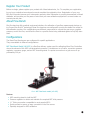
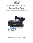
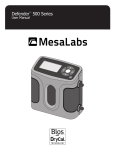
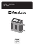
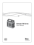
MFC Flow Bench Model (100-025) is a Gas flow delivery system used for calibrating Mass Flow Controllers
where the exhaust of the MFC is at atmospheric pressure. It includes an on-off valve, a precision pressure
regulator, a pressure gauge, and an MFC mounting stand. It requires connection to a gas source of approximately 100 psi.
Pic 1: MFC Flow Bench model (100-025)
Features
•
•
•
•
•
M
FC mounting stand to hold the MFC
P
ressure regulator to obtain and maintain the required MFC inlet pressure
¼
” Tubing connection compatible to most popular MFCs
Q
uick-connect to secure an easy connection to the flow source
S
pecially designed for MFC calibration
2
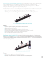
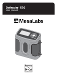
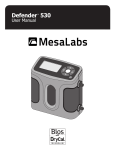
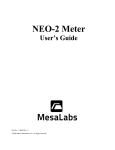
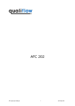
General Purpose Flow Bench Model (100-030 L/H) is a gas flow delivery system used for calibrating rotameters, bubble meters, and flow calibrators. It includes an on-off valve, a precision pressure
regulator, a high side pressure gauge, a needle valve, a low side pressure gauge and an A/B valve.
It requires connection to a gas source of approximately 100 psi.
The General Purpose Flow bench can be configured as low and high flow based on needle valve selected, either:
• M
esa part number 100-007, Low Flow Needle Valve for a flow rate 5-5000 cc/min
• O
r Mesa part number 100-008, High Flow Needle Valve for a flow rate 500-50,000 cc/min
Pic 2: General Purpose Flow Bench Model (100-030 L/H)
Features
•
•
•
•
•
•
P
ressure regulator to obtain and maintain the desired pressure
N
eedle valve to control the flow
Q
uick-connect to secure an easy connection to the flow source
L ow side pressure gauge to measure the pressure drop across the flow meter
C
onfigured to calibrate any kind of flow measurement device
C
an be configured to calibrate mass flow meters
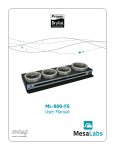
Back Pressure Module Model (100-028) is an add-on Module that allows calibration of a device under
test (DUT) at back pressure of up to 60 PSI. It includes a Pressure gauge and a Back Pressure Regulator.
The back pressure module is used in conjunction with flow bench 100-025 or 100-030 for calibrating flow
meters at a specific pressure.
Pic 3: Back pressure module with 100-025
Features
• B
ack pressure regulator to create a specific pressure
• S
pecially designed for MFC and rotameter calibration at a specific pressure
3
The Mesa General Purpose Flow Bench, 5 to 500 SLM (100-031): is pre-configured for most calibration
applications. This includes Variable Area Flow Meters, Piston Provers, Bubble Meters, Mass Flow
Controllers, and Mass Flow Meters where the exhaust is at atmospheric pressure. If your device being calibrated requires backpressure, contact Mesa for the additional required backpressure module.
General Purpose Flow Bench, 5 to 500 SLM Features
•
•
•
•
•
•
•
P
ressure regulator to obtain and maintain the required inlet pressure
P
ressure gauge to set inlet pressure
V
alves to direct flow to various flow control devices
N
eedle valve to set flow rates from 5 - 50 SLm
0
.063” and 0.125” sonic nozzles to set flow rates from 50 - 500 SLm
A
/B valves to divert flow between the DryCal standard and DUT
1
/2” port to connect a MFC to the pressure regulated gas source
4
Leak Test
MFC Flow Bench Leak Test Procedure
Equipment:
Flow Source
¼” leak test plug
Procedure:
Step 7
Step 1
Open the flow bench regulator to increase pressure
to 80psi or equal to inlet pressure.
Connect flow bench to flow source using 1/4” rigid tubing.
Step 2
Ensure all fittings and components are wrench tight.
Step 3
Ensure inlet valve is closed and open flow source.
Step 4
Turn flow bench regulator counter clockwise to zero flow.
Step 5
Put leak test plug on end of flow bench and tighten.
Step 6
Open the inlet valve to supply gas to flow bench.
Step 8
Close inlet valve and observe the pressure gauge on
flow bench. Any drop in pressure represents a leak.
Retighten fittings if needed and repeat.
Step 9
Ensure no leakage after 5 minutes.
Step 10
Remove leak test plug to release pressure.
Step 11
Disconnect flow bench from flow source.
Step 12
Decrease flow bench regulator.
5
General Purpose Flow Bench (models 100-030L/H) Leak Test Procedure
Equipment:
Flow Source
¼” leak test plug
¼” Swage union
Procedure:
Step 1
Connect flow bench to flow source using 1/4” rigid tubing.
Step 2
Ensure all fittings and components are wrench tight.
Step 3
Ensure inlet valve is closed and open flow source.
Step 4
Turn flow bench regulator counter clockwise to zero flow.
Step 5
Turn needle valve clockwise to zero flow.
Step 6
Open the inlet valve to supply gas to flow bench.
Step 7
Open the flow bench regulator to increase pressure to 80psi
or equal to inlet pressure.
Step 8
Close inlet valve and observe first pressure gauge on flow
bench. Any drop in pressure represents a leak between the
outlet of the inlet valve and the inlet of the needle valve.
Retighten fittings if needed and repeat.
Step 9
Ensure no leakage after 5 minutes and continue.
Step 10
Open needle valve to bleed off pressure.
Step 13
Open inlet valve.
Step 14
Open flow bench regulator to 25psi.
Step 15
Open needle valve and bring low pressure gauge to 25psi.
Step 16
Toggle A/B valve to equalize pressure on either side of
valve.
Step 17
Close needle valve and observe low pressure gauge.
Any pressure drop represents a leak between the outlet
of the needle valve and the ends of the A/B valve tubing.
Retighten fittings if needed and repeat.
Step 18
Ensure no leakage after 5 minutes then turn A/B valve
to other position.
Step 19
Ensure no leakage after 5 minutes.
Step 20
Remove leak test plugs to release pressure and
toggle A/B valve.
Step 21
Disconnect flow bench from flow source.
Step 22
Decrease flow bench regulator and close needle valve.
Step 11
Close flow bench regulator.
Step 12
Put unions and leak test plugs on A/B valve tubing
and tighten.
6
General Purpose Flow Bench, 5 to 500 SLM Leak Test Procedure
Equipment:
Flow Source
¼” leak test plug
¾” leak test cap
Procedure:
Step 13
Step 1
Center ¼” A/B valve selector to open both ports to pressure.
Connect flow bench to flow source.
Step 2
Ensure all fittings and components are wrench tight.
Step 3
Turn flow bench regulator counter clockwise to zero flow.
Step 14
Open the flow bench regulator to increase pressure to
80psi or equal to inlet pressure, then decrease flow bench
regulator completely.
Step 15
Step 5
Observe the pressure gauge. Any pressure drop represents
a leak between the outlet of the needle valve and the ends
of the ¼” A/B valve tubing. Retighten fittings if needed and
repeat.
Turn needle valve clockwise to zero flow.
Step 16
Step 6
Close ¼” valve and open both ½” valves.
pen the flow bench regulator to increase pressure to 80psi
O
or equal to inlet pressure.
Step 17
Step 7
Step 18
Step 4
Close both ½” valves and open ¼” valve.
Decrease flow bench regulator completely.
Step 8
Observe the pressure gauge on flow bench. Any drop in
pressure represents a leak upstream of any closed valve.
Retighten fittings if needed and repeat.
Install leak test caps on ¾” A/B valve and tighten.
Center ¾” A/B valve selector to open both ports to pressure.
Step 19
Step 9
Open the flow bench regulator to increase pressure to
80psi or equal to inlet pressure, then decrease flow bench
regulator completely.
Ensure no leakage after 5 minutes and continue.
Step 20
Step 10
Observe the pressure gauge. Any pressure drop represents
a leak between the outlet of the ½” valve an A/B valve.
Retighten fittings if needed and repeat.
Open needle valve to bleed off pressure.
Step 11
Close flow bench regulator.
Step 12
Step 21
Remove leak test plugs to release pressure. Leak test complete.
Put unions and leak test plugs on A/B valve tubing
and tighten.
7
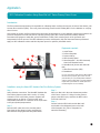
Application
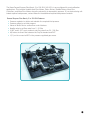
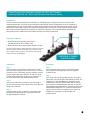
MFC Calibration Procedure Using Mesa Met Lab® Series Primary Piston Prover
Introduction:
The flow measurement professional is responsible for calibrating and/or verifying the accuracy of various flow devices, such
as mass flow controllers (MFCs). This costly, time-consuming process involves sending MFCs out for calibration or verifying
them in-house.
As the leader in primary gas flow measurement, Mesa Labs has developed an on-site calibration solution that combines the
precision and speed of our Met Lab® Series of primary piston provers, MFC control system and carefully-selected
instruments and gauges to enable fast, precise verifications of MFCs, while removing much of the guesswork and
interpretation from the process. This MFC calibration procedure is designed to help the flow measurement professional
apply our MFC calibration solution and Met Lab piston prover for optimum, defensible results.
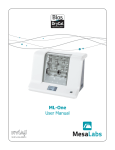
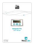
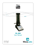
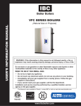
Equipment required:
7
3
1
4
6
2
8
1. On/Off Valve
2. Pressure Regulator
3. Pressure Gauge
4. MFC Mounting Stand
5.Mesa Integrator™ Pro MFC Command,
Control and Readout Device
6. Mesa Met Lab (shown with model ML800)
7. Mass Flow Controller (MFC)
8.Breadboard
For your convenience, Mesa offers the MFC Ambient
Gas Flow Delivery System (part number 100-025,
pictured above) as a pre-packaged MFC calibration
solution; please contact Mesa or an authorized Bios
DryCal sales representative for details (Note: Met
Lab and Integrator 110 not included).
5
Installation using the Mesa MFC Ambient Gas Flow Delivery System:
Step 1
Step 3
Verify all device connections. The Mesa MFC Ambient Gas
Flow Delivery System comes with in-series, ¼” tubing
connection of the on/off valve, pressure regulator and
pressure gauge, as well as a “quick connect” with
male/female connectors for connection of the on/off valve
to the gas cylinder/compressed air.
Place your Met Lab in the most downstream position
of the series. Connect ¼” tubing from the pressure
gauge to the MFC’s input, and from the MFC’s outlet
to the Met Lab’s inlet.
Step 2
Place the MFC under test on the mounting stand.
First check the flow direction before mounting the
MFC and then firmly tighten the base plate screws.
Step 4
Connect both the MFC’s cable and the Met Lab’s
serial cable to the designated ports on the back
of the Integrator Pro (refer to Integrator Pro
manual as necessary).
8
MFC Calibration continued
Procedure:
Application Notes:
Step 1
•A
llow the MFC to warm up before beginning a
calibration by connecting the MFC to the power
supply (or to the Integrator Pro; see Integrator Pro
manual) before inputting a setpoint.
Turn on your Met Lab primary piston prover and
either your Integrator Pro or alternate MFC control box,
as applicable.
Step 2
Set your Met Lab’s measurement type to ‘Std’ (for standardizing) and set its standardizing temperature to match that
of the MFC’s standardizing temperature, typically 0.0C or
21.10C (refer to your Met Lab manual as necessary).
Step 3
If the MFC requires a sensor factor for the gas under test (if
that gas is a surrogate or proxy gas), make sure to change
the Met Lab’s sensor factor to match that of the MFC (the
sensor factor is obtained by the MFC manufacturer).
•A
llow a specified valve change time before recording
the results of consecutive setpoints.
•A
llow the Met Lab to stabilize before beginning a
calibration for optimum measurement results.
•T
he following formula represents the MFC’s
accuracy in comparison to your Met Lab: % Accuracy
(full scale) = (Met Lab measurement - MFC
reading)*100/MFC full scale %
Step 4
Open the on/off valve. Using the pressure regulator, adjust
the gas flow’s pressure to match that of the MFC’s rated
inlet pressure. If the indicated gauge pressure is more
than the MFC’s rated pressure, loosen the connection to
the MFC and simultaneously adjust the pressure regulator
until the desired pressure is achieved.
Step 5
Set the flow to the MFC (as applicable, this is done using
either your Integrator Pro or the alternate MFC control box).
Step 6
Begin taking flow measurements with your Met Lab.
Your Met Lab’s flow measurements are reflected on
your Integrator Pro’s display, along with the deviation
percentage between the MFC and your Met Lab.
9
Variable Area Gas Flow Meter Calibration Procedure Using Mesa Met Lab® Series Primary Piston
Prover
Introduction:
The flow measurement professional is responsible for calibrating and/or verifying the accuracy of various flow measurement
devices, such as variable area gas flow meters (variable area flow meters). This costly, time-consuming process typically
involves sending variable area meters out for calibration or verifying them in-house. As the leader in primary gas flow
measurement, Mesa has developed a simple calibration procedure that combines the precision and high-speed of our
Met Lab® Series of primary piston provers with carefully-selected instruments and gauges to enable accurate calibration
of variable area flow meters.
Flow Corrections:
Each variable area flow meter is designed to operate under a certain set of conditions which include the temperature, pressure and the type of gas. Usually, these conditions are documented directly on the tube enclosure of the variable area flow
meter, with the flow rate scales referenced in mm (millimeter). A reference table is provided to enable you to match the
millimeter readings against the equivalent flow rates at the specified standard temperature and pressure. Otherwise, direct
scale variable area flow meters indicate the flow rates directly on the tube enclosure.
When calibrating variable area flow meters using a Mesa Met Lab primary piston prover, correction must be applied to
the Met Lab’s indicated flow measurements in order to take into account the difference between the actual temperature,
pressure and gas used versus the variable area flow meter’s specified temperature, pressure, and gas requirements.
To properly calibrate variable area flow meters, refer to the following formula:
Variable Area Flow Meter’s Corrected Flow = Variable Area Flow Meter’s Indicated Flow X Correction Factor
Where:
Correction Factor = √ (A x B x C)
Where:
A = The Specific Gravity of the calibration gas as specified by the variable area flow meter / The Specific Gravity of the
calibration gas
B = The operating Pressure in PSIA during calibration / Pressure in PSIA as specified by the variable area flow meter
C = Temperature in ºK as specified by the variable area flow meter / Temperature in ºK during calibration
1
Equipment required:
1. Mesa Gas Flow Delivery System (part number 100-030)
2. M
esa Met Lab Series primary piston prover (models
ML-800, ML-500 or Definer 220)
The Mesa Gas Flow Delivery System features an on/off valve, precision
pressure regulator, high-side and low-side pressure gauges, needle
valve, A-B switch (three-way valve), "quick connect" with male and
female connectors, and breadboard.
2
10
Variable Area Gas Flow Meter Calibration
Installation:
Step 6
Step 1
Set the variable area flow meter’s flow at the desired level
using the needle valve. The flow rate is indicated by the point
on the printed scale where the float’s center stabilizes.
Connect and/or verify all device connections. The Mesa
Gas Flow Delivery System comes with in-series, ¼” tubing
connection of the on/off valve, pressure regulator,
high-range pressure gauges, needle valve and A-B switch,
as well as a “quick connect” with male/female connectors
for connection of the on/off valve to the gas cylinder/
compressed air.
Step 2
Step 7
Wait one to two minutes for the float to stabilize.
To ensure a particular flow point, flip the A-B switch back
and forth a few times to check if the float returns to the
previous scale point. If it needs adjustment, adjust the
flow using the needle valve.
Connect one end of the A-B switch to the inlet fitting of
the variable area flow meter and the other end to the inlet
fitting of your Met Lab.
Step 8
Step 3
Step 9
Using the quick connect, connect the on/off valve to the
gas cylinder/compressed air. Gas inlet pressure should
be approximately 80 to100 psi.
If you are not using a direct scale variable area flow
meter, record the reflected flow rate reading from
the reference flow table against the floating point.
Procedure:
Step 10
Step 1
Close the needle valve, open the on/off valve and set the gas
pressure by adjusting the pressure regulator to above 30 psi.
Step 2
If the variable area flow meter contains a built-in needle
valve, open its needle valve fully for unrestricted gas flow.
Step 3
Turn on your Met Lab primary piston prover. Through its
Setup menu, set your Met Lab’s pressure unit to ‘psi’ and
its flow readings to ‘Vol’ (Volumetric). For other flow
measurement options (such as Continuous readings or
the number of readings in the average), consult your
Met Lab product manual.
Step 4
Record the low range pressure gauge’s pressure
reading (in psia).
Refer to “Flow Corrections” in order to correct the
variable area flow meter’s indicated flow for the
operating temperature, pressure and the type of gas.
Step 11
Flip the A-B switch to your Met Lab. Begin taking flow
measurements with your Met Lab.
Step 12
Determine the full scale accuracy of the variable area flow
meter using the following formula:
% Accuracy = (Met Lab’s Flow Measurement - Variable Area
Flow Meter‘s corrected flow reading)*100 / Variable Area
Flow Meter Full Scale %
Application Notes:
Press your Met Lab’s Read button in order to record
the ambient pressure and temperature.
•W
e recommend taking a minimum of ten flow measurements in an average. The more measurements in the
average, the better the calibration results.
Step 5
• Allow the Met Lab to stabilize before beginning a calibration.
Flip the A-B switch to the variable area flow meter
and gradually begin to open the needle valve on
your flow bench.
•W
hen calibrating a variable area flow meter, it’s best
to use its specified calibration gas (calibrating with a surrogate gas can add greater uncertainty). If a surrogate
must be used, we recommend using one with specific
gravity similar to the gas the variable area flow meter
is designed for.
11
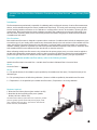
An Alternative Method of Calibrating Variable Area Flow Meter at Rated Temperature
and Pressure Using MetLab Series Primary Piston Prover
Introduction:
The previous Mesa method recommends calibration of a variable area flow meter (rotameter) by applying a correction
factor to the Met Lab’s indicated flow reading for temperature and pressure, without subjecting the rotameter to the
pressure specified for the variable area flow meter. This procedure is recommended as an alternative method for
rotameter calibration where it will be subjected to its rated pressure using the Mesa back pressure module. The back
pressure module consists of a back pressure regulator and a pressure gauge.
Flow Corrections:
Each variable area flow meter is designed to operate under a certain set of conditions which include the temperature,
pressure and the type of gas. Usually, these conditions are documented on the tube enclosure of the rotameter.
A reference table is provided to match the millimeter readings against the equivalent flow rates at the specified
temperature and pressure. Otherwise, direct scale variable area flow meter indicates the flow rates directly
on the tube enclosure.
When calibrating a rotameter using a Mesa Met Lab piston prover, a flow correction factor (FCF) must be applied to the
Met Lab’s indicated flow measurement in order to take into account the difference between the actual temperature versus
the rotameter’s rated temperature.
In this procedure, no correction is applied for the pressure as the equipment set up is designed to calibrate the rotameter
at rated pressure. Correction is applied to the Met Lab’s indicated flow measurement only when the actual gas temperature
differs to its rated temperature.
Flow correction factor, FCF = 1/ √ {(calibration temp in Fahrenheit +460)/(operating temp in Fahrenheit +460)}
Set up diagram:
On/off
valve
Pressure
regulator
Pressure
gauge
Needle
valve
VA
Meter
Back
pressure
gauge
Back
pressure
regulator
Bios
DryCal unit
Equipment required:
1. M
esa Gas Flow Delivery System, consists of on/off valve, pressure regulator, pressure gauge, needle valve
2. B
ack pressure regulator and pressure gauge
3. M
esa Met Lab series Primary Piston Prover (Models ML-800, ML-500, or Definer 220)
Installation:
Step 1
Step 2
Connect all the devices as per the set up diagram.
Connect tubing from the back pressure regulator
to the inlet of the Bios DryCal unit and leave the outlet
open to atmosphere.
The gas flow delivery system comes with a ‘QuickConnect’ with male/female connector that connects the
on/off valve to gas cylinder/compressed air. Connect the
‘Quick-connect’ to the gas flow source. Gas pressure
should be approximately 80 to 100 psi.
12
Procedure:
Step 1
Turn on the Met Lab unit. Through its set up menu, set the
flow reading type to ‘STD’ and Temp Correction Factor to
rated temperature of the rotameter.
Step 2
Through the set up menu, enter the calculated flow
correction factor (FCF) as a Sensor Factor in your Met Lab
unit if the actual gas temperature differs to the rated temperature of rotameter. Otherwise, set its value to default
1.00.
Step 3
Step 6
Set the variable area flow meter’s flow at desired
level using the needle valve. The flow rate is indicated
by the point on the printed scale where the float’s
center stabilizes.
Step 7
If you are not using a direct scale rotameter, record the
reflected flow rate reading from the reference flow table
against the floating point.
Step 8
Press ‘Measure’ or ‘Read’ on the Bios DryCal unit and begin
taking readings.
Close the needle valve, open the on/off valve, and set the
gas pressure by adjusting the pressure regulator to 30 psi
above the rotameter’s rated pressure.
Step 9
Step 4
% Full scale accuracy = (MetLab’s flow reading – VAF’s
indicated flow reading)/ VAF’s full scale %
If the rotameter contains a built-in needle valve,
open its needle valve fully for unrestricted gas flow.
Determine the full scale accuracy of the variable area flow
meter using the following formula:
Step 5
Open up the needle valve and adjust the back pressure
regulator until the pressure gauge before the back pressure
regulator indicates the rotameter’s rated pressure.
13
General Purpose Flow Calibration (models 100-030 L/H) Procedure
Using the Mesa Met Lab® Series and Mesa Gas Flow Delivery System
Introduction:
The flow measurement professional is responsible for calibrating and/or verifying the accuracy of various flow
measurement devices. This costly, time-consuming process typically involves sending devices out for calibration or
verifying devices in-house. As the leader in primary gas flow measurement, Mesa has developed a general purpose
calibration procedure that combines the precision and high-speed of our Met Lab® Series of primary piston provers
with carefully-selected instruments and gauges to enable the calibration of not only Mesa primary standards, but
other piston provers, bubble meters and variable area gas flow meters (rotameters).
Equipment required:
1. M
esa Met Lab Series primary piston prover
(models ML-800, ML-500 or Definer 220)
2. M
esa Gas Flow Delivery System (part number 100-030)
The Mesa Gas Flow Delivery System features an on/off valve, precision
pressure regulator, high-side and low-side pressure gauges, needle
valve, A-B switch (three-way valve), "quick connect" with male and
female connectors, and breadboard.
Calibrating a Variable
Area Flow Meter
Installation:
Procedure:
Step 1
Step 1
Connect and/or verify all device connections. The Mesa
Gas Flow Delivery System comes with in-series, ¼” tubing
connection of the on/off valve, pressure regulator, pressure
gauges, needle valve and A-B switch, as well as a “quick
connect” with male/female connectors for connection of
the on/off valve to the gas cylinder/compressed air.
Close the needle valve, open the on/off valve and set
the gas pressure by adjusting the pressure regulator
to above 30 psi.
Step 2
Connect one end of the A-B switch to the inlet fitting of
the DUT (Device Under Test) and the other end to the inlet
fitting of your Met Lab.
Step 3
Using the quick connect, connect the on/off valve to the
gas cylinder/compressed air. Gas inlet pressure should
be approximately 80 to100 psi.
Step 2
Turn on your Met Lab primary piston prover. Through its
Setup menu, set the Met Lab’s flow readings to either ‘Vol’
(Volumetric) or ‘Std’ (Standardized), depending on the
reading type of the DUT (Device Under Test). If setting
your Met Lab to standardized flow readings, set the Met
Lab’s standardizing temperature to match that of the DUT’s
standardizing temperature. For other flow measurement
options (such as Continuous readings or the number of
readings in the average), consult your Met Lab
product manual.
14
General Purpose Calibration continued
Step 3
Open the needle valve, flip the A-B switch to your Met Lab,
and begin taking flow measurements with your Met Lab.
Based upon your Met Lab’s flow measurements, as
necessary use the needle valve to adjust the flow to the
desired rate.
Step 4
Flip the A-B switch to the DUT. Begin taking flow
measurements with the DUT.
Step 5
Flip the A-B switch to your Met Lab. Begin taking flow
measurements with your Met Lab. Since Step 5 is a direct
comparison of your Met Lab’s measurements, your Step 5
results should not differ from your Step 3 results by more
than twice your Met Lab’s rated accuracy.
Step 6
Determine the accuracy of the DUT using the
following formula:
% Error = (DUT Reading / Met Lab Reading - 1) x 100
Step 7
To calibrate the DUT at alternate flow points, repeat
Step 3 and adjust the needle valve and/or the pressure
to the needle valve to obtain alternate flow.
Calibrating a Mesa Definer 220
Application Notes:
• I f using this procedure to calibrate variable area gas
flow meters (rotameters), for best results consult our
separate application note, entitled "Variable Area Gas
Flow Meter Calibration Procedure Using Mesa Met Lab®
Series Primary Piston Provers".
•W
e recommend taking a minimum of ten flow measurements in an average. The more measurements in the
average, the better the calibration results.
•A
llow the Met Lab to stabilize before beginning
a calibration.
About Mesa
Mesa is a recognized leader in primary gas flow
measurement. We provide products, services and
solutions for professionals in diverse disciplines,
including environmental protection, occupational
health and safety, industrial process control, research
and development and calibration laboratories.
Our Butler, New Jersey facility is one of the world’s most
accurate gas flow measurement laboratories. Since 2004,
we’ve been accredited to the calibration laboratory quality and proficiency standards set forth by ISO 17025, ANSI
Z-540 and NIST Handbook 150, through the National
Voluntary Laboratory Accreditation program (NVLAP) of the
National Institute of Standards and Technology (NIST),
the national lab of the United States.
We’re pleased to state that our Scope of Accreditation uncertainty is ±0.071% of reading for gas flow measurements
from 5 to 50,000 scc per minute. A current copy of our
accreditation certificate and scope may be found on
our website, at: www.drycal.com
15
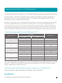
General Purpose Flow Bench, 5 to 500 SLM Procedures
Your Mesa General Purpose Flow Bench, 5 to 500 SLM utilizes different technologies to provide a stable gas flow.
By closing both ½” valves flow is directed through a needle valve capable of providing a stable flow in
the range of 5-50 SLm. The flow continues through a ¼” A/B valve and is diverted to either the DUT
(Device Under Test) or the Bios DryCal® Standard.
In addition to the needle valve, the Mesa 500 SLm Flow Bench has two sonic nozzles that provide a stable
flow source at higher flow rates, up to 500 SLm. By closing the ¼” valve, flow is directed through the
sonic nozzles and on through a ¾” A/B valve. By varying the upstream pressure, different flow rates can
be achieved by directing the flow through the 0.063” sonic nozzle, the 0.125” sonic nozzle, or both at the
same time. Adjust the inlet pressure using the regulator with the appropriate valve(s) open and running.
This table provides approximate flow rates at 760mmHg and 21.1 °C:
Input Pressure psi
Sonic Nozzles
0.063
0.125
Flow Rate slpm
X
30
X
75
X
290
X
365
X
35
X
82
X
325
X
400
X
40
X
90
X
360
X
445
X
45
X
50
100
X
390
X
490
X
110
X
420
MFC’s can be calibrated by connecting to the ½” flow port upstream of the valves and closing the ¼” valve
and both ½” valves. Use the regulator to set the proper inlet pressure for your DUT. Connect your Bios
DryCal® standard to the outlet of your DUT.
The following formula represents the MFC’s accuracy in comparison to your Bios DryCal®unit:
% Accuracy (full scale) = (DryCal® measurement – DUT reading) * 100 / DUT full scale %
Recalibration
No calibration is required for Mesa Gas Flow Benches.
16
Limited Warranty
The Bios DryCal Flow Bench is warranted to the original end user to be free from defects in materials
and workmanship under normal use and service for a period of one year from the date of purchase as
shown on the purchaser’s receipt. If the unit was purchased from an authorized reseller, a copy of an
invoice or packing slip showing the date of purchase may be required to obtain warranty service.
The obligation of Mesa Labs under this warranty shall be limited to repair or replacement (at our option), during the warranty period, of any part that proves defective in material or workmanship under
normal use and service, provided the product is returned to Mesa Labs, transportation charges prepaid.
Notwithstanding the foregoing, Mesa Labs shall have no liability to repair or replace any Mesa Labs
product:
1. That has been damaged following sale, including but not limited to damage resulting from improper
electrical voltages or currents, defacement, misuse, abuse, neglect, accident, fire, flood, terrorism, act
of God or use in violation of the instructions furnished by Mesa Labs;
2. When the serial number has been altered or removed; or,
3. That has been repaired, altered or maintained by any person or party other than Mesa Labs’ own
service facility or a Mesa authorized service center, should one be established.
This warranty is in lieu of all other warranties, and all other obligations or liabilities arising as a result of
any defect or deficiency of the product, whether in contract or in tort or otherwise. All other warranties,
expressed or implied, including any implied warranties of merchantability and fitness for a particular
purpose, are specifically excluded.
Mesa Labs
10 Park Place
Butler, NJ USA 07405
Phone: 973.492.8400
Toll Free: 800.663.4977
Fax: 303.484.4992
Email: [email protected]
Web: www.drycal.com
© 2014 Mesa Labs MK01-34 Rev E