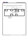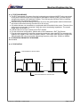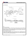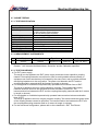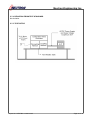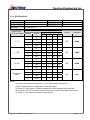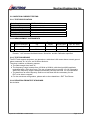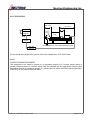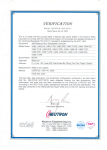
1
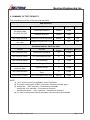
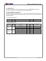
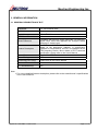
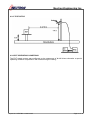
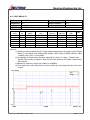
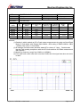
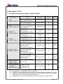
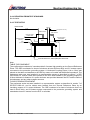
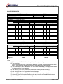
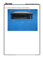
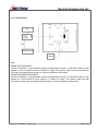
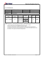
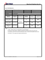
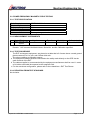
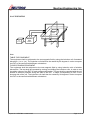
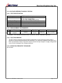
Neutron Engineering Inc.
Declaration
Neutron represents to the client that testing is done in accordance with standard procedures as applicable
and that test instruments used has been calibrated with the standards traceable to National Measurement
Laboratory (NML) of R.O.C., or National Institute of Standards and Technology (NIST) of U.S.A.
Neutron's reports apply only to the specific samples tested under conditions. It is manufacture’s
responsibility to ensure that additional production units of this model are manufactured with the identical
electrical and mechanical components. Neutron shall have no liability for any declarations, inferences or
generalizations drawn by the client or others from Neutron issued reports.
Neutron’s reports must not be used by the client to claim product endorsement by the authorities or any
agency of the Government.
This report is the confidential property of the client. As a mutual protection to the clients, the public and
Neutron-self, extracts from the test report shall not be reproduced except in full with Neutron’s authorized
written approval.
Neutron’s laboratory quality assurance procedures are in compliance with the ISO Guide 17025
requirements, and accredited by the conformity assessment authorities listed in this test report.
Limitation
For the use of the authority's logo is limited unless the Test Standard(s)/Scope(s)/Item(s) mentioned in this
test report is (are) included in the conformity assessment authorities acceptance respective.
Report No.: NEI-EMC-1-0703C143A
Page 2 of 48
Neutron Engineering Inc.
Table of Contents
Page
1 . CERTIFICATION
6
2 . SUMMARY OF TEST RESULTS
7
2.1 TEST FACILITY
8
2.2 MEASUREMENT UNCERTAINTY
8
3 . GENERAL INFORMATION
3.1 GENERAL DESCRIPTION OF EUT
3.2 DESCRIPTION OF TEST MODES
9
9
10
3.3 BLOCK DIAGRAM SHOWING THE CONFIGURATION OF SYSTEM TESTED 11
3.4 DESCRIPTION OF SUPPORT UNITS
4 . EMC EMISSION TEST
4.1
CONDUCTED EMISSION MEASUREMENT
4.1.1 POWER LINE CONDUCTED EMISSION
4.1.2 MEASUREMENT INSTRUMENTS LIST
4.1.3 TEST PROCEDURE
4.1.4 DEVIATION FROM TEST STANDARD
4.1.5 TEST SETUP
4.1.6 EUT OPERATING CONDITIONS
4.1.7 TEST RESULTS
4.2 RADIATED EMISSION MEASUREMENT
4.2.1 LIMITS OF RADIATED EMISSION MEASUREMENT
4.2.2 MEASUREMENT INSTRUMENTS LIST
4.2.3 TEST PROCEDURE
4.2.4 DEVIATION FROM TEST STANDARD
4.2.5 TEST SETUP
4.2.6 EUT OPERATING CONDITIONS
4.2.7 TEST RESULTS
5 . EMC IMMUNITY TEST
12
13
13
13
13
14
14
14
15
16
18
18
19
19
19
20
20
21
23
5.1 STANDARD COMPLIANCE/SEVERITY LEVEL/CRITERIA
23
5.2 GENERAL PERFORMANCE CRITERIA
24
5.3 GENERAL PERFORMANCE CRITERIA TEST SETUP
24
5.4 ESD TESTING
5.4.1 TEST SPECIFICATION
5.4.2 MEASUREMENT INSTRUMENTS
5.4.3 TEST PROCEDURE
5.4.4 DEVIATION FROM TEST STANDARD
25
25
25
25
26
Report No.: NEI-EMC-1-0703C143A
Page 3 of 48
Neutron Engineering Inc.
Table of Contents
5.4.5 TEST SETUP
5.4.6 TEST RESULTS
5.4.7 PHOTO(S) SHOWN THE LOCATION(S) OF ESD EVALUATED
Page
26
27
28
5.5 RS TESTING
5.5.1 TEST SPECIFICATION
5.5.2 MEASUREMENT INSTRUMENTS
5.5.3 TEST PROCEDURE
5.5.4 DEVIATION FROM TEST STANDARD
5.5.5 TEST SETUP
5.5.6 TEST RESULTS
29
29
29
29
29
30
31
5.6 EFT/BURST TESTING
5.6.1 TEST SPECIFICATION
5.6.2 MEASUREMENT INSTRUMENTS
5.6.3 TEST PROCEDURE
5.6.4 DEVIATION FROM TEST STANDARD
5.6.5 TEST SETUP
5.6.6 TEST RESULTS
32
32
32
32
32
33
34
5.7 SURGE TESTING
5.7.1 TEST SPECIFICATION
5.7.2 MEASUREMENT INSTRUMENTS
5.7.3 TEST PROCEDURE
5.7.4 DEVIATION FROM TEST STANDARD
5.7.5 TEST SETUP
5.7.6 TEST RESULTS
35
35
35
35
36
36
37
5.8 INJECTION CURRENT TESTING
5.8.1 TEST SPECIFICATION
5.8.2 MEASUREMENT INSTRUMENTS
5.8.3 TEST PROCEDURE
5.8.4 DEVIATION FROM TEST STANDARD
5.8.5 TEST SETUP
5.8.6 TEST RESULTS
38
38
38
38
38
39
40
5.9 POWER FREQUENCY MAGNETIC FIELD TESTING
5.9.1 TEST SPECIFICATION
5.9.2 MEASUREMENT INSTRUMENTS
5.9.3 TEST PROCEDURE
5.9.4 DEVIATION FROM TEST STANDARD
5.9.5 TEST SETUP
5.9.6 TEST RESULTS
41
41
41
41
41
42
43
5.10 VOLTAGE INTERRUPTION/DIPS TESTING
5.10.1 TEST SPECIFICATION
5.10.2 MEASUREMENT INSTRUMENTS
44
44
44
Report No.: NEI-EMC-1-0703C143A
Page 4 of 48
Neutron Engineering Inc.
Table of Contents
5.10.3 TEST PROCEDURE
5.10.4 DEVIATION FROM TEST STANDARD
5.10.5 TEST SETUP
5.10.6 TEST RESULTS
6 . EUT TEST PHOTO
Report No.: NEI-EMC-1-0703C143A
Page
44
44
45
46
47
Page 5 of 48
Neutron Engineering Inc.
1. CERTIFICATION
Equipment :
Brand Name :
Model Name :
Applicant:
Date of Test :
Te s t I t e m :
Sta n d a r d s :
3.5” SATA Mobile Rack
iStar
T-7-SA;T-7-M1
iStarUSA Inc.
Mar. 30, 2007 ~Apr. 04, 2007
ENGINEERING SAMPLE
EN 55022:1998+A1:2000+A2:2003 Class B
EN 55024:1998+A1: 2001+A2: 2003
IEC 61000-4-2: 2001
IEC 61000-4-3: 2002
IEC 61000-4-4: 2004
IEC 61000-4-5: 2001
IEC 61000-4-6: 2003+A1:2004
IEC 61000-4-8: 2001
IEC 61000-4-11: 2001
The above equipment has been tested and found compliance with the requirement of the relative
standards by Neutron Engineering Inc. EMC Laboratory.
The test data, data evaluation, and equipment configuration contained in our test report (Ref No.
NEI-EMC-1-0703C143A)were obtained utilizing the test procedures, test instruments, test sites
that has been accredited by the Authority of NVLAP and TAF according to the ISO-17025 quality
assessment standard and technical standard(s).
Report No.: NEI-EMC-1-0703C143A
Page 6 of 48
Neutron Engineering Inc.
2. SUMMARY OF TEST RESULTS
Test procedures according to the technical standards:
EMC Emission
Standard
Test Item
Limit
Judgment
Conducted Emission
Class B
PASS
Radiated Emission
Class B
PASS
EN 61000-3-2:2006
Harmonic Current Emission
Class A or D
N/A
N/A
EN 61000-3-3:1995
+A1: 2001
Voltage Fluctuations & Flicker
------
N/A
N/A
Judgment
Remark
EN 55022:1998
+A1:2000+A2:2003
Section
NOTE (2)
EMC Immunity
EN 55024:1998+A1: 2001+A2: 2003
Performance
Test Item
Criteria
IEC 61000-4-2:2001
Electrostatic Discharge
B
PASS
IEC 61000-4-3:2002
RF electromagnetic field
A
PASS
IEC 61000-4-4:2004
Fast transients
B
PASS
IEC 61000-4-5:2001
Surges
B
PASS
IEC 61000-4-6:
2003+A1:2004
Injected Current
A
PASS
IEC 61000-4-8:2001
Power Frequency Magnetic
Field
A
PASS
IEC 61000-4-11:2001
Volt. Interruptions Volt. Dips
B/C/C
PASS
NOTE (3)
Remark
NOTE:
(1) ” N/A” denotes test is not applicable in this Test Report.
(2) The power consumption of EUT is less than 75W and no Limits apply.
(3) Voltage dip: >95% reduction – Performance Criteria B
Voltage dip: 30% reduction – Performance Criteria C
Voltage Interruption: >95% reduction – Performance Criteria C
(4) For client’s request and manual description, the test will not be executed.
Report No.: NEI-EMC-1-0703C143A
Page 7 of 48
Neutron Engineering Inc.
2.1 TEST FACILITY
The test facilities used to collect the test data in this report is C01/OS02 at the location of
No.132-1, Lane 329, Sec. 2, Palain Road, Shijr City, Taipei, Taiwan.
2.2 MEASUREMENT UNCERTAINTY
The reported uncertainty of measurement y ± U,where expended uncertainty U is based on a
standard uncertainty multiplied by a coverage factor of k=2,providing a level of confidence of
approximately 95%。
A. Conducted Measurement :
Test Site
C01
Method
ANSI
Measurement Frequency Range
150 KHz ~ 30MHz
U,(dB)
1.94
NOTE
U,(dB)
NOTE
B. Radiated Measurement :
Test Site
Method
OS-01
ANSI
OS-02
ANSI
Measurement Frequency
Range
30MHz ~ 200MHz
30MHz ~ 200MHz
200MHz ~ 1,000MHz
200MHz ~ 1,000MHz
30MHz ~ 200MHz
30MHz ~ 200MHz
200MHz ~ 1,000MHz
200MHz ~ 1,000MHz
Report No.: NEI-EMC-1-0703C143A
Ant.
H/V
V
H
V
H
V
H
V
H
3.82
3.60
3.86
3.94
2.48
2.16
2.50
2.66
Page 8 of 48
Neutron Engineering Inc.
3. GENERAL INFORMATION
3.1 GENERAL DESCRIPTION OF EUT
Equipment
3.5” SATA Mobile Rack
Brand Name
iStar
Model Name
T-7-SA;T-7-M1
OEM Brand/Model Name N/A
Compared with previous report (NEI-EMC-1-0703C143),
Model Difference
Model name, brand and applicant are changed. Model
difference is model name.
The EUT is a 3.5” SATA Mobile Rack.
Based on the application, features, or specification
exhibited in User's Manual, the EUT is considered as an
Product Description
ITE/Computing Device. More details of EUT technical
specification, please refer to the User's Manual.
Power Source
Supplied from PC Power.
Power Rating
N/A
Connecting I/O Port(s)
Please refer to the User's Manual
Products Covered
N/A
EUT Modification(s)
N/A
Note:
1. For a more detailed features description, please refer to the manufacturer’s specifications
or the User's Manual.
Report No.: NEI-EMC-1-0703C143A
Page 9 of 48
Neutron Engineering Inc.
3.2 DESCRIPTION OF TEST MODES
To investigate the maximum EMI emission characteristics generated from EUT, the test
system was pre-scanning tested base on the consideration of following EUT operation mode
or test configuration mode which possible have effect on EMI emission level. Each of these
EUT operation mode(s) or test configuration mode(s) mentioned above was evaluated
respectively.
Pretest Mode
Description
Mode 1
SYSTEM LOAD
The EUT system operated these modes were found to be the worst case during the
pre-scanning test as Following:
For Conducted / Radiated Test
Final Test Mode
Description
Mode 1
SYSTEM LOAD
For EMS Test
Final Test Mode
Description
Mode 1
SYSTEM LOAD
Report No.: NEI-EMC-1-0703C143A
Page 10 of 48
Neutron Engineering Inc.
3.3 BLOCK DIAGRAM SHOWING THE CONFIGURATION OF SYSTEM TESTED
C-3
C-2
E-5
Printer
C-1
E-1
EUT
E-2
PC
E-4
Monitor
C-4
E-6
Keyboard
E-3
Modem
C-5
E-7
Mouse
C-1 Interface Cable
C-2 VGA Cable
C-3 Centronics Cable
C-4 Data Cable
C-5 DataCable
Report No.: NEI-EMC-1-0703C143A
Page 11 of 48
Neutron Engineering Inc.
3.4 DESCRIPTION OF SUPPORT UNITS
The EUT has been tested as an independent unit together with other necessary accessories or
support units. The following support units or accessories were used to form a representative test
configuration during the tests.
Item
Mfr/Brand
Model/Type No.
FCC ID
Series No.
Note
iStar
T-7-SA
DOC
N/A
EUT
E-2
Equipment
3.5” SATA
Mobile Rack
PC
IBM
8434-INV
DOC
99FCL27
E-3
Modem
ACEEX
DM-1414V
DOC
8041708
E-4
Monitor
HITACHI
CM753ET
DOC
T8L000003
E-5
Printer
SII
DPU-414
DOC
1045105A
E-6
PS/2 K/B
Dell
M-SAW34
DOC
N/A
E-7
USB Mouse
Dell
M-UVDEL1
DOC
23-271883
E-1
Item
C-1
C-2
C-3
C-4
C-5
Shielded Type
YES
YES
YES
YES
YES
Ferrite Core
NO
YES
NO
NO
NO
Length
1.8M
1.8M
1.5M
1.5M
1.8M
Note
Note:
(1)
(2)
The support equipment was authorized by Declaration of Conformity.
For detachable type I/O cable should be specified the length in cm in『Length』column.
Report No.: NEI-EMC-1-0703C143A
Page 12 of 48
Neutron Engineering Inc.
4. EMC EMISSION TEST
4.1 CONDUCTED EMISSION MEASUREMENT
4.1.1 POWER LINE CONDUCTED EMISSION (FREQUENCY RANGE 150KHZ-30MHZ)
FREQUENCY (MHz)
Class A (dBuV)
Class B (dBuV)
Quasi-peak
Average
Quasi-peak
Average
0.15 -0.5
79.00
66.00
66 - 56 *
56 - 46 *
0.50 -5.0
73.00
60.00
56.00
46.00
5.0 -30.0
73.00
60.00
60.00
50.00
Note:
(1) The tighter limit applies at the band edges.
(2) The limit of " * " marked band means the limitation decreases linearly with the
logarithm of the frequency in the range.
4.1.2 MEASUREMENT INSTRUMENTS LIST
Item Kind of Equipment
LISN
1
Manufacturer
Rolf Heine
Type No.
NNB-2/16Z
Serial No.
98053
Calibrated until
Dec. 18, 2007
2
LISN
EMCO
3816/2
00042991
Jan. 08, 2008
3
Pulse Limiter
Electro-Metrics
EM-7600
112644
Nov. 28, 2007
4
50Ω Terminator
N/A
N/A
N/A
May.11, 2007
5
Test Cable
N/A
C01
N/A
Nov. 28, 2007
6
EMI Test Receiver
R&S
ESCI
100082
Jan. 31, 2008
Remark: ” N/A” denotes No Model Name, Serial No. or No Calibration specified.
Report No.: NEI-EMC-1-0703C143A
Page 13 of 48
Neutron Engineering Inc.
4.1.3 TEST PROCEDURE
a. The EUT was placed 0.8 meters from the horizontal ground plane with EUT being connected
to the power mains through a line impedance stabilization network (LISN). All other support
equipments powered from additional LISN(s). The LISN provide 50 Ohm/ 50uH of coupling
impedance for the measuring instrument.
b. Interconnecting cables that hang closer than 40 cm to the ground plane shall be folded back
and forth in the center forming a bundle 30 to 40 cm long.
c. I/O cables that are not connected to a peripheral shall be bundled in the center. The end of the
cable may be terminated, if required, using the correct terminating impedance. The overall
length shall not exceed 1 m.
d. LISN at least 80 cm from nearest part of EUT chassis.
e. For the actual test configuration, please refer to the related Item –EUT Test Photos.
f. First the whole spectrum of emission caused by equipment under test(EUT) is recorded with
Detector set to peak. Peak value recorded in table if the margin from QP Limit is larger than
2dB,otherwise,QP value is recorded, Measuring frequency range from 150KHz to 30MHz.
4.1.4 DEVIATION FROM TEST STANDARD
No deviation
4.1.5 TEST SETUP
Vertical Reference Ground Plane
40 cm
EUT
Test Receiver
80 cm
LISN
Horizontal Reference Ground Plane
Report No.: NEI-EMC-1-0703C143A
Page 14 of 48
Neutron Engineering Inc.
4.1.6 EUT OPERATING CONDITIONS
The EUT exercise program used during radiated and/or conducted emission measurement was
designed to exercise the various system components in a manner similar to a typical use. The
program contained on a PC hard disk and is auto-starting on power-up. Once loaded, the program
sequentially exercises each system component in turn. The sequence used is:
1. Read (write) from (to) mass storage device.
2. Send " H " pattern to video port device (Monitor).
3. Send " H " pattern to parallel port device (Printer).
4. Send " H " pattern to serial port device (Modem).
5. EUT send messages to PC.
6. Repeated from 2 to 5 continuously.
As the keyboard and mouse are strictly input devices, no data is transmitted to (from) them during
test. They are, however, continuously scanned for data input activity.
Report No.: NEI-EMC-1-0703C143A
Page 15 of 48
Neutron Engineering Inc.
4.1.7 TEST RESULTS
E.U.T :
Temperature :
Pressure :
Test Mode :
Freq.
(MHz)
0.15
0.19
0.25
0.32
6.10
11.10
3.5” SATA Mobile Rack
25℃
1009 hPa
SYSTEM LOAD
Terminal
L/N
Line
Line
Line
Line
Line
Line
Measured(dBuV)
QP-Mode AV-Mode
39.32
*
36.02
*
28.86
*
25.70
*
31.68
*
32.49
*
Model Name :
T-7-SA
Relative Humidity : 65 %
Test Voltage :
AC 230V/50Hz
Limits(dBuV)
QP-Mode AV-Mode
65.77
55.77
64.01
54.01
61.78
51.78
59.83
49.83
60.00
50.00
60.00
50.00
Margin
(dB)
-26.45
-27.99
-32.92
-34.13
-28.32
-27.51
Note
(QP)
(QP)
(QP)
(QP)
(QP)
(QP)
Remark
:
(1) Reading in which marked as QP means measurements by using are Quasi-Peak Mode with
Detector BW=9KHz;SPA setting in RBW=10KHz,VBW =10KHz, Swp. Time = 0.3 sec./MHz。
Reading in which marked as AV means measurements by using are Average Mode with
instrument setting in RBW=10KHz,VBW=10KHz, Swp. Time =0.3 sec./MHz。
(2) All readings are QP Mode value unless otherwise stated AVG in column of『Note』
. If the QP
Mode Measured value compliance with the QP Limits and lower than AVG Limits, the EUT
shall be deemed to meet both QP & AVG Limits and then only QP Mode was measured,
but AVG Mode didn‘t perform。In this case, a “ * ” marked in AVG Mode column of
Interference Voltage Measured。
(3) Measuring frequency range from 150KHz to 30MHz。
Report No.: NEI-EMC-1-0703C143A
Page 16 of 48
Neutron Engineering Inc.
E.U.T :
Temperature :
Pressure :
Test Mode :
Freq.
(MHz)
0.15
0.19
0.25
6.10
11.00
14.70
3.5” SATA Mobile Rack
25℃
1009 hPa
SYSTEM LOAD
Terminal
L/N
Neutral
Neutral
Neutral
Neutral
Neutral
Neutral
Measured(dBuV)
QP-Mode AV-Mode
37.30
*
34.66
*
28.47
*
32.02
*
31.71
*
33.40
*
Model Name :
T-7-SA
Relative Humidity : 65 %
Test Voltage :
AC 230V/50Hz
Limits(dBuV)
QP-Mode AV-Mode
65.85
55.85
64.23
54.23
61.68
51.68
60.00
50.00
60.00
50.00
60.00
50.00
Margin
(dB)
-28.55
-29.57
-33.21
-27.98
-28.29
-26.60
Note
(QP)
(QP)
(QP)
(QP)
(QP)
(QP)
Remark
:
(1) Reading in which marked as QP means measurements by using are Quasi-Peak Mode with
Detector BW=9KHz;SPA setting in RBW=10KHz,VBW =10KHz, Swp. Time = 0.3 sec./MHz。
Reading in which marked as AV means measurements by using are Average Mode with
instrument setting in RBW=10KHz,VBW=10KHz, Swp. Time =0.3 sec./MHz。
(2) All readings are QP Mode value unless otherwise stated AVG in column of『Note』
. If the QP
Mode Measured value compliance with the QP Limits and lower than AVG Limits, the EUT
shall be deemed to meet both QP & AVG Limits and then only QP Mode was measured,
but AVG Mode didn‘t perform。In this case, a “ * ” marked in AVG Mode column of
Interference Voltage Measured。
(3) Measuring frequency range from 150KHz to 30MHz。
Report No.: NEI-EMC-1-0703C143A
Page 17 of 48
Neutron Engineering Inc.
4.2 RADIATED EMISSION MEASUREMENT
4.2.1 LIMITS OF RADIATED EMISSION MEASUREMENT
FREQUENCY (MHz)
30 – 230
Class A (at 10m)
Class B (at 10m)
dBuV/m
dBuV/m
40
30
230 – 1000
47
37
Notes:
(1) The limit for radiated test was performed according to as following:
CISPR 22/ FCC PART 15B /ICES-003.
(2) The tighter limit applies at the band edges.
(3) Emission level (dBuV/m)=20log Emission level (uV/m).
Report No.: NEI-EMC-1-0703C143A
Page 18 of 48
Neutron Engineering Inc.
4.2.2 MEASUREMENT INSTRUMENTS LIST
Item Kind of Equipment
Test Cable
1
Manufacturer
N/A
Type No.
CISPR 14
Serial No.
N/A
Calibrated until
Oct. 01, 2007
2
EMI Test Receiver
R&S
ESCI
100082
Jan. 31, 2008
3
Absorbing Clamp
Schwarzbeck
MDS-21
03195
Jun. 28, 2007
Remark: ” N/A” denotes No Model Name / Serial No. and No Calibration specified.
4.2.3 TEST PROCEDURE
a. The measuring distance of at 10 m shall be used for measurements at frequency up to 1GHz.
For frequencies above 1GHz, any suitable measuring distance may be used.
b. The EUT was placed on the top of a rotating table 0.8 meters above the ground at a 3m or 10
meter open area test site. The table was rotated 360 degrees to determine the position of the
highest radiation.
c. The height of the equipment or of the substitution antenna shall be 0.8 m; the height of the test
antenna shall vary between 1 m to 4 m. Both horizontal and vertical polarizations of the
antenna are set to make the measurement.
d. The initial step in collecting radiated emission data is a spectrum analyzer peak detector mode
pre-scanning the measurement frequency range. Significant peaks are then marked and then
Quasi Peak detector mode re-measured.
e. If the Peak Mode measured value compliance with and lower than Quasi Peak Mode Limit, the
EUT shall be deemed to meet QP Limits and then no additional QP Mode measurement
performed.
f. For the actual test configuration, please refer to the related Item –EUT Test Photos.
4.2.4 DEVIATION FROM TEST STANDARD
No deviation
Report No.: NEI-EMC-1-0703C143A
Page 19 of 48
Neutron Engineering Inc.
4.2.5 TEST SETUP
4.2.6 EUT OPERATING CONDITIONS
The EUT tested system was configured as the statements of 4.1.6 Unless otherwise a special
operating condition is specified in the follows during the testing.
Report No.: NEI-EMC-1-0703C143A
Page 20 of 48
Neutron Engineering Inc.
4.2.7 TEST RESULTS
E.U.T :
Temperature :
Pressure :
Test Mode :
Freq.
(MHz)
30.00
43.58
431.58
456.80
596.42
871.96
3.5” SATA Mobile Rack
22℃
1009 hPa
SYSTEM LOAD
Ant.
H/V
V
V
V
V
V
V
Model Name :
Relative Humidity :
Test Voltage :
Reading(RA) Corr.Factor(CF) Measured(FS)
(dBuV)
(dB)
(dBuV/m)
23.92
30.81
-8.19
17.60
31.15
-6.33
16.80
25.51
-6.63
19.27
27.43
-8.16
22.67
27.92
-9.05
27.78
9.03
25.42
T-7-SA
56%
AC 230V/50Hz
Limits(QP)
(dBuV/m)
30.00
30.00
37.00
37.00
37.00
Margin
(dB)
- 6.08
- 12.40
- 20.20
- 17.73
- 14.33
37.00
- 11.58
Note
(QP)
Remark:
(1) Reading in which marked as QP or Peak means measurements by using are Quasi-Peak
Mode or Peak Mode with Detector BW=120KHz;SPA setting in RBW=120KHz, VBW
=120KHz, Swp. Time = 0.3 sec./MHz。
(2) All readings are Peak unless otherwise stated QP in column of『Note』. Peak denotes
that the Peak reading compliance with the QP Limits and then QP Mode measurement
didn‘t perform。
(3) Measuring frequency range from 30MHz to 1000MHz。
(4) If the peak scan value lower limit more than 20dB, then this signal data does not show
in table。
Report No.: NEI-EMC-1-0703C143A
Page 21 of 48
Neutron Engineering Inc.
E.U.T :
Temperature :
Pressure :
Test Mode :
Freq.
(MHz)
456.80
526.64
598.42
757.50
798.24
891.36
3.5” SATA Mobile Rack
22℃
1009 hPa
SYSTEM LOAD
Ant.
H/V
H
H
H
H
H
H
Model Name :
Relative Humidity :
Test Voltage :
Reading(RA) Corr.Factor(CF) Measured(FS)
(dBuV)
(dB)
(dBuV/m)
17.79
25.95
-8.19
19.74
26.35
-6.33
30.69
35.94
-6.63
23.01
26.43
-8.16
22.26
25.46
-9.05
32.24
9.03
30.40
T-7-SA
50 %
AC 230V/50Hz
Limits(QP)
(dBuV/m)
37.00
37.00
37.00
37.00
37.00
37.00
Margin
(dB)
- 19.21
- 17.26
- 6.31
- 13.99
- 14.74
-
Note
(QP)
6.60
Remark:
(1) Reading in which marked as QP or Peak means measurements by using are Quasi-Peak
Mode or Peak Mode with Detector BW=120KHz;SPA setting in RBW=120KHz, VBW
=120KHz, Swp. Time = 0.3 sec./MHz。
(2) All readings are Peak unless otherwise stated QP in column of『Note』. Peak denotes
that the Peak reading compliance with the QP Limits and then QP Mode measurement
didn‘t perform。
(3) Measuring frequency range from 30MHz to 1000MHz。
(4) If the peak scan value lower limit more than 20dB, then this signal data does not show
in table。
Report No.: NEI-EMC-1-0703C143A
Page 22 of 48
Neutron Engineering Inc.
5. EMC IMMUNITY TEST
5.1 STANDARD COMPLIANCE/SEVERITY LEVEL/CRITERIA
Tests
Standard No.
1. ESD
IEC/EN 61000-4-2
2. RS
IEC/EN 61000-4-3
3. EFT/Burst
IEC/EN 61000-4-4
4. Surges
IEC/EN 61000-4-5
5 Injected Current
IEC/EN 61000-4-6
6. Power Frequency
Magnetic Field
IEC/EN 61000-4-8
7. Volt. Interruptions
Volt. Dips
IEC/EN 61000-4-11
TEST SPECIFICATION
Level
8KV air discharge
4KV contact discharge
4KV HCP discharge
4KV VCP discharge
80 MHz to 1000 MHz
3V/m(rms), 1 KHz, 80%,
AM modulated
1.0KV(peak)
5/50ns Tr/Th
5KHz Repetition Freq.
0.5 KV(peak)
5/50ns Tr/Th
5KHz Repetition Freq.
1 KV(5P/5N)
1.2/50(8/20) Tr/Th us
2 KV(5P/5N)
1.2/50(8/20) Tr/Th us
0.15 MHz to 80 MHz
3V(rms), 1KHz 80%,
AM Modulated
150Ω source impedance
0.15 MHz to 80 MHz
3V(rms), 1KHz 80%,
AM Modulated
150Ω source impedance
0.15 MHz to 80 MHz
3V(rms), 1KHz 80%,
AM Modulated
150Ω source impedance
50 Hz, 1A/m
Voltage dip>95%
Voltage dip 30%
Interruption>95%
Test Mode
Test Ports
Perform.
Criteria
Direct Mode
B
Indirect Mode
B
Enclosure
A
Power Supply
Port
B
CTL/Signal
Data Line
Port
B
L-N
B
L-PE
N-PE
B
CTL/Signal Port
A
AC Power Port
A
DC Power Port
A
Enclosure
A
Remark
N/A
(2)
N/A
(2)
N/A
B
AC Power Port
C
C
* Remark:
N/A : denotes test is not applicable in this Test Report
(1) : The EUT is a battery operating device and no any other cable connection to PC device.
(2) : Applicable only to cables which according to the manufacturer’s specification supports
communication on cables lengths greater than 3 m.
(3) : Applicable only to equipment containing devices susceptible to magnetic fields
Report No.: NEI-EMC-1-0703C143A
Page 23 of 48
Neutron Engineering Inc.
5.2 GENERAL PERFORMANCE CRITERIA
According to EN55024 standard, the general performance criteria as following:
The equipment shall continue to operate as intended without operator
intervention. No degradation of performance or loss of function is allowed below
a performance level specified by the manufacturer when the equipment is used
as intended. The performance level may be replaced by a permissible loss of
performance.
Criterion A
If the minimum performance level or the permissible performance loss is not
specified by the manufacturer, then either of these may be derived from the
product description and documentation, and by what the user product
description and documentation, and by what the user may reasonably expect
from the equipment if used as intended.
After the test, the equipment shall continue to operate as intended without
operator
Intervention. No degradation of performance or loss of function is allowed, after
the application of the phenomenon below a performance level specified by the
manufacturer, when the equipment is used as intended. The performance level
may be replaced by a permissible loss of performance.
Criterion B
During the test, degradation of performance is allowed. However, no change of
operating state if stored data allowed to persist after the test. If the minimum
performance level (or the permissible performance loss ) is not specified by the
manufacturer, then either of these may be derived from the product description
and documentation, and by what the user may reasonably expect from the
equipment if used as intended.
Loss of function is allowed, provided the function is self-recoverable, or can be
restored by the operation of the controls by the user in accordance with the
Criterion C manufacturer’s instructions.
Functions, and/or information stored in non-volatile memory, or protected by a
battery backup, shall not be lost.
5.3 GENERAL PERFORMANCE CRITERIA TEST SETUP
The EUT tested system was configured as the statements of 4.1.6 Unless otherwise a special
operating condition is specified in the follows during the testing.
Report No.: NEI-EMC-1-0703C143A
Page 24 of 48
Neutron Engineering Inc.
5.4 ESD TESTING
5.4.1 TEST SPECIFICATION
Basic Standard:
Discharge Impedance:
Required Performance
Discharge Voltage:
Polarity:
Number of Discharge:
Discharge Mode:
Discharge Period:
IEC/EN 61000-4-2
330 ohm / 150 pF
B
Air Discharge:2kV/4kV/8kV (Direct)
Contact Discharge:2kV/4kV (Direct/Indirect)
Positive & Negative
Air Discharge: min. 20 times at each test point
Contact Discharge: min. 200 times in total
Single Discharge
1 second minimum
5.4.2 MEASUREMENT INSTRUMENTS
Item Kind of Equipment
ESD Simulator
1
Manufacturer
Thermo
Type No.
MZ-15/EC
Serial No.
0502184
Calibrated until
Nov, 26, 2007
Remark: ” N/A” denotes No Model Name / Serial No. and No Calibration specified.
5.4.3 TEST PROCEDURE
The test generator necessary to perform direct and indirect application of discharges to the EUT in
the following manner:
a. Contact discharge was applied to conductive surfaces and coupling planes of the EUT.
During the test, it was performed with single discharges. For the single discharge time
between successive single discharges was at least 1 second. The EUT shall be exposed to at
least 200 discharges, 100 each at negative and positive polarity, at a minimum of four test
points. One of the test points shall be subjected to at least 50 indirect discharges to the center
of the front edge of the horizontal coupling plane. The remaining three test points shall each
receive at least 50 direct contact discharges.
If no direct contact test points are available, then at least 200 indirect discharges shall be
applied in the indirect mode. Test shall be performed at a maximum repetition rate of one
discharge per second.
Vertical Coupling Plane (VCP):
The coupling plane, of dimensions 0.5m x 0.5m, is placed parallel to, and positioned at a
distance 0.1m from, the EUT, with the Discharge Electrode touching the coupling plane.
The four faces of the EUT will be performed with electrostatic discharge.
Horizontal Coupling Plane (HCP):
The coupling plane is placed under to the EUT. The generator shall be positioned vertically at
a distance of 0.1m from the EUT, with the Discharge Electrode touching the coupling plane.
The four faces of the EUT will be performed with electrostatic discharge.
b. Air discharges at insulation surfaces of the EUT.
It was at least ten single discharges with positive and negative at the same selected point.
c. For the actual test configuration, please refer to the related Item –EUT Test Photos.
Report No.: NEI-EMC-1-0703C143A
Page 25 of 48
Neutron Engineering Inc.
5.4.4 DEVIATION FROM TEST STANDARD
No deviation
5.4.5 TEST SETUP
Nearest Wall
10 cm
1m
VCP (50 cm x 50 cm)
ESD Generator
ESD Generator
Discharge Return
Cable to GRP
Discharge Return
Cable to GRP
To AC Main
Isolation Support
(0.5mm)
EUT
HCP
(1.6m x 0. 8m)
470 KO
Non-Conductive T able
80 cm
470 KO
Ground Reference Plane (GRP) Bonded to PE
Note:
TABLE-TOP EQUIPMENT
The configuration consisted of a wooden table 0.8 meters high standing on the Ground Reference
Plane. The GRP consisted of a sheet of aluminum at least 0.25mm thick, and 2.5 meters square
connected to the protective grounding system. A Horizontal Coupling Plane (1.6m x 0.8m) was
placed on the table and attached to the GRP by means of a cable with 940k total impedance. The
equipment under test, was installed in a representative system as described in section 7 of IEC
/EN 61000-4-2, and its cables were placed on the HCP and isolated by an insulating support of
0.5mm thickness. A distance of 1-meter minimum was provided between the EUT and the walls of
the laboratory and any other metallic structure.
FLOOR-STANDING EQUIPMENT
The equipment under test was installed in a representative system as described in section 7 of
IEC/EN 61000-4-2, and its cables were isolated from the Ground Reference Plane by an
insulating support of 0.1-meter thickness. The GRP consisted of a sheet of aluminum that is at
least 0.25mm thick, and 2.5meters square connected to the protective grounding system and
extended at least 0.5 meters from the EUT on all sides.
Report No.: NEI-EMC-1-0703C143A
Page 26 of 48
Neutron Engineering Inc.
5.4.6 TEST RESULTS
E.U.T :
Temperature :
Pressure :
Test Mode :
3.5” SATA Mobile Rack
25℃
1015 hPa
SYSTEM LOAD
Mode
Location
1
2
3
4
5
6
7
8
9
10
Criteria
Result
Judgment
2KV
P
N
A
A
A
A
A
A
A
A
A
A
Judgment
15KV
P
N
P
2KV
N
B
A
PASS
Mode
Location
1
2
3
4
Criteria
Result
Air Discharge
4KV
8KV
P
N
P
N
A
A
A
A
A
A
A
A
A
A
A
A
A
A
A
A
A
A
A
A
Model Name :
T-7-SA
Relative Humidity : 40%
Test Voltage :
AC 230V/50Hz
2KV
P
N
A
A
A
A
A
A
A
A
HCP Discharge
4KV
6KV
P
N
P
N
A
A
A
A
A
A
A
A
B
A
PASS
Contact
4KV
P
N
Discharge
6KV
8KV
P
N
P
N
B
N/A
N/A
8KV
P
N
2KV
P
N
A
A
A
A
A
A
A
A
VCP Discharge
4KV
6KV
P
N
P
N
A
A
A
A
A
A
A
A
B
A
8KV
P
N
PASS
Note:
1) P/N denotes the Positive/Negative polarity of the output voltage.
2) Test condition:
Direct / Indirect (HCP/VCP) discharges: Minimum 50 times (Positive/Negative) at each
point. Air discharges: Minimum 10 times (Positive/Negative) at each point.
3) Test location(s) in which discharge (Air and contact discharge) to be applied illustrated
by photos shown in next page(s)
4) The Indirect (HCP/VCP) discharges description of test point as following:
1.left side 2.right side 3.front side 4.rear side
5) N/A - denotes test is not applicable in this test report
6) Criteria A: There was no change operated with initial operating during the test.
7) Criteria B: The EUT function loss during the test, but self-recoverable after the test.
8) Criteria C: The system shut down during the test.
Report No.: NEI-EMC-1-0703C143A
Page 27 of 48
Neutron Engineering Inc.
5.4.7 PHOTO(S) SHOWN THE LOCATION(S) OF ESD EVALUATED
Report No.: NEI-EMC-1-0703C143A
Page 28 of 48
Neutron Engineering Inc.
5.5 RS TESTING
5.5.1 TEST SPECIFICATION
Basic Standard:
Required Performance
Frequency Range:
Field Strength:
Modulation:
Frequency Step:
Polarity of Antenna:
Test Distance:
Antenna Height:
Dwell Time:
IEC/EN 61000-4-3
A
80 MHz - 1000 MHz
3 V/m
1kHz Sine Wave, 80%, AM Modulation
1% of fundamental
Horizontal and Vertical
3m
1.5 m
at least 3 seconds
5.5.2 MEASUREMENT INSTRUMENTS
Item Kind of Equipment
Signal Generator
1
Manufacturer
R&S
Type No.
SMT 06
Serial No.
832080/007
Calibrated until
Jul, 26, 2007
2
Log-Bicon Antenna
Schwarzbeck
VULB9161
4022
Aug, 16, 2007
3
Power Amplifier
AR
150W1000M1
320946
Sep, 24. 2008
Remark: ” N/A” denotes No Model Name / Serial No. and No Calibration specified.
5.5.3 TEST PROCEDURE
The EUT and support equipment, which are placed on a table that is 0.8 meter above ground and
the testing was performed in a fully-anechoic chamber.
The testing distance from antenna to the EUT was 3 meters.
The other condition as following manner:
a. The field strength level was 3V/m.
b. The frequency range is swept from 80 MHz to 1000 MHz, with the signal 80%amplitude
modulated with a 1kHz sine wave. The rate of sweep did not exceed 1.5x 10⁻³ decade/s.
Where the frequency range is swept incrementally, the step size was 1% of fundamental.
c. Sweep Frequency 900 MHz, with the Duty Cycle:1/8 and Modulation: Pulse 217 Hz(if
applicable)
d. The dwell time at each frequency shall be not less than the time necessary for the
EUT to be able to respond.
e. The test was performed with the EUT exposed to both vertically and horizontally
polarized fields on each of the four sides.
f. For the actual test configuration, please refer to the related Item –EUT Test Photos.
5.5.4 DEVIATION FROM TEST STANDARD
No deviation
Report No.: NEI-EMC-1-0703C143A
Page 29 of 48
Neutron Engineering Inc.
5.5.5 TEST SETUP
Note:
TABLE-TOP EQUIPMENT
The EUT installed in a representative system as described in section 7 of IEC/EN 61000-4-3 was
placed on a non-conductive table 0.8 meters in height. The system under test was connected to
the power and signal wire according to relevant installation instructions.
FLOOR-STANDING EQUIPMENT
The EUT installed in a representative system as described in section 7 of IEC/EN 61000-4-3 was
placed on a non-conductive wood support 0.1 meters in height. The system under test was
connected to the power and signal wire according to relevant installation instructions.
Report No.: NEI-EMC-1-0703C143A
Page 30 of 48
Neutron Engineering Inc.
5.5.6 TEST RESULTS
E.U.T :
Temperature :
Pressure :
Test Mode :
3.5” SATA Mobile Rack
22℃
1015 hPa
SYSTEM LOAD
Model Name :
T-7-SA
Relative Humidity : 50%
Test Voltage :
AC 230V/50Hz
Frequency Range
RF Field
R.F.
(MHz)
Position
Field Strength
3 V/m (rms)
80MHz - 1000MHz
H/V
AM Modulated
1000Hz, 80%
Azimuth
Perform.
Criteria
Results Judgment
0
90
180
A
A
PASS
270
Note:
1) P/N denotes the Positive/Negative polarity of the output voltage.
2) N/A - denotes test is not applicable in this test report.
3) Criteria A: There was no change operated with initial operating during the test.
4) Criteria B: The EUT function loss during the test, but self-recoverable after the test.
5) Criteria C: The system shut down during the test.
Report No.: NEI-EMC-1-0703C143A
Page 31 of 48
Neutron Engineering Inc.
5.6 EFT/BURST TESTING
5.6.1 TEST SPECIFICATION
Basic Standard:
Required Performance
Test Voltage :
Polarity:
Impulse Frequency:
Impulse Wave shape :
Burst Duration:
Burst Period:
Test Duration:
IEC/EN 61000-4-4
B
Power Line: 1 kV
Signal/Control Line: 0.5 KV
Positive & Negative
5 kHz
5/50 ns
15 ms
300 ms
Not less than 1 min.
5.6.2 MEASUREMENT INSTRUMENTS
Item Kind of Equipment
1
Manufacturer
Type No.
Serial No.
Calibrated until
Thermo
EMCPRO PLUS
0502176
Dec. 10, 2007
EMC Immunity Test
System
Remark: ” N/A” denotes No Model Name / Serial No. and No Calibration specified.
5.6.3 TEST PROCEDURE
The EUT and support equipment(s) are placed on a table that is 0.8 meter high above a metal
ground plane and should be located 0.1m+/-0.01m high above the Ground Reference Plane
(1m*1m min. and 0.65mm thick min).
The other condition as following manner:
a. The length of power cord between the coupling device and the EUT should not exceed 1
meter.
b. Both positive and negative polarity discharges were applied.
c. The duration time of each test sequential was 1 minute
d. For the actual test configuration, please refer to the related Item –EUT Test Photos.
5.6.4 DEVIATION FROM TEST STANDARD
No deviation
Report No.: NEI-EMC-1-0703C143A
Page 32 of 48
Neutron Engineering Inc.
5.6.5 TEST SETUP
Note:
TABLE-TOP EQUIPMENT
The configuration consisted of a wooden table (0.8m high) standing on the Ground Reference
Plane and should be located 0.1m+/-0.01m above the Ground Reference Plane. The GRP
consisted of a sheet of aluminum (at least 0.25mm thick and 2.5m square) connected to the
protective grounding system. A minimum distance of 0.5m was provided between the EUT and the
walls of the laboratory or any other metallic structure.
FLOOR-STANDING EQUIPMENT
The EUT installed in a representative system as described in section 7 of IEC/EN 61000-4-4 and
its cables, were isolated from the Ground Reference Plane by an insulating support that is
0.1-meter thick. The GRP consisted of a sheet of aluminum (at least 0.25mm thick and 2.5m
square) connected to the protective grounding system.
Report No.: NEI-EMC-1-0703C143A
Page 33 of 48
Neutron Engineering Inc.
5.6.6 TEST RESULTS
E.U.T :
Temperature :
Pressure :
Test Mode :
Mode
3.5” SATA Mobile Rack
22℃
1015 hPa
SYSTEM LOAD
( V ) AC Power Line
Test Level
Port(s)
Line (L)
Neutral (N)
Ground (PE)
Signal/Control
Line
Model Name :
T-7-SA
Relative Humidity : 50%
Test Voltage :
AC 230V/50Hz
(
) DC Power Line
1KV
(
) Signal/Control Line
0.5KV
0.5KV
Polarity
Results
Polarity
Results
Polarity
P
A
P
P
N
A
N
N
P
A
P
P
N
A
N
N
P
A
P
P
N
A
N
N
P
P
P
N
N
N
Results
Criteria
B
B
B
Result
A
N/A
N/A
Judgment
PASS
N/A
N/A
Note:
1) P/N denotes the Positive/Negative polarity of the output voltage.
2) N/A - denotes test is not applicable in this test report
3) Criteria A: There was no change operated with initial operating during the test.
4) Criteria B: The EUT function loss during the test, but self-recoverable after the test.
5) Criteria C: The system shut down during the test.
Report No.: NEI-EMC-1-0703C143A
Page 34 of 48
Neutron Engineering Inc.
5.7 SURGE TESTING
5.7.1 TEST SPECIFICATION
Basic Standard:
Required Performance
Wave-Shape:
Test Voltage :
Surge Input/Output:
Generator Source:
Impedance:
Polarity:
Phase Angle:
Pulse Repetition Rate:
Number of Tests:
IEC/EN 61000-4-5
B
Combination Wave
1.2/50 us Open Circuit Voltage
8 /20 us Short Circuit Current
Power Line:0.5 kV, 1 kV, 2 kV
L1-L2, L1-PE, L2-PE
2 ohm between networks
12 ohm between network and ground
Positive/Negative
0 /90/180/270
1 time / min. (maximum)
5 positive and 5 negative at selected points
5.7.2 MEASUREMENT INSTRUMENTS
Item Kind of Equipment
1
Manufacturer
Type No.
Serial No.
Calibrated until
Thermo
EMCPRO PLUS
0502176
Dec. 10, 2007
EMC Immunity Test
System
Remark: ” N/A” denotes No Model Name / Serial No. and No Calibration specified.
5.7.3 TEST PROCEDURE
a. For EUT power supply:
The surge is to be applied to the EUT power supply terminals via the capacitive coupling
network. Decoupling networks are required in order to avoid possible adverse effects on
equipment not under test that may be powered by the same lines, and to provide sufficient
decoupling impedance to the surge wave. The power cord between the EUT and the
coupling/decoupling networks shall be 2meters in length (or shorter).
b. For test applied to unshielded unsymmetrically operated interconnection lines of EUT:
The surge is applied to the lines via the capacitive coupling. The coupling /decoupling
networks shall not influence the specified functional conditions of the EUT. The
interconnection line between the EUT and the coupling/decoupling networks shall be 2 meters
in length (or shorter).
c. For test applied to unshielded symmetrically operated interconnection /telecommunication
lines of EUT:
The surge is applied to the lines via gas arrestors coupling. Test levels below the ignition point
of the coupling arrestor cannot be specified. The interconnection line between the EUT and
the coupling/decoupling networks shall be 2 meters in length (or shorter).
d. For the actual test configuration, please refer to the related Item –EUT Test Photos.
Report No.: NEI-EMC-1-0703C143A
Page 35 of 48
Neutron Engineering Inc.
5.7.4 DEVIATION FROM TEST STANDARD
No deviation
5.7.5 TEST SETUP
Report No.: NEI-EMC-1-0703C143A
Page 36 of 48
Neutron Engineering Inc.
5.7.6 TEST RESULTS
E.U.T :
Temperature :
Pressure :
Test Mode :
Wave Form
EUT Ports Tested
3.5” SATA Mobile Rack
22℃
1015 hPa
SYSTEM LOAD
Polarity
+/-
L-N
L - PE
N - PE
Signal Line
(N/A)
Model Name :
T-7-SA
Relative Humidity : 50%
Test Voltage :
AC 230V/50Hz
1.2/50(8/20)Ti/Th us
Voltage
Phase
0.5Kv 1kV 1.5kV 2kV
A
A
0°
+/-
90°
A
A
+/-
180°
A
A
+/-
270°
A
A
A
A
A
A
°
+/-
0
+/-
90°
A
A
A
A
+/-
180°
A
A
A
A
+/-
270°
A
A
A
A
+/-
0°
A
A
A
A
A
A
A
A
°
+/-
90
+/-
180°
A
A
A
A
+/-
270°
A
A
A
A
+/-
0°
+/-
90°
+/-
180°
+/-
270°
Criteria
Judgment
B
PASS
B
PASS
B
PASS
B
N/A
Note:
1) Polarity and Numbers of Impulses:5 Pst / Ngt at each tested mode
2) N/A - denotes test is not applicable in this Test Report
3) Criteria A: There was no change operated with initial operating during the test.
4) Criteria B: The EUT function loss during the test, but self-recoverable after the test.
5) Criteria C: The system shut down during the test.
Report No.: NEI-EMC-1-0703C143A
Page 37 of 48
Neutron Engineering Inc.
5.8 INJECTION CURRENT TESTING
5.8.1 TEST SPECIFICATION
Basic Standard:
Required Performance
Frequency Range:
Field Strength:
Modulation:
Frequency Step:
Dwell Time:
IEC/EN 61000-4-6
A
0.15 MHz - 80 MHz
3 Vr.m.s.
1kHz Sine Wave, 80%, AM Modulation
1% of fundamental
at least 3 seconds
5.8.2 MEASUREMENT INSTRUMENTS
Item Kind of Equipment
Signal Generator
1
Manufacturer
IFR
Type No.
2023A
Serial No.
202301/368
Calibrated until
Apr, 02, 2008
2
Power Amplifier
AR
75A250AM1
0320709
Sep, 24, 2008
3
CDN
FCC
FCC-801-M3 -16A
06043
Jun, 04, 2008
Remark: ” N/A” denotes No Model Name / Serial No. and No Calibration specified.
5.8.3 TEST PROCEDURE
The EUT and support equipment, are placed on a table that is 0.8 meter above a metal ground
plane measured 1m*1m min. and 0.65mm thick min.
The other condition as following manner:
a. The field strength level was 3V.
b. The frequency range is swept from 150 KHz to 80 MHz, with the signal 80%amplitude
modulated with a 1kHz sine wave. The rate of sweep did not exceed 1.5x 10⁻³ decade/s.
Where the frequency range is swept incrementally, the step size was 1% of fundamental.
c. The dwell time at each frequency shall be not less than the time necessary for the
EUT to be able to respond.
d. For the actual test configuration, please refer to the related Item –EUT Test Photos.
5.8.4 DEVIATION FROM TEST STANDARD
No deviation
Report No.: NEI-EMC-1-0703C143A
Page 38 of 48
Neutron Engineering Inc.
5.8.5 TEST SETUP
Shielding Room
D ≥ 0.5 m
D ≥ 0.5 m
0.1 m < L <0.3m
S.G
Insulation
Support
Power
Amplifer
EUT
10 cm
GPIB
Control
System
CDN
Ground
Wire
Attenuator
6dB/25W
Ground Reference Plane (GRP) Bonded to Earth
For the actual test configuration, please refer to the related Item –EUT Test Photos.
NOTE:
FLOOR-STANDING EQUIPMENT
The equipment to be tested is placed on an insulating support of 0.1 meters height above a
ground reference plane. All relevant cables shall be provided with the appropriate coupling and
decoupling devices at a distance between 0.1 meters and 0.3 meters from the projected geometry
of the EUT on the ground reference plane.
Report No.: NEI-EMC-1-0703C143A
Page 39 of 48
Neutron Engineering Inc.
5.8.6 TEST RESULTS
E.U.T :
Temperature :
Pressure :
Test Mode :
3.5” SATA Mobile Rack
22℃
1015 hPa
SYSTEM LOAD
Test Ports
(Mode)
Freq. Range
MHz)
Input/ Output
AC. Power Port
0.15 ---80
Input/ Output
DC. Power Port
0.15 --- 80
Signal Line
(N/A)
0.15 --- 80
Field Strength
3V(rms)
AM Modulated
1000Hz, 80%
Model Name :
T-7-SA
Relative Humidity : 50%
Test Voltage :
AC 230V/50Hz
Perform.
Criteria
Results
Judgment
A
A
PASS
A
N/A
N/A
A
N/A
N/A
Note:
1) N/A - denotes test is not applicable in this Test Report.
2) Criteria A: There was no change operated with initial operating during the test.
3) Criteria B: The EUT function loss during the test, but self-recoverable after the test.
4) Criteria C: The system shut down during the test.
Report No.: NEI-EMC-1-0703C143A
Page 40 of 48
Neutron Engineering Inc.
5.9 POWER FREQUENCY MAGNETIC FIELD TESTING
5.9.1 TEST SPECIFICATION
Basic Standard:
Required Performance
Frequency Range:
Field Strength:
Observation Time:
Inductance Coil:
IEC/EN 61000-4-8
A
50Hz
1 A/m
1 minute
Rectangular type, 1mx1m
5.9.2 MEASUREMENT INSTRUMENTS
Item Kind of Equipment
1
Manufacturer
Type No.
Serial No.
Calibrated until
Thermo
EMCPRO PLUS
0502176
Dec. 10, 2007
EMC Immunity Test
System
Remark: ” N/A” denotes No Model Name / Serial No. and No Calibration specified.
5.9.3 TEST PROCEDURE
The EUT and support equipment, are placed on a table that is 0.8 meter above a metal ground
plane measured 1m*1m min. and 0.65mm thick min.
The other condition as following manner:
a. The equipment cabinets shall be connected to the safety earth directly on the GRP via the
earth terminal of the EUT.
b. The cables supplied or recommended by the equipment manufacturer shall be used. 1 meter
of all cables used shall be exposed to the magnetic field.
c. For the actual test configuration, please refer to the related Item –EUT Test Photos.
5.9.4 DEVIATION FROM TEST STANDARD
No deviation
Report No.: NEI-EMC-1-0703C143A
Page 41 of 48
Neutron Engineering Inc.
5.9.5 TEST SETUP
EUT
AC
Source
Magnetic
Field
Tester
Note:
TABLE-TOP EQUIPMENT
The equipment shall be subjected to the test magnetic field by using the induction coil of standard
dimension (1 m x 1 m). The induction coil shall then be rotated by 90 degrees in order to expose
the EUT to the test field with different orientations.
FLOOR-STANDING EQUIPMENT
The equipment shall be subjected to the test magnetic field by using induction coils of suitable
dimensions. The test shall be repeated by moving and shifting the induction coils, in order to test
the whole volume of the EUT for each orthogonal direction. The test shall be repeated with the coil
shifted to different positions along the side of the EUT, in steps corresponding to 56% of the
shortest side of the coil. The induction coil shall then be rotated by 90 degrees in order to expose
the EUT to the test field with different orientations.
Report No.: NEI-EMC-1-0703C143A
Page 42 of 48
Neutron Engineering Inc.
5.9.6 TEST RESULTS
E.U.T :
Temperature :
Pressure :
Test Mode :
3.5” SATA Mobile Rack
22℃
1015 hPa
SYSTEM LOAD
Model Name :
T-7-SA
Relative Humidity : 50%
Test Voltage :
AC 230V/50Hz
Test Mode
Test Level
Antenna
aspect
Duration
(s)
Perform
Criteria
Results
Enclosure
1 A/m
X
60 s
A
A
PASS
Enclosure
1 A/m
Y
60 s
A
A
PASS
Enclosure
1 A/m
Z
60 s
A
A
PASS
Judgment
Note:
1) N/A - denotes test is not applicable in this test report
2) Criteria A: There was no change operated with initial operating during the test.
3) Criteria B: The EUT function loss during the test, but self-recoverable after the test.
4) Criteria C: The system shut down during the test.
Report No.: NEI-EMC-1-0703C143A
Page 43 of 48
Neutron Engineering Inc.
5.10 VOLTAGE INTERRUPTION/DIPS TESTING
5.10.1 TEST SPECIFICATION
Basic Standard:
Required Performance
Test Duration Time:
Interval between Event:
Phase Angle:
Test Cycle:
IEC/EN 61000-4-11
B (For >95% Voltage Dips)
C (For 30% Voltage Dips)
C (For >95% Voltage Interruptions)
Minimum three test events in sequence
Minimum ten seconds
0°/45°/90°/135°/180°/225°/270°/315°/360°
3 times
5.10.2 MEASUREMENT INSTRUMENTS
Item Kind of Equipment
EMC Immunity Test
1
System
Manufacturer
Thermo
Type No.
EMCPRO
PLUS
Serial No.
Calibrated until
0502176
Dec. 10, 2007
Remark: ” N/A” denotes No Model Name / Serial No. and No Calibration specified.
5.10.3 TEST PROCEDURE
The EUT shall be tested for each selected combination of test levels and duration with a
sequence of three dips/interruptions with intervals of 10 s minimum (between each test event).
Each representative mode of operation shall be tested. Abrupt changes in supply voltage shall
occur at zero crossings of the voltage waveform.
5.10.4 DEVIATION FROM TEST STANDARD
No deviation
Report No.: NEI-EMC-1-0703C143A
Page 44 of 48
Neutron Engineering Inc.
5.10.5 TEST SETUP
For the actual test configuration, please refer to the related Item –EUT Test Photos.
Report No.: NEI-EMC-1-0703C143A
Page 45 of 48
Neutron Engineering Inc.
5.10.6 TEST RESULTS
E.U.T :
Temperature :
Pressure :
Test Mode :
3.5” SATA Mobile Rack
22℃
1015 hPa
SYSTEM LOAD
Model Name :
T-7-SA
Relative Humidity : 50%
Test Voltage :
AC 230V/50Hz
AC 230V/50Hz
Voltage Reduction
Periods
Perform Criteria
Results
Judgment
Voltage dip >95%
0.5
B
A
PASS
Voltage dip 30%
25
C
A
PASS
Interruption>95%
250
C
C
PASS
Note:
1). N/A - denotes test is not applicable in this test report.
2) Criteria A: There was no change operated with initial operating during the test.
3) Criteria B: The EUT function loss during the test, but self-recoverable after the test.
4) Criteria C: The system shut down during the test.
Report No.: NEI-EMC-1-0703C143A
Page 46 of 48
Neutron Engineering Inc.
6. EUT TEST PHOTO
Conducted Measurement Photos
Report No.: NEI-EMC-1-0703C143A
Page 47 of 48
Neutron Engineering Inc.
Radiated Measurement Photos
Report No.: NEI-EMC-1-0703C143A
Page 48 of 48