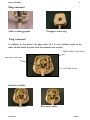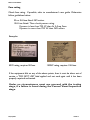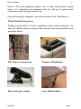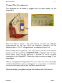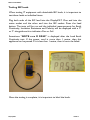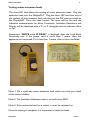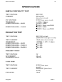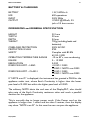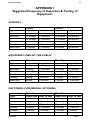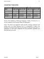
1
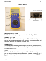
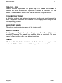
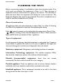
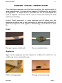
DisplayPAT Battery Powered Portable Appliance Tester With Digital Display User Manual Issue 1.1 CONTENTS SAFETY 1 GETTING STARTED FITTING BATTERIES BATTERY CHARGING INTRODUCTION 3 4 4 5 FEATURES 6 PLANNING THE TESTS Determining the Class of construction Type of equipment Type of environment Frequency of visual inspection and testing Equipment Register 8 8 9 9 9 FORMAL VISUAL INSPECTION Cable Appliance Plug external Plug internal Fuse rating 10 10 11 11 12 OPERATION Testing Class I equipment Class I Earth Connection Testing Class II equipment Testing IEC leads Testing mains extension leads Testing long extension leads Testing surge protected appliances Fuse Check Failure 13 14 15 16 17 18 18 19 SPECIFICATION 20 APPENDIX I Suggested Frequency of Inspection & Testing of Equipment 22 CARING FOR YOUR DISPLAYPAT (inside back cover) FIRST STOP SAFETY 1 SAFETY Thank you for purchasing the DisplayPAT. For safety and full understanding of the product and its benefits, please read this manual carefully before attempting to use it. 1. This manual contains all the information necessary to carry out in-service testing of all electrical appliances. If after reading this manual you are still not confident about carrying out the tests then please consider either: Attending one of our “Demystifying Portable Appliance Testing” courses held around the UK or studying our Distance Learning Package on Portable Appliance Testing. See our website www.firststopsafety.co.uk for details. 2. Before use, please check the unit for cracks or any other damage. Make sure the unit is free dust, grease and moisture. Also check any associated leads and accessories for damage. Do not use if damaged. 3. Do not touch the appliance being tested or the test probe tip when the DisplayPAT is performing a test. Where possible, use the crocodile clip provided to attach the probe to the appliance. 4. Do not use the DisplayPAT if the battery cover is not fitted. 5. The unit is powered from 6 x rechargeable 1.2V NiMH batteries with 1800 mAh or greater. Caution – please use only the specified battery type. 6. Do not connect the DisplayPAT to the mains supply via the IEC inlet. If mains voltage is inadvertently applied to the DisplayPAT via the IEC socket, an internal buzzer will sound continuously and ‘Err’ message will be displayed on the screen. This is a safety feature only. The DisplayPAT should not be used to determine if a mains socket is live. 7. A battery charger rated at 12V and 330mA is provided with the DisplayPAT. DisplayPAT ISSUE 1.1 FIRST STOP SAFETY 2 8. There are no user serviceable parts in this unit other than batteries. Under no circumstances should the user attempt to open the unit, other than the battery compartment. If opened, the warranty will be invalidated. 9. The unit may be cleaned with a soft, dry cloth. Do not use moisture, abrasives, solvents or detergents, which can be conductive. The unit should be kept in warm, dry conditions away from direct sources of heat or light. It is strongly advised not to keep the unit in a tool box where other tools may damage it. 10. The DisplayPAT is guaranteed for one year from the date of purchase. Please keep your invoice as proof of purchase. Should the unit require a service, repair or calibration, please return it to the address at the back of this user manual. 11. When returning the unit, please contact the Sales Department to receive a Returns Number. The owner will be advised of any costs prior to work commencing. DisplayPAT ISSUE 1.1 FIRST STOP SAFETY 3 GETTING STARTED Before using the DisplayPAT please check that the following items have been included in the shipment: DisplayPAT unit Mains Charger Earth test probe with crocodile clip Short IEC lead User Manual Zip carry case Equipment Register form Test Record form 100 Tested, 5 Failed and 50 Fuse labels. Check for any damage in transit. If there is any sign of damage, please report it to your supplier immediately and do not attempt to repair the unit. DisplayPAT ISSUE 1.1 FIRST STOP SAFETY 4 BATTERY CHARGING New batteries should be charged for at least 12 hours prior to use. Batteries must always be in position while the DisplayPAT is in use. When the batteries discharge to a predetermined low threshold value, the DisplayPAT will display a 'Connect charger' message. Approximately 10 further tests can be performed, after this message has first been displayed, before Auto Power Down occurs. The ‘Auto Power Down’ function will occur after 10 minutes of inactivity, or when the battery is low, to preserve battery life. The message ‘Auto Power Down’ will be displayed on the screen for 3 seconds before Auto Power Down occurs. Display results will be lost when Auto Power Down occurs. When the DisplayPAT is next powered up, it reverts to the ‘select test’ screen. The DisplayPAT will carry out a minimum of 600 tests when fully charged. In the event of discharged batteries, the DisplayPAT will operate fully from the battery charger. Do not remove the batteries. A new unit or new batteries should be charged for at least 12 hours before use with the batteries installed in the unit. To charge the batteries, plug the charger into a mains socket, then connect the charger jack to the socket on the DisplayPAT. The ~ symbol will flash on the display to show that the charger is connected and the battery symbol will flash while the unit is charging. When the battery is fully charged, the battery symbol will show continuously. Used batteries should be disposed of in accordance with local directives, and not in standard landfill waste. DisplayPAT ISSUE 1.1 FIRST STOP SAFETY 5 INTRODUCTION The Electricity at Work Regulations 1989 (EAW) places certain requirements on employers, designed to control risks that can arise from the use of electricity. In practice, this means that all electrical appliances at work need to be inspected and tested. The DisplayPAT is a compact hand-held battery powered Portable Appliance Tester, and can be used to test PCs, monitors, kettles, desk lights, drills, hairdryers etc. If an appliance has a plug it can be tested on DisplayPAT. The clear controls and displays make this instrument very easy to use. The instructions, labels and sample records supplied make it very easy for anyone to undertake safety testing on all electrical appliances. The user has only to decide whether the equipment to be tested is built to a Class I or Class II construction. The supplied test clip is connected and the appropriate button pressed. Before any PAT Testing is carried out, it is very important to inspect the appliance. Many faults, e.g. a wrong value fuse or a wrongly wired plug, can only be found by careful inspection. This user manual sets out how this can be carried out. Also included are master forms that can be used for managing PAT Testing in the workplace. These can be copied as many times as required. DisplayPAT ISSUE 1.1 FIRST STOP SAFETY 6 FEATURES RED POWER BUTTON Hold for 1 second to power up or power down the DisplayPAT. CLASS I BUTTON Selects the Class I automatic test sequence. When this button is pressed, the unit will test Earth Continuity and Insulation Resistance showing the results for each test and an overall PASS or FAIL. CLASS II TEST Selects the Class II automatic test sequence. When this button is pressed, the unit will test Insulation Resistance showing the result for the test and an overall PASS or FAIL. LEAD Selects the Lead automatic test sequence. When this button is pressed, the unit will carry out an Earth Continuity, Insulation Resistance and a Polarity test showing the results for each test and an overall PASS or FAIL. DisplayPAT ISSUE 1.1 FIRST STOP SAFETY 7 CLASS II + ON Enables contrast adjustment on power up. The LEAD or CLASS 1 buttons can then be used to adjust the contrast as indicated on the display. The CLASS II button can then be used to accept and exit. OTHER FUNCTIONS In addition, buttons are assigned temporary functions at certain points in tests. Temporary functions are indicated in the display for an image of the corresponding button. SHORT IEC LEAD This allows mains extension leads to be tested easily. SAMPLE FORMS An “Equipment Register” and an “Equipment Test Record” form is included. These can be copied and used as often as required. The user manual refers to this under the relevant sections. LABELS 100 ‘tested’ labels, 5 ‘failed’ labels and 50 fuse labels are supplied with each unit. Additional labels are available to purchase separately. DisplayPAT ISSUE 1.1 FIRST STOP SAFETY 8 PLANNING THE TESTS Before commencing testing, it is advisable to take a few minutes to plan. First of all work out whether the equipment is Class I or II. Then the type of equipment and the environment it is going to be used in. This will help to determine how often the inspection and testing has to be carried out. The Equipment Register then needs to be prepared. Once this is completed, one is ready to commence Inspection and Testing. Class of construction All equipment that uses mains electricity is either Class I or Class II. Knowing the Class of the equipment is important when planning the testing. If the symbol is present on the rating plate the equipment is Class II. If the symbol is missing, assume that the equipment is Class I. Mains extension leads and IEC leads are treated as Class 1 appliances. Type of equipment For the purpose of planning, electrical equipment is categorized into 5 types as shown below. In general, the easier it is to move an appliance, the higher the chances of damage to it and the more frequently it has to be tested. Stationary equipment: Refrigerators and washing machines are examples. Information Technology equipment: This includes computers, VDUs, data terminals, telephones, printers, fax machines and photocopiers. Movable (transportable) equipment: Items that occasionally, like fans and fires would fit in this category. are moved Portable appliance: These are appliances such as vacuum cleaners, toasters and kettles which can easily be moved whilst connected to the mains. Handheld appliance: This is equipment intended to be held in the hand during normal use like a hair dryer or drill. DisplayPAT ISSUE 1.1 FIRST STOP SAFETY 9 Environment The location of equipment will have a bearing on the frequency of testing. For example an item that is used in a low-risk environment such as an office will have a much lower risk of damage than an item used on a construction site. Please see below for various examples. Low risk: Offices, shops, hotels and nursing homes Medium risk: Schools High risk: Factories, commercial kitchens and equipment used by the public. Very high risk: Construction sites Frequency of visual inspection and testing It is not essential to carry out inspecting and testing every year. Table 1 below gives some intervals that are recommended in low risk environments, such as offices, shops, hotels, and nursing homes. (Timescales for other environments can be found in Appendix I) Type Class I Inspection Insp. & test Class II Inspection Insp. & test Stationary IT Movable Portable Hand-held 24 months 24 months 12 months 12 months 6 months 24 months 24 months 24 months 24 months 6 months 48 months 48 months 24 months 24 months 12 months none none none none none Table 1: Frequency of inspection and testing in low risk environments Equipment Register This form is used to list all the electrical equipment in the business. Information, such as Class I or II, type of equipment and frequency of test is recorded. A blank form is supplied, and this can be photocopied and used if additional sheets are required. As new equipment is purchased, this needs to be added to the register. DisplayPAT ISSUE 1.1 FIRST STOP SAFETY 10 FORMAL VISUAL INSPECTION Once the above preparation work has been carried out, the visual inspection is quite straightforward. It is important to prepare a Test Record for each piece of equipment. A sample form is provided that can be photocopied and used as required. This form will be used to record the history of visual inspection and testing. Formal Visual Inspection is a very important part of making sure that appliances are safe to use. In fact, the majority of faults can only be found by a good visual inspection of the appliance. The following is a list of faults to look for: Cable Damage to power cable sheath Any non-standard joints Appliance Signs that the equipment has been subject to conditions for which it is not suitable, e.g. wet or excessively rusty. Cable not being gripped DisplayPAT Damage to external casing ISSUE 1.1 FIRST STOP SAFETY 11 Plug external Cable not being gripped Damage to mains plug Plug internal In addition to the above, the plug cover (if it is not molded) needs to be taken off and check that the cable terminations are correct. EARTH WIRE: Green/Yellow NEUTRAL WIRE: Blue LIVE WIRE: Brown Examples of faults: Fuse not being used DisplayPAT Bare wires visible ISSUE 1.1 FIRST STOP SAFETY 12 Fuse rating Check fuse rating. If possible, refer to manufacturer's user guide. Otherwise follow guidelines below: 3A or 5A fuse fitted: NO action. 13A fuse fitted: Then check power rating. If power is less than 700 W then fit 3 Amp Fuse. If power is more than 700 W then NO action. Examples: 40W rating, requires 3A fuse. 1200W rating, requires 13A fuse. If the equipment fails on any of the above points, then it must be taken out of service, a "DO NOT USE" label applied and not used again until it has been properly repaired and tested. Under no circumstances must one proceed with the testing stage, if a failure is found during the Formal Visual Inspection stage. DisplayPAT ISSUE 1.1 FIRST STOP SAFETY 13 OPERATION Testing Class I equipment The equipment to be tested is plugged into the mains socket on the DisplayPAT. The test clip is connected to any exposed metal on the equipment. For example on a kettle this will be the element. On a PC it will be the metal case. Please ensure the appliance is switched on, if applicable. Press the Class I button. The tests will be run and the individual measurements for Earth Continuity and Insulation Resistance will be displayed with a ‘P’ or ‘F’ alongside each to indicate a Pass or Fail. When testing Class I appliances, it is important to put the on/off button/ switch to the "On" position. If SWITCH ON is displayed after the fuse check, please check that the appliance is switched on and is correctly connected to the DisplayPAT. Please also refer to notes on page 19 for more detail. Sometimes “NOTE x.xx Ω PASS” is displayed after the Class I Earth Continuity test. If the power cord is more than 1 metre, then this appliance can be passed. If it is less than 1 metre, then it has to be failed. Note 1: When the tests are performed, it is important to flex the power lead to make sure that any loose connections are stressed and are picked up by the test. The Earth Continuity test is repeated automatically to look for this. DisplayPAT ISSUE 1.1 FIRST STOP SAFETY 14 Note 2: On some appliances, paint, rust or scale will prevent a good earth. It is important to persevere and try and get a good earth connection when carrying out this test, Once the testing is complete, record the results on the Test Record. Class I Earth Connection Finding a good earth on Class I appliances comes with experience. To help you identify where to connect the test lead, we have provided a few examples below. PC: Case or connector Toaster: Metalwork Hot melt gun: nozzle Iron: Behind plate DisplayPAT ISSUE 1.1 FIRST STOP SAFETY 15 Testing Class II equipment The equipment to be tested is plugged into the mains socket on the DisplayPAT. Press the Class II button. The tests will be run and the individual measurements for the fuse check and Insulation Resistance will be displayed with a ‘P’ or ‘F’ alongside each to indicate a Pass or Fail. When testing Class II appliances, it is important to put the on/off button/ switch to the "On" position. If SWITCH ON is displayed after the fuse check, please check that the appliance is switched on and is correctly connected to the DisplayPAT. Please also refer to notes on page 19 for more detail. Where the appliance being tested has more than one area of possible insulation breakdown, such as cooling slots or cover joints, it is advisable to connect the test probe to this and then repeat the test. Once the testing is complete, record the results on the Test Record. DisplayPAT ISSUE 1.1 FIRST STOP SAFETY 16 Testing IEC leads When testing IT equipment with detachable IEC leads, it is important to test these leads as individual items. Plug both ends of the IEC lead into the DisplayPAT. One end into the mains socket and the other end into the IEC socket. Press the Lead button. The tests will be run and the individual measurements for Earth Continuity, Insulation Resistance and Polarity will be displayed with a ‘P’ or ‘F’ alongside each to indicate a Pass or Fail. Sometimes “NOTE x.xx Ω PASS” is displayed after the Lead Earth Continuity test. If the power cord is more than 1 metre, then this appliance can be passed. If it is less than 1 metre, then it has to be failed. Once the testing is complete, it is important to label the leads. DisplayPAT ISSUE 1.1 FIRST STOP SAFETY 17 Testing mains extension leads The short IEC lead allows the testing of mains extension leads. Plug the extension lead into the DisplayPAT. Plug the short IEC lead into one of the sockets of the extension lead and also into the IEC testing socket on the DisplayPAT. Press the Lead button. The tests will be run and the individual measurements for Earth Continuity, Insulation Resistance and Polarity will be displayed with a ‘P’ or ‘F’ alongside each to indicate a Pass or Fail. Sometimes “NOTE x.xx Ω PASS” is displayed after the Lead Earth Continuity test. If the power cord is more than 1 metre, then this appliance can be passed. If it is less than 1 metre, then it has to be failed. Note 1: On a multi-way mains extension lead, make sure that you check all the socket outlets. Note 2: The Insulation Resistance test is carried out at 500V. Note 3: If the extension lead has a switch, it must be switched on. Once the testing is complete, it is important to label the leads. DisplayPAT ISSUE 1.1 FIRST STOP SAFETY 18 Testing long extension leads When testing extension leads longer than 5 metres, the DisplayPAT will show FAIL for the Earth Continuity test. This is because of the additional resistance due the extra length of the lead. In this case the user can refer to the following table to see if the extension lead has a resistance that falls below the limits shown for that length. Lead length Up to 10 m Up to 15 m Up to 20 m Up to 25 m Up to 30 m Up to 35 m Up to 40 m Up to 45 m Up to 50 m PASS limit less than 0.3 ohms less than 0.4 ohms less than 0.5 ohms less than 0.6 ohms less than 0.7 ohms less than 0.8 ohms less than 0.9 ohms less than 1.0 ohms less than 1.1 ohms Note: If the Earth Continuity is a FAIL, the tester will not carry on with the Insulation Resistance and Wiring tests. Testing surge protected appliances Surge protected appliances can fail the Insulation Resistance test as this is carried out at a high voltage (500V DC) and cause the protection devices to activate. Expect to get an Insulation Resistance FAIL on an appliance that is surge protected. Note: If the Insulation Resistance is a FAIL, the tester will not carry out the Wiring test. DisplayPAT ISSUE 1.1 FIRST STOP SAFETY 19 FUSE CHECK FAILURE If the display indicates ‘SWITCH ON?’, then there are the following possible reasons for failure: The appliance’s main switch may not be set to the ‘On’ position. Rectify this and restart the test. The appliance may not be correctly connected to the DisplayPAT. Rectify this and restart the test. Ruptured fuse: Remove any fuse/s and check the fuse continuity by an alternative means. Ensure that the appliance is disconnected from any mains power whilst the fuses are being examined, then reassemble any fuse/s, reconnect the appliance to the DisplayPAT, ensure the appliance switch is set to the ‘On’ position and restart the appropriate test. Appliance Internal Circuitry: If the fuse/s are undamaged, the ‘SWITCH ON?’ display may be due to a switching device inside the appliance which only operates when the appliance is engaged at mains voltage. A ‘fail’ in such circumstances does not necessarily mean a fuse is ruptured or the appliance is faulty. When the ‘SWITCH ON?’ message is displayed, the DisplayPAT automatic testing can be allowed to continue by selecting ‘SKIP’. If it is decided that the appliance is faulty, when the ‘SWITCH ON?’ message is displayed, the test should be terminated by selecting ‘EXIT’ and unplugging the appliance from the DisplayPAT. DisplayPAT ISSUE 1.1 FIRST STOP SAFETY 20 SPECIFICATION EARTH CONTINUITY TEST TEST VOLTAGE CURRENT OC VOLTAGE TOLERANCE FIXED PASS LEVEL – LEAD FIXED PASS LEVEL – CLASS I 500 V DC 200 mA DC (into short circuit) 4V DC (into open circuit) +/- (5% + 2 digits) <0.10Ω = PASS <0.20Ω = Note x.xx PASS <0.10Ω = PASS <0.20Ω = Note x.xx PASS INSULATION TEST TEST VOLTAGE TEST CURRENT TOLERANCE FIXED PASS LEVEL – LEAD FIXED PASS LEVEL – CLASS 1 FIXED PASS LEVEL - CLASS II 500 V DC at 1mA (<600V DC into open circuit) 1.5mA (into short circuit) <100MΩ +/- (5% + 2 digits) > 1.0 MΩ > 1.0 MΩ > 2.0 MΩ POLARITY TEST TEST VOLTAGE SC CURRENT WORKING LOAD 5V 0.5 mA >30 kΩ FUSE TEST TEST VOLTAGE TEST CURRENT PASS LEVEL DisplayPAT 4V DC (into open circuit) 200mA DC (into short circuit) >2mA ISSUE 1.1 FIRST STOP SAFETY 21 BATTERY & CHARGING BATTERY LIFE INPUT OUTPUT 1.2V, NiMH x 6 600 operations 230V 50Hz 12VDC @300mA, 5.5 jack x 2.5 bore centre DIMENSIONS and GENERAL SPECIFICATION HEIGHT WIDTH DEPTH WEIGHT OVERLOAD PROTECTION PROTECTION CLASS SAFETY OPERATING TEMPERATURE RANGE RANGE RESOLUTION FIXED PASS LIMIT – LEAD FIXED PASS LIMIT – CLASS 1 210 mm 90 mm 54 mm 700g (including leads and batteries) 300V AC/DC IP20 Complies with BS EN 61010-1:2001 -10 to 40°c, non-condensing 0 – 19.99Ω 0.01Ω <0.10Ω = PASS <0.20Ω = NOTE x.xx PASS <0.10Ω = PASS <0.20Ω = NOTE x.xx PASS If “NOTE x.xx Ω” is displayed, the instrument has granted a PASS for the appliance under test, where Earth Continuity is higher than the lower pass level of 0.10Ω but within the higher pass level of 0.20Ω. The advisory NOTE alerts the end user of the DisplayPAT, who should take note of the Earth Continuity resistance value and reach a pass/fail decision for the appliance. This is normally due to longer power cords. If the Power cord on the appliance is longer than 1 metre and less than 5 metres, then the display may show “NOTE x.xx Ω”. In this case the user can pass the appliance. DisplayPAT ISSUE 1.1 FIRST STOP SAFETY 22 APPENDIX I Suggested Frequency of Inspection & Testing of Equipment SCHOOLS Type Class I Inspection Insp. & test Class II Inspection Insp. & test Stationary IT Movable Portable Hand-held 12 months 12 months 4 months 4 months 4 months 12 months 12 months 4 months 4 months 4 months 12 months 12 months 12 months 12 months 12 months 48 months 48 months 48 months 48 months 48 months EQUIPMENT USED BY THE PUBLIC Type Class I Inspection Insp. & test Class II Inspection Insp. & test Stationary IT Movable Portable Hand-held monthly monthly weekly weekly weekly 3 months 3 months 1 month 1 month 1 month 12 months 12 months 6 months 6 months 6 months 12 months 12 months 12 months 12 months 12 months FACTORIES, COMMERCIAL KITCHENS Type Class I Inspection Insp. & test Class II Inspection Insp. & test Stationary IT Movable Portable Hand-held 12 months 12 months 1 month 1 month 1 month 12 months 12 months 3 months 3 months 3 months DisplayPAT 12 months 12 months 12 months 6 months 6 months 12 months 12 months 12 months 6 months 6 months ISSUE 1.1 FIRST STOP SAFETY 23 CONSTRUCTION SITES Type Class I Inspection Insp. & test Class II Inspection Insp. & test Stationary IT Movable Portable Hand-held 1 month 1 month 1 month 1 month 1 month 1 month 1 month 1 month 1 month 1 month 3 months 3 months 3 months 3 months 3 months 3 months 3 months 3 months 3 months 3 months Source: The Institute of Electrical Engineers; Code of Practice for Inservice Inspection and Testing of Electrical Equipment. Note: The above are suggested initial periods. If during inspection testing items are always passing, then it is acceptable to reduce frequency of testing. Conversely, if many items are found to fail, then important to test more frequently till any particular problems identified and corrected. DisplayPAT and the it is are ISSUE 1.1 CARING FOR YOUR DISPLAYPAT Annual calibration Your DisplayPAT tester is an accurate instrument and it is important to make sure that it is continues to measure correctly. A faulty tester could fail to pick up any faults with electrical appliances and results in passing them. To prevent this and ensure the accuracy of your DisplayPAT, we recommend that calibration is carried out annually. We will send you an annual reminder by e-mail or letter. When you return the DisplayPAT to us we check it out thoroughly and: Calibrate it with traceability back to National Standards. Refurbish the unit and upgrade it if required. Carry out a PAT test on the tester. Issue a Calibration Certificate. Collection & Delivery Service We can arrange for the DisplayPAT to be collected for calibration and delivered back to you within 5 working days. All you have to do is to send us a completed order form. Warranty As long as your DisplayPAT is calibrated annually by First Stop Safety we provide a Lifetime Warranty. Should the DisplayPAT fail for any reason between annual calibrations please give us a call. We will repair it and ship it back to you free of charge. By calibrating your tester annually your Lifetime Warranty will cover your DisplayPAT for many years. Booking a calibration This couldn’t be easier. You can request your calibration in a number of ways. Download a booking form from our website www.firststopsafety.co.uk Send us an e-mail to [email protected] Ring us on 01904 529054 Remember: All you have to do is to send us the order. We will do everything else. Warranty Conditions First Stop Safety has complete confidence in our DisplayPAT testers enabling us to provide a Lifetime Warranty free of charge. To retain the validity of the Lifetime Warranty the unit must be returned to First Stop Safety annually for a calibration. Note: If the calibration is allowed to expire, the Lifetime Warranty is invalidated. You have a one month grace period with regards to your calibration date. This means that you have one calendar month after the calibration expiry date in which to book your tester in for calibration. The Lifetime Warranty covers the DisplayPAT unit only, not accessories. If your unit develops a fault we repair it free of charge as long as your unit’s Lifetime Warranty has been maintained. What is not covered by the Lifetime Warranty If the unit has been water damaged. For example soaked in water or submerged in water or any other fluid. If the unit has been physically damaged beyond fair wear and tear. e.g. where the unit has had mains power applied to the white testing socket or the IEC socket on the upper face of the PAT tester. Repairs if the unit has not been returned for annual calibration. Repairs to accessories. For example repairs to adaptor leads such as the 110V adaptors. The cost of the annual calibration. © 2011 First Stop Safety 11 Glaisdale Road Northminster Business Park York YO26 6QT t: 01904 791050 f: 01904 352225 e: [email protected] w: www.firststopsafety.co.uk