1
R5976560
user’s manual
R5976560
Title:
OVERVIEW-FPR67-DL User’s Manual
ID-no.: R5976560
Date:
2003-03
main issue
chapter 1
new
chapter 2
new
chapter 3
new
chapter 4
new
chapter 5
new
chapter 6
new
chapter 7
new
chapter 8
new
chapter 9
new
chapter 10
new
chapter 11
new
chapter 12
new
chapter 13
new
chapter 14
new
chapter 15
new
update
new: The corresponding chapters are new or completely revised.
corr.: Passages of the corresponding chapter were corrected; see modification bars.
add.: Passages of the corresponding chapter were added; see modification bars.
Document History
Modifications which result in a new version are indicated by a vertical bar.
Keep this sheet!
Trademarks
Brand and product names mentioned in this manual may be trademarks, registered trademarks or
copyrights of their respective holders. All brand and product names mentioned in this manual
serve as comments or examples and are not to be understood as advertising for the products or
their manufacturers.
Copyright © 2002, 2003 by Barco Control Rooms GmbH
Die Weitergabe sowie die Vervielfältigung aller Unterlagen, die von uns überlassen werden, deren
Verwertung und Mitteilung ihres Inhaltes an Dritte ist nicht gestattet, soweit dies nicht ausdrücklich zugestanden ist. Urheberrechte, insbesondere auch solche an Software, werden nur insoweit
übertragen, als es für die Erreichung des speziellen Vertragszwecks erforderlich ist. Zuwiderhandlungen können zu Schadensersatz verpflichten. Alle Rechte aus der Erteilung eines Patents
oder der Eintragung eines Gebrauchsmusters verbleiben bei uns.
Copyright © 2002, 2003 by Barco Control Rooms GmbH
All rights reserved. No part of this document may be copied, reproduced or translated. It shall not
otherwise be recorded, transmitted or stored in a retrieval system without the prior written consent
of Barco Control Rooms GmbH.
Guarantee and Compensation
Barco Control Rooms GmbH provides a guarantee relating to perfect manufacturing as part of the
legally stipulated terms of guarantee. On receipt, the purchaser must immediately inspect all delivered goods for damage incurred during transport, as well as for material and manufacturing faults.
Barco Control Rooms GmbH must be informed immediately in writing of any complaints.
The period of guarantee begins on the date of transfer of risks, in the case of special systems and
software on the date of commissioning, at the latest 30 days after the transfer of risks. In the event
of justified notice of complaint, Barco Control Rooms GmbH can repair the fault or provide a replacement at its own discretion within an appropriate period. If this measure proves to be impossible or unsuccessful, the purchaser can demand a reduction in the purchase price or cancellation of
the contract. All other claims, in particular those relating to compensation for direct or indirect
damage, and also damage attributed to the operation of software as well as to other services provided by Barco Control Rooms GmbH, being a component of the system or independent services,
will be deemed invalid provided the damage is not proven to be attributed to the absence of properties guaranteed in writing or due to the intent or gross negligence on the part of Barco Control
Rooms GmbH
If the purchaser or a third party carries out modifications or repairs on good delivered by Barco
Control Rooms GmbH, or if the goods are handled incorrectly, in particular if the systems are
commissioned or operated incorrectly or if, after the transfer of risks, the goods are subject to influences not agreed upon in the contract, all guarantee claims of the purchaser will be rendered invalid. Not included in the guarantee coverage are system failures which are attributed to programs
or special electronic circuitry provided by the purchaser, e. g. interfaces. Normal wear as well as
normal maintenance are not subject to the guarantee provided by Barco Control Rooms GmbH either.
The environmental conditions as well as the servicing and maintenance regulations specified in
this manual must be complied with by the customer.
Revision sheet
To:
Barco Control Rooms GmbH
An der Rossweid 5 • D-76229 Karlsruhe • Germany
Phone (49) (721) 6201-0 • Fax (49) (721) 6201-298
E-mail [email protected], Web www.barcocontrolrooms.de
BARCO N.V. Projection Systems
Noordlaan 5 • B-8520 Kuurne • Belgium
Phone (32) (56) 36-8211 • Fax (32) (56) 36-8251
E-mail [email protected]• Web www.barcocontrolrooms.com
From:
Date:
Please correct the following points in this documentation (R5976560)
page
wrong
correct
Contents
1 Introduction .................................................................................................................................. 1-1
1.1 How This Manual Is Organized .......................................................................................... 1-2
1.2 Styles And Symbols ............................................................................................................ 1-3
1.3 Safety Information............................................................................................................... 1-4
1.3.1 Precautions.................................................................................................................. 1-6
1.3.2 Unpacking of Devices ................................................................................................ 1-6
1.3.3 Modification of Devices ............................................................................................. 1-6
2 Abbreviated Summary ................................................................................................................. 2-1
2.1 Design.................................................................................................................................. 2-2
2.2 Properties of OVERVIEW-FPR67-DL .................................................................................. 2-3
3 Design and Function .................................................................................................................... 3-1
3.1 Components of OverView-fPR67-DL ................................................................................ 3-2
3.1.1 Projection Unit............................................................................................................ 3-2
3.1.2 Lamp Module.............................................................................................................. 3-3
3.1.3 Illumination Unit ........................................................................................................ 3-3
3.1.4 Projection Unit............................................................................................................ 3-3
3.1.5 Housing....................................................................................................................... 3-3
3.1.6 Screen Module ............................................................................................................ 3-4
4 Location and Functions of Control .............................................................................................. 4-1
4.1 Front Access ........................................................................................................................ 4-2
4.2 Control Unit......................................................................................................................... 4-3
4.2.1 Power, source and communication connections [1] ................................................... 4-3
4.3 Control Panel Terminology................................................................................................. 4-5
4.3.1 Local keypad............................................................................................................... 4-5
4.3.2 Remote control ........................................................................................................... 4-5
4.3.3 Terminology of keypad and RCU controls ................................................................ 4-7
5 Connections.................................................................................................................................. 5-1
5.1 Power connection ................................................................................................................ 5-2
5.1.1 AC Power (mains) cord connection ........................................................................... 5-2
5.1.2 Fuses ........................................................................................................................... 5-2
5.1.3 Switching on ............................................................................................................... 5-2
5.1.4 Image projection ......................................................................................................... 5-2
5.1.5 Lamp Run Time.......................................................................................................... 5-3
5.1.6 Switching to Stand-by ................................................................................................ 5-3
5.1.7 Switching Off.............................................................................................................. 5-3
5.1.8 Input Connections....................................................................................................... 5-4
5.1.9 Set up of the input selection: ...................................................................................... 5-4
5.1.10 5-cable Input Slot (slot 1) ......................................................................................... 5-5
5.1.11 Computer input/Monitor output ............................................................................... 5-6
5.1.12 Video Input ............................................................................................................... 5-6
5.1.13 S-Video Input ........................................................................................................... 5-6
5.1.14 Serial Digital Input / Serial Digital Output............................................................... 5-7
5.1.15 IEEE 1394 Input ....................................................................................................... 5-7
5.1.16 Communication Connections ................................................................................... 5-7
5.1.17 RS232 in / RS232 out ............................................................................................... 5-7
5.1.18 Communication port for communication with peripherals ...................................... 5-8
5.1.19 TRIG Output............................................................................................................. 5-8
5.1.20 MOUSE .................................................................................................................... 5-8
5.1.21 Audio Connections ................................................................................................... 5-8
6 Controlling ................................................................................................................................... 6-1
6.1 RCU used in a hardwired configuration.............................................................................. 6-2
6.2 How to use the RCU?.......................................................................................................... 6-3
6.3 Projector address ................................................................................................................. 6-4
6.3.1 Using the RCU............................................................................................................ 6-4
6.3.2 Displaying a Projector Address .................................................................................. 6-4
6.3.3 How to Program an Address into the RCU? .............................................................. 6-4
6.3.4 Picture Controls with Direct Access........................................................................... 6-4
6.3.5 Sound controls with direct access............................................................................... 6-5
7 Start Up of the Adjustment Mode................................................................................................ 7-1
7.1 Adjustment mode ................................................................................................................ 7-2
7.1.1 Password ..................................................................................................................... 7-2
8 Random Access Adjustment Mode.............................................................................................. 8-1
8.1 File Service.......................................................................................................................... 8-2
8.1.1 Load File..................................................................................................................... 8-2
8.1.2 Edit File ...................................................................................................................... 8-3
8.1.3 Rename ....................................................................................................................... 8-6
8.1.4 Copy............................................................................................................................ 8-6
8.1.5 Delete.......................................................................................................................... 8-7
8.1.6 Options........................................................................................................................ 8-7
8.2 Picture Tuning ..................................................................................................................... 8-8
8.2.1 Color Temperature...................................................................................................... 8-8
8.2.2 Gamma........................................................................................................................ 8-9
8.2.3 Color Depth ................................................................................................................ 8-9
8.2.4 Input Balance .............................................................................................................. 8-9
8.2.5 Black Color............................................................................................................... 8-10
8.3 Audio Tuning .................................................................................................................... 8-11
8.3.1 Volume, Balance, Bass and Treble........................................................................... 8-11
8.3.2 Mute.......................................................................................................................... 8-11
8.3.3 Fade........................................................................................................................... 8-11
8.3.4 Mode [stereo]/[mono]............................................................................................... 8-11
8.3.5 Video - Audio lock ................................................................................................... 8-12
8.4 Geometry ........................................................................................................................... 8-13
8.4.1 Shift........................................................................................................................... 8-13
8.4.2 Size ........................................................................................................................... 8-13
8.4.3 Blanking.................................................................................................................... 8-14
8.4.4 Aspect Ratio [5:4]/[4:3]/[16:9]................................................................................. 8-14
8.4.5 Options...................................................................................................................... 8-14
9 Installation Mode ......................................................................................................................... 9-0
9.1 Input Slots............................................................................................................................ 9-1
9.2 Configuration....................................................................................................................... 9-2
9.3 No Signal ............................................................................................................................. 9-3
9.4 Quick Access Keys.............................................................................................................. 9-4
9.5 Startup Mode ....................................................................................................................... 9-5
9.6 OSD color (On-Screen Display) ......................................................................................... 9-6
9.7 Internal Patterns................................................................................................................... 9-7
9.8 Double Lamp Mode............................................................................................................. 9-8
9.8.1 Hot standby................................................................................................................. 9-8
9.8.2 Cold standby ............................................................................................................... 9-8
9.8.3 Eco Mode.................................................................................................................... 9-9
9.8.4 Active lamp............................................................................................................... 9-10
10 Service Mode ........................................................................................................................... 10-1
10.1 Identification ................................................................................................................... 10-2
10.2 Change Password ............................................................................................................ 10-3
10.3 Change Language (not available).................................................................................... 10-4
10.4 Change Projector Address ............................................................................................... 10-5
10.5 Change Baudrate PC ....................................................................................................... 10-6
10.6 Reset Lamp Runtime ....................................................................................................... 10-7
10.7 Lamp Runtime History.................................................................................................... 10-8
10.8 BARCO logo ................................................................................................................... 10-9
10.9 Panel Adjustment .......................................................................................................... 10-10
10.10 Uniformity ................................................................................................................... 10-11
10.11 Preset Input Balance.................................................................................................... 10-12
10.12 I2C Diagnosis. ............................................................................................................. 10-13
11 Maintenance and Servicing...................................................................................................... 11-1
11.1 Replacing the Fans .......................................................................................................... 11-2
11.2 Cleaning........................................................................................................................... 11-3
11.2.1 Cleaning the Screen ................................................................................................ 11-3
11.3 Replacing......................................................................................................................... 11-4
11.3.1 Replacing the Lamp Module .................................................................................. 11-5
11.3.2 Replacing the Filter Pad ......................................................................................... 11-7
12 Technical Data ......................................................................................................................... 12-1
12.1 General Data.................................................................................................................... 12-2
12.2 Technical Data of Optical System................................................................................... 12-3
12.3 Technical Data Of Electrical System .............................................................................. 12-4
12.4 Interfaces ......................................................................................................................... 12-5
12.4.1 Slot 1: 5 cable input, 5×BNC ................................................................................. 12-5
12.4.2 Slot 2: Computer input/Monitor output.................................................................. 12-5
12.4.3 Slot 3: Video Input ................................................................................................. 12-6
12.4.4 Slot 4: S-Video Input.............................................................................................. 12-6
12.4.5 Slot 5: Serial digital Input / Serial digital Output................................................... 12-7
12.5 Parts List.......................................................................................................................... 12-8
12.5.1 Scope of Delivery of RSPSI29383 ......................................................................... 12-8
12.5.2 Consumables and Spare Parts................................................................................. 12-8
12.5.3 Optional Parts ......................................................................................................... 12-8
12.5.4 User’s Manuals ....................................................................................................... 12-8
12.6 Addresses......................................................................................................................... 12-9
13 Troubleshooting ....................................................................................................................... 13-1
13.1 Faults ............................................................................................................................... 13-2
13.2 Contact............................................................................................................................. 13-3
13.2.1 Hot Line .................................................................................................................. 13-3
14 Appendix A: Standard Source Set Up Files............................................................................. 14-1
15 Appendix B: Source Numbers 81 - 86 And 91 - 96................................................................. 15-1
15.1 Projector without any 800 peripheral connected............................................................. 15-2
15.2 Projector with a 800 peripheral connected...................................................................... 15-3
15.2.1 Source numbers 91 - 99. ......................................................................................... 15-3
15.2.2 Source numbers 81 - 86 .......................................................................................... 15-3
1 Intro duction
This manual describes design, function, operation and maintenance of the rear projection system
OverView-fPR67-DL.
OverView-fPR67-DL is a modular structure, built for front access, which houses a 3-panel polySilicon LCD projection engine. The LCDs have a resolution of 1280x1028 pixels (SXGA) with an
aspect ratio of 5:4. The screen has a diagonal of 67". To ensure a 100% availability, the projection
engine is designed as dual lamp system.
These features together explain the "addon" of the name OverView:
Character
meaning
F
front access
P
poly-Silicon
R
stands for SXGA
67
screen diagonal in inch
DL
dual lamp system
For better reading, the mnemonic extensions of the name will be omitted in the following chapters of this manual. Whenever the projection system is referred to, it will
be by means of the "family name" OverView.
OverView-fPR67-DL has analog interfaces and allows you to display a wide variety of common
video and RGB sources. The display can be controlled via an IR remote control or via an integrated keypad.
OverView-fPR67-DL can be lined up without any dividing parts to achieve an impressive panoramic view.
OVERVIEW-FPR67-DL (2003-03) R5976560
1-1
1.1 How Th is Manual Is Organized
This manual is divided into fifteen chapters:
Preliminary Remarks
explains the structure of the manual itself and the used typographic styles and symbols. Safety
information is provided concerning the operation of systems from BARCO.
Summary
provides a summary of the system components and characteristics.
Design and Functions
provides a technical description of the equipment listing the fundamental characteristics and
functional principles. Knowledge of this section is not absolutely essential for operation.
Location and Functions of Control
describes the functions and explains the control panel terminology
Connections
describes the interfaces of OverView fPR67-DL
Controlling
explains how OverView fPR67-DL is operated via the Remote Control Unit and the local keypad
Start Up of the Adjustment Mode
explains how to use the menu controlled software of OverView fPR67-DL
Random Access Adjustment Mode
provides an overview of the commands of OverView fPR67-DL
Installation Mode
describes the possible configurations of OverView fPR67-DL
Service Mode
explains the commands which are available in Service Mode
Maintenance and Servicing
explains how the equipment can be serviced
Technical Data
provides tabular overviews about the technical details of OverView fPR67-DL.
Troubleshooting
lists possible errors together with steps to eliminate the respective fault.
Appendix A: Standard Source Set Up Files
lists all the available set up files for the various timings
Appendix B: Source Numbers 81-85 AND 91-96
explains the relationship between source input, source number and set up file
Chapters, pages, figures and tables are numbered separately. Chapters are indicated by a »point
syntax«, e. g. 4.2.3, pages by a »dash syntax«, e. g. 2-1.
OVERVIEW-FPR67-DL (2003-03) R5976560
1-2
1.2 Styles And Symbols
The typographic styles and the symbols used in this document have the following meaning:
Helvetica bold
Labels, menus and buttons are printed in the Helvetica bold font.
Condensed
Links to both other chapters of this manual and to sites in the Internet are printed condensed. In the
on-line version of this manual all hyperlinks appear teal.
Courier
Names of files and parts from programs are printed in the Courier font.
Courier bold
Inputs you are supposed to do from the keyboard are printed in Courier bold font.
This arrow marks tips and notes.
If you do not heed instructions indicated by this symbol there is a risk of damage to
the equipment!
If you do not heed instructions indicated by this symbol there is a risk of electrical
shock and danger to personal health!
OVERVIEW-FPR67-DL (2003-03) R5976560
1-3
1.3 Safety Information
This section describes safety precautions which must be observed when installing a product from
BARCO.
Safetey
OVERVIEW-FPR67-DL is built in accordance with the requirements of the international safety
standard IEC950, UL1950 and CSA C22.2 No. 950, which are the safety standards of information
technology equipment including electrical business equipment.
The safety standards of information technology equipment impose important requirements on the
use of safety critical components, materials and isolation, in order to protect the user or operator
against the risk of electric shock and energy hazard, and having access to live parts.
Safety standards also impose limits to the internal and external temperature rises, radiation levels,
mechanical stability and strength, enclosure construction and protection against risk of fire.
Simulated single fault condition testing ensures the safety of the equipment to the use even when
the equipment’s normal operation fails.
General safety instructions
All the safety and operating instructions should be read before using this unit.
The operating instructions manual should be retained for future reference.
All warnings on the device and in the documentation manuals should be adhered to.
All instructions for operating and use of this equipment must be followed precisely.
Installation and Service
Installation and preliminary adjustments should be performed by qualified BARCO personnel or
authorized BARCO service dealers.
On Safety
Check the power rating on your outlet before connecting the devices to the wall
outlet or to a power strip. Contact your facilities manager or a qualified electrician if
you are not sure what type of power is supplied to your building.
The devices are designed to operate with single-phase power systems having a
grounded neutral conductor. To reduce the risk of electrical shock, do not plug into
any other type of power system.
A. Mains lead (AC Power cord) with CEE 7 plug:
The colors of the mains lead are colored in accordance with the following code:
Green-and-yellow:
Earth (safety earth)
Blue:
Neutral
Brown:
Line (live)
OVERVIEW-FPR67-DL (2003-03) R5976560
1-4
B. Power cord with ANSI 73.11 plug:
The wires of the power cord are colored in accordance with the following code:
Green/yellow:
Ground
White:
Neutral
Black:
Line (live)
Do not allow anything to rest on the power cord. Do not locate this product where persons will
walk on the cord.
To disconnect the cord, pull it out by the plug. Never pull the cord itself.
If an extension cord is used with this product, make sure that the total of the ampere ratings on
the products plugged into the extension cord does not exceed the extension cord ampere rating.
Also make sure that the total of all products plugged into the wall outlet does not exceed 15
amperes.
Never push objects of any kind into this product through cabinet slots as they may touch dangerous voltage points or short out parts that could result in a risk of fire or electrical shock.
Never spill liquid of any kind on the product. Should any liquid or solid object fall into the
cabinet, unplug the set and have it checked by qualified service personnel before resuming operations.
Warning: Do Not Place Flammable or Combustible Materials Near Projector!
BARCO products are designed and manufactured to meet the most stringent safety regulations.
Exposing flammable or combustible materials into close proximity of this device could result in
the spontaneous ignition of that material, resulting in a fire. For this reason, it is absolutely necessary to leave an "exclusion zone" around all external surfaces of the projector whereby no flammable or combustible materials are present. The exclusion zone must be not less than 10 cm (4").
Do not cover the projector with any material while the projector is in operation.
Keep flammable and combustible materials away from the projector at all times. Mount the projector in a well ventilated area away from sources of ignition and out of direct sun light. Never expose this product to rain or excessive moisture. In the event of fire, use sand, CO2, or dry powder
fire extinguishers; never use water on an electrical fire.
Always have service performed on this product by authorized BARCO service personnel. Always
insist on genuine BARCO replacement parts. Never use non-BARCO replacement parts as they
may degrade the safety of this device.
Use only the power cord supplied with your device. While appearing to be similar, other power
cords have not been safety tested at the factory and may not be used to power the projector. For a
replacement power cord, contact your dealer.
Slots and openings in the cabinet and the sides are provided for ventilation; to ensure reliable operation of the device and to protect it from overheating, these openings must not be blocked or
covered. This product should never be placed near or over a radiator or heat register. This product
should not be placed in a built-in installation or enclosure unless proper ventilation is provided.
OVERVIEW-FPR67-DL (2003-03) R5976560
1-5
On Servicing
Do not attempt to service this device yourself, as opening or removing covers may expose you to
dangerous voltage potential and risk of electric shock! Refer all projector service to a qualified
BARCO service center.
Adjust only those controls that are covered by the operating instructions since improper adjustment of the other controls may result in damage and will often require extensive work by a qualified technician to restore the product to normal operation.
Call for service in the following conditions :
When the power cord or plug is damaged or frayed.
If liquid has been spilled into the device.
If the product has been exposed to rain or water.
If the product does not operate normally when the operating instructions are followed.
If the product has been dropped or the cabinet has been damaged;
If the product exhibits a distinct change in performance, indicating a need for service.
When replacement parts are required, be sure the service technician has used original BARCO replacement parts or authorized replacement parts which have the same characteristics as the
BARCO original part. Unauthorized substitutions may result in degraded performance and reliability, fire, electric shock or other hazards. Unauthorized substitutions may void warranty.
Upon completion of any service or repairs to this unit, ask the service technician to perform safety
checks to determine that the unit is in proper operating condition.
1.3.1 Precaut ions
For your own protection, observe the following safety precautions when installing your device!
Observe all warnings and instructions printed on the devices!
Check that the voltage and frequency of your power supply match those printed on the device
label with the rated electrical values!
Servicing not explicitly mentioned in this manual should never be carried out by unauthorized
personnel!
1.3.2 Unpack ing of Devices
Note advises on the packaging for unpacking!
1.3.3 Modific ation of Devices
Mechanical or electrical modifications others than described in this manual must not be made to
the devices. BARCO is not liable for damages resulting from modified devices.
Only authorized personnel should carry out other maintenance work not explicitly
mentioned in this user's manual!
Never open the case of the power supply or of the projection unit without first disconnecting the power supply cord! Measurements and tests with an opened device
may be carried out only in the factory or by specially trained personnel, due to the
dangers of electrical shock.
OVERVIEW-FPR67-DL (2003-03) R5976560
1-6
2 Abbr eviated Summary
This chapter provides a summary of the system components and characteristics.
2.1 Design
High-quality and large-area displaying of monitor contents is becoming increasingly important in
conference and presentation theaters, at exhibitions, in public areas of insurance companies, banks,
hotels or transport services. Personal computers are primarily used in this context, but also UNIX
workstations. Simple data presentations are being increasingly supplemented by multimedia applications with video displays. OverView provides optimum solutions which also satisfy the highest
demands. OverView is multimedia-compatible since it can be connected to any current source
(digital and analog camcorder sources, analog video tape sources, DVD, Laserdisc, digital video
tape sources, computer data sources). Audio reproduction is possible by connecting amplifiers or
active boxes to the audio socket. Personal computers with the following graphics adapters can be
connected as the data sources: SXGA, XGA, SVGA, VGA. Workstations, Apple Macintosh and
Power Macintosh are also supported. Remote real-time switching is possible between all sources.
OverView can be used as one large monitor with a screen diagonal of 67 inches - or, due to its sophisticated layout and engineering, two or more units can be lined up to achieve an impressive
panoramic view. OverView is designed for long term operation in control rooms and each application can benefit from the high reliability and ease of use.
OVERVIEW-FPR67-DL (2003-03) R5976560
2-2
2.2 Proper ties of OVERVIEW-FPR67-DL
OverView can be used as one large monitor with a screen diagonal of 67 inches. The technologies
used guarantee the best optical properties for high-quality presentation of both computer data and
video displays:
High, Constant Reading Accuracy Over the Complete Display Panel
Optimally adjusted high-performance lens systems guarantee a distortion-free and sharp image.
Bright Displays
A 100W UHP™ lamp provides a high luminous flux which is passed on at great efficiency by
the illumination system.
High Contrast
The screen has a surface which absorbs ambient light falling on it and increases the contrast.
Dual Lamp System
The projection engines has a dual lamp system and can be operated in three operation modes:
hot standby, cold standby, eco mode.
In Hot standby both lamps are on. In case of a lamp failure, the light output of the other lamp is
immediately switched to illuminate the optics, and there is no noticeable effect on the displayed information: no loss of information, no impact on quality. Switching time is about half a
second.
In Cold standby mode the second lamp is only switched on in case a failure occurs with the
active lamp. Since the second lamp needs some minutes to reach a stable operating temperature, at the beginning the display will have reduced brightness. The contents of information,
however, is available nearly without interrupt.
Eco mode is a special version of the cold standby mode: the lamps are active in turns: every
500 hours the light path is illuminated by the other lamp. Since the lamp is switched on some
minutes in advance, the takeover of the other lamp is nearly not noticeable
Easy Adjustment and Low-maintenance
Readjustment of the components is not required. The operation time of the lamps is very high
at 8000 hours. Lamp and filters can be replaced without special training from the front.
Ready for any application
The source is automatically recognized. The projector has intelligent and user-adjustable priority switching.
OVERVIEW-FPR67-DL (2003-03) R5976560
2-3
3 Desig n and Function
This chapter provides a technical description of the equipment listing the fundamental characteristics and functional principles. Knowledge of this section is not absolutely essential for operation.
3.1 Compo nents of OverView-fPR67-DL
The OverView-fPR67-DL consists of the following components:
Structure: the structure consists of aluminum profiles. This design ensures great flexibility with
respect to the height and allows to combine multiple units in a linear or curved setup to achieve
a panoramic view.
Sheet metals to close the structure and to eliminate light and dust
Design trim (optional) for stand-alone or built-in solutions
Projection unit: The light of a UHP lamp is directed on the 3-panel LCD cube which generates
the display to be projected onto the screen via a lens. A dual lamp system ensures 100% availability of the Display Wall.
Deflection mirror: a mirror in the top part of the structure deflects the light onto the rear of the
projection screen.
Screen: The screen is selected upon the overall environmental conditions and requirements of
the field of application. The display is generated on the screen which comprises several optical
elements.
Fan: a dual lamp system also requires a dual fan system which ensures that the unit is sufficiently cooled.
3.1.1 Projecti on Unit
The projection unit incorporated in OverView has been designed for front access of interfaces and
exchange of consumables (lamp module, filters).
Figure 1
1
Dual lamp system
2
illumination unit
3
projection unit
4
deflection mirror
5
screen module
OVERVIEW-FPR67-DL (2003-03) R5976560
3-2
3.1.2 Lamp M odule
The lamp module generates the light for the subsequent projection. The lamp (100 Watt UHP (Ultra High Performance) lamp) is connected to a controller with a high switching frequency. The
emitted luminous flux is then very constant (DC light). In case of a lamp failure of the active lamp,
the second lamp is immediately switched into the light path to take over the illumination of the
optics.
The active lamp can manually be selected.
3.1.3 Illumina tion Unit
The illumination unit consists of the lens system for uniform illumination of the LCDs and the
electronics for lamp power supply and monitoring.
Optical Integrator
An optical integrator consisting out of two multi-segment lenses guarantees a uniform illumination of the LCDs and thus of the screen.
3.1.4 Projecti on Unit
The light from the lamp is split with dichroic mirrors into red, green and blue light to illuminate
three LCD panels, each of which contains the respective color-information for the red, green and
blue parts of the projected image. The LCD panels are attached to a cubical prism called X Cube
which recombines the three light paths, so the image is projected using a single lens.
Lens
X Cube
Mirror
LCDs
Lamp
Integrator
Figure 2
Poly-Silicon TFT-LCD
The LCD panels are based on Poly-Silicon technology. Poly-Silicon material consists of numerous small crystals leading to small circuitry. The results are a big aperture (ratio of a pixel’s
shutter area to it’s total area), high speed and reliability. The panels have 1,310,720 (SXGA
1280×1024) pixels.
Lens System
The projection lens system is positioned behind the X Cube. It projects the image resulting on
the LCD’s via the deflection mirror onto the rear of the screen module.
3.1.5 Housing
The housing consists of aluminum profiles covered with sheet metal. It prevents ambient light
from falling onto the rear of the screen and thus reducing the contrast. It contains the power unit,
the illumination unit, the projection unit, the control unit and the fan.
Deflection Mirror
Due to folding up the optical path by a mirror the entire depth of the pedestal device is only
822 millimeters.
OVERVIEW-FPR67-DL (2003-03) R5976560
3-3
3.1.6 Screen Module
The image is generated in the screen module. The screen is a high-precision optical component for
a high contrast image. It is a 2-element screen and consists of a Fresnel Lens and a Front element.
The screen offers viewability unter all lighting conditions, has low reflections and eliminates glare.
It displays bright sharp images at all angles including improved viewability in vertical direction.
Fresnel Lens
The Fresnel lens deflects the light coming from the projection lens system such that it falls
perpendicularly onto the lenticular screen.
Front Element
The front element screen guarantees that the light is distributed horizontally and vertically,
while maintaining a high contrast.
Texture of Surface
The surface of the screen has a special texture. This texture minimizes the direct reflection of
the light of the surrounding and contributes also to the high contrast of the screen.
OVERVIEW-FPR67-DL (2003-03) R5976560
3-4
4 Loca tion and Functions of Control
This chapter provides an overview about the controls of OverView-fPR67-DL.
4.1 Front A ccess
OverView-fPR67-DL had been designed for front access. The cover is fixed by means of two
knurled screws. Unscrew these screws to remove the cover an to get access to the consumables
(filters, lamps),and the control unit.
Figure 3
OverView-fPR67-DL, front cover removed
1
key pad
2
filter for lamp cooling
3
filter for LCD cooling
4
lamp bottom
4
lamp top
4
control unit
OVERVIEW-FPR67-DL (2003-03) R5976560
4-2
4.2 Contro l Unit
4.2.1 Power, source and communication connections [1]
1
Power switch
1 = on, 0 = off
2
Power input
autoranging from 100VAC to 240VAC
3
Video input
1 cinch or 1 BNC connector, no loop through
4
S-Video
4-pin mini-DIN
5
SDI and SDO
2× BNC terminals, serial digital input and loop through
output
6
IEE 13994
not yet implemented
7
TRIG
(mini-jack) output voltage of 5V when projector is on
8
Mouse
(DIN 13) mouse output to be connected to the mouse
input of a computer. The computer can now be controlled via the Executive Remote Control Unit
9
RS232 IN
(D9), to allow communication with external computer,
e. g. IBM PC or compatible, MAC ..
10
RS232 OUT
(D9), used to connect to next projector, RS232 IN plug
11
Communication port
(D9), allows communication with the 800 peripherals
12
IR-Acknowledged
IR-Signals are recognized
IR-Received
IR-Signals are received but not recognized by the projector
13
Projector mode indication
indicates the status of the projector
Light off:
power switch is not pressed
Red light:
power switch is pressed, projector in
standby mode
Green light: projector in operational mode
14
Diagnostics code
a)
b)
15
Remote
(mini-jack), remote input for wired remote control
OVERVIEW-FPR67-DL (2003-03) R5976560
source number
error code: a two digit error code is displayed
4-3
16
IR-receiver
17
Audio output
18
Audio input
3 audio inputs. Each audio input can be associated with
arbitrary input
19
Monitor output
the monitor of your computer can be connected to this
output if your computer is connected to the computer
input
20
Computer input
21
5-cable input
OVERVIEW-FPR67-DL (2003-03) R5976560
Receiver for control signals transmitted from the RCU
can be software switched between Video, S-Video,
RGB analog or Component Video
4-4
4.3 Contro l Panel Terminology
The projector can be controlled by the local keypad or by the remote control unit (RCU)
4.3.1 Local k eypad
The local keypad [1] is located on the front of the projector
(explanation see table 4.1)
6
16
9
0
7
8
5
6
TEXT
3
4
SHARPN
TINT
BRIGHTN
1
2
PHASE
COLOR
CONTRAST
STANDBY
EXIT
17
15
ENTER
5
PAUSE
14
11
12
9
Figure 4
The local keypad
4.3.2 Remote control
This remote control unit (RCU) includes a battery powered infrared (IR) transmitter that allows the
user to control the projector remotely.
Figure 5
IR Remote Control Unit (RCU)
OVERVIEW-FPR67-DL (2003-03) R5976560
4-5
This remote control is used for source selection, control, adaptation and set up. It includes automatic storing of the picture controls (brightness, sharpness ...) and the settings.
Other functions of the remote control are:
switching between standby and operational mode
switching to "pause" (blank picture, full power for immediate restarting)
direct access to all connected sources.
OVERVIEW-FPR67-DL (2003-03) R5976560
4-6
4.3.3 Termino logy of keypad and RCU controls
1
Function keys
have no function for this projector
2
ADJ
ADJUST key, to enter or exit the adjustment mode.
3
Address key
(recessed key), to enter the address of the projector (between 0 and
9). Press the recessed address key with a pencil, followed by pressing one digit button between 0 and 9.
4
Selection key
to direct access the zoom/focus/shift functions.
5
PAUSE
to stop projection for a short time, press 'PAUSE'. The image disappears but full power is retained for immediate restarting.
6
Standby
stand by button, to start projector when the power switch is switched
on and to switch off the projector without switching off the power
switch.
Attention : Switching to Stand-by.
When the projector is running and you want to go to stand-by, press
the stand-by key for 2 seconds until the message 'Saving data, please
wait' is displayed. Do not press any longer on the stand-by key
otherwise the projector will restart.
7
Mute
to interrupt the sound reproduction.
8
Help
on line help information (not yet available)
9
Digit buttons
direct input selection.
10
Audio controls
use these buttons to obtain the desired sound level
11
Picture controls
use these buttons to obtain the desired picture analog level
12
PHASE
used to remove the instability of the image.
13
Freeze
press to freeze the projected image.
14
TEXT
when adjusting one of the image, e.g. controls during a meeting, the
displayed bar scale can be removed by pressing 'TEXT' key first. To
re-display the bar scale on the screen, press 'TEXT' key again.
15
ENTER
to start up the adjustment mode or to confirm an adjustment or selection in the adjustment mode.
16
Cursor Keys (on
RCU) or '' and '-'
keys (cursor
keys) on the local
to make menu selections when in the adjustment mode or to
zoom/focus when the direct access is active.
keypad
Comparison between the cursor keys and the use of the '+' and '-'
keys on the local keypad
RCU
local keypad
cursor key up
cursor key down
cursor key right
cursor key left
'+' key up
'-' key down
'+' key right
'-' key left
Use the '+' and '-' keys (cursor keys) to increase or decrease the analog level of the image controls when they are first selected.
17
EXIT
to leave the adjustment mode or to scroll upwards when in the adjustment mode.
18
RC operating
indication
lights up when a button on the remote control is pressed. (This is a
visual indicator to check the operation of the remote control)
OVERVIEW-FPR67-DL (2003-03) R5976560
4-7
5 Conn ections
This chapter explains the various interfaces of OverView-fPR67-DL.
OVERVIEW-FPR67-DL (2003-03) R5976560
5-1
5.1 Power connection
5.1.1 AC Pow er (mains) cord connection
I
0
2
1
RC
VIDEO
R
3 S-VIDEO 4
G
B
H/C
SDI
SDO
V
1
5 IEE 1394
COMPUTER
6
2
TRIG
MOUSE
MONITOR
RS 232 IN
AUDIO IN
RS 232 OUT
A
AUDIO IN
B
Comm. Port
AUDIO IN
C
AUDIO OUT
Use the supplied power cord to connect your projector to the wall outlet.
Plug the female power connector into the male connector [1] at the control panel.
The power input is auto-ranging from 90 to 240 VAC.
5.1.2 Fuses
For continued protection against fire hazard:
- refer replacement to qualified service personnel
- ask to replace with the same type of fuse.
Fuse type : 5x20 T5AH/250V
5.1.3 Switchi ng on
Use the power switch [2] to switch on. When '0' is visible, the projector is switched off. When '1'
is visible, the projector is switched on.
When switching on with the power switch, the projector starts in the standby mode. The projector
mode indication lamp is red.
5.1.4 Image p rojection
To start image projection:
press the 'Stand by' button once on the local keypad or on the remote control. The projector
mode indication lamp will be green.
press a digit button to select an input source. The projector mode indication lamp will be
green.
OVERVIEW-FPR67-DL (2003-03) R5976560
5-2
5.1.5 Lamp R un Time
The operation time of the lamp is 8000 hours. The total hours of operations are counted and can be
displayed on the screen.
The total lifetime of the lamp for a safe operation at high and constant brightness is
about 8000 hours. Always replace with a same type of lamp
5.1.6 Switchi ng to Stand-by
When the projector is running and you want to go to stand-by:
Press the STANDBY key for 2 seconds until the message 'Saving data, please wait' is displayed.
Do not press any longer on the standby key otherwise the projector will restart.
5.1.7 Switchi ng Off
To switch off:
Press the STANDBY key for 2 seconds. When the message 'Saving data, please wait' is displayed, do not press any longer on the standby key otherwise the projector will restart.
Let cool down the projector at least 10 min.
Remove the paneling to gain access to the power switch.
Switch off the projector with the power switch.
When switching to standby, it is possible to restart within the first 5sec. When not
restarted within these first 5 sec., you have to wait one minute for being able to restart again. During the period when restarting is disabled, the LED display will show
a jumping square with a dash. When restarting is enabled again, two dashes will be
displayed to indicate that the projector can be restarted.
OVERVIEW-FPR67-DL (2003-03) R5976560
5-3
5.1.8 Input C onnections
OverView-fPR67-DL has multiple input connections for all common RGB and video sources. The
input can be selected either manually or automatically. When 'automatic' is selected in the Input
slots menu, by starting up the projector, it searches for an input source by scanning the inputs one
by one. If only one source is found, this source will be projected. If different sources are found, the
priority is as follows
input facilities
priority of automatic input selection
Video
1
S-Video
2
5-cable input
3
Computer
4
Serial digital input
never automatically selected
IEEE 1394 (not yet active)
never automatically selected
When a RCVDS is connected to the projector, the 'Automatic' selection is disabled.
5.1.9 Set up o f the input selection:
Press ENTER to start up the adjustment mode.
Press the cursor key up or down to select 'Installation'.
Press ENTER to display the Installation menu.
Press the cursor key up or down to select 'Input Slots'.
Press ENTER to display the Input slots menu.
In the Input slots menu the available input sources are marked with x
Press the cursor key up or down to select 'Input Slots'.
Press ENTER to toggle between [Manual] or [Automatic].
Press EXIT several times to leave the adjustment mode.
Use of a RCVDS05 or VS05 :
When using a RCVDS05, it is recommended to use a 5-cable output module in the
RCVDS. The outputs of this module have to be connected to the 5 cable input
(slot 1) of the projector.
To switch the projector in the 5-cable mode see chapter 9 Installation Mode.
OVERVIEW-FPR67-DL (2003-03) R5976560
5-4
5.1.10 5-cable Input Slot (slot 1)
Slot 1 has 5 BNC input terminals.
The following signals can be connected to these BNC connectors:
Connector name
R
G
B
H
V
RGBHV
R
G
B
H
V
RGBS
R
G
B
S
-
RGsB
R
Gs
B
-
-
Composite Video
-
Video
-
-
-
Super Video
-
Y
-
-
C
Component Video - SS
R-Y
Y
B-Y
S
-
Component Video - SOY
R-Y
Ys
B-Y
-
-
Input signal
Slot 1 selection
To select slot 1:
Press the digit button 1 on the RCU or the local keypad.
Configuration of the 5-cable input
The configuration has to be done on the 'Input slot' menu.
To change the signal format:
Press ADJUST or ENTER to start up the Adjustment mode.
Push the cursor key up or down to select Installation
Press ENTER.
Press the cursor key up or down to select 'Input Slots'
Press ENTER. The internal system will scan the inputs and displays the result in the 'Input
Slots' menu.
Push the cursor key up or down to select the first slot.
Press ENTER key to toggle the input signal priority.
Possible indication:
RGB [HS&VS]
RGB analog signals, separate sync is horizontal and vertical
sync.
RGB CS
RGB analog signals, separate sync is composite sync.
RGB CV
RGB analog signals, separate sync is composite video or trilevel sync.
RGB-SOG
RGB analog signals, sync on green is composite sync.
COMPONENT VIDEO - CS
separate sync is composite sync.
COMPONENT VIDEO
component video with composite sync on Y or composite trilevel sync on Y.
VIDEO
S-VIDEO
OVERVIEW-FPR67-DL (2003-03) R5976560
5-5
When using an RCVDS 05 with a 5 cable output module, connect these 5 cables
to this 5-cable input slot (slot1) of the projector.
All sources of the RCVDS can now be accepted by the projector.
5.1.11 Compu ter input/Monitor output
Connect the output of the graphical card of the computer to the computer input of the projector
(connection < 60 cm) or insert an interface between the output of the computer and the input of
the projector.
Connect the monitor of the computer to the monitor output of the projector.
This monitor output is only available when the computer input is used as input.
Pin configuration of the D15 connector:
1
RED
2
GREEN
3
BLUE
4
loop through to monitor
5
ground
6
ground
7
ground
8
ground
Slot 2 selection:
Press the digit button 2 on the RCU or the local keypad.
5.1.12 Video In put
Input signal:
Composite video signals from a VCR, OFF air signal decoder, etc...
1 x BNC or cinch 1.0Vpp ± 3 dB
No loop through.
Slot 3 selection:
Press the digit button 3 on the RCU or the local keypad.
5.1.13 S-Video Input
Input signal:
Separate Y-luma/C-chroma signals for higher quality playback of Super VHS-signals.
Pin configuration mini DIN plug:
1
ground luminance
2
ground chrominance
3
luminance 1.0Vpp ± 3 dB
4
chrominance 282 mVpp ± 3 dB
OVERVIEW-FPR67-DL (2003-03) R5976560
5-6
Slot 4 selection:
Press the digit button 4 on the RCU or the local keypad.
5.1.14 Serial D igital Input / Serial Digital Output
Full compatibility with digital Betacam, or digital video sources.
This avoids the need for analog processing anywhere in the video production chain and guarantees
the ultimate image quality.
An active loop through of the SDI input signal is provided for monitoring or for double or triple
stacking applications.
connections:
1 x BNC input and 1 x BNC output.
The input is always 75 Ω terminated. The output impedance of the SDO is 75 Ω.
Slot 5 selection:
Press the digit button 5 on the RCU or the local keypad.
When a RCVDS05 is connected to the projector, the SDI input is available by keying in 85 on the RCU.
5.1.15 IEEE 13 94 Input
Input not yet implemented.
5.1.16 Commu nication Connections
The following communication connections are available:
RS232 in / RS232 out.
Comm port for communication with peripheral (switchable between PPM and RC5)
RC for remote cable connection with the RCU.
MOUSE to control a PC with the projector remote control.
TRIG: output voltage to control another device.
5.1.17 RS232 i n / RS232 out
To connect a Computer, e.g. IBM PC (or compatible), Apple Macintosh to the RS 232 input of the
projector to allow communicate between the computer and the projector.
Applications:
remote control
easy adjustment of projector via IBM PC (or compatible) or MAC connection
allow storage of multiple projector configurations and set ups.
wide range of control possibilities.
address range from 0 to 255.
data communications
sending data to the projector or copying the data from the projector to a
hard memory device (hard disc, floppy, etc.).
Set up of the Baud Rate for Communication with a Computer:
see “change Baudrate PC” in chapter 10 Service Mode.
OVERVIEW-FPR67-DL (2003-03) R5976560
5-7
5.1.18 Commu nication port for communication with peripherals
This port can be configured to accept PPM or RC5 coded signals.
To change the port configuration see “800 Peripherals” in chapter 9 Installation Mode.
Connecting a RCVDS 05 to the projector:
Up to 20 inputs with the RCVDS 05 and 90 inputs when RCVDS's are linked via the expansion
module.
Serial communication with the projector.
Remote control buttons on the RCVDS to control the projector (source selection and analog
settings).
The selected source number will be displayed on a 2 digit display and the selected input module will be indicated with a LED on the rear.
For more information about the use of the RCVDS 05, consult the owner's manual of the
RCVDS05, see 12.5.4 User’s Manuals.
Connecting a VS05 to the projector:
The VS05 (see 12.5.3 Optional Parts can switch up to 5 Composite Video sources, 3 Super Video
sources and 1 RGB analog or component video source to the projector. In addition, the audio signal proper to the source, can be switched to an audio amplifier or the audio input of the projector.
For more information about the use of the VS05, consult the VS05 owner's manual, see 12.5.4
User’s Manuals.
5.1.19 TRIG O utput
5 V output voltage to trigger an external device (max. 10mA).
This voltage is available when the projector is on.
5.1.20 MOUSE
Mouse output to be connected to the mouse input of a computer. With the Executive Remote
Control (see 12.5.3 Optional Parts), the computer can now be controlled via the projector. All normal
mouse functions except the 'drag and drop' function are available. For more information about the
mouse functions, consult the owner's manual of the Executive Remote Control.
5.1.21 Audio C onnections
Three audio inputs and one audio output are available. Each audio input can be associated with an
input source using the control software of the projector, e.g. source 1 can be locked with audio input B.
Locking an audio input to a source input :
Press ENTER to start up the adjustment mode.
Press the cursor key up or down to select 'Random Access'.
Press ENTER to display the Random Access menu.
Press the cursor key up or down to select 'Audio Tuning'.
Press ENTER to display the Audio Tuning menu.
Press the cursor key up or down to select 'Video-Audio lock'.
Press the cursor key up or down to select the desired source input.
Press ENTER to toggle between [A], [B] or [C].
Press several times EXIT or ADJUST to return to the operational mode.
See also chapter 8.3.5 Video - Audio lock
OVERVIEW-FPR67-DL (2003-03) R5976560
5-8
6 Cont rolling
The projector can be controlled with
the RCU
the hardwired RCU (cable is not included)
the local keypad
Controlling the projector with the RCU and the hardwired RCU is equal.
OVERVIEW-FPR67-DL (2003-03) R5976560
6-1
6.1 RCU us ed in a hardwired configuration
Connections:
Plug one end of the remote cable in the connector on the bottom of the RCU
Plug the second side in the connector in the front panel of the projector labelled 'RC'.
OVERVIEW-FPR67-DL (2003-03) R5976560
6-2
6.2 How to use the RCU?
Point the front of the RCU directly at the screen.
When using the wireless remote control, make sure you are within the effective operating distance (30m, 100ft in a straight line). The remote control unit will not
function properly if strong light strikes the sensor window or if there are obstacles
between the remote control unit and the IR sensor.
OVERVIEW-FPR67-DL (2003-03) R5976560
6-3
6.3 Projecto r address
The projector's address may be set to any value between 0 and 255 (see 'Change projector address'
in chapter 'Service mode). When the address is set, the projector can be controlled now by the RCU
for addresses between 0 and 9.
The projector can also be controlled by computer, e.g. IBM PC (or compatible), Apple MAC, etc.
for addresses between 0 and 255.
A projector will respond to a RCU set to an address of '0' regardless of what address
is set in the projector itself.
6.3.1 Using th e RCU
The RCU is default programmed with address 0, 'zero address'. With that 'zero address' programmed into the RCU, every projector, without exception will listen to the commands given by
this RCU. If it is necessary to control a specific projector, than enter the projector address into the
RCU (only when that address is between 0 and 9). The projector with the corresponding address
will listen to that specific RCU.
6.3.2 Display ing a Projector Address
Press the ADDRESS key (recessed key on the RCU) with a pencil. The projector's address will be
displayed in a 'Text box'. This text box disappears after a few seconds.
To continue using the RCU with that specific address, it is necessary to enter the same address with
the digit buttons (address between 0 and 9) within 5 seconds after pushing the address key. For
example if the Address key displays projector address 003, then press "3" digit button on the RCU
to set the RCU's address to match the projector's address. Do not press 003 digits. This will address
the remote control to '0' and control all projectors in the room.
If the address is not entered within 5 seconds, the RCU returns to its default address (zero address)
and control all projectors in the room.
6.3.3 How to Program an Address into the RCU?
Press the ADDRESS key (recessed key on the RCU) with a pencil and enter the address with the
digit buttons within 5 seconds after pushing the address key. That address can be any digit between 0 and 9.
6.3.4 Picture Controls with Direct Access.
When an image control is pressed, a text box with a bar scale, icon and function name of the control, e.g. 'brightness...' appears on the screen (only if TEXT is ON). The length of the bar scale and
the value of the numeric indication indicate the current memorized setting for this source. The bar
scale changes as the control stick on the RCU is pressed or the + or - buttons on the local keypad.
Brightness Control
A correct 'brightness' setting is important for good image reproduction.
Use the + button for a higher brightness.
Use the - button for a lower brightness.
Contrast Control
A correct 'contrast' setting is important for good image reproduction.
Adjust the contrast to the level you prefer, according to room lighting conditions.
Use the + button for a higher contrast.
Use the - button for lower contrast.
OVERVIEW-FPR67-DL (2003-03) R5976560
6-4
Color Saturation
Color saturation is only active for Video and S-Video. Adjust the color intensity of the picture.
Use the + button for richer colors.
Use the - button for lighter colors.
Tint Control
Tint is only active for Video and S-Video when using the NTSC 4.43 or NTSC 3.58 system.
Use the + button
Use the - button.
Sharpness Control
Use the + button for a sharper picture.
Use the - button for a softer picture.
Phase Control
Use the control disc to adjust the phase.
Freez key
Press Freez to freeze the displayed image.
6.3.5 Sound c ontrols with direct access
When a sound control is pressed, a text box with a bar scale, icon and function name of the control, e.g. 'volume...' appears on the screen (only if TEXT is ON). The length of the bar scale indicates the current memorized setting for this source. The bar scale changes as the + or - buttons of
the control are pressed.
The picture controls can only be adjusted with the RCU.
Volume Control
Volume control adjusts the volume.
Use the + button for a higher volume.
Use the - button for a lower volume.
Bass Control
Bass control adjusts the bass level (low tones).
Use the + button for more low tones.
Use the - button for less low tones.
Treble Control
Treble control adjusts the treble level (high tones).
Use the + button for more high tones.
Use the - button for less high tones.
Balance Control
Is only effective if a external amplifier with loudspeakers is connected to the audio output.
The balance control adjust the sound level between the left and the right box.
Use the + button for a higher sound level on the right box than on the left one.
Use the - button for a higher sound level on the left box than on the right one.
OVERVIEW-FPR67-DL (2003-03) R5976560
6-5
The Pause key
When the Pause key is pressed, the image projection is stopped, a blue screen will be displayed
and the projector remains with full power for immediate restart. The sound is not interrupted.
The display on front of the projector will show a P.
To restart the image:
press Pause key
press EXIT key or
select a source number.
The Selection key
When the Selection key is pressed, the zoom/focus/shift menu will be displayed immediately.
To focus or zoom the image:
Push the up or down key to zoom and left or right key to focus the image.
When finished, press EXIT to return.
To shift the image:
Press ENTER to switch to the shift menu
Push the up or down key to shift the image up or down and left or right key to shift the image
left or right.
When finished, press EXIT to return
OVERVIEW-FPR67-DL (2003-03) R5976560
6-6
7 Start Up of the Adjustment Mode
All source parameters, picture and audio tuning, and geometry are made while in the 'Adjustment
Mode'. Press the ADJUST or ENTER key to enter the 'Adjustment mode'.
OVERVIEW-FPR67-DL (2003-03) R5976560
7-1
7.1 Adjust ment mode
You are now in the 'Adjustment Mode'.
The cursor key (RCU) or '+ or '-' keys (local keypad) are used to make menu selections and also
for adjustments.
The ENTER and EXIT keys are used to move forward and backward through the menu structure.
The ADJUST key can be used to terminate the adjustment mode while any path selection menu
is displayed.
There are 3 possible paths to follow once in the Adjustment Mode. They are:
Installation
Installation should be selected if a new input module is installed or a new source is connected
to an existing input module. Also when the projector is relocated in a new configuration.
Random Access
Random Access should be selected to set up a new source.
Service
Service should be selected if the user intends to change general settings such as password, language, address, etc.or some service actions as reset lamp run time, panel adjustments, etc. or
get set-up information.
Some items in the Adjustment mode are password protected. While selecting such an item, the
projector asks to enter your password (Password protection is only available when the password
strap on the controller module is ON, call an authorized service center to change the position of the
password strap).
7.1.1 Passwo rd
The password contains 4 digits.
Enter the digits with the numeric keys.
Example: 2 3 1 9
The first digit position is highlighted. Enter with the numeric keys. The highlighted square jumps
to the next position. Continue until all 4 digits are filled in.
When your password is correct, you gain access to the selected item.
When your password is wrong. the error message "Invalid password" is displayed on the screen.
Press EXIT to continue and to return to the Service menu.
Once the password is correctly entered, all other password protected items are accessible without
re-entering the password.
When re-entering the Adjustment mode, it will be necessary to enter the password again when selecting a password protected item.
For setting up your own password see chapter 10.2 Change Password
OVERVIEW-FPR67-DL (2003-03) R5976560
7-2
8 Rand om Access Adjustment Mode
To start up the Random Access Adjustment Mode:
push the cursor key up or down to highlight 'Random Access' and then press ENTER
The Random Access menu comprises four submenus each of which gives access to the various
settings and commands related to the submenu:
main menu
submenu
commands
File Service
load
edit
rename
copy
delete
options
Picture Tuning
color temperature
gamma
color depth
input balance
black color
Audio Tuning
volume
balance
bass
treble
mute
fade
mode stereo/mono
video – audio lock
Geometry
shift
size
side keystone
blanking
aspect ratio
options
Random Access
Adjustment Mode
OVERVIEW-FPR67-DL (2003-03) R5976560
8-1
8.1 File Se rvice
Before using a new source, a correct file has to be installed. The projector's memory contains a list
of files corresponding to the most used sources. When the new source corresponds with one of
these files, the file can be loaded and saved for future use. When there is a little difference, the file
can also be loaded and then edited until the source specs are reached.
File loading can be done automatically (see 8.1.6 Options).
To enter the File Service, handle as follows:
Push the cursor key up or down to highlight 'File Service'.
Press ENTER to select.
The File service menu will be displayed.
EXIT returns to the Path selection menu.
ADJUST returns to operational mode.
The following file manipulations are possible:
Load
installation of a file for a new source
Edit
editing a loaded file to the source specs
Rename
renaming a file
Copy
copying a file to a new file
Delete
deleting an existing file
Options
way of sorting the files & automatic file loading
8.1.1 Load Fi le
Push the cursor key up or down to highlight 'Load'.
Press ENTER to select.
The Load menu displays the corresponding files depending on the installed filter. This filter can be
Fit or All.
All:
all files that can be loaded will be displayed.
Fit:
only the best fitting files will be displayed (with a distinction of ± 2 lines and line duration
distinction of ± 300 ns, if nothing is found within this small area, the projector continues
searching until it finds something.)
To change the filter :
Push the cursor key left or right to highlight 'filter list'.
Press ENTER to toggle the annotation between brackets.
OVERVIEW-FPR67-DL (2003-03) R5976560
8-2
To load a file:
Push the cursor key up or down to select the best fitting file.
Press ENTER to select.
A confirm Load file menu will be displayed with the newly created file and the one on which
the new file is based on.
Press ENTER to confirm the new creation or EXIT to return to the load file menu.
When scrolling through the files, the image will be adapted according to the settings
of the selected file (on line adaptation).
If the displayed image is not correct after selecting the best fitting file, go to the edit menu, select
the active file and change the file settings.
During a load file, the actual active file is displayed next to the indication 'Active file'.
8.1.2 Edit File
The Edit file menu makes it possible to change the settings of the file according to the real settings
of the connected source. Consult the source specification before entering the data.
To start up the EDIT menu:
Push the cursor key up or down to highlight 'Edit'.
Press ENTER to select.
The Edit file adaptation menu will be displayed.
Select the file which must be edited (mostly the active file).
Press ENTER.
The file name will be displayed in the upper right corner.
The following items can be adjusted:
Total quantity horizontal pixels
Active quantity horizontal pixels
Horizontal start (in pixels)
Horizontal period (in µs) (is automatically adapted during the installation of a file with LOAD)
Total vertical lines (is automatically adapted during the installation of a file with LOAD)
Active vertical lines
Vertical start (in lines)
Interlaced: toggle on/off (is automatically set to its correct position during the installation of a
file with LOAD)
All settings can individually be changed by pushing the cursor key up or down to select an item.
The color of the selected item will change. There are three methods to change the value.
method 1:
press ENTER to activate the digits
enter directly with the numeric keys on the RCU or local keypad the new value
OVERVIEW-FPR67-DL (2003-03) R5976560
8-3
method 2:
Press ENTER to activate the digits
Push the cursor key right or left to select the changing digit.
Push the cursor key up or down to scroll to desired digit.
When finished press ENTER to confirm.
method 3
Counting up or down by pushing the cursor key right or left.
How to find the correct values for the displayed item?
During the installation of a file with LOAD, the horizontal period, the total number of vertical lines
and the interlaced mode are automatically measured and filled in the menu table. These values will
be available when starting up the EDIT procedure of an active file.
Do not adjust these settings on an active file, they are used to identify the input
source file.
If the value for Horizontal Total Pixels is wrong, sampling mistakes (small vertical bars in the
projected image) will be seen in the image. Select Total and adjust the pixel quantity. Adjust for
zero bars (hint: if the number of bars increase, adjust in the other direction).
The Active Pixels determine the width of the window on the screen. This value is normally given
in the source specifications. If not, adjust until full image is displayed (no missing pixels).
Horizontal Start gives the number of pixels between the beginning of the input signal and the start
of the video information in the signal.
The Horizontal Period is already filled in with the correct value of the active file.
The Vertical Total Lines are already filled when an active file is selected to be edited.
Active Lines is the number of horizontal lines determining the height of the projected image. This
value is normally given in the specification of the source. If not, adjust until full image height is
displayed (no missing lines)
Vertical start gives the number of lines between the start of the input signal and start of the image
on the screen.
Interlaced [On] or [Off]: this selection is automatically filled when active file has to be edited. If
the image is wrong due to mismeasurement, use the ENTER key to toggle between [On] and [Off].
(for interlaced images, one frame contains two fields).
Read AMDS (AMDS = automatic mode detection & synchronization): During the installation of a
file with LOAD, the system automatically measured the horizontal period, the total vertical lines
and the interlaced mode. When selecting Read AMDS, the system re-measures the above indicated
items.
OVERVIEW-FPR67-DL (2003-03) R5976560
8-4
Options
Source Number
The source number of a non-active source can be changed to any other source number. This
makes it possible to create a file for future source numbers.
Clamp Position
Clamping determines the black level of the signal. The clamp pulse can be related to the leading or the trailing edge of the sync pulse. Use the ENTER key to toggle between [leading] and
[trailing].
Clamp Delay
The time between the leading edge of the clamp pulse and the locked edge of the sync pulse.
Can be any value between 0 and 255. Change the value by pushing the cursor key right or left.
Clamp Width
The width of the clamp pulse. Can be any value between 0 and 255. Change the value by
pushing the cursor key left or right.
Field Polarity
The field polarity function is used for interlaced images. Both rasters of the image could be
shifted in a wrong way (double lines are visible in the image). This can be corrected by forcing
the field polarity to [neg] or [pos]. Use the ENTER key to toggle between [pos] and [neg].
Field Select: Default [both]
The field select is only used for interlaced images. One frame of an interlaced image contains
two fields, an even and an odd field. The choice exists to project [both] fields on the screen or
only the [even] or [odd] field. This can be useful for 3D projection. Use the ENTER key to toggle between [both], [even] and [odd].
Vertical Refresh [sync/async]
The way of updating the image information on the LCD panels. Not available for PAL-NTSCSECAM sources. This option will be displayed in gray.
* For sources with a vertical frequency up to 60 Hz: the vertical refresh rate is the same as the
vertical frequency of the incoming source. This is a necessity to project moving images without
'motion artifacts'. For stationary images with a vertical frequency up to 60 Hz it is still possible
to use asynchronous refresh. When loading Pal, Secam, NTSC-files the synchronous mode is
default, for all other sources below 60 Hz asynchronous mode is default.
* For sources with a vertical frequency higher that 60 Hz: the vertical refresh is different than
the vertical frequency of the incoming source. Synchronous refresh cannot be used.
Vertical Sync Polarity [leading] or [trailing]
The vertical refresh can be synchronized with the leading sync edge or trailing sync edge. Default on [leading].
Toggling to [trailing] is only necessary for special applications where the trailing edge of the
sync signal has to be taken as a reference. Use the ENTER key to toggle between [leading] or
[trailing]
Press EXIT to leave the Edit File Option menu.
A 'Confirm Edit File' menu will be displayed.
Press ENTER to confirm and to save the new settings or EXIT to return without saving the new
entered settings.
OVERVIEW-FPR67-DL (2003-03) R5976560
8-5
8.1.3 Rename
To change the name of a selected file:
Push the cursor key up or down to highlight 'Rename'.
Press ENTER.
The Rename selection menu will be displayed.
Push the cursor key up or down to select a file name.
Press ENTER to select.
The Rename menu will be displayed with the selected file name already filled in the 'From file
name:' area and in the 'To file name:' area.
The first character is highlighted.
Push the cursor key left or right to select the desired character.
Change that character by pushing the cursor key up or down. Numeric characters can be entered directly with numeric keys on the RCU.
Press ENTER to confirm. The renamed file is entered in the list of files.
Press EXIT to return to the Rename menu selection. No changes are made.
8.1.4 Copy
To copy a selected file into a new file:
Push the cursor key up or down to highlight 'Copy'.
Press ENTER. The Copy selection menu will be displayed.
Push the cursor key up or down to select a file name.
Press ENTER to select.
The Copy menu will be displayed with the selected file name already filled in, in the 'From file
name :' area and in the 'To file name :' area.
The first character is highlighted.
Push the cursor key left or right to select the desired character.
Change that character by pushing the cursor key up or down. Numeric characters can be entered directly with numeric keys on the RCU.
Press ENTER to confirm. The renamed file is entered in the list of files.
Press EXIT to return to the Copy menu selection. No changes are made.
OVERVIEW-FPR67-DL (2003-03) R5976560
8-6
8.1.5 Delete
To delete a selected file out of the list of files:
Push the cursor key up or down to highlight 'Delete'.
Press ENTER.
The delete selection menu will be displayed.
Push the cursor key up or down to select a file name.
Press ENTER to select.
If [All] is selected, your password has to be entered before all files will be deleted.
A confirmation menu "Delete file 'file name'?" is displayed. When you want to delete the file,
press ENTER. If you do not want to delete the file, press EXIT.
The active file cannot be deleted.
8.1.6 Options
Push the cursor key up or down to highlight 'Options'.
Press ENTER.
The option selection menu will be displayed.
File Sort
Press ENTER to toggle between [name] and [index]
[name]: The files in the file list will be sorted on the file name.
[index]: The files in the file list will be sorted on the file extension.
File Load
Press ENTER to toggle between [Automatic] and [Manual].
[Automatic]: the best fitting file will be loaded automatically when a source is selected. It is
still possible to change that file by another file using the Load function
[Manual]: no file will be loaded when a source is selected. The Load function in File Service
has to be used to load a file.
Serial File Load
Press ENTER to toggle between [Off] and [ON].
[On] : only file loading possible via RS232 commands.
[Off] : local file loading via RCU possible.
OVERVIEW-FPR67-DL (2003-03) R5976560
8-7
8.2 Picture Tuning
Push the cursor key up or down to highlight 'Picture Tuning'.
Press ENTER to select. The Picture Tuning menu will be displayed.
color temperature
to select a color temperature
gamma
to set the gamma of the projector image
color depth
to increase the color contrast for all video and data sources
input balance
to increase color contrast
Black color
Modifies the coloar of the black image by adding a certain
amount of Red, Green, or Blue.
Black color
To define the RGB-values of black
8.2.1 Color T emperature
Push the cursor key up or down to highlight 'Color Temperature'.
Press ENTER to select.
The color temperature selection menu will be displayed.
The following selections are are possible :
name
related temperature
Projector white
Broadcast
3200 K
Film
5400 K
Video
6500 K
Computer
9300 K
Custom balance
Push the cursor key up or down to select a fixed color temperature or custom balance.
Projector white will provide maximum projector light output.
The calibrated 'Broadcast', 'Film', 'Video' and 'Computer' presets will provide optimum color
tracking.
Custom balance allows the user to set his own preferred color temperature.
To adjust Custom Balance, handle as follows:
Push the cursor key up or down to highlight 'Custom Balance'.
Press ENTER to select.
Push the cursor key up or down to adjust red and push the cursor key left or right to adjust blue
(range 0 to 2.5) in comparison with the green color (value 1).
OVERVIEW-FPR67-DL (2003-03) R5976560
8-8
8.2.2 Gamma
With the gamma correction adjustment, it is possible to accurately set the gamma of the projector
image.
To change the gamma value :
Push the cursor key up or down to highlight 'Gamma'.
Press ENTER to select.
Change the gamma value by pushing the cursor key left or right until the desired value is
reached.
Press EXIT to return to the Picture Tuning menu.
8.2.3 Color D epth
Increases color contrast for all video and data sources.
To change the color depth value:
Push the cursor key up or down to highlight 'Color Depth'.
Press ENTER to select.
Change the value by pushing the cursor key left or right until the desired color contrast is
reached: Adjustment range: 0 ... 8; default: 4
Press EXIT to return to the Picture Tuning menu.
8.2.4 Input B alance
Before starting the Input Balance function, generate a signal with dominant black
and white areas.
The default values are normally loaded when selecting a source. If the image is not as desired, adjust for this source as follow:
Start with the Black Balance:
Push the cursor key up or down to highlight 'Black Balance'.
Press ENTER to select.
Adjust the Brightness to a maximum value until there is just no green noise visible in the black
areas.
Adjust with the cursor key up or down or left or right until there is no red or blue noise visible
in the black areas.
Continue with the White Balance:
Push the cursor key up or down to highlight 'White Balance'.
Press ENTER to select.
Adjust the Contrast to a maximum value until the white areas are just white (without green
noice) and return one step.
Adjust with the cursor key up or down or left or right until there is no red or blue noise visible
in the white areas.
OVERVIEW-FPR67-DL (2003-03) R5976560
8-9
8.2.5 Black C olor
Adjusts the relative amounts of red, green, blue in the black color.
To adjust the black color:
Push the cursor key up or down to highlight 'black color'.
Press ENTER to select.
Change the value of R, G. B by pushing the cursor key left or right until the color amount is
reached.
Press EXIT to return to the Picture Tuning menu.
Deviation from R=0, G=0, B=0 will result in a lower contrast ratio for the projector.
OVERVIEW-FPR67-DL (2003-03) R5976560
8-10
8.3 Audio Tuning
Push the cursor key up or down to highlight 'Audio Tuning'.
Press ENTER to select. The Audio Tuning menu will be displayed.
The following items are available :
Volume
to adjust volume
Balance
to adjust balance
Bass
to adjust bass
Treble
to adjust treble
Mute
to stop the sound reproduction
Fade
to determine where the sound signals will be reproduced
Mode
Sound reproduction can be done in stereo or mono
Video - Audio lock
to lock an input source to an audio input
8.3.1 Volume , Balance, Bass and Treble
When a sound control is selected by highlighting the item with the cursor key, a text box with a
bar scale, icon and function name of the control, e.g. 'Volume' appears on the screen (only when
text is ON). The length of the bar scale indicates the current memory setting for this source. For
more information about the sound controls, see 6.3.5 Sound controls with direct access
8.3.2 Mute
To stop the sound reproduction.
Push the cursor key up or down to highlight 'Mute'.
Press ENTER to toggle between [on] or [off]
8.3.3 Fade
Determine where the sound signals will be reproduced. Adjust the fade as follows:
Push the cursor key up or down to highlight 'Fade'.
Press ENTER to select.
Adjust the desired fade level.
The fade can be adjusted between -15 and 15.
Fade on -15: no sound reproduction on the external loudspeakers, max on the internal loudspeaker
with the same volume level as adjusted with the volume control.
Fade on 15: no sound reproduction on the internal loudspeakers but max on the external loudspeakers with the same volume level as adjusted with the volume control.
8.3.4 Mode [s tereo]/[mono]
The sound reproduction can be done in mono or stereo. To install the mode:
Push the cursor key up or down to highlight 'Mode'.
Press ENTER to toggle between [stereo] or [mono].
OVERVIEW-FPR67-DL (2003-03) R5976560
8-11
8.3.5 Video - Audio lock
To lock an input source to an audio input, follow the next steps :
Push the cursor key up or down to highlight the first input source.
Press ENTER to toggle the associated audio input between [A], [B] or [C].
Push the cursor key left or right to highlight another input source.
Press ENTER to toggle between [A], [B] or [C].
Continue for the other inputs in the same way.
OVERVIEW-FPR67-DL (2003-03) R5976560
8-12
8.4 Geome try
To start up the Geometry functions:
Push the cursor key up or down to highlight 'Geometry'.
Press ENTER to select.
The geometry menu will be displayed.
The following adjustments are possible:
horizontal and vertical image shift.
to shift the image in a horizontal or vertical direction
horizontal and vertical image size
to adjust the size in a horizontal or vertical direction
side keystone
to align the image (only necessary if the projector is
mounted at a non standard projection angle).
blanking
to frame the projected image on to the screen
aspect ratio
to force the projector in a typical aspect ratio
options
to change the geometry options
The following ways are possible to adjust a geometry function:
using the cursor key to adjust or
entering the value with the digit keys. Therefore, press ENTER to select the indicated value and
enter the desired value with the digit keys. Press ENTER to confirm the entered value.
8.4.1 Shift
The image can be shifted in a horizontal or vertical direction.
To start up the shift action:
Push the cursor key up or down to highlight 'Shift'.
Press ENTER to select.
Push the cursor key up or down to shift the image in a vertical direction. Push the cursor key
left or right to shift the image in a horizontal direction. The default value for the shift is 0.
Shifting in a vertical direction: when the shift value is positive, the image is shifted upwards, when
the value is negative, the image is shifted downwards.
Shifting in a horizontal direction : when the shift value is positive, the image is shifted to the right,
when the value is negative, the image is shifted to the left.
8.4.2 Size
The size can be adjusted in a vertical or horizontal way.
When adjusting the vertical size, the upper side of the image is fixed (table and ceiling mounted
configurations) and only the lower side can be moved to its exact position.
When adjusting the horizontal size, the left side of the image is fixed and only the right side can be
moved to its exact position.
To start up the size adjustment:
Push the cursor key up or down to highlight 'Size'.
Press ENTER to select.
Push the cursor key up or down to size the image in a vertical direction. Push the cursor key
left or right to size the image in a horizontal direction.
OVERVIEW-FPR67-DL (2003-03) R5976560
8-13
8.4.3 Blankin g
Blanking adjustments affect only the edges of the projected image and are used to frame the projected image on to the screen and to hide or black out unwanted information (or noise). A '0' on
the bar scale indicates no blanking.
To adjust the blanking:
Push the cursor key up or down to highlight 'Blanking'.
Press ENTER to display the blanking menu.
The following blanking corrections are possible :
top blanking
bottom blanking
left blanking
right blanking
8.4.4 Aspect Ratio [5:4]/[4:3]/[16:9]
To force the projector in a typical aspect ratio, e.g. projecting a 4:3 image in a 16:9 aspect ratio.
To install the desired aspect ratio:
Push the cursor key up or down to highlight 'Aspect Ratio'.
Press ENTER to toggle between [5:4] or [4:3] or [16:9].
8.4.5 Options
To change the geometry options:
Push the cursor key up or down to highlight 'Options'.
Press ENTER to display the Geometry options menu
The next question will be asked by the projector :
'Use the same side keystone correction for all files ? [YES] or [NO].
[YES]: the same keystone correction will be used for all installed files
[NO]: the keystone has to be adjusted file per file.
Push the ENTER key to toggle between [YES] or [NO].
Press EXIT to return to the Geometry menu.
OVERVIEW-FPR67-DL (2003-03) R5976560
8-14
9 Insta llation Mode
To start up the Installation Mode, push the cursor key up or down to highlight 'Installation Mode'
and then press ENTER.
The following items can be selected in the Installation mode:
Input slots
to set up the input
priority
Configuration
to set up the projector
position
No Signal
defines the display color
if no signal is applied
OSD color
to change the color of
the highlighted item.
Quick Access Key
to define shortcuts for
menu items
Internal Patterns
Select the pattern best
suited to adjust a
projector feature
Startup Mode
To define startup
parameters
Double Lamp Mode
Select hot standby, cold
standby, eco mode and
the active lamp
More ….
OVERVIEW-FPR67-DL (2003-03) R5976560
More …
9-0
9.1 Input S lots
The input configuration of the variable inputs is shown in the input slots menu. To view or to
change the input configuration:
Push the cursor key up or down to highlight 'Input Slots'.
Press ENTER to select.
The internal system will scan the input slots and displays the result in the Input slots menu.
The black indicated inputs are selectable and changeable. The gray indicated inputs are fix inputs and are not changeable.
indication in front of the digit
meaning
x
valid signal connected to the input.
-
no valid signal connected to the input.
indication in the source description
meaning
Video or S-Video
Video
S-Video
RGB analog
RGB-CV:
separate sync is composite video signal on H/C input
RGB-HS&VS
separate sync is horizontal and vertical sync
RGB-CS
separate sync is composite sync
RGB-SOG
sync on green
Component video
Component Video
If a RCVDS (switched on) or VS05 is connected to the projector, it will be also indicated on the
menu by adding +800 peripheral. If no 800 peripheral indication is made on the menu, there are
still two possibilities :
no RCVDS or VS05 connected or
RCVDS is switched off.
When a 800 peripheral is connected to the projector, the input slots are not accessible with the cursor key to toggle their function.
OVERVIEW-FPR67-DL (2003-03) R5976560
9-1
9.2 Config uration
The configuration of the projector can be set up as follows:
Push the cursor key up or down to highlight 'Configuration'.
Press ENTER to select.
The Configuration menu will be displayed.
For more information, see 13.1 Faults
OVERVIEW-FPR67-DL (2003-03) R5976560
9-2
9.3 No Sig nal
If there is no signal connected to the projector, the background color can be black or blue and the
projector can shutdown after a certain time.
To change the background color handle as follows:
Push the cursor key up or down to highlight 'No signal'.
Press ENTER to select.
The 'No Signal' menu will be displayed.
Push the cursor key up or down to highlight 'Color'.
Press ENTER to toggle between [blue] or [black].
To change the shutdown setting, handle as follows:
Push the cursor key up or down to highlight 'No signal'.
Press ENTER to select.
The 'No Signal' menu will be displayed.
Push the cursor key up or down to highlight 'Shutdown'.
Press ENTER to toggle between [On] or [Off].
The shutdown time can be set between 5 min and 60 min.
To set up the shutdown time, handle as follows:
Push the cursor key up or down to highlight 'No signal'.
Press ENTER to select.
Push the cursor key up or down to highlight 'Shutdown time'.
Push the cursor key up or down to change the digits or enter the digits directly with the digits
keys on the RCU.
OVERVIEW-FPR67-DL (2003-03) R5976560
9-3
9.4 Quick A ccess Keys
This menu item is not used with double lamp analog poly-Silicon projector!
Don't select it to avoid the system to hang!
OVERVIEW-FPR67-DL (2003-03) R5976560
9-4
9.5 Startup Mode
Refers to the menu items Identification and Autopower
To define the Startup Mode, handle as follow:
Push the cursor key up or down to highlight Startup Mode.
Press ENTER to select.
The Startup Mode will be displayed.
Define whether the respective features are switched on or off.
Push the cursor key up or down to highlight the feature
Press ENTER to toggle between [On] or [Off].
This feature does not work with the 24V input.
OVERVIEW-FPR67-DL (2003-03) R5976560
9-5
9.6 OSD co lor (On-Screen Display)
The highlighted items on the menus can be displayed in red, green or yellow.
To change this color setting:
Push the cursor key up or down to highlight 'OSD color'.
Press ENTER to select.
The OSD color menu will be displayed.
Push the cursor key up or down to highlight a color.
Press ENTER to select.
OVERVIEW-FPR67-DL (2003-03) R5976560
9-6
9.7 Interna l Patterns
The projector is equipped with different internal patterns which can be used for measurement purposes.
To select an internal pattern, handle as follow:
Push the cursor key up or down to highlight 'Internal Patterns'.
Press ENTER to select.
The internal pattern menu will be displayed.
Push the cursor key up or down to highlight the Internal Patterns.
Press ENTER to display the selected internal pattern.
The following patterns are available:
Outline
Hatch
Color Bars
Multiburst
Checker Board
Page Characters
Alpha-numeric characters
Character Sets
Backgrounds
OVERVIEW-FPR67-DL (2003-03) R5976560
9-7
9.8 Double Lamp Mode
The menu Double Lamp Mode features the entries Hot Standby, Cold Standby, Eco Mode and
Active Lamp
Hot Standby can only be selected, if it has been enabled on request. Enabling this
operation mode is restricted to an authorized Barco Support engineer.
Active lamp indicates which lamp illuminates the LCDs. Active does not mean
"lamp is on"!
9.8.1 Hot stan dby
In hot standby operation mode, both lamps are running. In case the active lamp fails, the output of
the second lamp is switched into the light path within 500msec. Switching to the second lamp in
this operation mode has virtually no effect on the quality of the displayed information.
This operation mode ensures a 100% availability of the Display Wall.
If you want to run your Display Wall in hot standby mode, contact Barco!
9.8.2 Cold sta ndby
This is the default operation mode. One lamp is running, while the second lamp remains switched
off. In case the lamp fails, the second lamp is switched on automatically and its light is directed
into the projection optics.
Since the lamp needs some time to reach a stable hot operation time, in the beginning switching to
the second lampmight have noticeably impacts on the quality of the displayed information.
However, the information is available within approximately one minute.
In cold standby, switching automatically from one lamp to the other, only takes
place in case of a lamp failure of the active lamp. Since the seconce lamp will be
switched on only when detecting a lamp failure, it will take some minutes for the
second lamp to reach its operating temperature.
During this time, the quality (brightness, colors) of the displayed information might
be reduced. However, the information is available within approximately one minute.
In case of cold standby, only the active lamp is on. When changing the active lamp,
the previous active lamp is shut down. It can be switched on only after 30 seconds
of cooling down (off-wait).
If the switching cycle is too fast (e.g. faster than the cool down time of the lamp),
selecting the active lamp will have no effect. It can only be selected again when the
off-wait time has passed.
OVERVIEW-FPR67-DL (2003-03) R5976560
9-8
9.8.3 Eco Mo de
In this operation mode, every 500 hours the active lamp will be switched from Lamp Top to Lamp
Bottom or vice versa. Thus both lamps have comparable operation times and aging behaviour.
As in cold standby, the second lamp is switched off while the other lamp is the active one. Some
minutes before the 500h operation time of the active lamp ends, the second lamp will be switched
on in order to ensure a virtually unnoticeably change of the active lamp, comparable the one in the
hot standby mode.
In Eco Mode, switching automatically from one lamp to the other, is virtually not
noticeable since the second lamp has been switched on in advance
When entering the menu Double Lamp Mode, the currently active mode is highlighted.
To change to a different operation mode, handle as follow:
Push the cursor key up or down to highlight the desired operation mode
Press ENTER to select.
Hot Standby operation mode is only available on request! Please contact Barco for
enabling this mode.
In case Hot Standby has been enabled, a lamp failure involves an automatic switch
to cold standby.
After the broken lamp has been replaced, without any intervention the operation
mode will remain the cold standby operation mode.
If hot standby operation mode is requested, it has to be manually selected after a
lamp exchange.
OVERVIEW-FPR67-DL (2003-03) R5976560
9-9
9.8.4 Active l amp
Selecting this menu item opens a dialog box with the two entries Lamp Top and Lamp Bottom. The
currently active lamp (e.g. the lamp which output illuminates the optics) is highlighted.
To change to the other lamp, handle as follow:
Push the cursor key up or down to highlight the desired active lamp
Press ENTER to select.
In cold standby mode, or eco mode, manually changing the active lamp should be
well considered since it will take some time to reach the former display quality!
In case of cold standby, only the active lamp is on. When changing the active lamp,
the previous active lamp is shut down. It can be switched on only after 30 seconds
of cooling down (off-wait).
If the switching cycle is too fast (e.g. faster than the cool down time of the lamp),
selecting the active lamp will have no effect. It can only be selected again when the
off-wait time has passed.
To increase life time, it is recommended to wait at least about 10 minutes between
switching on – switching off – switching on again.
Lamp failure
Lamp failures are only detected when the lamp is switched on
Hot standby
In case of a lamp failure, the second lamp is immediately switched into the light path.
No impacts on the quality of the displayed image
Operation mode is immediately switched from Hot Standby to Cold Standby.
Hot Standby can only be selected again after the broken lamp has been replaced.
The system will not automatically switch back to hot standby.
OVERVIEW-FPR67-DL (2003-03) R5976560
9-10
A warning will be displayed for some instants to indicate that a lamp failure has taken place.
The two-digit display on the control unit (see item 14, Control Unit) will indicate which lamp has
failed and therefore will have to be replaced:
Each of the two-digits-display consists of a 7-segment-LCD. Therefore the
indication might be a bit confusing
Indiction
meaning
CT
Change Lamp Top
CB
Change Lamp Bottom
In Hot standby operation mode, lamp failures are detected of the active lamp
(currently illuminating the optics) and the second lamp (standby lamp)
Cold standby and Eco mode:
Only lamp failures of the active lamp will be detected.
In case of a lamp failure, the second lamp is immediately switched on and its light output directed
into the light path.
Since the lamp needs some time to reach its operating temperature, at the beginning the quality
(brightness) of the displayed information might be reduced.
Operation mode is immediately switched from Hot Standby to Cold Standby
A warning will be displayed for some minutes to indicate that a lamp failure has taken place.
The two-digit display on the control unit (see item 14, Control Unit) will indicate which lamp has
failed and therefore will have to be replaced:
Indiction
meaning
CT
Change Lamp Top
CB
Change Lamp Bottom
Switching from Lamp Top to Lamp Bottom and vice versa in case of a broken lamp
In case of a broken lamp, switching the active lamp has no effect at all.
However, the menu item can be selected and apparently be applied. But after
quitting the menu, and re-entering, the selection is set back.
OVERVIEW-FPR67-DL (2003-03) R5976560
9-11
In case of a broken lamp, the entries Lamp Top , Lamp botten neither give an
indication that a lamp is broken nor which lamp is broken.
This indication can be derived from the warning which pops up for some instants
and from the two-digit display of the control unit
When originally Hot Standby mode was selected, from the disabled menu item Hot
Standby and the automatic switch over to Cold Standby
In all operation modes, when changing the active lamp still shows the previous
selection after applying a new selection, quitting and re-entering the menu
Replacing a lamp after a lamp failure in Hot standby
Replacing a lamp requires the following steps:
Replacing the lamp module
Resetting the lamp runtime and while doing so, entering the serial number of the lamp.
Afterwards, the error message on the two-digit-display of the control unit disappears (see item 14,
Control Unit), and the menu item Hot Standby of the Double Lamp Mode menu will be enabled
again.
Switching to Hot Standby Mode has to be done manually by selecting this operation mode and
pressing ENTER.
Replacing a lamp after a lamp failure in Cold standby
Replacing a lamp requires the following steps:
Replacing the lamp module
Resetting the lamp runtime and while doing so, entering the serial number of the lamp.
Afterwards, the error message on the two-digit-display of the control unit disappears, and switching to Eco Mode is again possible.
Since changing the active lamp in cold standby might involve some impacts on
quality, changing from Lamp Top to Lamp Bottom or vice versa should not be used
as a check if both lamps are operational.
OVERVIEW-FPR67-DL (2003-03) R5976560
9-12
10 Servi ce Mode
To start up the Service Mode:
push the cursor key up or down to highlight 'Service'
press ENTER.
Some items in the Service mode are password protected (when the password function is active).
Enter the password to continue. All other password protected items are now available if you stay
in the adjustment mode.
The service menu is built-up in two parts which are connected together with the 'more' item.
If the desired item is not in the list of the displayed menu, select 'more' with the cursor key and
push ENTER to display the other items in the service menu.
Service
Service
Identification
Barco Logo
Change Password
Panel Adjustments
Change Language
Uniformity
Change Proj. Address
Preset Input Balance
Change Baudrate PC
Electronic Convergence
Reset Lamp Runtime
I2C Diagnosis
Lamp Runtime History
More ....
More .....
Select with key up or down, then <Enter>,
<EXIT> to return
OVERVIEW-FPR67-DL (2003-03) R5976560
Select with key up or down, then <Enter>,
<EXIT> to return
10-1
10.1 Identifi cation
To display the Identification screen:
Push the cursor key up or down to highlight 'Identification'.
Press ENTER to display the Identification screen.
The Identification screen gives an overview of:
type of projector
S4-PSI-2
projector address
to change the address of the projector, see 10.4 Change Projector
Address
software version
2.04
installation configuration
possible installations:
Front/Ceiling
Front/Table
Rear/Ceiling
Rear/Table
To change the installation configuration follow the instructions in
chapter 13.1 Faults.
baud rate
transfer speed for communication with an IBM PC (or compatible) or
MAC. The baud rate of the projector must be the same as the baud
rate of the connected computer. When there is a difference, consult
chapter10.5 Change Baudrate PC.
text
ON or OFF
projector serial number
indicates the fabrication number of the projector. This number can be
useful when calling for technical assistance
projector run time
gives the total run time since the first start up. All projectors leave
the factory with a run time of approximately 24 hours.
OVERVIEW-FPR67-DL (2003-03) R5976560
10-2
10.2 Chang e Password
This item is password protected when the password strap is installed.
The password function is enabled when the password strap on the controller module is installed.
Consult an authorized Barco service technician to change the strap position.
How to change the password:
Push the cursor key up or down to highlight 'Change password'.
Press ENTER to display the Change Password menu.
The old password is displayed and can be changed by entering the digit with the numeric keys
of the RCU or local keypad.
Press ENTER to save the new entered password.
Press EXIT if no changes have to be made.
OVERVIEW-FPR67-DL (2003-03) R5976560
10-3
10.3 Chang e Language (not available)
To change the language of the control software:
Push the cursor key up or down to highlight 'Change Language'.
Press ENTER to display the Change Language menu.
Push the cursor key up or down to highlight the desired language.
Press ENTER to change the language. (Available languages: English)
OVERVIEW-FPR67-DL (2003-03) R5976560
10-4
10.4 Chang e Projector Address
Every projector requires an individual address between 0 and 255. This address can be software
installed.
To change that address:
Push the cursor key up or down to highlight 'Change Projector Address'.
Press ENTER to display the Change Projector Address menu. The actual address will be filled
in.
The first digit is highlighted. Enter the new projector address with the digit keys on the RCU or
the local keypad or push the cursor key left or right to select a digit and change the value by
pushing the cursor key up or down until the new value is reached. Continue with the other digits in the same way.
OVERVIEW-FPR67-DL (2003-03) R5976560
10-5
10.5 Chang e Baudrate PC
The communication speed between projector and computer, e.g. PC or MAC, has 8 possible
speeds. The baud rate speed can be software set. Handle as follows:
Push the cursor key up or down to highlight 'Change Baudrate PC'.
Press ENTER to display the Change Baudrate PC menu. The actual baud rate will be highlighted. The following baud rates are available:
230400/115200/57600/38400/19200/9600/4800/1200
Push the cursor key up or down to highlight the desired baud rate.
Press ENTER to select.
OVERVIEW-FPR67-DL (2003-03) R5976560
10-6
10.6 Reset L amp Runtime
Reset lamp run time is only allowed when a new lamp is installed.
To acknowledge the dectection of a broken lamp, resetting lamp runtime is mandatory! After entering the password, the serial number of the new lamp will have to be
entered in order to keep track of the lamp life time in the lamp history.
Since the analog dual lamp poly-Silicon projector employs two lamp, this menu has the two entries
Lamp Top and Lamp Bottom. Select the respective lamp (=the lamp which has been replaced!). A
warning pops up:
Reset lamp run time is reserved to qualified service personnel.
If you are not qualified, press EXIT to cancel the reset operation.
Provided the password option is set and the password entered correct, the following dialog requires to enter the serial number of the lamp.
To enter the serial number, proceed as follows:
Use the digit keys on your IR Remote-Control Unit to enter the serial number of the new lamp
Press Enter
The Lamp Runtime will be reset to zero.
Only reset lamp runtime after a lamp is replaced.
The responsible and deliberate use of this feature is assumed!
You can track the serial numbers and the associated lamp run times in the Lamp
Runtime History menu option.
OVERVIEW-FPR67-DL (2003-03) R5976560
10-7
10.7 Lamp R untime History
Use this menu to get an overview about the different lamp run times.
Push the cursor key up or down to highlight Lamp Runtime History.
Since the analog dual lamp poly-Silicon projector employs two lamp, this menu has the two entries
Lamp Top and Lamp Bottom. Select the respective lamp.
Press ENTER to display the Lamp Run Time overview. A listing with the lamp serial number
and the corresponding run time will be displayed. The actual installed lamp will be marked.
Press Exit to retun.
OVERVIEW-FPR67-DL (2003-03) R5976560
10-8
10.8 BARCO logo
The BARCO logo can be added to the image, in overlay or on a background, on any place on the
screen.
To add the BARCO logo or to change a setting in the BARCO logo menu:
Push the cursor key up or down to highlight 'BARCO logo'.
Press ENTER to display the BARCO logo menu. The actual settings will be displayed.
Within this menu, three toggle settings and a shift control are available.
STATUS [ON/OFF]
ON: BARCO logo will be displayed on the screen.
OFF: No BARCO logo displayed on the screen.
BACKGROUND [ON/OFF]
ON: BARCO logo will be displayed on a black background.
OFF: BARCO logo will be displayed without any back-
ground.
SHIFT
By pushing the cursor key up, down, left or right, theBARCO logo can be positioned anywhere on the screen.
HOT KEY [TEXT/OFF]
OFF: no key on the RCU is used to display the BARCO logo
TEXT: the TEXT key on the RCU is used to display or to re-
move the BARCO logo with one single push on this key
(only in operational mode)..
OVERVIEW-FPR67-DL (2003-03) R5976560
10-9
10.9 Panel A djustment
Changing these settings may seriously affect the performance of the projector
When Panel Adjustment is selected in the Service Mode selection menu, the following warning
will be displayed :
Panel Adjustment is reserved to qualified service personnel.
If you are not qualified, press EXIT to cancel the Panel Adjustment.
OVERVIEW-FPR67-DL (2003-03) R5976560
10-10
10.10 Uniform ity
Changing these settings may seriously affect the performance of the projector
When Uniformity is selected in the Service Mode selection menu, the following warning will be
displayed :
Uniformity is reserved to qualified service personnel.
If you are not qualified, press EXIT to cancel the uniformity.
OVERVIEW-FPR67-DL (2003-03) R5976560
10-11
10.11 Preset Input Balance
Changing these settings may seriously affect the performance of the projector.
When Preset Input Balance is selected in the Service Mode selection menu, the following warning
will be displayed :
Preset Input Balance is reserved to qualified service personnel.
If you are not qualified, press EXIT to cancel the preset input balance.
OVERVIEW-FPR67-DL (2003-03) R5976560
10-12
10.12 I2C Dia gnosis.
Gives an overview of the correct working of the I²C controlled IC's.
Highlight I2C diagnosis by pushing the cursor key up or down and press ENTER to display the
overview.
OVERVIEW-FPR67-DL (2003-03) R5976560
10-13
11 Main tenance and Servicing
OVERVIEW-FPR67-DL requires very little maintenance and servicing. Maintenance operations are
nevertheless necessary at regular intervals to guarantee good operational performance.
This chapter describes maintenance and servicing of OVERVIEW.
Only authorized personnel should carry out other maintenance work not explicitly
mentioned in this user manual!
Never open the access cover without first disconnecting the power supply cord!
Measurements and tests with the opened device may be carried out only in the
factory or by specially trained personnel, due to the dangers of electrical shock.
OVERVIEW-FPR67-DL (2003-03) R5976560
11-1
11.1 Replac ing the Fans
The correct operation mode of the two fans is checked regulary twice a minute. In case of two subsequent missing feedbacks the fan is considered to have failed. A warning is displayed on the
screen to indicate that the system will be shut down within 5 minutes.
In order to protect the system from severe damage, the system is shut down after a
fan failure within 5 minutes.
In case the fan is replaced within 5 minutes, the error is re-set, and the system
won't shut down but keep running.
In case of a fan failure, please contact a Barco service technician to replace the fan.
The two-digits indication on the control unit reads FA (Fan Alert)
OVERVIEW-FPR67-DL (2003-03) R5976560
11-2
11.2 Cleanin g
11.2.1 Cleanin g the Screen
General
Screens consist of single or double screen elements. Each screen element has an delicate optical
screen surface structure dedicated to it’s functionality. The optical surface can easily be damaged
if the screen is handled incorrectly. Only handle screens while wearing gloves with a soft texture
(eg. cotton gloves).
Avoid touching the rear beaded surface unnecessarily. It is easily damaged.
The screen is a high-precision optical component. It is made of plastic and is not
scratch-proof. Only use a soft, damp cloth when cleaning.
The following cleaning solutions can be used:
50% alcohol/water solution, e. g. Glassex;
soap/water solution (washing-up liquid).
The screen must only be wiped in a vertical direction!
Cleaning
If the screen is only slightly dusty or is showing particles a vacuum cleaner with a soft bristle or a
feather duster is recommended. Clean compresses air can be used, but it makes the screen statically charged, attracting airborn particles. The brushing direction should always be along the optical structures in the screen (circular in case of fresnel).
If the dirt on the screen is heavier, possibly from fingerprints, soft lint-free cloth or paper towel
can be used. If required the screen may be cleaned with a cleaning agent, such as ordinary window
cleaner with ammonia (not alcohol). Never apply cleaning solution directly onto the screen surface. Instead, add cleaning agent to the cloth or towel, then wipe the surface. It is important that
the csreen should be complately dry after treatment.
Never use cleaning agents with solvents as these may destroy the screen. Also,
never rub hard or persistently on the screen in order to remove stains, as this will
cause deformationsin the surface which will appear as stains.
Don’t store screens at temperatures exceeding 38ºC (100ºF)
-
OVERVIEW-FPR67-DL (2003-03) R5976560
11-3
11.3 Replac ing
Both the filter pads and the lamp modules are accessible from the front.
1
Key pad
2
Filter for lamp cooling
3
Filter for LCD cooling
4
Lamp bottom
5
Lamp top
Figure 6
Position of filter pads and lamp modules
OverView-fPR67-DL has two different filter pads, one for the lamp cooling (blue,
coarse foldings) and one for the LCD (fine foldings). Always replace with the same
type! Never mix up the filter pads! Severe damage will occur!
OVERVIEW-FPR67-DL (2003-03) R5976560
11-4
11.3.1 Replaci ng the Lamp Module
The nominal lifetime of the lamp is 8000 hours. Replace the lamp module if a fault occurs or when
automatically switched of after passing its lifetime.
OverView fPR67-DL has a dual lamp system to ensure a 24/7 operation. If a lamp fails, the second
lamp is switched into the light path and projects the image.
The broken lamp then has to be replaced to ensure that there will be a good lamp in case the second lamp fails.
The hot lamp is at high pressure. Do not open the lamp housing before the lamp
has cooled down! Wait at least about 5 minutes after switching off the lamp.
Always hold the lamp module by the metal housing, don’t touch the inside of the
housing or reflector and lamp! Use fabric gloves when replacing!
Removing a Lamp Module
A lamp has to be replaced after a lamp failure. A warning will be displayed for some minutes to
indicate that a lamp failure has taken place.
The two-digit display on the control unit (see item 14, Control Unit) will indicate which lamp has
failed and therefore will have to be replaced:
Indiction
meaning
CT
Change Lamp Top
CB
Change Lamp Bottom
In case the indication fails, you can also fade in the information using the IR
Remote-Control.
Enter the Adjustment mode by pressing the Adj key.
Select Installation Mode
Select Double Lamp Mode
Select Active Lamp. The active lamp is indicated … so the other lamp is the broken
one.
In case the indication reads CT, open the lamp cover of the top lamp
In case the indication reads CB, open the lamp cover of the bottom lamp.
To open the lamp cover, use a screw driver, and turn the screw a quarter turn counter clockwise.
Open the lamp door.
Loosen first the lower screw [2] and then the top left screw [1] (only the left screw, not the
right one) with an Allen wrench size2,5mm. This removes slowly the plug of the lamp module.
OVERVIEW-FPR67-DL (2003-03) R5976560
11-5
Figure 11-7
Removing the lamp module
When the screws turn freely, lift the small grip [3] and withdraw cautiously the whole lamp
module.
Inserting a Lamp Module
The following description applies if the lamp has already been removed as described above.
Carefully insert the new lamp module into the lamp housing and push it cautiously right back
as far as it will go.
Figure 11-8
Inserting the lamp module
Tighten first the left screw [1] (only the left screw, not the right one) and then the lower screw
[2] with an Allen wrench size 2,5mm. This plugs slowly in the plug of the lamp module.
The torque on the screw may not exceed 0.75 Nm!
When the screws are tight, lower the small grip [3].
Close the lamp housing.
Disposing a Lamp
Note that there may be laws concerning disposal and recycling of burnt-out lamps
in your country! Please contact your local authorities to get further information!
Now the lamp module is visible. It is fixed and adjusted via bayonet fixation devices on the left
and on the right.
OVERVIEW-FPR67-DL (2003-03) R5976560
11-6
11.3.2 Replaci ng the Filter Pad
The filter pad must be replaced regularly. The operating period of a filter pad depends on the quality of the supplied air.
OverView fPR67-DL employs two kind of filter pads, one for the LCD cooling (fine foldings) and
one for the lamp cooling (blue, coarse folding). The replacement procedure for both filter pads is
identical and only described once.
Replace the filter pad always with one of the same type! Never mix them up!
To replace a filter pad, proceed as follows:
Go to standby mode by pressing STDBY on the RCU
For cooling down the lamp, wait 10 minutes.
Switch off power by pressing 0.
Switch off the equipment before replacing the filter pad in order to avoid severe
contamination!
Push the cover of the filter pad slightly to the left and remove it.
Figure 9
Removing the cover and the filter pad
Remove the filter pad.
Insert the new filter pad as indicated on its frame.
Insert the cover of the filter pad and press it slightly to the right
Switch on power by pressing 1.
Put on the paneling
Switch on the lamp by pressing standby.
OVERVIEW-FPR67-DL (2003-03) R5976560
11-7
12 Tech nical Data
This chapter provides tabular overviews about the technical details of OVERVIEW-FPR67-DL.
12.1 Genera l Data
characteristic
specification
dimensions
67” diagonal
screen width
screen height
total depth
1335 mm | 52.56 in.
1068 mm | 42.05 in.
822 mm | 32.36 in.
weight
total weight
133 kg | 239 lbs
operating conditions
ambient temperature
humidity
17 .. 27°C | 62 .. 80°F
40%-60% (non condensing)
Table 12-1
OVERVIEW-FPR67-DL (2003-03) R5976560
12-2
12.2 Techni cal Data of Optical System
characteristic
specification
OVERVIEW-FPR67-DL
Modular rear projection system, 3-panel poly-Silicon LCD
projector, 1280×1024pixels, dual lamp system
colors
16.7 millions
Luminous flux
500 lumens
brightness uniformity
> 95%
lamps
UHP™ lamp 100 Watt
operation time 8000 hours
Table 12-2
OVERVIEW-FPR67-DL (2003-03) R5976560
12-3
12.3 Techni cal Data Of Electrical System
characteristic
specification
AC power supply
100-240 VAC
mains frequency
50/60 Hz
power consumption
Hot standby: 330 W
cold standby: 220 W
Table 12-3
OVERVIEW-FPR67-DL (2003-03) R5976560
12-4
12.4 Interfac es
12.4.1 Slot 1: 5 cable input, 5×BNC
1
1
Signal
2
Shield
2
Connector name
R
G
B
H
V
RGBHV
R
G
B
H
V
RGBS
R
G
B
S
-
RGsB
R
Gs
B
-
-
Composite Video
-
Video
-
-
-
Super Video
-
Y
-
-
C
Component Video - SS
R-Y Y
B-Y
S
-
Component Video - SOY
R-Y Ys
B-Y
-
-
Input signal
Table 12-4
12.4.2 Slot 2: C omputer input/Monitor output
5
1
10
6
15
11
1
Red
6
ground
11
loop through to monitor
2
Green
7
ground
12
loop through to monitor
3
Blue
8
ground
13
HSYNC / CSYNC
4
Green
9
loop through to monitor
14
VSYNC
5
ground
10
ground
15
loop through to monitor
Table 12-5
OVERVIEW-FPR67-DL (2003-03) R5976560
12-5
12.4.3 Slot 3: V ideo Input
1
2
1×BNC or cinch 1.0Vpp ± 3 dB, no loop through
1
Signal
2
Shield
Table 12-6
12.4.4 Slot 4: S -Video Input
4
3
2
1
1
ground luminance
3
luminance 1.0Vpp ± 3 dB
2
ground chrominance
4
chrominance 282 mVpp ± 3 dB
Table 12-7
OVERVIEW-FPR67-DL (2003-03) R5976560
12-6
12.4.5 Slot 5: S erial digital Input / Serial digital Output
1
1
Signal
2
Shield
SDI
SDO
2
BNC input, 75 Ω terminated
BNC output, output impedance 75 Ω
Table 12-8
OVERVIEW-FPR67-DL (2003-03) R5976560
12-7
12.5 Parts L ist
12.5.1 Scope o f Delivery of RSPSI29383
order No.
designation
R9832600
Atlas structure, front access, with a 3-panel Poly-Silicon
LCD procjetor, dual lamp system.
Each of the LCD panels have 1280×1028 pixels (SXGA).
The projection engine has analog interfaces.
Table 12-9
12.5.2 Consum ables and Spare Parts
order No.
designation
RSPSI28481
Lamp Module for OverView-fPR67-DL
RSPSI28420
Dust Filter LCD cooling
RSPSI28422
Dust Filter Lamp cooling
RSPSI30951
Fan Box Repair Kit
Table 12-10
12.5.3 Optiona l Parts
order No.
designation
RSPSI30440
Executive Remote Control
Table 12-11
12.5.4 User’s M anuals
order No.
title
R5976560
User’s Manual OVERVIEW-FPR67-DL
Table 12-12
OVERVIEW-FPR67-DL (2003-03) R5976560
12-8
12.6 Addres ses
Feel free to contact us if you have any further questions!
Barco Control Rooms GmbH
An der Rossweid 5 • D-76229 Karlsruhe • Germany
Phone (49) (721) 6201-0 • Fax (49) (721) 6201-298
E-mail [email protected], Web www.barcocontrolrooms.de
BARCO N.V. Projection Systems
Noordlaan 5 • B-8520 Kuurne • Belgium
Phone (32) (56) 36-8211 • Fax (32) (56) 36-8251
E-mail [email protected] • Web www.barcocontrolrooms.com
OVERVIEW-FPR67-DL (2003-03) R5976560
12-9
13 Troub leshooting
When faults occur with OverView which are not described below please contact BARCO.
13.1 Faults
Faults
cause/steps
no display: lamp not ignited and fan of the
illumination unit not running
The equipment is not connected to power supply. It must be supplied with suitable voltage
(see12.3 Technical Data Of Electrical System)!
Power switch is off. Switch on power switch.
See 5.1.3 Switching on
The cover of the lamp housing is not installed
correctly, and the micro-switch in the housing
interrupts power supply. The cover sheet must
be fixed (see Error! Reference source not found. Error!
Reference source not found.)!
display is upside-down
change the configuration:
To change the configuration of the projector,
proceed as follows:
Press ENTER to start up the adjustment
mode.
Press the cursor key up or down to select
'Installation'.
Press ENTER to display the Installation
menu.
Press the cursor key up or down to select
'Configuration'.
Press ENTER to display the Configuration
menu. The actual installed configuration
will be highlighted.
Press the cursor key up or down to select the
corresponding configuration.
the display is dark though the lamp is ignited
there is no signal applied. Check the input source
and the connections
OverView fPR67-DL can not be controlled
via the RCU
Replace the batteries.
Point the front of the RCU directly to the sensor
on the screen. When using the wireless remote
control, make sure you are within the effective
operating distance (30m, 100ft in a straight line).
The remote control unit will not function properly if strong light strikes the sensor window or
if there are obstacles between the remote control
unit and the IR sensor.
Table 13-1
OVERVIEW-FPR67-DL (2003-03) R5976560
13-2
13.2 Contac t
13.2.1 Hot Lin e
Feel free to contact us if you have any further questions!
Barco Control Rooms GmbH
An der Rossweid 5 • D-76229 Karlsruhe • Germany
Phone (49) (721) 6201-227 • Fa× (49) (721) 6201-298
E-mail [email protected], Web www.barcocontrolrooms.de
BARCO N.V. Projection Systems
Noordlaan 5 • B-8520 Kuurne • Belgium
Phone (32) (56) 36-8211 • Fa× (32) (56) 36-8251
E-mail [email protected],• Web www.barcocontrolrooms.com
OVERVIEW-FPR67-DL (2003-03) R5976560
13-3
14 Appe ndix A: Standard Source Set Up Files
Name:
name of file, contains the settings
Resolution:
image resolution, when followed by ...I means interlaced.
FVERT/Hz: vertical frame frequency of the source
FHOR/kHz: horizontal frequency of the source.
FPIX/MHz: pixel frequency
PTOT:
total pixels on one horizontal line
PACT:
active pixels on one horizontal line
LTOT:
total lines in one field
LACT:
active lines in one field
name
resolution
Fvert/Hz
Fhor/kHz
Fpix/MHz
ptot
pact
ltot
lact
1600_48V
1600 × 600i
48,040
62,500
135,000
2160
1600
651
600
1600_60V
1600 × 1200
60,000
75,000
162,000
2160
1600
1250
1200
1600_65V
1600 × 1200
65,000
81,250
175,500
2160
1600
1250
1200
1600_70V
1600 × 1200
70,000
87,500
189,000
2160
1600
1250
1200
8514_A
1024 × 384i
43,479
35,522
44,900
1264
1024
409
384
CGA
640 × 200
59,924
15,700
14,318
912
640
262
200
COMPUSC4
1024 × 480i
29,945
30,694
39,779
1296
1024
512
480
ED
735 × 480
59,943
31,470
28,638
910
735
525
480
EGA
640 × 350
59,702
21,851
16,257
744
640
366
350
EWS_50
1280 × 1024
50,000
52,350
87,948
1680
1280
1047
1024
EWS_60
1280 × 1024
60,000
63,900
107,352
1680
1280
1065
1024
EWS_60V
1280 × 1024
60,282
63,657
110,000
1728
1280
1056
1024
EWS_72
1280 × 1024
72,000
76,968
130,076
1690
1280
1069
1024
EWS_75
1280 × 1024
75,025
79,976
135,000
1688
1280
1066
1024
FMR
640 × 400i
42,323
36,440
28,570
784
640
431
400
FMTO_2
640 × 400
55,370
24,370
21,056
864
640
440
400
HD_1080I
1920 × 540i
30,000
33,750
74,250
2200
1920
562
540
HD720P
1280 × 720
60,000
45,000
74,250
1650
1200
750
720
HDMAC
1252 × 570i
25,020
31,250
39,125
1252
1024
625
570
INTER_GR
1184 × 886
67,170
61,796
92,941
1504
1184
920
886
MAC_2
640 × 480
66,667
35,000
30,240
864
640
525
480
MAC_3
512 × 384
60,147
24,480
15,667
640
512
407
384
MAC_4
560 × 384
60,147
24,480
17,234
704
560
407
384
MAC_5
512 × 342
60,158
22,259
15,670
704
512
370
342
MAC_6
832 × 624
74,546
49,722
57,280
1152
832
667
624
MAC_7
1024 × 768
74,907
60,150
80,000
1330
1024
803
768
name
resolution
Fvert/Hz
Fhor/kHz
Fpix/MHz
ptot
pact
ltot
lact
MAC_LC
640 × 480
66,619
34,975
31,338
896
640
525
480
MAC_POR
640 × 870
74,996
68,846
57,280
832
640
918
870
MUSE
1172 × 518i
30,000
33,750
37,125
1172
1024
563
518
VIDEO525
1302 × 239i
29,970
15,734
32,207
1302
1024
263
239
VIDEO625
1024 × 278i
25,000
15,625
31,984
1310
1024
313
278
PAM500
640 × 400
60,000
26,400
22,810
864
640
440
400
PAM800
1120 × 375i
44,936
36,443
50,000
1372
1120
406
375
PC98_1
640 × 400
56,416
24,823
21,050
848
640
440
400
PC98_2
1120 × 375i
39,994
32,835
47,840
1457
1120
411
375
PC98_3
1120 × 750
60,000
50,000
78,569
1571
1120
833
750
S1152_66
1152 × 900
66,004
61,846
94,500
1528
1152
937
900
S1152_76
1152 × 900
76,637
71,809
108,000
1504
1152
937
900
SDI_625
675 × 2781
25,000
15,625
13,500
864
720
313
278
SDI_525
675 × 2401
29,970
15,734
13,500
858
720
263
240
SG_50
1600 × 1200
50,000
62,500
130,313
2085
1600
1250
1200
SG_60_1
1280 × 1024
60,000
63.900
107,352
1680
1280
1065
1024
SG_60_2
1024 × 768
60,000
48.780
64,390
1320
1024
813
768
SG_60_3
960 × 680
60,000
43,200
54,432
1260
960
720
680
SG_60_4
1600 × 1200
60,000
75,000
156,375
2085
1600
1250
1200
SUNEWS67
1280 × 1024
67,189
71,691
117,000
1632
1280
1067
1024
SUNEWS76
1280 × 1024
76,107
81,130
135,000
1664
1280
1066
1024
SUN×GA60
1024 × 768
59,984
48,287
64,125
1328
1024
805
768
SUN×GA70
1024 × 768
70,041
56,596
74,250
1312
1024
808
768
SUN×GA77
1024 × 768
77,069
62,040
84,375
1360
1024
805
768
SUP_MAC
1024 × 768
60,000
48,780
63,999
1312
1024
813
768
SVGA_56V
800 × 600
56,250
35,156
36,000
1024
800
625
600
SVGA_60V
800 × 600
60,317
37,879
40,000
1056
800
628
600
SVGA_72V
800 × 600
72,084
48,080
50,003
1040
800
667
600
VGA_72V
640 × 480
72,800
37,856
31,496
832
640
520
480
VGA_GR
640 × 480
59,941
31,469
25,175
800
640
525
480
VGA_T×T
720 × 400
70,087
31,469
28,322
900
720
449
400
VGA75ISO
640 × 480
75,000
39,375
31,500
800
640
525
480
XGA_60
1024 × 768
60,000
48,360
64,996
1344
1024
806
768
XGA_70
1024 × 768
70,000
57,050
78,044
1368
1024
815
768
XGA_70V
1024 × 768
69,705
56,182
74,610
1328
1024
806
768
XGA_72
1024 × 768
71,955
58,140
80,000
1376
1024
808
768
OVERVIEW-FPR67-DL (2003-03) R5976560
14-2
name
resolution
Fvert/Hz
Fhor/kHz
Fpix/MHz
ptot
pact
ltot
lact
XGA_75
1024 × 768
75,781
61,080
86,000
1408
1024
806
768
XGA75_GS
1024 × 768
74,534
59,701
79,284
1328
1024
801
768
OVERVIEW-FPR67-DL (2003-03) R5976560
14-3
15 Appe ndix B: Source Numbers 81 - 86 And 91 - 96
OVERVIEW-FPR67-DL (2003-03) R5976560
15-1
15.1 Project or without any 800 peripheral connected.
The source numbers 81 - 86 and 91 - 96 do not correspond to physical inputs. An additional adjustment file can be created for these source numbers. This file can contain different settings. The
relationship between sources 1 - 6 and 91 - 96 or between 1 - 6 and 81 - 86 is shown in the diagram below.
source input
source
number
file
1
1
A
1
81
A’
1
91
A’’
2
2
B
2
82
B’
2
92
B’’
3
3
C
3
83
C’
3
93
C’’
.
.
.
6
6
F
6
86
F’
6
96
F’’
Follow the steps below to create a second or a third file for sources 1 to 6:
Select the source between 1 and 6.
Select the corresponding source number between 81 and 86 or 91 and 96 with the digit keys on
the RCU.
Enter the adjustment mode and load a corresponding file. Edit this file if necessary.
Save the file and exit the adjustment mode.
OVERVIEW-FPR67-DL (2003-03) R5976560
15-2
15.2 Project or with a 800 peripheral connected.
15.2.1 Source numbers 91 - 99.
The source numbers 91 - 99 do not correspond to physical inputs. An additional adjustment file
can be created for these source numbers (source numbers of the 800 peripheral). This file can
contain different settings. The relationship between sources 1 - 9 of the 800 peripheral and 91 - 99
is shown in the diagram below.
source input
source number
file
1
1
A
1
91
A’
2
2
B
2
92
B’
3
3
C
3
93
C’
.
.
.
9
9
I
9
99
I’
15.2.2 Source numbers 81 - 86
Only valid if no input module is connected to slot 81 - 86 of a RCVDS05.
The source numbers 81 - 86 correspond to the physical inputs 1 - 6 of the projector.
e.g. When slot 1 of the projector has to be selected, key in source number 81.
The relationship between the sources of slot 1 - 6 of the projector with 800 peripheral is shown in
the table below.
source of slot
source number
1
81
2
82
3
83
4
84
5
85
6
85
OVERVIEW-FPR67-DL (2003-03) R5976560
15-3
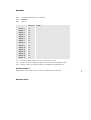
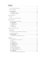


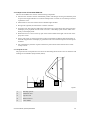
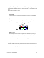


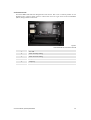
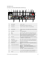
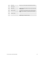

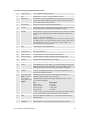
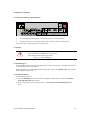


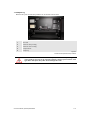


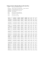
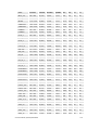


![Overview cPR67 and cPR84 [v00]](http://vs1.manualzilla.com/store/data/005648847_1-d158a5d3d4b92d14c7a3179652b88ffd-150x150.png)


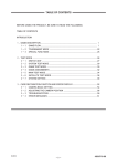


![OverView Control Manager user`s manual - operator [v04]](http://vs1.manualzilla.com/store/data/005659468_1-4c522981c7089838b286d7fbb1120c24-150x150.png)