1
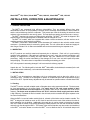
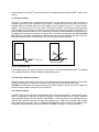
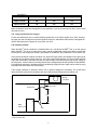
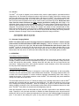
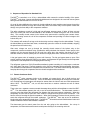
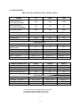
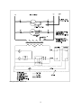
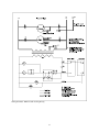
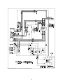
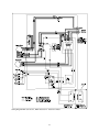
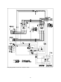
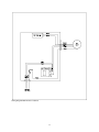
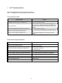
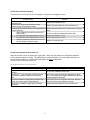
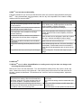
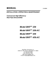
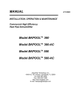
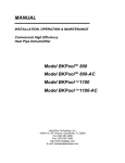
MANUAL
INSTALLATION, OPERATION & MAINTENANCE
Commercial High Efficiency
Heat Pipe Dehumidifier
Model BKPTM 750
Model BKPTM 750-AC
Model BKP¥ 1000
Model BKP¥ 1000-AC
Model BKP¥ 1250
Model BKP¥ 1250-AC
Heat Pipe Technology, Inc.
4340 N.E. 49th Avenue, Gainesville, FL 32609
Tel: (352) 367-0999
Fax: (352) 367-1688
http://www.heatpipe.com
E-mail: [email protected]
Model BKPTM 750, 750-AC, Model BKPTM 1000, 1000-AC, Model BKPTM 1250, 1250-AC
INSTALLATION, OPERATION & MAINTENANCE
1. GENERAL DESCRIPTION
The BKPTMs are commercial high efficiency dehumidifiers. They are radically different from other
dehumidifiers because of the proprietary heat pipe used to exchange heat between the warm intake air
and the cold air discharge from the evaporator. This process pre-cools the incoming air and allows more
moisture to be condensed for less energy spent. The heat pipes are passive devices that use no energy.
The BKPTM standard unit comes pre-charged with refrigerant. The BKPTM AC model is shipped in two
sections which must be piped together, evacuated and then charged as a unit.
The BKPTM AC models, which are equipped with outdoor remote condensers, will also work as an air
condition system to reject heat to the outdoors.
The BKPTM comes with a dehumidistat and a thermostat (AC models) for the unit with outside remote
condenser. Condensate water is removed by gravity drain. The unit comes with an intake and supply air
duct flanges. Pleated 2 in. air filters are standard and can be accessed through a separate cover.
2. INSPECTION
All HPT products are carefully tested and inspected prior to shipment. Each unit is in good working
condition when packaged. If the package is damaged in any way, check the contents immediately; note
damage on shippers Bill of Lading and have him/her sign your statement to insure prompt claim
processing. Notify the carrier immediately of the damage so he can come out and inspect the product
and packaging. The carrier alone is responsible for handling and settling your claim.
HPT will cooperate in assessing damage if unit is returned to the factory prepaid.
Unpack the unit. The following will be included: BKPTM dehumidifier, dehumidistat, thermostat (for the unit
with outside remote condenser), user's manual and warranty card.
3. INSTALLATION
The BKPTMs can be placed as a stand-alone unit in an environment such as above the ceiling or in a
mechanical room. The BKPTMs are designed to operate in conditioned space with temperatures ranging
from 60°F to 95°F. Special factory adjustments may be ordered for operation above or below these limits.
3.1 Ducting
The BKPTMs can be used with suitable metal or fiberglass ducts using approved methods. The ducts must
be sized appropriately for the airflow listed. If a supply duct is not used, some method of back
pressure on the blower must be supplied or the blower motor will be overloaded and could fail pre
maturely. The ducts must not add more than 0.5" E.S.P. inclusive of both supply and return ducts.
A high efficiency 2” pleated air filter is located in the air intake, and is accessible through a separate cover
for ease of maintenance.
When the BKPTM is used to handle outside fresh air, a branch of the intake can be ducted to outside. The
BKPTM is designed to handle as much as 25% fresh air and will remove most of the moisture from the air
before admitting it to the building. Additionally, the supply dry air can be ducted or injected to the supply
duct of the main air handler for a building providing the back pressure from the main air handler does not
reduce the air flow through the BKPTM . The blower of the main air handler may also need to be interlocked
to the BKPTM so that the blower runs when the BKPTM runs to distribute the air. A back draft damper will
2
also be needed for the BKPTM to prevent the main AC from blowing back through the BKPTM when it is not
running.
3.2 Condensate Drain
The BKPTM is supplied with a condensate gravity drain For the gravity drain, the pipe must have a
downward slope for the entire distance to the outside. If installed above the ceiling, the unit should be
installed above a secondary drain pan. Drain piping must be supported every 3 or 4 feet to prevent
sagging. If the line has any level runs or dips, it will not drain properly. Ensure that the drain line has a
trap, preferably at the low end of the drain, to prevent outdoor air from being aspirated into the BKPTM due
to the negative pressure inside the unit. A proper trap is required for the condensate to drain properly. If
the piping goes underground and back up outside, this is considered an adequate trap. Do not double
trap. This may prevent the condensate from draining due to the air pocket between two traps. Due to the
high static pressure across our dehumidifier coils, a 2 inch minimum trap is required.
BKP
BKP
Min. 2 in.
This will not Drain
Fig 3.2 Condensate Trap
For installation above the ceiling or above the ground floor, it is recommended that the BKPTM be installed
over a separate drain pan, which is piped to a separate drain point.
3.3 Units with a Remote Condenser
Install the remote condenser in an outdoor, well ventilated and preferably well-shaded area. Ensure that
the hot air discharge is not obstructed. Install on a concrete pad or as required by local codes.
CAUTION: The Condenser Coil is pressurized with a few PSI of nitrogen. Punch a hole in the copper cap
to relieve pressure before cutting off end to connect line.
3.4 Condenser Piping
The BKPTM with remote condenser is shipped with a holding charge of dry nitrogen. Release the pressure
before un-sweating the caps from the tubing connection. Connect the BKPTM to the remote condenser
using refrigerant tubing of the sizes listed in Table BKP01. The tubing needs not be insulated except in
exposed areas where the hot gas line might cause harmful burn. Solder the connections with suitable
silver brazing alloy and leak check. An additional Refrigeration charge will have to be added to the
nameplate charge depending on the liquid line size and length. See section 4. Charging the BKPTM
3
Table BKP01
Model
750-AC
1000-AC
1250-AC
Vapor Line OD
5/8
3/4
7/8
Liquid Line OD
1/2
5/8
5/8
Note: This BKP-AC remote line sizing applies to most applications, up to 50 feet horizontal, and within 10 feet vertical
(ACR OD line sizes).
3.41 Long Line Sets (50 ft or Longer)
For line sets where there are no vertical sections greater than 10 ft. and for lengths up to 150 ft. increase
the vapor line one size larger but leave the liquid line size as is. Also add 4 extra ounces of refrigerant oil
(3GS or Equivalent) to the system for every 50 ft. over 50 ft.
3.42 Vertical Line Sets
When the BKPTM remote condenser is installed either on a roof above the BKPTM Unit, or on the ground
where the BKPTM unit is on an upper floor or attic, special consideration needs to be taken to insure that
Oil will return to the compressor. Unlike a split system air conditioner, the compressor is in the indoor unit.
If the remote condenser is above the indoor unit, special P-Traps need to be installed in the vapor line at
the bottom of the vertical section and every 10 ft. above that. Small particles of oil that circulate with the
Vapor will accumulate in the traps until they are large enough to be carried up the pipe by the velocity of
the refrigerant. Vertical sections of tubing should not be enlarged beyond that specified in table BKP02.
Pre-manufactured traps are available at the air conditioning supply houses or traps can be made up using
long radius ells of the same size as the tubing.
If the remote condenser is below the indoor unit no special changes are necessary. The oil will travel
down hill with the vapor to the condenser and return with the liquid refrigerant to the indoor unit.
Remote
Condenser
Vapor Line
Liquid Line
10ft.
BKP
Indoor Unit
Trap
Fig 3.42 P-Traps must be added to vertical lines over 10 ft. where remote condenser is higher
than the indoor unit.
4
4. ELECTRICAL WIRING
CAUTION: Three Phase Model BKPstm Have Three Phase Scroll Compressors. These compressors
can be damaged by running backward. Verify correct compressor rotation by observing refrigerant
pressure gauges at startup. Little or no gauge movement indicates reverse rotation. Reverse any two
leads in the power junction box.
Note: Blower motor in BKP™ 750 and BKP™ 1000 is single phase and direction is not affected by lead
connections.
4.1 Power Supply
Use properly sized wire. Install and connect unit in accordance with local codes. Unit must be grounded.
Size separate circuits to the BKPTM and to the Remote Condenser. Condensers are single phase unless
special order.
4.2 24 VAC Control Wiring
Units Without Remote Condenser
A dehumidistat is supplied with the unit. It should be placed in the conditioned space away from heat
sources, entrance doors or any sources of humid air. Do not mount it directly on the side of the unit, as
the vibration may adversely affect it. Place the dehumidistat at a location where it could sense the
average relative humidity of the space.
The dehumidistat is of the 24 V type and should be wired with T-stat 18 gauge, low voltage wire. (See
wiring diagram in unit control panel.)
Units with Remote Condensers
For operation of units with a remote condenser, both temperature and humidity are controlled. A 24V
thermostat and a 24V dehumidistat are supplied with the BKPTM. Wire the controls with Thermostat 18
gauge low voltage wiring in accordance with the wiring diagrams.
NOTE: The operation of the remote condenser is by an internal pressure switch. No control wiring is
needed to the outdoor condenser.
5. Charging The BKPTM
The BKP™ is charged with refrigerant 22. The charge amount is listed on the nameplate. It is important to
have exactly the right charge in the unit or damage to the compressor or refrigerant components may
occur. Due to the wide range of operation of the BKP™ it is highly recommended that the charge be
weighed in to the ounce.
5.1 Standard Unit
Standard units (Non AC Models) are factory charged and ready to run after installation and wiring. If the
charge is in question, first, recover the refrigerant in the system and weigh in the proper charge. If it is
determined that the unit has a refrigerant leak, the leak must be repaired. Even though the unit appears to
operate, as the refrigerant level drops the compressor will over heat and be damaged before the condition
is recognized. Repair the leak and replace the liquid filter dryer. Evacuate the system using a Micron
Gauge down to 400 microns. Valve off the vacuum pump and insure the vacuum does not rise above 700
microns. Then weigh in the charge using a scale accurate to 1 once.
5
5.2 AC Unit
The BKPTM AC model is shipped in two sections which must be piped together, evacuated and then
charged as a unit. Evacuate the refrigerant system to 400 microns or below. Valve off the vacuum pump
and insure the micron level does not increase above 700 microns. For BKPTM -AC units the system must
be evacuated from all three ports. This is due to the check valves used in the remote condenser. A 1/4 in.
flair Tee and an extra refrigeration hose can be used to double up the discharge hose. Remove the extra
hose from the remote condenser tap after charging and before running the unit. Weigh in the
refrigerant charge using the suction and discharge ports. The proper charge of refrigerant 22 for the unit
and the remote condenser can be found on the nameplate. It is important to have the proper charge of
refrigerant. The preferred method of charging is to weigh in the charge from the nameplate with a scale,
which can be accurate to plus or minus one ounce. Additional refrigerant needs to be added for the length
of the line set. The liquid line (the smaller line) is full of liquid in both the heating and cooling modes of
operation. Measure the length of the line set one-way and add to the charge as follows:
1/2 in liquid line - add 1.5 oz per foot
5/8 in liquid line - add 2.5 oz per foot
5.3 Alternate Charging Method
NOTE: This method will only work if enough load can be maintained on the BKPTM that the suction
pressure does not fall below about 65 PSIG while charging. It will be necessary to remove the filter
access cover to observe the sight glass. Do not run the unit without the main covers in place. With
the BKPTM turned off, charge the unit with liquid until the unit can be run without shutting down on low
pressure. Start the unit in the heating mode and charge vapor into the low side port until the sight glass
almost clears. Run the unit for 15 minutes and then slowly add vapor until the sight glass just clears.
6. OPERATION
Units Without Remote Condenser
Set the dehumidistat at the desired level, the dehumidifier will run and remove humidity until the set
humidity is reached, at which time the dehumidifier will shut off. For normal operation, a range from 50%
to 60% will provide the best comfort. Settings below 50% will make the unit run longer and be less
economical. Settings above 60%, which may be required in certain situations, will be more economical
but may not provide adequate human comfort.
Units with Remote Condensers
The BKPTM-AC with remote condenser is designed to control space temperature as well as humidity.
Therefore, they are controlled by both a dehumidistat and a thermostat. This design allows the BKPTM-AC
to switch from normal operation to remote condenser operation automatically when extra cooling is
needed in the space. In the remote condenser mode, the BKPTM-ACs dehumidify and provide additional
cooling to the space at the same time.
The thermostat should be set 2 to 3°F below the setting on the building thermostat so that the BKPTM
operation will not interfere with the operation of the building A/C. The latter will continue to cycle on and
off to maintain the building temperature. When the building A/C cycles off, with the lower thermostat
setting, the BKPTM continues to run in the thermostat cooling mode until the temperature drops to its onset
point. The BKPTM then shifts to its normal mode, discharging dry warm air.
When the temperature rises to its thermostat set point, the BKPTM again shifts to the additional cooling
mode. Therefore, it will cycle back and forth to maintain the inside temperature at its set point and the
building A/C will not cycle on unless the temperature has risen up to the building's higher thermostat set
point. In this manner, the building A/C cycles on only when the cooling by the BKPTM is not sufficient.
6
When the relative humidity is down to the desired setting, the BKPTM -AC will shut off and the building will
be back to its normal A/C operation.
During the wintertime when the space must be heated, the BKPTM ‘s thermostat should be set 2 to 3
degrees above the main heating thermostat. This will use the BKPTM ‘s normal dehumidifying operation
mode to provide additional heating to supplement the building's heating system. It will continue in this
mode until its dehumidistat is satisfied.
NOTE: The BKPTM-AC is not designed to cool when the outdoor temperature is below 50°F.
Refrigerant Migration will occur and the unit will shut down on low pressure.
7.
MAINTENANCE
It is essential that the air filter on the inlet of the unit be kept clean in order to prevent excessive power
consumption and possible damage. Check the filters routinely to determine the frequency of replacement.
Keep the outdoor remote condenser free of leaves and grass clippings, which may impede air flow.
Check condensate drain regularly to ensure that the condensate is draining properly. If installed with an
auxiliary drain pan under the unit, check that it is dry.
It is recommended that the BKPTM be serviced annually by an authorized HPT certified technician to
provide maximum efficiency and insure long equipment life.
8. SERVICE DIAGNOSIS
The BKPTM is equipped with safety controls, which will shut down the unit if a problem occurs. The BKPTM
will remain locked out until it is reset.
If The Unit Locks out:
1. Check the air filter in the inlet of the unit. A dirty air filter will cause an increase in power consumption
and in the long run may cause damage to the unit.
2. Check the remote condenser. If the air is blocked or the hot air discharge is not free to dissipate, a
high discharge pressure will result and may cause damage to the BKPTM.
3. Check the power supply to the remote condenser. It will be on a separate breaker and if tripped will
cause the BKPTM to shut down.
4. If the problem cannot be determined, have the unit serviced by a qualified service technician. See
troubleshooting guide below.
To reset the BKPTM
Reset the BKPTM by either turning the humidistat all the way up and then back down or turning the power
to the BKPTM off and then on. Allow 5 minutes for the BKPTM to restart. If it locks out again after restart,
have the unit serviced by a qualified service technician to determine the cause of the shutdown and
correct the problem. See troubleshooting section below.
7
9. Sequence of Operation for Standard Unit
The BKPTM is controlled, on or off, by a dehumidistat which senses the relative humidity of the space.
The BKPTM units have a remote mounted dehumidistat and are designed to be used with a duct system
having a total external static of 0.5 in H2O or less.
On a call for dehumidification the contact in the dehumidistat is made sending control power through the
safety shutdown switches, through the lockout relay and to the blower relay. Control power is also sent
through a recycle time delay to the compressor contactor.
The safety shutdowns consist of a high and low refrigerant pressure cutout. If either of these cut-outs
open, the current path from the dehumidistat to the contactor is shifted through the coil of the lock-out
relay. The normally closed contact in the lockout relay opens and the normally open contact closes,
essentially shorting across the coil of the compressor contactor and providing full control voltage to the
lockout relay coil.
The contactor will remain off as long as the lockout relay receives voltage from the dehumidistat. Turning
the dehumidistat up and then back down, mechanically opens the contact in the dehumidistat, dropping
the power from the lockout relay.
After reset, voltage can now go through the normally closed contact of the lockout relay to the
compressor contactor and blower relay, provided the safety shutdown has cleared. Control power to the
contactor will be resumed through the off-cycle time delay when the machine has been off for the
selected number of minutes (factory set to 5 minutes for single phase units 3 minutes for 3 phase units).
A hot gas bypass valve is installed to prevent coil freeze-up. The hot gas bypass starts to open if the
suction pressure drops below 60 PSIG for any reason, and bypasses hot gas directly into the evaporator
to prevent the coil temperature from dropping below freezing.
The refrigerant system is a R-22 (Chlorodifluoromethane) system consisting of a compressor, condenser
coil, sight glass, filter dryer, Thermal expansion valve, and an evaporator with dehumidifier heat pipes.
The coil section contains both the evaporator and condenser coils. The airflow enters through the precool
heat pipe then through the evaporator then the reheat heat pipe and the condenser.
9.1
Remote Condenser Units
The BKP-ACTM series operates similar to the standard unit except that it has a liquid receiver and
employs a separate outdoor condenser. Since the standard unit discharges air through the condenser
coil, the discharge air temperature will always be warmer than the inlet air and can reach temperatures
above 100qF. The BKP-ACTM unit, on the other hand has an outdoor condenser as well an indoor
condenser.
These units use a separate remote mounted thermostat along with the dehumidistat to control the BKPACTM. The dehumidistat operates the unit on and off as described above. The thermostat controls a
reversing valve that diverts the refrigerant flow between the indoor and outdoor condensers. When the
temperature is below the set point, the valve sends the refrigerant through the indoor condenser. This
has the effect of warming the space temperature. When the temperature is above the set point the valve
sends the refrigerant through the outdoor condenser. The BKP-ACTM then acts as an air conditioner,
bringing the space temperature back down. The BKP-ACTM will switch back and forth between indoor and
outdoor condenser until the dehumidistat is satisfied.
The thermostat gets its control power from the red wire going to the dehumidistat. On a drop in
temperature, the thermostat contact sends control power directly to the reversing valve coil.
8
The outdoor condenser is powered from a separate power supply. No control voltage wiring is
connected. A head pressure switch inside the outdoor condenser controls the fan. The fan comes on
when the pressure in the outdoor coil reaches 240 psig and shuts off when it drops below 190 psig.
The refrigerant flows from the compressor to the reversing valve inlet. In the de-energized state the flow
is sent to the indoor condenser. The line going to the outdoor condenser is internally connected to the
reversing valve's center suction port, which is connected to the suction line coming out of the evaporator
by a 1/4" tube. This tube has a check valve installed in it. Any refrigerant in the outdoor condenser will
be pulled back through this 1/4" tube as the compressor runs. A check valve in the leaving liquid line of
the outdoor condenser prevents refrigerant from being pulled backward through the condenser coils.
When the reversing valve shifts to the outdoor condenser the indoor condenser is connected to the
suction by the 1/4" line. The indoor coil also has a check valve in the liquid line out.
The 1/4" line to the suction header provides a smoother transition when shifting. A hissing sound for 10
to 20 seconds is normal while the machine equalizes after shifting.
The BKP-ACTM also has a liquid receiver in the common liquid line.
If the BKP-ACTM is installed in an application where it may need to run in the winter when outdoor
temperatures will be below freezing, special provisions need to be made in the installation. An outdoor
thermostat must be installed to prevent the BKP-ACTM from shifting to the outdoor mode when
temperatures are below 50°F. If the unit is allowed to shift to the outdoor condenser when the
temperature is below that of the evaporator temperature, the compressor will not be able to pull the
refrigerant back when it shifts to the indoor coil and the unit will shut down on low pressure. A check
valve in the liquid line and in the small suction return line prevent refrigerant from migrating to the outdoor
coil during cold whether, while the unit operates in the Heating Mode.
9.2
OPTIONAL EQUIPMENT
9.21 Phase Loss Monitor for Three Phase Units
Units with a Phase loss monitor are provided with fuses which feed the phase loss monitor and the
control transformer. The monitor has an adjustable setting for operating voltage which determines the trip
settings. This voltage must be set at startup to the measured line voltage. This monitor samples the
voltage between all three phases and closes a set of normally open contacts when the voltage and phase
rotation is correct A red LED lights up to indicate the contact is closed. The contact will open if line
voltage on any phase drops by 10% of the adjusted line voltage setting or an unbalance of 4% occurs
between phases. The contact will open to drop the 24 V control power to the control system.
9.22
Cooling Priority Relay
Units with a cooling priority relay will energize the BKPTM in the cooling mode on a call for cooling from the
thermostat even if the dehumidistat is satisfied. Control voltage from the thermostat to the reversing valve
is used to energize the cooling relay. Normally open contacts 2 and 4 close to supply control power
directly from the transformer to the yellow wire coming from the dehumidistat. When the thermostat is
satisfied, the BKPTM will shut down again.
9
10. SPECIFICATIONS
BKPTM 750, 1000, 1250 BKPTM 750-AC, 1000-AC, 1250-AC
Models
750
1000
1250
Capacity (lbs/day) at
80°F & 60% RH (AHAM)
739
959
1250
Capacity (lbs/day) at
80°F & 50% RH (ASHRAE)
576
748
975
Air Flow Rate (CFM)
1200
1600
2000
Operating Range
All models can operate from 60°F/100% RH to 95°F/55% RH
Dimensions (WxHxD) (in.)
34 x 70 x 28
34 x 70 x 33
34 x 70 x 40
500
550
750
2) 20 x 25 x 2
2) 20 x 25 x 2
4) 16 x 20 x 2
Net Weight (lbs)
Filter Size (WxHxD) (in.)
Electrical (60 Hz)*
Voltage/Phase (Standard)
Max. Fuse or HACR Circuit
Breaker (Amps)
Min. Circuit Ampacity (Amps)
208/230V 1 ph**
208/230V 3 ph
208/230V 3 ph
70
70
80
47
47
49
Normal Operating Power (W)
6300 W
8400 W
9600 W
61,000 BTU Scroll
94,000 BTU Scroll
108,000 BTU Scroll
DD12X12 / 3/4
DD12X12 / 1
BD12X12 / 1 1/2
Optional
Optional
Optional
750-AC
1000-AC
1250-AC
Dimensions (WxHxD) (in.)
Net Weight (lbs)
Air Flow Rate (CFM)
Vapor Line Connection (in.)
Liquid Line Connection (in.)
47.5 x 29 x 24
150
4000
5/8
1/2
47.5 x 37 x 24
150
4000
3/4
5/8
49.5 x 37 x 25.5
260
6000
7/8
5/8
Voltage/Phase
Fan Blade
Size / HP
Normal Operating Power (W)
Min. Circuit Ampacity (Amps)
Electrical (60 Hz)*
208/230V 1 ph
208/230V 1 ph
24” 27° / 3/4
24” 27° / 3/4
800 W
800 W
3.0
3.0
208/230V 1 ph
24” 33° / 1
1000 W
5.0
Compressor
Blower
Size / HP
Condensate Pumps
Models (Outdoor Unit)
*50 Hz mode*50 Hz models available on custom order.
**Three-phase models available on custom order.
Specifications subject to change without notice.
10
TM
BKP
TM
and BKP-AC
SERIES TROUBLESHOOTING CHECK LIST
Supply
Air
Company: ____________________________
Phone: (____) _______ Fax: (____) _______
Model # : __________ Serial # : __________
Remote
Condenser
BKP
Job Name: ____________________________
Return
Air
Test performed by: _________ Date: _______
Test
Dehumidification
Return Air Flow
Return Air Temperature
Air Conditioning
CFM
°F DB
°F WB
CFM
°F DB
°F WB
Air
Return Air Static Pressure (Negative)
in. WG
Return Duct Size
Supply Air Temperatures
" Depth
°F DB
" Width
°F WB
°F DB
°F WB
Supply Duct Air Pressure (Positive)
In. WG
Supply Duct Size
" Depth
" Width
Condensate (see Note below)
Elec.
Refrigerant
High Discharge Pressure / Sat.
Temperature
Liquid Line Temperature / Sight Glass
psig
°F
psig
°F SG Clear? ❏
Low Suction Pressure / Saturated
Temperature
Psig
°F SG Clear? ❏
°F
psig
°F
Suction Line Temperature (@coil outlet)
°F
°F
Suction Superheat
°F
°F
Compressor
Volts/Amps at
outdoor °F
Indoor Blower ❏Lo Med Hi
Volts/Amps
Amps at
°F DB
Amps at
Volts
°F DB
Amps
Outdoor Fan ________ Volts / Amps
BKP-AC
°F
Amps
ON: _______ psig
OFF: _______ psig
Outdoor Fan Pressure Switch set at
Vapor Line Length / Size
ft
"OD
Liquid Line Length / Size
ft
"OD
Note: To perform condensate flow test, run the unit for 15 minutes, then capture condensate for 5
minutes in a graduated container. Air side conditions must be measured during this time.
Is condensate TRAP properly installed? ❏ Yes. ❏ No.
11
Wiring Schematic BKP and AC
12
Wiring Schematic BKP AC With Cooling Priority
13
Wiring Diagram BKP 750 and AC 208/230V Single Phase
14
Wiring Diagram BKP 750 and AC, BKP 1000 and AC 208/230V 3 Phase
15
Wiring Diagram BKP 1250 and AC 208/230V 3 Phase
16
Wiring Diagram BKP Remote Condenser
17
11.
BKP
TM
TROUBLESHOOTING
Follow each applicable section in order from top to bottom.
Note 1 - Acceptable control voltage range 22 volts to 30 volts.
1) The unit does not start.
Possible Cause
Solution
No power to the unit.
Humidistat set above space humidity level.
Check the voltage to unit at the top of contactor.
Lower the humidistat setting.
Reset the BKPTM by turning the dehumidistat up and
then down. then wait for time delay. If the BKPTM locks
out again Follow Procedure #3 “Unit locks out before
starting”
If no, replace the transformer
If no, make sure the dehumidistat and field wiring are
OK.
If yes, Follow Procedure #2 “Unit locks out before
starting”
If the unit locks out
Check if the transformer has 24V. (see note 1)
Check for 24V at lockout terminals 3 & 2
Check for 24V at lockout terminals 1 & 3.
2) Fan runs but compressor doesn’t
Possible Cause
Solution
Check Voltage at bottom of compressor contactor
If yes wait 5 minutes. If compressor does not start,
replace the time delay
If yes and the contactor does not pull in, then replace
the compressor contactor
If no check wiring
If no, Replace contactor.
Check for proper voltage at compressor terminals
If no, Repair wiring from contactor to compressor.
Compressor is hot
Compressor off on internal overload. Let it cool down.
Check capacitor
Replace if bad.
Check compressor ohms
Replace if bad.
Check for 24v across time delay
Check for 24v at the compressor contactor coil
18
3) Unit locks out before starting.
Turn power off to unit for this section. Put gauges on high and low refrigeration ports.
.
Possible Cause
If both gauges are below 40 psig, the unit has a
refrigerant leak
Low pressure gauge below 40 psig and high
pressure gauge at saturation pressure
If Low pressure is above 40 psig, and high pressure
is below 250 psig,
check continuity from wire to terminal 3 of
lockout relay.
No continuity across low pressure cut out.
No continuity across high pressure cut out.
If there is continuity across all cut outs then
the wire between cutouts is open.
Solution
Repair and recharge the unit.
Replace thermal expansion valve and filter dryer.
Remove wire from terminal 5 of lockout relay. Continue
below.
If there is continuity, replace the lockout relay.
Replace low pressure cutout.
Replace high pressure cutout.
Replace or repair the wire.
4) Unit runs a short time then locks out.
Remove the Filter Cover to observe the sight glass. Start unit and observe the refrigerant pressures.
The low pressure cutout is 15 psig. The high pressure cutout is 350 psig. If the unit tries to shut down on
the low pressure switch, try to observe the sight glass just before it shuts down.
Do not run the unit with the cover(s) off.
4a) Unit shuts down on low pressure.
Possible Cause
Insure inlet air conditions are above 70°F and 45%
humidity
For BKP-ACTM units check that unit does not shift
into cooling if outdoor conditions are less than
50°F.
If there are bubbles in sight glass just before shut
down, the unit may have a refrigerant leak.
If there are no bubbles in sight glass just before
shut down,
19
Solution
Do not run if conditions are too low.
Do not run in cooling if outdoor temperature is below
50°F. if necessary install outdoor thermostat to prevent
cooling operation below 50°F.
Leak check, Recover refrigerant and repair. Replace
filter dryer. Evacuate and weigh in charge.
Replace thermal expansion valve and filter dryer.
4b) Unit shuts down on high pressure.
Possible Cause
Check for proper airflow.
Solution
Replace filter, clean coil, duct and blower.
Let ice melt and check for proper operation of the hot
gas bypass
If air flow is low, check that the coil is not icing up.
For BKP-ACTM, the outdoor fan does not come on
at 240 psig in cooling mode because there is no
power to outdoor condenser.
Pressure switch operation does not work.
Fan motor not running.
If pressure is still high, unit has probably been
overcharged.
NOTE: Proper charge cannot always be
determined by refrigerant pressures, and the sight
glass can show bubbles under normal conditions.
Restore the power.
Replace the pressure switch.
Repair wiring to the motor and/or replace the fan motor.
Recover all refrigerant and weigh in proper charge.
5) Unit shuts down occasionally.
Follow the procedure under (4) "unit runs a short time then locks out". If unit shuts down, follow the
outlined procedure. An occasional shut down can be a very difficult problem to diagnose. It usually
involves some trial and error and multiple trips back to solve. If everything looks normal while the machine
is running, consider whether there could be any environmental changes taking place during the day.
Such as the air conditioning or heating being shut down at night while the BKPTM runs continuously. If it is
a BKP-ACTM, the unit could be tripping on cold nights when it shifts to the outdoor condenser. These units
should be prevented from running in the cooling mode if the outdoor temperature is below 50°F.
Small trip indicators are available from local AC supply houses to help in diagnosis. These are attached
across each safety cut out and will tell you which control is shutting the system down. This will narrow
down the possibilities. Do not permanently bypass any safety control unless directed by the factory.
20
6) BKPTM runs but does not dehumidify.
Follow the procedure in (4) "unit runs a short time then locks out" to observe sight glass while running the
BKPTM. Using thermometers and hygrometers, take the dry bulb temperature and relative humidity
readings at the air inlet to the BKPTM.
Possible Cause
Solution
Check compressor wiring, and capacitor. If compressor
is hot, allow to cool. OHM compressor to determine
winding condition. Replace compressor
Check if the hot gas bypass is leaking by.
High and low pressure gauges did not move when
the unit comes on.
If the compressor runs, but low pressure reads too
high and high pressure reads too low.
Check if the evaporator coil is frosted up. If frost is
present, allow the frost to melt completely. Check hot
gas bypass
If the compressor runs, but both low and high
pressure reads low
If pressures are still low, and there are bubbles in
the sight glass, the unit may have a refrigerant
leak.
If pressures are still low and there are no bubbles
in sigh glass.
If high press reads high and low pressure is ok or
high.
Check for leak, recover refrigerant, repair leak, replace
filter dryer, evacuate and weigh in proper change.
Replace thermal valve and filter dryer.
If no problems are found, unit may be overcharged.
Check airflow through the unit. If it is low, check filter
and ductwork. External static should not exceed 0.5“
Check that air inlet temperatures are not too hot or too
humid.
Recover refrigerant. Evacuate and weigh in proper
charge.
For BKP-ACTM
7) BKP-ACTM runs in either dehumidification or cooling mode only but does not change mode
(reversing valve does not shift).
Remove the cover from the thermostat. Turn the temperature setting all the way up then all the way
down. Observe the mercury in the glass bulb. If the mercury does not move from one end of the bulb to
the other, replace the thermostat. If the bulb does not “rock over” at the current temperature, replace the
thermostat.
Remove either wire from the time delay to keep the
compressor from starting. With the thermostat all the
way down, check for 24 V at the reversing valve coil.
Do not run the BKPTM compressor without a cover.
If you have voltage to the reversing valve coil, have
someone turn the thermostat up and down as you listen
for a definite "click" in the reversing valve.
21
If yes, then the reversing valve coil or the valve
itself is bad.
If no, check the wiring to the thermostat and to the
BKP
If The valve clicks but does not shift, replace the
reversing valve
If the valve does not click replace the solenoid coil.
BKP™ and BKPool™ Series Packaged Dehumidifier
Twelve-Month Limited Warranty
Subject to the following conditions, Heat Pipe Technology, Inc. (HPT), warrants this product to be free from defects in material and
workmanship for a period of TWELVE MONTHS from the date of installation, not to exceed 90 days from date of shipment. This warranty is in
lieu of all other warrants not expressly set forth herein, whether expressed or implied by operation of law or otherwise. In the event this product
fails under normal use and service within the applicable period, HPT will correct, repair or, at its sole discretion, replace the defective product or
refund the purchase price of products which are returned freight prepaid to HPT for inspection, when accompanied by proof of purchase and
written claims of defect, and which upon inspection by HPT, do comply with the terms of this warranty.
This warranty applies to the first retail buyer and extends to any subsequent owners of the systems.
Additional Three-Year Limited Warranty On Compressor
(Packaged Equipment Only)
Additionally, HPT warrants the COMPRESSOR to perform under normal use and conditions for a period of THREE YEARS from the date of
completion of installation, not to exceed 90 days from date of shipment, when installed in accordance with factory instructions and
recommendations. In the event the compressor malfunctions or fails to perform during this warranty period, HPT will repair or, at its option,
replace the compressor at the pro-rated schedule of cost shown below:
Percentage of repair or replacement cost paid by Heat Pipe Technology, Inc.
Month of Claim
1 - 12
13 - 24
25 - 36
Percentage
100%
66%
33%
The cost of replacement parts or components shall be determined by the price schedule in effect at the time of submission of warranty claim.
Repair or replacement parts will be furnished F.O.B. factory in all cases.
If HPT elects to replace or provide a refund, the defective product must be returned to HPT free and clear of liens or other encumbrances.
Limitations on Liability
A.
B.
C.
D.
E.
F.
This warranty does not cover and no warranty is made with respect to:
Failures not reported to HPT within the period specified above;
Failures or damage due to misapplication, misuse, abuse, improper storage or handling, abnormal conditions of temperature, water, dirt,
corrosive substances or other contaminants;
Products which have been repaired with parts or materials not furnished or approved by HPT or by its authorized dealers or
representatives, or products which have been in any way tampered with or altered; and
Products damaged in shipment or storage or otherwise without fault of HPT.
Failure of the product resulting from modifications to the product or due to unreasonable use including failure to provide reasonable and
necessary maintenance. Failure due to corrosion on models not corrosion protected. Damage to the product caused by improper power
supply voltage, accident, fire, floods, or acts of God. WARRANTOR IS NOT RESPONSIBLE FOR CONSEQUENTIAL DAMAGES.
HPT total responsibility for any claims, damages, losses or liabilities related to the product covered hereunder shall not exceed the purchase
price of such product. In no event shall HPT be liable for any special, indirect, incidental or consequential damages of any character, including
but not limited to loss of use of productive facilities or equipment, lost profits, property damage, transportation, installation or removal, lost
production, or personal injury whether suffered by Purchaser or any third party. HPT disclaims all liability for any and all costs, claims,
demands, charges, expenses or other damages, either direct or indirect, incident to personal injury or property damage arising out of any cause
of action based on strict liability.
Some states do not allow the exclusion or limitation of incidental or consequential damages or limitations on how long an implied warranty
lasts, so the exclusion or limitation above of consequential damages or the limitation of time above on implied warranties may not apply to you.
This warranty gives you specific legal rights and you may have other rights which may vary from state to state.
22
Warranty Registration
To insure your warranty protection, please fill in the Warranty Registration form and mail or fax it to:
Heat Pipe Technology, Inc.
4340 NE 49th Avenue, Gainesville, FL 32609
Fax: (352) 367-1688
WARRANTY REGISTRATION FORM
Customer Name:
Customer Address:
Phone: (
)
-
Please Check One:
Fax: (
Homeowner
Model No:
)
-
Dealer
Serial No:
Type of Product:
Date of Installation:
Dealer/Installer:
Name & Address of Dealer/Company You Purchased from
Name:
Address:
Customer Signature:
23