1
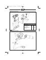
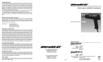
HL1610S_USA
20.05.2005
15:40 Uhr
Seite 2
HL 1610 S
HL 1810 S
HL 1910 E
HL 2010 E
HG 2310 LCD
HG 2510 ESD
i
HL1610S_USA
20.05.2005
15:40 Uhr
Seite 3
English
IMPORTANT SAFETY INSTRUCTIONS
READ THESE INSTRUCTIONS
UL WARNING: Read this instruction book before using. To reduce risk of fire or electric
shock, do not expose to rain or moisture. Store indoors. Double insulated. When servicing,
use only identical replacement parts. When using electric tools, basic safety precautions
should always be followed to reduce risk of fire, electric shock and personal injury. This hot
air gun operates at 1200°F with no visual indication of temperature (no flame). Never leave
device unattended. Otherwise risk of fire. The heat stream at the outlet nozzle will burn flesh.
Do not turn on heat gun with hand in front of nozzle. DO NOT USE NEAR COMBUSTIBLE LIQUIDS. DO NOT USE FOR: ● Heating gas engines ● Heating car batteries ● Thawing
refrigerator equipment.
WARNING:
Some dust created by power sanding, sawing, grinding, drilling and other
construction activities contains chemicals known (to the State of California) to cause cancer,
birth defects, or other reproductive harm. Some examples of these chemicals are:
● lead from lead-based paints,
● crystalline silica from bricks and cement and other masonry products, and
● arsenic and chromium from chemically-treated lumber.
Your risk from these exposures varies, depending on how often you do this type of work.
To reduce your exposure to these chemicals: work in a well ventilated area, and work with
approved safety equipment, such as those dust masks that are specially designed to filter out
microscopic particles.
WARNING!
This tool is capable of producing temperatures up to 1200° F of flameless heat
at the nozzle. ALWAYS:
● Direct the heat away from yourself and others.
● Prevent ignition of combustible materials on or near the workpiece.
● Prevent blockage of intake and nozzle openings.
● Keep a fully charged fire extinguisher on hand.
● Allow the nozzle and accessory tips to cool to room temperature before storage.
Cautions
1. WARNING: Hidden areas such as behind walls, ceilings, floors, soffit boards and other
panels may contain flammable materials that could be ignited by the heat gun when
working in these locations. The ignition of these materials may not be readily apparent and
could result in property damage and injury to persons. Do not use if in doubt about this
hazard. When working in these locations, keep the heat gun moving in a back-and-forth
motion. Lingering or pausing in one spot could ignite the panel or the material behind it.
2. This heat gun can produce up to 1200° F of flameless heat at the nozzle. Do not direct
airstream at clothing, hair or other body parts. Do not use as a hair dryer.
3. Do not use near flammable liquids or in an explosive environment (fumes, gases or dust).
Remove materials or debris, that may become ignited, from work area.
4. Always hold tool by plastic enclosure. The metal nozzle requires approximately 20 minutes
to cool to where it can be touched. Do not touch nozzle or accessory tips until cool.
5. Do not store tool until nozzle has cooled to room temperature. Place tool in a clear area
away from combustible materials while cooling.
6. Do not cut off airflow by placing nozzle too close to workpiece. Keep intake vents clean
and clear of obstructions.
7. Place tool on a level surface with the support rubber ring when tool is not hand held.
Place cord in a position that won’t cause tipping.
8. Do not leave tool unattended while running or cooling down. Otherwise risk of fire.
9. Keep a fully charged fire extinguisher nearby.
10. Do not direct airflow directly on glass.
11. Shield materials around the heated area to prevent damage or fire.
12. Use only with 120 V AC voltage.
13. Do not use in wet conditions.
14. Not to be used by children. This is not a toy and should be respected.
15. Do not use in bath or over water.
16. Safety glasses should be worn when using this tool.
17. It is recommended that leather gloves be worn when using a heat gun.
-2-
HL1610S_USA
20.05.2005
15:40 Uhr
Seite 4
English
18. Always unplug after use.
19. WARNING: Extreme care should be taken when stripping paint. The peelings, residue and
vapors of paint may contain lead, which is poisonous. Any pre-1977 paint may contain lead
and paint applied to homes prior to 1950 is likely to contain lead. Once deposited on surfaces, hand to mouth contact can result in the ingestion of lead. Exposure to even low
levels of lead can cause irreversible brain and nervous system damage; young and unborn
children are particularly vulnerable. Before beginning any paint removal process you should
determine whether the paint you are removing contains lead. This can be done by your
local health department or by a professional who uses a paint analyzer to check the lead
contact of the paint to be removed. LEAD-BASED PAINT SHOULD ONLY BE REMOVED BY
A PROFESSIONAL AND SHOULD NOT BE REMOVED USING A HEAT GUN.
Persons removing materials should follow these guidelines.
1. Move the work piece outdoors. If this is not possible, keep the work area well ventilated.
Open the windows and put an exhaust fan in one of them. Be sure the fan is moving the air
from inside to outside.
2. Remove or cover any carpets, rugs, furniture, clothing, cooking utensils and air ducts.
3. Place drop cloths in the work area to catch any residue. Wear protective clothing such as
extra work shirts, overalls and hats.
4. Work in one room at a time. Furnishings should be removed or placed in the center of the
room and covered. Work areas should be sealed off from the rest of the dwelling by sealing
doorways with drop cloths.
5. Children, pregnant or potentially pregnant women and nursing mothers should not be present
in the work area until the work is done and all clean up is complete.
6. Wear a dust respirator mask or a dual filter (dust and fume) respirator mask which has been
approved by the Occupational Safety and Health Administration (OSHA), the National Institute
of Safety and Health (NIOSH), or the United States Bureau of Mines. These masks and
replaceable filters are readily available at major hardware stores. Be sure the mask fits.
Beards and facial hair may keep masks from sealing properly. Change filters often.
DISPOSABLE PAPER MASKS ARE NOT ADEQUATE.
7. Use caution when operating the heat gun. Keep the heat gun moving as excessive heat will
generate fumes which can be inhaled by the operator.
8. Keep food and drink out of the work area. Wash hands, arms and face and rinse mouth
before eating or drinking. Do not smoke or chew gum or tobacco in the work area.
9. Clean up all removed residue and dust by wet mopping the floors. Use a wet cloth to clean
all walls, sills and any other surface where residue or dust is clinging. DO NOT SWEEP, DRY
DUST OR VACUUM. Use a high phosphate detergent or trisodium phosphate (TSP) to wash
and mop areas.
10. At the end of each work session put the residue and debris in a double plastic bag, close it
with tape or twist ties, and dispose of properly.
11. Remove protective clothing and work shoes in the work area to avoid carrying dust into the
rest of the dwelling. Wash work clothes separately. Wipe shoes off with a wet rag that is then
washed with the work clothes. Wash hair and body thoroughly with soap and water.
SAVE THESE INSTRUCTIONS
-3-
HL1610S_USA
20.05.2005
15:40 Uhr
Seite 5
English
Double Insulated Tools
Tools marked with the words “Double Insulated” are equipped with a two prong plug.
These tools have a special insulation system that complies with applicable UL standards
. They do not require grounding. ”Double Insulated” tools, like this one, have
two prong cords and can use either a two or three prong extension cord.
“This appliance has a polarized plug (one blade is wider than the other). To reduce
the risk of electric shock, this plug is intended to fit in a polarized outlet only one
way. If the plug does not fit fully in the outlet, reverse the plug. If it still does not fit,
contact a qualified electrician. Do not modify the plug in any way.”
Extension Cords
As the distance from the supply outlet
increases, heavier gauge extension cords
are required. The use of extension cords of
inadequate size wire causes a serious drop
in voltage and loss of power. Protect the cord
from damage. Keep cords away from excessive heat, sharp edges and damp or wet
areas. Repair or replace damaged extension
cords before using.
Ext. Cord Length
Wire Size
040 Ft.
085 Ft.
100 Ft.
170 Ft.
270 Ft.
400 Ft.
650 Ft.
16
14
12
10
08
06
04
Note: The HG 2510 ESD is not ”Double Insulated”. It utilizes a 3-prong grounded
plug and, for safety, must only be used with a 3-prong extension cord.
-4-
HL1610S_USA
20.05.2005
15:40 Uhr
Seite 6
English
Thank you
for deciding to choose a STEINEL
heat gun. This tool can be used
for completing a wide range of
jobs safely and reliably, such as
soldering, welding PVC, shaping,
drying, shrink-fitting, stripping paint
etc. All STEINEL tools are manufactured to the highest standards
and undergo a strict process of
quality control.
Used in the proper manner, this
heat gun will give you lasting
satisfaction.
Technical specifications
HG 2510 ESD
HG 2310 LCD
HL 1910 E
HL 2010 E
HL 1610 S
HL 1810 S
Voltage
120 V, 60 Hz
120 V, 60 Hz
120 V, 60 Hz
Output
1600 W
1600 W
1500 W
Switch stage
1
2
1
2
1
2
3
1
2
3
1
2
3
1
2
Airflow (cf/min.)
3.6
3.6 – 17.6
3.6
3.6 – 17.6
3.6
10.6
17.6
3.6
10.6
17.6
3.6
10.0
15.9
8.5
14.8
Temperature
120 °
120 – 1200 °F 120 °
750°
1100 °F 575 °
Controls
pushbutton
air/temperature control
in 10 °F increments,
with LCD display
pushbutton
air/temperature control
in 10 °F increments,
with LCD display
pushbutton
temperature control
in 10 °F increments,
with LCD display
temperature dial
4 preset programs,
with ”LOC” Lockable
Override Control™
4 preset programs,
with ”LOC” Lockable
Override Control™
–
–
Programs
120 – 1200 °F 120 °
1300 W
1400 W
1500 W
120 – 1150 °F 120 °
120 V, 60 Hz
120 V, 60 Hz
120 V, 60 Hz
120 – 1100 °F 120 °
–
–
–
–
950 °F
Subject to technical modifications
Conversion °C to °F
Conversion °F to °C
°C
= °F
°F
100
212
100
38
200
392
200
93
300
572
300
149
400
752
400
204
500
932
500
260
600
1112
600
316
700
1292
700
371
-5-
= °C
800
427
900
482
1000
538
1100
593
1200
649
HL1610S_USA
20.05.2005
15:40 Uhr
Seite 7
English
Features - Getting started
Please note: The distance from the object you are working on depends on material and intended method
of working. Always try out the airflow and temperature on a test piece first! Using the attachable accessory
nozzles (see accessories page on the cover) the flow of heat can be controlled with maximum precision.
Take care when changing hot nozzles! When using the heat gun in the self-resting position, make sure
it is standing on a stable, non-slip and clean surface.
HL 1610 S
The tool is switched ON and OFF at the two-stage switch on the back of the grip handle. Airflow and temperature can be adjusted to 2 settings. Stage 1 reaches 575 °F at an air flow of 8.5 cf/min, stage 2 reaches
950 °F at 14.8 cf/min.
HL 1810 S
The tool is switched ON and OFF at the three-stage switch on the back of the grip handle. Airflow and
temperature can be adjusted to 3 settings. Stage 1 is a Cool air stage at 120 °F with an airflow rate of
3.6 cf/min. Stage 2 reaches 750 °F at an airflow of 10.0 cf/min., stage 3 delivers 1100 °F at 15.9 cf/min.
The outlet protection tube can be removed in order to install the overhead security hanger.
HL 1910 E
The tool is switched ON and OFF at the three-stage switch on the back of the grip handle. In addition to threestage speed/airflow control (stage 1 is a ”Cool-air stage” at 120 °F ), temperature can be continuously adjusted
over a range of 120 °–1100 °F at the thumbwheel. The numbers (1 to 9) on the thumbwheel serve as a guide
only. Whereas ”1” means 120 °F, the maximum temperature of 1100 °F is attained at ”9”.
Airflow can be adjusted to the three stages of 3.6/10.6/17.6 cf/min. The outlet protection tube can be removed
in order to install the overhead security hanger.
Temperature
Dial Setting
Temperature
Range °F
Temperature
Range °C
71.1 °C
Sample
Applications
cleaning surfaces
1
100 – 160 °F
37.8 –
2
200 – 300 °F
93.3 – 148.9 °C
3
375 – 475 °F 190.6 – 246.1 °C
shaping/removing flooring materials
4
475 – 575 °F 246.1 – 301.7 °C
welding PE, LDPE, PP, thawing pipes
activating adhesives
5
600 – 700 °F 315.6 – 371.1 °C welding ABS, PBT, PC; lap welding plastic sheeting
6
725 – 825 °F 385.0 – 440.6 °C
de-soldering circuit boards
7
850 – 950 °F 454.4 – 510.0 °C
stripping paint, loosening nuts/screws
8
975 – 1075 °F 523.9 – 579.4 °C
de-soldering copper pipes
9
1025 – 1125 °F 551.7 – 607.2 °C
soldering
HL 2010 E
The tool is switched ON and OFF at the three-stage switch on the back of the grip handle. In addition to threestage speed/airflow control, temperature can be continuously adjusted over a range of 120 °–1150 °F by the
pushbuttons. The target temperature can be increased in 10 °F steps by pressing the ”+” side of the temperature pushbutton or reduced by pressing the ”–” side of the temperature pushbutton. Pressing the button briefly
increases or reduces the target temperature by one 10 °F step. Keeping the button pressed will continue to
increase or reduce the temperature in steps of 10 °F until the button is released or the minimum or maximum
temperature is set.
Blower stage 1 delivers a temperature of 120 °F. The tool will take a short while to cool to 120 °F after switching
down to blower stage 1 when it has been operating at high temperatures on blower stage 2 or 3. While the
tool is cooling down, the LCD display shows the actual temperature at the nozzle outlet. After switching OFF,
the tool stays in the last setting. The outlet protection tube can be removed in order to install the overhead
security hanger.
-6-
HL1610S_USA
20.05.2005
15:40 Uhr
Seite 8
English
Features - Getting started
HG 2310 LCD / HG 2510 ESD
Operation
The tool is switched ON and OFF
at the multi-stage switch on the
back of the grip handle. The distance from the object you are
working on depends on material
and intended method of working.
Always try out the air flow and
temperature on a test piece first.
Using the attachable accessory
nozzles the flow of heat
can be controlled with maximum
precision. Take care when
changing hot nozzles!
When using the heat gun in the
self-resting position, make sure it
is standing on a stable, non-slip
and clean surface. The outlet protection tube can be removed in
order to install the overhead security hanger.
display. The red push button on
the left-hand side is used as an
input button with minus/plus function. Temperature settings range
from 120 °F to 1200 °F
max. Briefly pressing the “+” / “–”
push button increases or reduces
the temperature setting in 10 °
steps. Pressing the button for
longer speeds up the temperature
setting process. Once the tempera-
ture has been set, the tool takes a
few seconds to reach temperature
(depending on speed/airflow). If
you want to alter the setting, simply
press either button to increase or
reduce the temperature. After
switching OFF, the heat gun stays
in the last setting.
The grey button panel on the right
below the display is used for regulating airflow and blower speed.
Airflow can be controlled in sever-
al stages using the “+/–” function
and can be varied from a minimum of 3.6 cf/min. to a maximum of 17.6 cf/min. Use the cool
air stage function for drying paint,
cooling workpieces or to cool the
nozzle before changing an accessory attachment.
Programming [P]
Default programs
Setting the temperature
Stage 1 is the cool air stage. Use
the cool air function for drying
paint, cooling workpieces or to
cool the nozzle before changing
an accessory attachment.
In stage 2 temperature can be
infinitely varied over a range of
120 °F to 1200 °F on the control
panel with LCD display. The actual
temperature is measured at the
nozzle outlet and indicated on the
Setting airflow
Four programs are factory-set for
the most common types of work.
Press button “P” for programming
mode. Number 1 is displayed for
program 1. Continuing to press
the program button will take you
to programs 2 – 4. Pressing the
button again will return the tool to
normal operation.
Program
Temp. °F
Air cf/min.
Application
1
480
approx. 12.4
Shrink tubing
2
660
approx. 14.8
De-soldering circuit boards
3
860
approx. 17.6
Forming plastics
4
1000
approx. 14.8
Soldering
Memory function [S]
The settings for the four programs
can be changed and saved at any
time. To do this, press the first program button “P” until the display
shows the program you wish to
change. Set the chosen airflow
and temperature. Now press the
memory button “–>” until the “–>”
symbol is cleared from the display
(approx. 5 sec). The values
entered are now saved in the
program memory. To return to
normal operation, press the
program button until the program
symbol disappears from the
display.
ture/airflow combination using the
”LOC” Lockable Override Control™
feature.
Please call (800) 852-4343 for
more information.
”LOC” function
Authorized quality Control personnel may lock down the heat gun’s
output to one specific tempera-
-7-
HL1610S_USA
20.05.2005
15:40 Uhr
Seite 9
English
Applications
Here are some of the applications
you can use STEINEL heat guns
for. This selection is by no means
exhaustive – no doubt you can
immediately think of other examples.
F Soft soldering: First, clean
metal parts you want to join. Then,
heat the point you want to solder
and offer up the soldering wire.
Use flux or a soldering wire with a
flux core to prevent oxide forming.
A Stripping paint: Paint is softened and can be removed with a
stripping knife and paint scraper
to leave a clean surface.
G Welding and joining plastic:
All parts being welded must be of
the same plastic material. Use an
appropriate welding rod.
B Shrinking tubing on cables:
The shrink tubing is slipped over
the section you want to insulate
and heated. The tubing shrinks
by approx. 50% in diameter to
give a sealed union. Shrinking
is particularly fast and even using
reflector nozzles. Sealing and
stabilizing cable breaks, insulating
soldered joints, gathering cable
runs, sheathing terminal blocks.
H De-soldering: Circuit boards
and other electronic components
may be soldered or de-soldered
using a reduction tip fitted on an
electronic heat gun.
I Joining sheeting: The sheets
are overlapped and welded
together. A slit nozzle is used to
direct heat under the overlap,
then the two sheets are firmly
pressed together with a feed
roller. Also possible: Repairing
PVC tarpaulins by overlap welding with a slit nozzle.
Material
Application types
Distinguishing characteristics
Rigid PVC
Pipes, fittings, sheets, building profiles, technical mouldings
Welding temperature 580 °F
Floor coverings, wallpapers,
hoses, sheets, toys
Welding temperature 760 °F
Domestic and electrotechnical
articles, toys
Welding temperature 480 °F
Baths, baskets, canisters, insulating material, pipes
Welding temperature 580 °F
HT drainage pipes, moulded
seats, packaging, car components
Welding temperature 480 °F
Car components, equipment
housings, cases
Welding temperature 660 °F
Carbonizes in the flame, pungent odour;
crashing sound
C Forming PVC: Sheeting, piping or ski boots can be softened
and formed with heat.
Plasticised
PVC
D Lighting the barbecue:
Gets charcoal glowing in next to
no time; no more waiting.
(LDPE)
Polyethylene
E Thawing: Water pipes, frozen
door locks, steps. Gently thaws
and dries all in one go.
PP
Soft PE
Hard PE
(HDPE)
Polyethylene
Polypropylene
ABS
Smoking, yellowish-green flame,
pungent odour; silent
Light yellow flame, drips continue
to burn, smells of a candle being
extinguished; dull sound
Light yellow flame, drips continue
to burn, smells of a candle being
extinguished; crashing sound
bright flame with a blue core,
drips continue to burn, pungent odour;
crashing sound
black, fluffy smoke, sweet odour;
crashing sound
J Accessories
Your dealer has a wide range of accessories for you to choose from. (* for HL 1910 E, HL 2010 E, HG 2310 LCD
and HG 2510 ESD only)
1 Spreader nozzle, 75 mm
Prod. No. 07011
8 Deflector nozzle, 75 mm
Prod. No. 07031
13 Reflector nozzle, 75 mm
Prod. No. 07301
20 Angle slit nozzle
Prod. No. 07511
2 Spreader nozzle, 50 mm
Prod. No. 07021
9 Deflector nozzle, 50 mm
Prod. No. 07041
14 Reflector nozzle, 39 mm
Prod. No. 07051
21 Wire protection tube
Prod. No. 07402
3 Butt welding disc,
80 mm*
Prod. No. 07211
10 Seam roller, 45 mm
Prod. No. 01250
15 Reflector nozzle, 14 mm*
Prod. No. 07461
11 Plastic welding rods
Prod. No.
Rigid PVC
07311
LDPE
07331
HDPE
07121
PP
07341
ABS
07421
16 Reflector nozzle, 9 mm
Prod. No. 07061
4 Lap welding slit tip
Prod. No. 07471
5 Welding rod tip
Prod. No. 07091
6 Lap welding slit tip
Prod. No. 07101
7 Rod welding slit tip
Prod. No. 07201
12 Overhead Security
Hanger
Prod. No. 01481
17 Reducer nozzle,
9 mm*
Prod. No. 07062
18 Reducer nozzle, 14 mm*
Prod. No. 07071
19 Reducer nozzle, 20 mm*
Prod. No. 07081
-8-
HL1610S_USA
20.05.2005
15:40 Uhr
Seite 10
English
HL 1610 S / HL 1810 S / HL 1910 E / HL 2010 E / HG 2310 LCD / HG 2510 ESD
920 - 1100 °F
480 - 920 °F
480 - 580 °F
A
B
C
480 - 580 °F
920 - 1100 °F
1100 °F
F
E
D
HL 1910 E / HL 2010 E / HG 2310 LCD / HG 2510 ESD
650 - 750 °F
480 - 760 °F
G
580 - 760 °F
H
I
J Accessories
21
-9-
HL1610S_USA
20.05.2005
15:40 Uhr
Seite 11
English
Tool
elements
/ spare
parts
Spare
Parts List
HL 1610
S list HG 2310 LCD
9
10
1
2
11
7
3
8
6
5
4
Pos.
Part No.
1+2
3
4+5
6
7
8
9
10
11
02816
02416
02723
—
02829
02316
02216
02116
02417
HL 1610 S, Type 3480
Housing Set incl. Labels
Switch with Markings (external)
Power Cord with Strain Relief
Power Cord Connector
Set of 5 Housing Screws
PCB/IC Block with Switch (internal)
Motor/Fan Assembly
Heating Element 1300W/120V
Switch (internal)
Wiring Diagram HL 1610 S
blue
red
red
violet
yellow
black
white
- 10 -
HL1610S_USA
20.05.2005
15:40 Uhr
Seite 12
English
Spare Parts List HL 1810 S
5
1
13
14
15
6
2
11
3
4
12
7
8
9
Pos.
Part No.
1 +2
3
4
5
6
7
8 + 10
9
11
12
13
14
15
02818
—
02420
02621
02523
02629
02723
—
02829
02318
02218
02118
02426
HL 1810 S, Type 3481
10
Housing Set incl. Labels
End Cap
Switch with Markings (external)
Softgrip
Outlet Protection Tube
Rubber Soft Stand
Power Cord with Strain Relief
Power Cord Connector
Set of 5 Housing Screws
PCB/IC Block with Switch (internal)
Motor/Fan Assembly
Heating Element 1400W/120V
Switch (internal)
Wiring Diagram HL 1810 S
red
blue
blue
red
yellow
white
black
- 11 -
HL1610S_USA
20.05.2005
15:40 Uhr
Seite 13
English
Spare Parts List HL 1910 E
1
4
12
13
7
2
10
14
3
11
5
6
Pos.
Part No.
1+2
3
4
5
6+8
7
9
10
11
12
13
14
02819
02420
02621
02629
02723
02523
—
02829
02319
02225
02120
02426
HL 1910 E, Type 3484
9
Housing Set incl. Labels
Switch with Markings (external)
Softgrip
Rubber Soft Stand
Power Cord with Strain Relief
Outlet Protection Tube
Power Cord Connector
Set of 5 Housing Screws
PCB/IC Block with Switch and End Cap
Motor/Fan Assembly
Heating Element 1500W/120V
Switch (internal)
8
Wiring Diagram HL 1910 E
2:1
white
red blue
yellow
black
red
blue
green
yellow (fuse)
- 12 -
HL1610S_USA
20.05.2005
15:40 Uhr
Seite 14
English
Spare Parts List HL 2010 E
1
4
12
13
7
2
10
14
3
11
5
6
Pos.
Part No.
1+2
3
4
5
6+8
7
9
10
11
12
13
14
02820
02420
02621
02629
02723
02523
—
02829
02320
02225
02120
02426
HL 2010 E, Type 3482
9
Housing Set incl. Labels
Switch with Markings (external)
Softgrip
Rubber Soft Stand
Power Cord with Strain Relief
Outlet Protection Tube
Power Cord Connector
Set of 5 Housing Screws
PCB/IC Block with Switch and Controls
Motor/Fan Assembly
Heating Element 1500W/120V
Switch (internal)
8
Wiring Diagram HL 2010 E
red
2:1
white
blue
yellow
black
red
blue
green
yellow (fuse)
- 13 -
HL1610S_USA
20.05.2005
15:40 Uhr
Seite 15
English
Spare Parts List HG 2310 LCD
1
4
12
13
7
2
10
14
3
11
5
6
Pos.
Part No.
1+2
3
4
5
6+8
7
9
10
11
12
13
14
02823
02423
02621
02629
02723
02523
—
02829
02323
02225
02123
02426
HG 2310 LCD, Type 3483
9
Housing Set incl. Labels
Switch with Markings (external)
Softgrip
Rubber Soft Stand
Power Cord with Strain Relief
Outlet Protection Tube
Power Cord Connector
Set of 5 Housing Screws
PCB/IC Block with Switch and Controls
Motor/Fan Assembly
Heating Element 1600W/120V
Switch (internal)
8
Wiring Diagram HG 2310 LCD
red
2:1
white
blue
yellow
black
red
blue
green
yellow (fuse)
- 14 -
HL1610S_USA
20.05.2005
15:40 Uhr
Seite 16
English
Spare Parts List HG 2510 ESD
1
4
12
13
7
2
10
14
3
11
5
6
Pos.
Part No.
1+2
3
4
5
6+8
7
9
10
11
12
13
14
02825
02425
02621
02629
02725
02525
—
02829
02325
02225
02125
02426
HG 2510 ESD, Type 3488
9
Housing Set incl. Labels (ESD)
Switch with Markings (external)
Softgrip
Rubber Soft Stand
Power Cord with Strain Relief (ESD)
Outlet Protection Tube (ESD)
Power Cord Connector
Set of 5 Housing Screws
PCB/IC Block with Switch and Controls (ESD)
Motor/Fan Assembly
Heating Element 1600W/120V (ESD)
Switch (internal)
8
Wiring Diagram HG 2510 ESD
green
red
2:1
white
blue
yellow
black
red
blue
green
yellow (fuse)
- 15 -
HL1610S_USA
20.05.2005
15:40 Uhr
Seite 17
English
Limited Warranty
STEINEL warranties its heat guns and glue guns, if properly operated and maintained, and used under normal conditions, for a period of one (1) year from the
date of purchase. For heat guns, this warranty includes the heating element.
Specifically EXCLUDED from warranty are tools that have been subject to abuse,
tools that have been opened or repaired by anyone other than STEINEL, tools
that have been modified in any way or mounted onto machinery/equipment, and
tools that have been put into continuous operation. These are hand held power
tools and are intended for use as such. Any other use voids STEINEL’s warranty.
Warranty and Repair Procedures
In the event of product failure, please call STEINEL customer service directly
at (800) 852-4343. We will attempt to troubleshoot the difficulty via phone.
If warranty work or other repair appears necessary, we will issue an RGA#
and ask that the tool be returned to us at the below address (postage paid
by the customer), with the RGA# clearly marked, and accompanied by a brief
description of the difficulty as well as your original dated sales receipt phone
number and return address.
When received, STEINEL will diagnose the problem and determine if it is
covered under warranty. If we determine that it is covered by warranty, we will
repair or replace the defective tool, at our option, and return it to the customer
(postage paid by STEINEL). If we determine that the tool is not defective and/
or that it is not covered by warranty, we will contact the customer to discuss
his options prior to performing any repair work not covered under warranty.
All non-warranty repair work is billed at standard rates and will be quoted prior
to repair.
Consequential Damages
The company shall not be liable for any incidental or consequential damages
arising from the use of the Product by the Purchaser, the breach of any warranties, the failure to deliver, delay in delivery, delivery in non-conforming condition, or for any other breach of contract or duty between the Company and
the Purchaser.
Some states do not allow the exclusion or limitation of incidental or consequential damages, so the above limitation or exclusion may not apply to you.
- 16 -
HL1610S_USA
20.05.2005
15:40 Uhr
Seite 18
English
Disclaimers of warranties
The warranties contained herein are expressly in lieu of any other expressed
or implied warranties, or any other obligation on the part of the Company.
Any implied warranty of merchantability or fitness for a particular purpose
shall expire one (1) year after the date the product is purchased by the
original end-user Purchaser. Any models, drawings, plans, specifications,
affirmations of fact, promises, or other communications by the Company with
reference to the performance of the product are solely for the convenience
of the Purchaser and shall not in any way modify the expressed warranties
and disclaimers set forth herein. The Purchaser acknowledges it is purchasing
the Product solely on the basis of the commitments of the Company as
expressly set forth herein. No agents or other parties are authorized to make
any warranties on behalf of the Company or to assume for the Company any
other liability in connection with the Product. Some states do not allow
limitations on how long an implied warranty lasts, so the above limitation
may not apply to you.
Limitation of actions
Any action resulting from the breach of any warranty contained herein by
the Company must be commenced within one (1) year after the cause of
action accrues. In no event shall the Company’s total liability for any or all
breaches of any warranty exceed the actual purchase price of the Product.
Other rights
This warranty gives you specific legal rights, and you may also have other
rights which vary from state to state.
STEINEL
9051 Lyndale Avenue South
Bloomington, MN 55420
Tel.: 952-888-5950
Fax: 952-888-5132
Toll free: 1-800-852-4343
E-mail: [email protected]
Visit our website: www.steinel.net
- 17 -
20.05.2005
15:40 Uhr
German Quality
0000000 Subject to technical change without prior notice
HL1610S_USA
Seite 1