1
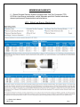
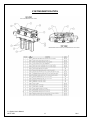
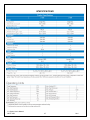
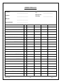
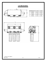
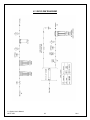
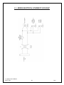
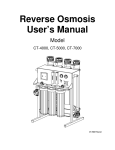
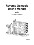
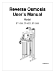
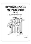
Membrane System
User’s Manual
L1-Series
This Page
Left Blank
L1-Series User’s Manual
MKTF-258
2
9/14
TABLE OF CONTENTS
INTRODUCTION ....................................................................................................................................... 4
SAFETY ..................................................................................................................................................... 5
FEED WATER AND OPERATION SPECIFICATIONS .................................................................................... 6
REJECTION, RECOVERY AND FLOW RATES .............................................................................................. 7
SYSTEM INSTALLATION AND START-UP PROCEDURES ............................................................................ 8
MEMBRANE ELEMENTS ......................................................................................................................... 10
SYSTEM IDENTIFICATION ....................................................................................................................... 11
MEMBRANE INSTALLATION, REMOVAL AND REPLACEMENT ............................................................... 12
OPERATION DO’S AND DON’TS ............................................................................................................. 14
SPECIFICATIONS..................................................................................................................................... 15
OPERATION AND MAINTENANCE .......................................................................................................... 16
PREPARING UNIT FOR STORAGE OR SHIPMENT.................................................................................... 17
REVERSE OSMOSIS TROUBLESHOOTING ............................................................................................... 18
TEMPERATURE CORRECTION FACTORS FOR MEMBRANE .................................................................... 20
SERVICE ASSISTANCE ............................................................................................................................. 21
OPERATION LOG .................................................................................................................................... 22
SYSTEM DRAWING................................................................................................................................. 23
L1-200 SERIES FLOW DIAGRAM............................................................................................................. 24
L1 - SERIES ELECTRICAL SCHEMATIC 110V/60HZ .................................................................................. 24
L1 - SERIES ELECTRICAL SCHEMATIC 220V/50HZ .................................................................................. 26
REVERSE OSMOSIS SYSTEM WARRANTY ............................................................................................... 27
L1-Series User’s Manual
MKTF-258
3
9/14
INTRODUCTION
Your L1 - Series RO System is a durable piece of equipment which, with proper care,
will last for many years. This User’s Manual outlines installation, operation,
maintenance and troubleshooting details vital to the sustained performance of your
system.
If your system is altered at the site of operation, or if the feed water conditions
change, please consult your local dealer or distributor for assistance.
NOTE: IN ORDER TO MAINTAIN THE MANUFACTURER’S WARRANTY,
AN OPERATING LOG MUST BE MAINTAINED AND COPIES WILL NEED TO BE
SENT TO YOUR LOCAL DEALER OR DISTRIBUTOR FOR REVIEW.
NOTE: PRIOR TO OPERATING OR SERVICING THE REVERSE
OSMOSIS SYSTEM, THIS USER’S MANUAL MUST BE READ AND FULLY
UNDERSTOOD. KEEP THIS AND OTHER ASSOCIATED INFORMATION FOR
FUTURE REFERENCE AND FOR NEW OPERATORS OR QUALIFIED
PERSONNEL NEAR THE SYSTEM.
L1-Series User’s Manual
MKTF-258
4
9/14
SAFETY
The Safety section of this User’s Manual outlines the various safety headings used
throughout this manual’s text and are enhanced and defined below:
NOTE: INDICATES STATEMENTS THAT PROVIDE FURTHER INFORMATION
AND CLARIFICATION.
CAUTION: INDICATES STATEMENTS THAT ARE USED TO IDENTIFY
CONDITIONS OR PRACTICES THAT COULD RESULT IN EQUIPMENT OR
OTHER PROPERTY DAMAGE.
WARNING: INDICATES STATEMENTS THAT ARE USED TO IDENTIFY
CONDITIONS OR PRACTICES THAT COULD RESULT IN INJURY OR LOSS OF
LIFE. FAILURE TO FOLLOW WARNINGS COULD RESULT IN SERIOUS INJURY
OR EVEN DEATH.
DO NOT UNDER ANY CIRCUMSTANCE REMOVE ANY CAUTION,
WARNING, OR OTHER DESCRIPTIVE LABELS FROM THE SYSTEM.
PLEASE READ THE ENTIRE MANUAL BEFORE PROCEEDING WITH
THE INSTALLATION AND STARTUP. YOUR FAILURE TO FOLLOW
ATTACHED INSTRUCTIONS OR OPERATING PARAMETERS MAY LEAD TO
THE PRODUCT’S FAILURE, WHICH CAN CAUSE PROPERTY DAMAGE
AND/OR PERSONAL INJURY.
•
DO NOT USE WHERE THE WATER IS MICROBIOLOGICALLY
UNSAFE OR OF UNKNOWN QUALITY WITHOUT ADEQUATE
DISINFECTION BEFORE OR AFTER THE SYSTEM.
•
PRETREATMENT MUST BE SUFFICIENT TO ELIMINATE
CHEMICALS, ORGANICS OR INORGANICS THAT COULD ATTACK
THE MEMBRANE MATERIAL.
•
ALWAYS TURN OFF THE UNIT, SHUT OFF THE FEED WATER, AND
L1-Series User’s Manual
MKTF-258
5
9/14
DISCONNECT THE ELECTRICAL POWER BEFORE WORKING ON
THE UNIT.
•
NEVER ALLOW THE PUMP TO RUN DRY.
•
NEVER ALLOW THE UNIT TO FREEZE OR OPERATE WITH A FEED
WATER TEMPERATURE ABOVE 100°F.
FEED WATER AND OPERATION SPECIFICATIONS
Nothing has a greater effect on a reverse osmosis system than the feed water
quality.
NOTE: IT IS VERY IMPORTANT TO MEET THE MINIMUM FEED WATER
REQUIREMENTS. FAILURE TO DO SO WILL CAUSE THE MEMBRANE TO
FOUL AND VOID THE MANUFACTURER’S WARRANTY.
OPERATING LIMITS
Operating Parameters:*
Feed Temperature
40 - 85°F
System Inlet Pressure
45 - 85 PSIG
Maximum Operating Pressure (@77°F)
120 PSIG (Nominal)
*If any of the feed water parameters are not within the limits given, consult your local dealer or
distributor for assistance.
Feed Water Requirements:**
Maximum SDI Rating
<3
Maximum Turbidity
1 NTU
Maximum Free Chlorine and/or Chloramines
0 PPM
pH (continuous)
3 - 11
pH (cleaning - 30 min.)
2 - 12
**If any of the feed water parameters are not within the limits given, consult your local dealer or
distributor for assistance.
NOTE: HIGHER TDS AND/OR LOWER TEMPERATURES WILL REDUCE
THE SYSTEM’S PRODUCTION.
L1-Series User’s Manual
MKTF-258
6
9/14
REJECTION, RECOVERY AND FLOW RATES
L1 - Series Reverse Osmosis Systems are designed to produce permeate water at
the capacities indicated by the suffix in the system’s name under the conditions listed
above. For example, the L1-300 produces 300 gallons per day of permeate water at
the listed operating test conditions.
The amount of total dissolved solids (TDS) rejected by the membrane is expressed
as a percentage. For example, a 98.5% rejection rate means that 98.5% of total
dissolved solids do not pass through the membrane. To calculate the % rejection,
use the following formula:
% Rejection = [(Feed TDS – Product TDS) / Feed TDS] x 100
Example:
98.5% = [(550-8.25)/550] x 100
NOTE: ALL TDS FIGURES MUST BE EXPRESSED IN THE SAME UNITS,
TYPICALLY PARTS PER MILLION (PPM) OR MILLIGRAMS PER LITER (MG/L).
L1 - Series Reverse Osmosis Systems are designed to reject up to 98.5% NaCl,
unless computer projections have been provided or stated otherwise.
The amount of permeate water recovered for use is expressed as a percentage. To
calculate % recovery, use the following formula:
% Recovery = (Product Water Flow Rate / Feed Water Flow Rate) x 100
Example:
28% = (0.14/0.50) x 100
NOTE: ALL FLOW RATES MUST BE EXPRESSED IN THE SAME UNITS,
TYPICALLY GALLONS PER MINUTE (GPM).
L1-Series User’s Manual
MKTF-258
7
9/14
SYSTEM INSTALLATION AND START-UP PROCEDURES
1. Inspect the system for any damage that could have occurred during shipment. Although
our systems have been individually inspected, complete a quick inspection of the fittings,
tubing and other components.
2. Please provide a reasonable amount of space for installation and leave 6 inches of space
below the filter housings for ease of maintenance.
NOTE: THE REVERSE OSMOSIS SYSTEM SHOULD BE INSTALLED
INDOORS AND IT IS SUGGESTED THAT IT NOT BE IN DIRECT SUNLIGHT OR
EXTREME COLD.
3. Connect the 3/8” tube fitting to an incoming water source. The minimum water pressure
should be at least 30 psi. The system’s minimum operating pressure is 80 PSI, but the
optimum operating pressure is 100 psi.
NOTE: DO NOT OPERATE AT A PRESSURE EXCEEDING 125 PSI. The
operating pressure can be increased on the face of the booster pump by turning the hex
screw clockwise.
4. Connect the concentrate 3/8” tubing (waste) line to drain.
5. Plug the booster pump transformer into a power supply of 110 volts 60 Hz.
6. This system has been designed with an auto-flush restrictor. This restrictor automatically
flushes the reverse osmosis system for 30 seconds every time it starts up and once every
hour when the system is producing water.
NOTE: THE TANK PRESSURE SWITCH WILL SHUT THE SYSTEM OFF
AUTOMATICALLY WHEN THE BLADDER TANK IS FULL.
L1-Series User’s Manual
MKTF-258
8
9/14
7. The sediment filter and carbon must be serviced regularly for optimal performance. The
filters and water quality should be checked every two weeks minimum.
8. Dispose of the product water until the conductivity of the product water reaches your
desired level. Use any TDS or Conductivity meter to monitor the product water quality. A
minimum quality of 96% NaCl rejection is recommended.
NOTE: ANY CHLORINE EXPOSURE WILL DAMAGE THE MEMBRANE
PERMANENTLY.
9. This system has been factory wired and preset with a pressure switch at 20 - 40 psi,
which is only to be used with a pressurized bladder tank. If using an atmospheric storage
tank, a float switch will be required to turn the system on and off.
L1-Series User’s Manual
MKTF-258
9
9/14
MEMBRANE ELEMENTS
L1 - Series Reverse Osmosis Systems equipped with Thin Film Composite (TFC)
HF4 Extra Low Energy membranes, unless otherwise specified. General membrane
element performance characteristics are listed below.
HF4 – Extra Low Energy Membranes
L1-Series User’s Manual
MKTF-258
10
9/14
SYSTEM IDENTIFICATION
L1-Series User’s Manual
MKTF-258
11
9/14
MEMBRANE INSTALLATION, REMOVAL AND REPLACEMENT
Installation and replacing membranes in the pressure vessels is an easy process if
you have the proper information and tools at hand. Please refer to the following
instructions when removing and replacing membrane elements:
WARNING: ALL PRESSURE GAUGES MUST READ ZERO BEFORE
PROCEEDING. BEFORE ATTEMPTING, DISCONNECT THE POWER FROM THE
SYSTEM AND BLEED ALL WATER PRESSURE FROM THE SYSTEM.
1. Remove the end cap from the right (feed water) side of the membrane
housings. This is done by removing the two half-moon retaining disks using a
#5 Allen wrench, the end plug should then freely slide out of the pressure
vessel.
2. Remove the membrane bag containing the membrane element from the
shipping box. The membrane should be contained within a plastic oxygen
barrier bag.
NOTE: WEAR GLOVES FOR THE FOLLOWING STEPS IN ORDER NOT TO
CONTAMINATE THE MEMBRANE.
3. Cut the bag open as close as possible to the seal at one end of the bag, so the
bag may be re-used if necessary.
4. Make sure that all parts are clean and free from dirt. Examine the brine seal,
and permeate tube for nicks or cuts. Replace the O-rings or brine seal if
damaged.
5. Flow directions should be observed for installation of the membrane element
into the pressure vessels.
REPLACING THE MEMBRANE ELEMENT:
WARNING: THE BRINE SEAL MUST BE IN THE SAME POSITION AS IT WAS
FOR FACTORY PRE-INSTALLED MEMBRANE ELEMENT. THE BRINE SEAL IS A
L1-Series User’s Manual
MKTF-258
12
9/14
RUBBER SEAL THAT PROTRUDES ON ONE SIDE OF THE MEMBRANE AND IS
ALWAYS ON THE FEED SIDE OF THE MEMBRANE ELEMENT. FOR L1 SERIES RO
SYSTEMS THE BRINE SEAL SHOULD BE ON THE RIGHT SIDE OF THE MEMBRANE
HOUSING.
1. Remove membrane element from the right (feed water) side of the membrane
housing. Long nose pliers may be necessary to pull the old membrane
element out of the membrane element housing.
2. Lubricate the brine seal and o-rings with a non-petroleum based lubricant,
such as Dow Corning® 111. Do not use a petroleum-based lubricant.
3. Install membrane through the right side (feed water) of the membrane housing
with brine seal located on the feed water side.
4. With a smooth and constant motion, push the membrane element into the
housing so the brine seal enters the housing without coming out of the brine
seal groove.
5. Re-install the end plug (6, Figure 1.A) on the right side by gently twisting the
end cap, while pushing it onto the housing. Ensure that you do not pinch or
fatigue any o-rings while re-installing the end plug. Push the end plug on until
the outer diameter of the plug is flush with the outer diameter of the pressure
vessel.
6. Insert the two half-moon retaining disks until they are fully seated.
Subsequently fasten using a #5 Allen wrench.
7. Reconnect any fittings that may have been disconnected when the membrane
pressure vessels were disassembled.
8. To Start-Up the system, please refer to the Initial Start-Up section of this
manual.
CAUTION: WET MEMBRANES ARE SHIPPED IN A PRESERVATIVE
SOLUTION. THE MEMBRANES MUST BE FLUSHED FOR AT LEAST 30
MINUTES TO REMOVE THE PRESERVATIVE FROM THE MEMBRANE.
DISCARD ALL OF THE PERMEATE, WHICH IS PRODUCED DURING THE
FLUSH PERIOD.
L1-Series User’s Manual
MKTF-258
13
9/14
OPERATION DO’S AND DON’TS
DO:
•
Change the cartridge filters regularly
•
Monitor the system and keep a daily log
•
Run the system as much as possible on a continuous basis
•
Always feed the pump with filtered water
DON’T
•
Permit chlorine to enter membrane housing with the feed water
•
Shut down the system for extended periods
•
Operate the system with insufficient feed flow
•
Operate the pump dry
L1-Series User’s Manual
MKTF-258
14
9/14
SPECIFICATIONS
L1-Series User’s Manual
MKTF-258
15
9/14
OPERATION AND MAINTENANCE
The reverse osmosis process causes the concentration of impurities. The impurities
may precipitate (come out of solution) when their concentration reaches saturation
levels.
NOTE: PRECIPITATION CAN SCALE OR FOUL MEMBRANES AND MUST
BE PREVENTED.
1. Periodically observe the quality and quantity of product water from the system.
NOTE: CHECK THE FEED WATER PRESSURE GOING INTO THE REVERSE
OSMOSIS MEMBRANE, A SIGNIFICANT DROP IN PRESSURE COULD INDICATE A
FOULED PRE-FILTER.
2. A 20% increase in TDS when checking the permeate water indicates possible membrane
damage, and the membrane may need to be replaced.
3. It is suggested that a hand held TDS digital meter is used once per week to monitor the
water quality.
NOTE: IF THE TDS OF THE FEED WATER EXCEEDS 1000 PPM, A LARGER
FLOW RESTRICTOR SHOULD BE USED TO EXTEND THE MEMBRANE LIFE.
4. It is important to maintain and/or replace the carbon block regularly since the Thin Film
Composite membranes are chlorine sensitive. Irreversible damage will occur with any
chlorine present in the feed water. For additional information, please review the
manufacturer’s membrane specification sheets.
5. The product line has a one way check valve installed. The check valve should be
checked regularly and replaced if it is not properly sealing.
6. Keep the feed water temperature above 4°C (36°F).
NOTE: EXTREMELY COLD FEED WATER WILL LOWER THE PRODUCT
WATER OUTPUT AND INCREASE PUMP PRESSURE.
L1-Series User’s Manual
MKTF-258
16
9/14
PREPARING UNIT FOR STORAGE OR SHIPMENT
Prior to shipping or storing your system, the system should be cleaned
with an appropriate cleaner, flushed with water and protected from biological
attack with an appropriate solution for membrane elements. The membrane
housing(s) and plumbing lines of the system must be completely drained. Any
water remaining in the plumbing of a system may freeze, causing serious
damage.
Preparing system for storage:
1. Totally fill membrane elements in the membrane housing with 2 % M-100
solution, venting the air outside of the pressure vessels. Use the overflow
technique: circulate the M-100 solution in such a way that the remaining air in
the system is minimized after the recirculation is completed.
2. Check the pH once a week. When the pH becomes 3 or lower, change the
preservation solution.
3. Repeat this process at least once a month.
During the shutdown period, the plant must be kept frost-free, or the temperature
must not exceed 113°F (45°C).
Preparing unit for shipment:
4. Disconnect the inlet, concentrate, pre-filter, and permeate plumbing.
5. Drain all water from the pre-filter cartridge housings by unscrewing the
housings, removing the pre-filter cartridges, and drain the water from the
housings.
6. Disconnect the tubing from the connectors on the permeate and concentrate
inlets and outlets.
Allow the system to drain for a minimum of eight hours or until the opened ports quit
dripping.
After draining is complete, reconnect all of the plumbing.
L1-Series User’s Manual
MKTF-258
17
9/14
REVERSE OSMOSIS TROUBLESHOOTING
SYMPTOMS
Low Inlet Pressure
Low Permeate Flow
High permeate flow
Poor permeate quality
POSSIBLE CAUSES
Low supply pressure
Increase inlet pressure
Cartridge filters plugged
Change filters
Solenoid valve malfunction
Replace sol. valve and/or coil
Motor may not be drawing correct current
Use clamp-on amp meter to check the
motor amp draw.
Leaks
Fix any visible leaks
Cold feed water
See temperature correction sheet
Low operating pressure
See low inlet pressure
Defective membrane brine seal
Inspect and/or replace brine seal
Fouled or scaled membrane
Clean membranes
Damaged product tube o-rings
Inspect and/or replace
Damaged or oxidized membrane
Replace membrane
Exceeding maximum feed water
temperature
See temperature correction sheet
Low operating pressure
See low inlet pressure
Damage product tube o-rings
Inspect and/or replace
Damaged or oxidized membrane
Replace membrane
Metal Oxide Fouling
Colloidal Fouling
Scaling (CaSO4, CaSO3, BaSO4, SiO2)
Membrane fouling
Biological Fouling
Improve pretreatment to remove metals.
Clean with acid cleaners.
Optimize pretreatment for colloid
removal. Clean with high pH anionic
cleaners.
Increase acid addition and antiscalant
dosage for CaVO3 and CaCO4. Reduce
recovery. Clean with acid cleaners
Shock dosage of Sodium Bi-Sulfate.
Continuous feed of Sodium Bi-Sulfate at
reduced pH.
Chlorination and de-chlorination.
Replace cartridge filters.
Organic Fouling
Activated Carbon or other pretreatment.
Clean with high pH cleaner.
Chlorine Oxidation
Check Chlorine feed equipment and dechlorination system.
Abrasion of membrane by Crystalline
Material
L1-Series User’s Manual
MKTF-258
CORRECTIVE ACTION
18
Improve pretreatment. Check all filters
for media leakage.
9/14
ABNORMAL PERMEATE FLOW
Permeate flow should be within 20% of the rated production, after correcting the feed
water temperatures above or below 77°F. Check your permeate flow meter to
determine the permeate flow rate.
NOTE: TO DETERMINE THE TEMPERATURE CORRECTION FACTOR,
LOCATE THE TEMPERATURE CORRECTION TABLE IN THIS USER’S MANUAL
AND FOLLOW THE DIRECTIONS.
L1-Series User’s Manual
MKTF-258
19
9/14
TEMPERATURE CORRECTION FACTORS FOR MEMBRANE
Find the temperature correction factor (TCF) from the table below. Divide the rated
permeate flow at 77°F by the temperature correction factor. The result is the
permeate flow at the desired temperature. (See example on the next page)
If a system is rated to produce 5 gpm of permeate water @ 77˚ F, the same system
will produce more water at a higher temperature. It will also produce less water at a
lower temperature. Use the temperature correction table to obtain the correct flow.
L1-Series User’s Manual
MKTF-258
20
9/14
Example:
5 gpm @ 59˚ F (5÷1.42=3.52 gpm)
5 gpm @ 77˚ F (5÷1=5 gpm)
5 gpm @ 84˚ F (5÷0.89=5.62 gpm)
SERVICE ASSISTANCE
If service assistance is required, please complete the following process:
Contact your local dealer or distributor. Prior to making the call, have the following
information available: system installation date, serial number, daily log sheets,
current operating parameters (e.g. flow, operating pressures, pH, etc.) and a detailed
description of the problem.
L1-Series User’s Manual
MKTF-258
21
9/14
OPERATION LOG
Company:
Location:
____________________
Date of StartUp:
___________________
____________________
Date of Last
Cleaning:
___________________
Week Of:
____________________
System Serial #:
____________________
DATE
TIME
HOUR OF OPERATION
FILTER INLET PRESSURE (PSI)
FILTER OUTLET PRESSURE (PSI)
CONCENTRATE PRESSURE (PSI)
PUMP DISCHARGE PRESSURE (PSI)
FEED FLOW (GPM)
PERMEATE FLOW (GPM)
CONCENTRATE FLOW (GPM)
RECOVERY %
FEED TEMPERATURE
FEED TDS (PPM)
PERMEATE TDS (PPM)
REJECTION %
FEED PH
PERMEATE PH
SCALE INHIBITOR FEED (PPM)
IRON (mg/L)
FREE CHLORINE (mg/L)
HARDNESS (GPG CaCO3)
L1-Series User’s Manual
MKTF-258
22
9/14
SYSTEM DRAWING
L1-Series User’s Manual
MKTF-258
23
9/14
L1-300 FLOW DIAGRAM
L1-Series User’s Manual
MKTF-258
24
9/14
L1 - SERIES ELECTRICAL SCHEMATIC 110V/60HZ
L1-Series User’s Manual
MKTF-258
25
9/14
L1 - SERIES ELECTRICAL SCHEMATIC 220V/50HZ
L1-Series User’s Manual
MKTF-258
26
9/14
REVERSE OSMOSIS SYSTEM WARRANTY
One-Year Limited Warranty
Warranty Terms
Subject to the terms and conditions set forth hereinafter, AXEON Water Technologies
(hereafter “AXEON”) warrants to the original purchaser (hereafter the “Customer”)
that the systems and products manufactured by AXEON are free from defects in
material and in workmanship for twelve (12) months from the Warranty
Commencement Date (as defined below) only when used strictly in accordance with
the applicable operating instructions and within the range of the operating conditions
specified by AXEON for each such product.
This Warranty does not extend to systems, equipment, or components manufactured
by others, nor to systems, equipment, or components manufactured by others and
distributed by AXEON. This Warranty does not extend to equipment or components
manufactured by others which have been incorporated into an AXEON product but, if
allowable, AXEON hereby assigns, without warranty, to the Customer its interest, if
any, under any warranty made by the manufacturer of such equipment or component.
This Warranty does not cover disposable items such as fuses, o-rings, regeneration
materials/chemicals, or other such disposable items, which must be replaced
periodically under the normal and foreseeable operating conditions of the goods
warranted hereby.
Warranty Commencement Date
The Warranty Commencement Date for each AXEON product shall be the later of the
date of: (1) receipt by the Customer, or (2) the date of installation at the Customer’s
premises provided that such installation must occur within three (3) months of
shipment from the AXEON’s manufacturing facility in Temecula, California. In no
event shall the Warranty Commencement Date exceed three (3) months from the
shipment from AXEON’s manufacturing facility. The Customer shall provide proof of
purchase in order to exercise rights granted under this Warranty. If requested by
AXEON, the Customer must also provide proof of the installation date. Proof of
installation shall be returned by Customer to AXEON within thirty (30) days after
installation by virtue of supplying a Warranty Validation Card supplied with each
AXEON product fully completed and signed in ink by Customer and the authorized
installer of the product.
Warranty Service
AXEON’S OBLIGATION UNDER THIS WARRANTY IS LIMITED TO THE REPAIR
OR REPLACEMENT (AT AXEON’S SOLE DISCRETION) OF ANY PRODUCT, OR
L1-Series User’s Manual
MKTF-258
27
9/14
COMPONENT THEREOF, PROVED TO BE DEFECTIVE IN MATERIAL OR
WORKMANSHIP WITHIN THE COVERED WARRANTY PERIOD.
The Customer, at the Customer’s risk and expense, shall be responsible for returning
such product or component, only after obtaining a Return Goods Authorization (RGA)
number from AXEON, arranging for freight prepaid, and in conformance with any
special packaging and shipping instructions set forth on the operation documentation
or RGA instructions, or as otherwise reasonably required, to AXEON’s address set
forth below, together with (1) RGA number issued by AXEON at Customer’s request;
(2) proof of purchase and, if necessary, proof of installation date; (3) a Return Goods
Authorization Form; (4) a description of the suspected defects; (5) the serial number
of the AXEON product alleged to be defective; and (6) a description of the type of
water and pretreatment equipment which has been utilized in connection with the
product, if any. AXEON shall, in AXEON’s reasonable discretion, be the sole judge of
whether a returned product or component is defective in material or workmanship.
Required or replaced products or components shall be returned surface freight. In
genuine emergency situations, AXEON will (at AXEON’s sole discretion) forward
replacement parts to Customer without waiting for authorized return of the
questionable part(s). In such cases, Customer will issue a purchase order or other
payment guarantee prior to shipment. If the returned part is found to have been
misused or abused, or the defective part is not received by AXEON within thirty (30)
days; the Customer will be invoiced for the replacement part(s) provided. This
Warranty does not cover or include labor and/or travel to the Customer’s premise or
location or any other location. Charges of $1000 per day plus associated travel
expenses will be incurred by the Customer in providing the Warranty Service at any
location other than AXEON’s main headquarters; that is if AXEON deems that the
product is not covered by said Warranty. AXEON reserves the right to precondition
such travel to Customer’s premises upon prepayment of AXEON’s anticipated costs
of attending such premises.
Voidability of Warranty
This Warranty shall be void and unenforceable as to any AXEON product which has
been damaged by accident, mishandling, abuse or has been repaired, modified,
altered, disassembled or otherwise tampered with by anyone other than AXEON or
an authorized AXEON service representative; or, if any replacement parts are not
authorized by AXEON have been used, or, the product has not been installed,
operated and maintained in strict accordance and adherence with the operating
documentation and manuals for such product. Any expressed warranty, or similar
representation of performance set forth in the operation documentation for media or
resin incorporated into an AXEON product shall be void and unenforceable unless
the feed water requirements set forth in the operating documentation for such product
are unequivocally and strictly adhered to.
L1-Series User’s Manual
MKTF-258
28
9/14
Limitations and Exclusions
THIS WARRANTY AND REMEDIES DESCRIBED HEREIN AND HEREINABOVE
ARE EXCLUSIVE AND IN LIEU OF ANY AND ALL OTHER WARRANTY OR
REMEDIES, EXPRESSED OR IMPLIED, INCLUDING WITHOUT LIMITATION, ANY
IMPLIED WARRANTY OF MERCHANTABILITY OR FITNESS FOR A PARTICULAR
PURPOSE. IN NO EVENT SHALL AXEON BE LIABLE FOR ANY
CONSEQUENTIAL, INCIDENTAL OR OTHER SIMILAR TYPES OF DAMAGES,
FOR DAMAGES FOR THE LOSS OF PRODUCTION OR PROFITS, OR INJURY TO
PERSON OR PROPERTY. NO PERSON HAS ANY AUTHORITY TO BIND AXEON
TO OTHER THAN WHAT IS SET FORTH ABOVE.
THIS WARRANTY GIVES THE CUSTOMER SPECIFIC LEGAL RIGHTS AND THE
CUSTOMER MAY ALSO HAVE OTHER RIGHTS WHICH VARY FROM
JURISDICTION TO JURISDICTION. THE PARTIES RECOGNIZE AND AGREE,
THAT IN ALL RESPECTS THE LAWS OF THE STATE OF CALIFORNIA SHALL
APPLY TO AND SHALL GOVERN ANY INTERPRETATION OR LEGAL
SIGNIFICANCE OF THIS DOCUMENT.
NO WARRANTY OR OTHER LIABILITY OF AXEON TO CUSTOMER UNDER THIS
AGREEMENT OR OTHERWISE WILL IN ANY EVENT EXCEED THE COST OF
REPLACEMENT OF THE APPLICABLE AXEON PRODUCT, PART, OR
ACCESSORY THAT IS SUBJECT TO ANY BREACH OF AXEON’S WARRANTY.
AXEON WILL NOT BE LIABLE FOR ANY DAMAGE TO ANY PROPERTY OF
CUSTOMER OR TO CUSTOMER’S CUSTOMERS FOR ANY CONSEQUENTIAL,
INCIDENTAL,
OR
ECONOMIC
LOSS
OR
COMMERCIAL
DAMAGE
WHATSOEVER. REMEDIES HEREIN PROVIDED ARE EXPRESSLY MADE THE
SOLE AND EXCLUSIVE REMEDIES FOR BREACH OF ANY WARRANTY OR
OTHER OBLIGATION HEREUNDER EXPRESS OR IMPLIED OR FROM THE
OPERATION OF LAW.
L1-Series User’s Manual
MKTF-258
29
9/14