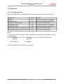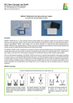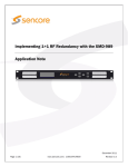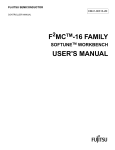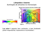
1
Fujitsu Microelectronics Europe
Application Note
MCU-AN-390087-E-V10
F²MC-16LX FAMILY
16-BIT MICROCONTROLLER
ALL SERIES
FLASH PROGRAMMER
YOKOGAWA AF220/221
APPLICATION NOTE
FLASH PROGRAMMER YOKOGAWA AF220/221
Revision History
1 Revision History
Date
23.04.2003
Issue
V1.0, HW, First Release
This document contains 24 pages.
MCU-AN-390087-E-V10
-2-
© Fujitsu Microelectronics Europe GmbH
FLASH PROGRAMMER YOKOGAWA AF220/221
Warranty and Disclaimer
2 Warranty and Disclaimer
To the maximum extent permitted by applicable law, Fujitsu Microelectronics Europe GmbH restricts
its warranties and its liability for all products delivered free of charge (eg. software include or
header files, application examples, target boards, evaluation boards, engineering samples of IC’s
etc.), its performance and any consequential damages, on the use of the Product in accordance
with (i) the terms of the License Agreement and the Sale and Purchase Agreement under which
agreements the Product has been delivered, (ii) the technical descriptions and (iii) all
accompanying written materials. In addition, to the maximum extent permitted by applicable law,
Fujitsu Microelectronics Europe GmbH disclaims all warranties and liabilities for the performance
of the Product and any consequential damages in cases of unauthorised decompiling and/or
reverse engineering and/or disassembling. Note, all these products are intended and must
only be used in an evaluation laboratory environment.
1.
Fujitsu Microelectronics Europe GmbH warrants that the Product will perform substantially in
accordance with the accompanying written materials for a period of 90 days form the date of
receipt by the customer. Concerning the hardware components of the Product, Fujitsu
Microelectronics Europe GmbH warrants that the Product will be free from defects in material
and workmanship under use and service as specified in the accompanying written materials
for a duration of 1 year from the date of receipt by the customer.
2.
Should a Product turn out to be defect, Fujitsu Microelectronics Europe GmbH´s entire liability
and the customer´s exclusive remedy shall be, at Fujitsu Microelectronics Europe GmbH´s
sole discretion, either return of the purchase price and the license fee, or replacement of the
Product or parts thereof, if the Product is returned to Fujitsu Microelectronics Europe GmbH in
original packing and without further defects resulting from the customer´s use or the transport.
However, this warranty is excluded if the defect has resulted from an accident not attributable
to Fujitsu Microelectronics Europe GmbH, or abuse or misapplication attributable to the
customer or any other third party not relating to Fujitsu Microelectronics Europe GmbH.
3.
To the maximum extent permitted by applicable law Fujitsu Microelectronics Europe GmbH
disclaims all other warranties, whether expressed or implied, in particular, but not limited to,
warranties of merchantability and fitness for a particular purpose for which the Product is not
designated.
4.
To the maximum extent permitted by applicable law, Fujitsu Microelectronics Europe GmbH´s
and its suppliers´ liability is restricted to intention and gross negligence.
NO LIABILITY FOR CONSEQUENTIAL DAMAGES
To the maximum extent permitted by applicable law, in no event shall Fujitsu
Microelectronics Europe GmbH and its suppliers be liable for any damages whatsoever
(including but without limitation, consequential and/or indirect damages for personal
injury, assets of substantial value, loss of profits, interruption of business operation,
loss of information, or any other monetary or pecuniary loss) arising from the use of
the Product.
Should one of the above stipulations be or become invalid and/or unenforceable, the remaining
stipulations shall stay in full effect
© Fujitsu Microelectronics Europe GmbH
-3-
MCU-AN-390087-E-V10
FLASH PROGRAMMER YOKOGAWA AF220/221
Contents
3 Contents
1 REVISION HISTORY ....................................................................................................... 2
2 WARRANTY AND DISCLAIMER..................................................................................... 3
3 CONTENTS...................................................................................................................... 4
4 INTRODUCTION.............................................................................................................. 6
4.1
Programmer overview ............................................................................................. 6
4.2
System overview ..................................................................................................... 7
4.3
Serial Interface Cable.............................................................................................. 8
4.3.1
AZ221........................................................................................................ 8
4.3.2
AZ222........................................................................................................ 8
4.4
Target Probe ........................................................................................................... 9
4.5
External Key Entry Interface Cable AZ223 ............................................................ 10
4.6
Pass/Error Adapter AZ266 .................................................................................... 11
5 HARDWARE SET-UP .................................................................................................... 12
5.1
Hardware Configuration......................................................................................... 12
5.1.1
Changing the MCU series........................................................................ 12
5.1.2
Connection to the Target Board ............................................................... 13
6 STAND-ALONE OPERATION ....................................................................................... 14
7 SOFTWARE – REMOTE CONTROLLER AZ290........................................................... 15
7.1
Parameter Load..................................................................................................... 15
7.2
File transfer to PC-card ......................................................................................... 15
7.3
Basic Operation..................................................................................................... 16
7.3.1
File Operation .......................................................................................... 16
7.3.2
Device Function ....................................................................................... 17
8 SOFTWARE – REMOTE CONTROLLER LIBRARY AZ291 .......................................... 18
9 EXTERNAL KEY ENTRY INTERFACE AZ233 .............................................................. 19
10 PASS/ERROR ADAPTER AZ266 .................................................................................. 20
11 PART LIST..................................................................................................................... 21
12 CONTACT ADDRESSES............................................................................................... 22
12.1 Hitex Development Tools GmbH ........................................................................... 22
12.2 AK Elektronik Vertriebs GmbH .............................................................................. 22
12.3 Ashling Microsystems LTD. ................................................................................... 22
12.4 Yokogawa Digital Computer Corporation............................................................... 22
MCU-AN-390087-E-V10
-4-
© Fujitsu Microelectronics Europe GmbH
FLASH PROGRAMMER YOKOGAWA AF220/221
Contents
13 APPENDIX ..................................................................................................................... 23
13.1 Time Measurement ............................................................................................... 23
14 REMARKS ..................................................................................................................... 24
© Fujitsu Microelectronics Europe GmbH
-5-
MCU-AN-390087-E-V10
FLASH PROGRAMMER YOKOGAWA AF220/221
Introduction
4 Introduction
This application note describes the set up and using of the third party Flash-Programmer
“Yokogawa AF220/AF221”.
The programmer allows in-circuit programming of Fujitsu microcontrollers using the serialsynchronous interface.
The Yokogawa AF220/AF221 can be adapted to different target controller types by changing
the control-module (PC-card). With the FF201 module near all Fujitsu microcontrollers
of the 16LX-series can be programmed. The FF205 module supports the MB91F150family (32-Bit), the FF206 module has to be used together with MB91F360-family (32Bit).
It can be used as stand-alone system as well as a PC-controlled programmer using the
RS-232C or the Ethernet interface.
The optional software package AZ290 allows to program remotely control application
software created at customers' sites.
User information and system settings can be stored on the PC-card.
4.1
Programmer overview
Figure 1.1 shows the YOKOGAWA Flash-Programmer AF220 and its most important
operating elements.
Figure 1-1: Aspect of the AF220 Flash-Programmer
MCU-AN-390087-E-V10
-6-
© Fujitsu Microelectronics Europe GmbH
FLASH PROGRAMMER YOKOGAWA AF220/221
Introduction
4.2
System overview
A typical system environment is depicted in the figures 1-2 to 1-4. Depending on the
operation mode, the programmer can be used as stand-alone programmer or it can be
connected to a PC via RS-232C or Ethernet interface.
When using the programmer as stand-alone system then
the following components have to be ordered
separately:
•
Flash Programmer AF220/221
•
Control Module FF201 for Fujitsu 16LX-series
•
Interface cable AZ210 or AZ211 or AZ212
(see chapter “Target Probe” below)
Figure 1-2: Stand-alone Programmer
In case that the programmer wants to be controlled by a PC then additionally the
•
Remote Controller Software Package AZ290 (can be download from homepage) and
•
RS-232C cable AZ221/AZ222 or twisted Pair Ethernet cable
have to be ordered, too
Figure 1-3: PC connection via RS-232C
Figure 1-4: PC connection via Ethernet
If an own software front-end wants to be development then the library-package AZ291 has
to be ordered additionally.
© Fujitsu Microelectronics Europe GmbH
-7-
MCU-AN-390087-E-V10
FLASH PROGRAMMER YOKOGAWA AF220/221
Introduction
4.3
Serial Interface Cable
Two serial interface cables are available.
4.3.1 AZ221
If the COM-port of the host PC uses a 9-pin D-Sub connector then interface cable AZ221
has to be used.
Figure 1-5: Serial interface cable AZ221
4.3.2 AZ222
In case, that the COM-port of the host PC uses a 25-pin D-Sub connector, the interface
cable AZ222 has to be used.
Figure 1-6: Serial interface cable AZ222
MCU-AN-390087-E-V10
-8-
© Fujitsu Microelectronics Europe GmbH
FLASH PROGRAMMER YOKOGAWA AF220/221
Introduction
4.4
Target Probe
The AF220/221 Flash Programmer uses a rare connector for connection to the target board:
DX31A-28P/DX-28-CV from Hirose Electric (www.hirose.com)
Figure 1-8: Pin Layout of Target Probe
Connector viewed from cable side
Figure 1-7: Pin Layout of
Target Probe Connector
Yokogawa offers optional three types of Probe Cables (Interface Cable). Depending on the
target board a cable with connector on both sides, with test clip on one side or a
simple cable has to be ordered:
Figure 1-9: Interface Cable AZ210
Figure 1-10: Interface Cable
AZ211
AF220 -
AZ210 / AZ212
Signal Name
TRXD
Pin No.
27
Figure 1-11: Interface Cable AZ212
AZ211
Pin No.
1
Fujitsu-Name
color
brown
*1
SOTx
*1
TTXD
13
2
red
SINx
TCK
6
12
white & red
SCKx
TAUX
23
9
white
P00
*2
P01
*2
-
-
*1
-
-
TMODE
12
4
yellow
MD0
TAUX4
20
11
white & brown
MD1
TAUX3
19
13
white & orange
MD2
/TRES
5
14
white / yellow
/RST
/TICS
10
8
grey
TVCC
2
20
light blue
Vcc
VCC
3
18
white & grey
Vcc
GND
1,7,8, 14, 15, 21, 22, 28
soldered on PCB
(black)
GND
optional
*3
Table 1-1: Signal assignment of interface cable
*1
The used serial interface depends on the microcontroller series.
*2
Instead of P00, P01 other port-pins may be used
(See to Application-Note AN-MCU-390031-E-xx)
*3
The programmer signals (SINx, SOTx, SCKx, P00, P01, \RST) may conflict with the usersystem while programming. The signal /TICS can be used to disconnect the user circuit but additional three-state
drivers have to be used. Refer to the chapter “Examples of serial programming connection” of the MCU
hardwaremanual.
© Fujitsu Microelectronics Europe GmbH
-9-
MCU-AN-390087-E-V10
FLASH PROGRAMMER YOKOGAWA AF220/221
Introduction
4.5
External Key Entry Interface Cable AZ223
Optional two buttons can be connected externally to EXT.KEY in order to start a command
sequence (see chapter 9).
Figure 1-12: Pin Layout of Connector EXT.KEY
Pin 2
OAK1
Pin 7
Figure 1-13: Connection of external key OAK1
Pin 3
OAK2
Pin 8
Figure 1-14: Connection of external key OAK2
Pin 1
Reset
Pin 6
Figure 1-15: Connection of external reset key
MCU-AN-390087-E-V10
- 10 -
© Fujitsu Microelectronics Europe GmbH
FLASH PROGRAMMER YOKOGAWA AF220/221
Introduction
4.6
Pass/Error Adapter AZ266
This optional adapter uses the signal output from EXT.KEY to give the result of programming
(PASS / ERROR). It can be used to drive lamps or buzzer in e.g. a manufacture line.
Figure 1-16: Pass/Error Adapter AZ266
Pin
1
2
5
6
9
10
13
14
15
17
18
19
20
Signal Name
RES+
RESOAK1+
OAK1OAK2+
OAK2VCC
VCC
/User clear
/PASS
/ERROR
GND
GND
Explanation
Reset Key
One Action Key 1
One Action Key 2
5V, max. 100mA
User clear input (low active)
Pass signal (low active, open collector: VOH=20V, IOL=40mA)
Error signal (low active, open collector: VOH=20V, IOL=40mA)
GND
Table 1-2: Pinout of Pass/Error Adapter AZ266
© Fujitsu Microelectronics Europe GmbH
- 11 -
MCU-AN-390087-E-V10
FLASH PROGRAMMER YOKOGAWA AF220/221
Hardware Set-up
5 Hardware Set-up
This chapter describes how to set up the programmer
5.1
Hardware Configuration
The right PC-card (for Fujitsu 16LX-series: FF201) has to be inserted in the card slot of the
programmer. Of course, the power connection with the external power-adapter and the
connection to the target board via the interface cable have to be done, too.
After switching on the power supply, an internal system-check is done and the used control
module name is displayed.
In case that another microcontroller wants to be used, another Micom Pack has to be used.
5.1.1 Changing the MCU series
In order to change the microcontroller type the latest Micom Pack including the module
parameter file (*.prm) and write control program (*.BTP), means bootloader-kernel, has to be
downloaded from http://www.ydc.co.jp/micom/product/downloadE.htm.
The *.BTP file is like a bootloader-kernel and is always related to a special microcontroller
series.
1. Download latest Micom Pack regarding to your microcontroller-series.
2. Remove PC-card from Yokogawa Programmer.
3.
Insert PC-card to Personal Computer with an enabled PC-card slot.
Note:
In order to enable access to the PC-card the PC-card driver of Windows have to be installed on your PC.
Add the following lines to the config.sys in order to find the PC-card as a drive within the Widows-Explorer:
device=c:\windows\system\csmapper.sys
device=c:\windows\system\carddrv.exe /slot=2
4. Copy the write control program (*.BTP) to PC-card.
5. Remove PC-card from Personal Computer.
6. Insert PC-card to Yokogawa Programmer.
If no PC with PC-card slot is available then the BTP-file can be exchanged using the Remote
software package AZ290 (see chapter 7):
The old BTP-file has to be erased by the command File Purge[FUNC] + F 3 in the tab BasicOperation. Afterwards the new BTP-file can be copied by using the function “Bundle-File:
File Copy from HD to DOS area” from the tab File-Transfer.
Note:
Only one write control program (*.BTP) is allowed to be stored on the PC-card!
In case that more than one BTP-file is located on the PC-card the programming might fail!
MCU-AN-390087-E-V10
- 12 -
© Fujitsu Microelectronics Europe GmbH
FLASH PROGRAMMER YOKOGAWA AF220/221
Hardware Set-up
5.1.2 Connection to the Target Board
All devices of the Fujitsu 16LX-series use at least eight signal lines for serial programming:
•
SINx, SOTx and SCKx
for serial communication *1
•
MD0, MD2, P00, P01
for Mode-setting *2
•
RST
for Reset
*1
The used serial interface depends on the microcontroller series.
*2
Instead of P00, P01 other port-pins may be used
Please refer to the AN-MCU-390031-E-vxx Programming Flash MCUs.
Depending on the used interface cable the corresponding pin connection according to Table
1-1 has to be used.
Figure 2-17 shows a typical connection between the Yokogawa Flash-Programmer and the
target system with a Fujitsu 16LX-microcontroller.
Please refer to the Flash-Programmer manual or the hardware manual of the related
microcontroller (chapter “Examples of serial programming connection”) in order to get more
detailed information.
+
VCC
+
+
+
+
+
+
3 (18 white&grey)
Vcc
max 100mA
Yokogawa
Flash-Programmer
AF220/221
TVCC
2 (20 lightblue)
P01
TAUX
23 (9 white)
P00
TMODE
12 (4 yellow)
MD0
Fujitsu
TAUX4
20 (11 white&brown)
MD1
Microcontroller
TAUX3
19 (13 white&orange)
MD2
/TRES
5 (14 white&yellow)
/RST
TRXD
27 (1 brown)
SOTx
TTXD
13 (2 red)
TCK
6 (12 white&red)
GND
16LX
(MB90Fxxx)
SINx
SCKx
1,14,15,28 (black, directly soldered on PCB)
GNDx
Note: 1) All pin (number/colours) in brackets are for probe
AZ211 2) All resistors are 10kOhm
Figure 2-17: Example of connecting with Fujitsu target system
Note:
For minimum configuration at least the signals GND(GND), TRXD(SOTx), TTXD(SINx),
TCK(SCKx), /TRES(/RST) and TVCC(VCC) have to be connected. The other MCU signals
can be set static to their levels: MD0=P00=GND, MD1=MD2=P01=Vcc while programming.
© Fujitsu Microelectronics Europe GmbH
- 13 -
MCU-AN-390087-E-V10
FLASH PROGRAMMER YOKOGAWA AF220/221
Stand-alone operation
6 Stand-alone operation
This chapter describes the Yokogawa Flash-Programmer in stand-alone mode
The Yokogawa Flash-programmer can be used as stand-alone programmer. In this case, the
programmer can be controlled by the integrated keypad.
The basic functions are listed below.
Note that an explicit connect-command does not exist.
Function
Key-code
Load HEX-file
Blank Check
Erase (including blank-check)
Program
Read Check (Verify)
Automatic (Erase, Program, Verify)
Save HEX-file
[FUNC] F 1 = / > [SET] [FUNC] [SET]
Purge file
[FUNC] F 3 = / > [SET] [FUNC] [SET] [SET]
[DEV] 9 [SET] [DEV] [SET]
[DEV] C [SET] [DEV] [SET]
[DEV] D [SET] [DEV] [SET]
[DEV] E [SET] [DEV] [SET]
[DEV] F [SET] [DEV] [SET]
[FUNC] F 2 = / > [SET] [FUNC] [SET]
Table 3-3: Basic Functions in stand-alone mode
For further and more specific functions, please refer to the Instruction Manual of the
Yokogawa Flash-programmer.
MCU-AN-390087-E-V10
- 14 -
© Fujitsu Microelectronics Europe GmbH
FLASH PROGRAMMER YOKOGAWA AF220/221
Software – Remote Controller AZ290
7 Software – Remote Controller AZ290
This chapter describes how to remote control the Yokogawa Flash-Programmer by a PC
The Remote Software Package AZ290 allows to set-up and to control the Flash-Programmer
by a PC.
Connect the Flash programmer AF220/221 via RS-232C or Ethernet to the PC. If the
Ethernet wants to be used, refer to the user-manual how to set-up the IP-address.
Start the Remote-Software AZ290. The software should automatically find the programmer.
7.1
Parameter Load
The parameter file contents the microcontroller-related information like e.g. Flash-Memory
size.
In order to load a new microcontroller series, open the tab “File Transfer” and select
“Parameter Load from HD”.
After the file is successfully loaded, the MCU-type is shown on the programmers LC-display.
7.2
File transfer to PC-card
Keep in mind that the related bootloader-kernel (write control program, *.BTP) has to be
copied manually to the PC-card. This can be done by the button “File copy from HD to DOS
area” in the group “Bundle File”. See chapter 5.1.1 for more details.
© Fujitsu Microelectronics Europe GmbH
- 15 -
MCU-AN-390087-E-V10
FLASH PROGRAMMER YOKOGAWA AF220/221
Software – Remote Controller AZ290
7.3
Basic Operation
The basic functions for file handling (load, save, purge, etc.) on the PC-card and for
programming a device are available in the tab “Basic Operations”.
7.3.1 File Operation
Within the Group “File Operation” basic functions for handling the data files on the PC-card
can be found:
FILE LOAD
copies data from PC-card into the buffer
FILE SAVE
stores data from the buffer to the PC-card
FILE PURGE
deletes a specific file
Figure 4-18: File operation on PC-card
Please take care that the file handling is a little bit windows unusual:
Whether files can be marked in the file list, this will not be kept after a file operation is
selected. Within the file operation the filename has to be picked by the buttons + and -.
MCU-AN-390087-E-V10
- 16 -
© Fujitsu Microelectronics Europe GmbH
FLASH PROGRAMMER YOKOGAWA AF220/221
Software – Remote Controller AZ290
7.3.2 Device Function
The basic functions for programming a device are available in the tab “Basic Operations”:
ERASE
erases the flash-memory and performs blank check
BLANK
checks whether the memory is cleared
PROGRAM
programs the flash-memory with the data of the buffer;
after programming a verify (=read) is done
READ means Read-check and verifies the flash-memory with the buffer
COPY readouts the flash-memory into the buffer
E.P.R performs automatically: ERASE – PROGRAM – READ (verify)
Figure 4-19: Basic programmer operations
ERASE
Program Flash
Automatic
© Fujitsu Microelectronics Europe GmbH
- 17 -
Blank Check
Verify
Readout Flash
MCU-AN-390087-E-V10
FLASH PROGRAMMER YOKOGAWA AF220/221
Software – Remote Controller Library AZ291
8 Software – Remote Controller Library AZ291
This chapter lists the software library functions for programming own applications
A software package AZ291 is available to program own front-end applications.
The library functions are based on Visual Basic 5.0.
Overview of Library Functions included in AZ291:
BUFFER_CLEAR ()
BLOCK_STORE ()
CHECK_YSM ()
REQUEST_SUM ()
FILE_LOAD ()
FILE_PURGE ()
FILE_ALL_PURGE ()
DOSFILE_DOWNLOAD ()
DOSFILE_UPLOAD ()
FILE_DOWNLOAD ()
FILE_UPLOAD ()
PARAMETER_DOWNLOAD ()
PARAMETER _UPLOAD ()
DEVICE_ERASE ()
PROGRAM ()
EPR ()
READ ()
COPY ()
BLANK ()
SET_RS232C_PARAMETER ()
COM_CHECK ()
DISPLAY_TYPE ()
STATUS ()
CONTROL_MODULE_DOWNLOAD ()
For more details, please refer to the User Manual of AZ291
MCU-AN-390087-E-V10
- 18 -
© Fujitsu Microelectronics Europe GmbH
FLASH PROGRAMMER YOKOGAWA AF220/221
External Key Entry Interface AZ233
9 External Key Entry Interface AZ233
This chapter describes how to use two external buttons to control the Flash-Programmer
In order to integrate the Yokogawa Flash-Programmer in an automatic assembly line, two
external switch-buttons or relays connected to EXT.KEX can be used to start a command
sequencer.
A command sequence file (*.CSB) is used to define the function.
In case that the signal lines OAK1+ and OAK1- respectively OAK2+ and OAK2- are shortcut
the command sequence LK1 respectively LK2, stored in the CSB-file, is started.
Alternatively two buttons of the keypad can be used, see
This text file consists of two lines. It can be easily edited, e.g.:
my.csb:
LK1,04,E,B,P,R;remark: Erase/BlankCheck/Program/Verify [CRLF]
LK2,01,P;remark: only Program without erasing the chip [CRLF]
Number of commands
Command Sequence
E
ERASE
P
Program
B
Blank Check
R
Read Check (Verify)
Note: A maximum number of 16 commands can be executed within one sequence.
EXT.KEY
Figure 6-20: One Action key
© Fujitsu Microelectronics Europe GmbH
- 19 -
MCU-AN-390087-E-V10
FLASH PROGRAMMER YOKOGAWA AF220/221
Pass/Error Adapter AZ266
10 Pass/Error Adapter AZ266
This chapter describes how to output the programming result
For extended functionality within an assembly line, the Pass/Error adapter AZ266 (see
chapter 4.6) may be helpful to output the result of programming.
By this adapter, communication with a SPS-interface is possible.
OAK1
Yokogawa
Flash-Programmer
AF220
Ext.KEY
PASS/ERROR
Start Programming
OAK2
Adapter
AZ266
PASS
ERROR
Figure 7-21: Pass/Error adapter AZ266
Function
ERASE
BLANK CHECK
PROGRAM
READ
E.P.R.
PASS
Chip was erased successfully
Chip is empty
Program ended successfully
Verify okay
Automatic programming
ended successfully
ERROR
Chip erase failed
Chip is not empty
Programming failed
Verify failed
Automatic programming failed
Table 7-4: Function results
MCU-AN-390087-E-V10
- 20 -
© Fujitsu Microelectronics Europe GmbH
FLASH PROGRAMMER YOKOGAWA AF220/221
Part List
11 Part List
AF221
Main Unit of Flash microcomputer Programmer
FF201
FF205
FF206
Control Module for Fujitsu 16LX microcontroller
Control Module for Fujitsu microcontroller 91F154, 91F155
Control Module for Fujitsu microcontroller 91F362GA (asynchronous mode)
AZ221
AZ222
PC cable (D-SUB 9pin – D-SUB 9pin)
PC cable (D-SUB 9pin – D-SUB 25pin)
AZ210
AZ211
AZ212
Probe cable with 2x Hirose-connector
Probe cable with Test-clips
Probe cable with open end
AZ223
AZ266
EXT.KEY interface cable
PASS/ERROR Adapter
AZ290
AZ291
Remote Control Software (can be downloaded from YDC homepage)
Remote Control Software including Library functions to build own applications
© Fujitsu Microelectronics Europe GmbH
- 21 -
MCU-AN-390087-E-V10
FLASH PROGRAMMER YOKOGAWA AF220/221
Contact Addresses
12 Contact Addresses
12.1 Hitex Development Tools GmbH
Mr. Roland Helbig
Director Marketing & Sales
Greschbachstr. 12
76229 Karlsruhe
GERMANY
Phone: +49-(0)721 9628 - 134
Fax:
+49-(0)721 9628 - 149
E-mail: [email protected]
http://www.hitex.de
12.2 AK Elektronik Vertriebs GmbH
Mr. Gerhard Neumann
Eichenstrasse 11
86567 Hilgertshausen
Germany
Phone: +49-(0)8250 999515
Fax:
+49-(0)8250 999520
Email: [email protected]
http://www.ak-elektronik.de
12.3 Ashling Microsystems LTD.
Mr. Ian Harry
Intec2, Wade Road,
Basingstoke, Hants, RG24 8NE,
United Kingdom
Phone: +44-(0)1256-811998
Fax:
+44-(0)1256-811761
E-mail: [email protected]
http://www.ashling.com/
12.4 Yokogawa Digital Computer Corporation
Teruki Kawano
Intec2, Wade Road,
Basingstoke, Hants, RG24 8NE, UK
Phone: +44-(0)1256-811998,
FAX:
+44-(0)1256-811761
E-mail : [email protected]
http://www.ydc.co.jp/micom/index_E.htm
MCU-AN-390087-E-V10
- 22 -
© Fujitsu Microelectronics Europe GmbH
FLASH PROGRAMMER YOKOGAWA AF220/221
Appendix
13 Appendix
13.1 Time Measurement
Based on a MB90F394 with 384KByte Flash the following execution time was measured:
Command
Time
ERASE
BLANK CHECK
ERASE (incl. BlankCheck)
PROGRAM (128K)*1
PROGRAM (384K)
PROGRAM (128K) (incl. Read-Check)
PROGRAM (384K) (incl. Read-Check)
9 sec
4 sec
11 sec
5 sec
14 sec
7 sec
18 sec
Remark
called by One Action key (CSB-file)
called by One Action key (CSB-file)
[DEV] C [SET] [DEV] [SET]
called by One Action key (CSB-file)
called by One Action key (CSB-file)
[DEV] D [SET] [DEV] [SET]
[DEV] D [SET] [DEV] [SET]
Note *1
In case that not the total memory space is used the start-address and end-address have to
be set manually:
[FUNC] 0 FE0000 > wait some seconds FFFFFF > wait some seconds [SET] [FUNC] [SET]
Start-address
End-address
For further details see AF220 Instruction manual.
© Fujitsu Microelectronics Europe GmbH
- 23 -
MCU-AN-390087-E-V10
FLASH PROGRAMMER YOKOGAWA AF220/221
Remarks
14 Remarks
MCU-AN-390087-E-V10
- 24 -
© Fujitsu Microelectronics Europe GmbH