1
Mellanox WinOF VPI User Manual
Rev 4.70
www.mellanox.com
Rev 4.70
2
Mellanox Technologies
Document Number: MLNX-15-3280
Rev 4.70
Table of Contents
Revision History . . . . . . . . . . . . . . . . . . . . . . . . . . . . . . . . . . . . . . . . . . . . . . . . . . . . . . . . . . . 9
About this Manual . . . . . . . . . . . . . . . . . . . . . . . . . . . . . . . . . . . . . . . . . . . . . . . . . . . . . . . . 13
Scope . . . . . . . . . . . . . . . . . . . . . . . . . . . . . . . . . . . . . . . . . . . . . . . . . . . . . . . . . . . . . . .13
Intended Audience . . . . . . . . . . . . . . . . . . . . . . . . . . . . . . . . . . . . . . . . . . . . . . . . . . . . .13
Documentation Conventions . . . . . . . . . . . . . . . . . . . . . . . . . . . . . . . . . . . . . . . . . . . . .13
Common Abbreviations and Acronyms . . . . . . . . . . . . . . . . . . . . . . . . . . . . . . . . . . . . .14
Related Documents . . . . . . . . . . . . . . . . . . . . . . . . . . . . . . . . . . . . . . . . . . . . . . . . . . . .15
Chapter 1 Introduction . . . . . . . . . . . . . . . . . . . . . . . . . . . . . . . . . . . . . . . . . . . . . . . . . . . 16
1.1
1.2
1.3
Hardware and Software Requirements . . . . . . . . . . . . . . . . . . . . . . . . . . . . . . . . 16
Supplied Packages . . . . . . . . . . . . . . . . . . . . . . . . . . . . . . . . . . . . . . . . . . . . . . . . 16
WinOF Set of Documentation . . . . . . . . . . . . . . . . . . . . . . . . . . . . . . . . . . . . . . . 16
Chapter 2 Downloading Mellanox WinOF Driver . . . . . . . . . . . . . . . . . . . . . . . . . . . . . 17
Chapter 3 Extracting Files Without Running Installation. . . . . . . . . . . . . . . . . . . . . . . 18
Chapter 4 Installing Mellanox WinOF Driver . . . . . . . . . . . . . . . . . . . . . . . . . . . . . . . . 20
4.1
4.2
4.3
Attended Installation . . . . . . . . . . . . . . . . . . . . . . . . . . . . . . . . . . . . . . . . . . . . . . 20
Unattended Installation . . . . . . . . . . . . . . . . . . . . . . . . . . . . . . . . . . . . . . . . . . . . 25
Installation Results. . . . . . . . . . . . . . . . . . . . . . . . . . . . . . . . . . . . . . . . . . . . . . . . 25
Chapter 5 Uninstalling Mellanox WinOF Driver . . . . . . . . . . . . . . . . . . . . . . . . . . . . . . 27
5.1
5.2
5.3
Attended Uninstall . . . . . . . . . . . . . . . . . . . . . . . . . . . . . . . . . . . . . . . . . . . . . . . . 27
Unattended Uninstall . . . . . . . . . . . . . . . . . . . . . . . . . . . . . . . . . . . . . . . . . . . . . . 27
Firmware Upgrade . . . . . . . . . . . . . . . . . . . . . . . . . . . . . . . . . . . . . . . . . . . . . . . . 27
Chapter 6 Upgrading Mellanox WinOF Driver . . . . . . . . . . . . . . . . . . . . . . . . . . . . . . . 28
Chapter 7 Advanced Driver Configuration. . . . . . . . . . . . . . . . . . . . . . . . . . . . . . . . . . . 29
7.1
7.2
Assigning Port IP After Installation. . . . . . . . . . . . . . . . . . . . . . . . . . . . . . . . . . . 29
Configuring the InfiniBand Driver . . . . . . . . . . . . . . . . . . . . . . . . . . . . . . . . . . . 31
7.2.1 Modifying IPoIB Configuration . . . . . . . . . . . . . . . . . . . . . . . . . . . . . . . . . . . . . . 31
7.2.2 Displaying Adapter Related Information . . . . . . . . . . . . . . . . . . . . . . . . . . . . . . . 32
7.3
7.4
Configuring the Ethernet Driver . . . . . . . . . . . . . . . . . . . . . . . . . . . . . . . . . . . . . 33
Configuring Quality of Service (QoS). . . . . . . . . . . . . . . . . . . . . . . . . . . . . . . . . 34
Chapter 8 Driver Features . . . . . . . . . . . . . . . . . . . . . . . . . . . . . . . . . . . . . . . . . . . . . . . . 36
8.1
8.2
8.3
8.4
Hyper-V with VMQ. . . . . . . . . . . . . . . . . . . . . . . . . . . . . . . . . . . . . . . . . . . . . . .
Header Data Split. . . . . . . . . . . . . . . . . . . . . . . . . . . . . . . . . . . . . . . . . . . . . . . . .
Receive Side Scaling (RSS). . . . . . . . . . . . . . . . . . . . . . . . . . . . . . . . . . . . . . . . .
Port Configuration . . . . . . . . . . . . . . . . . . . . . . . . . . . . . . . . . . . . . . . . . . . . . . . .
36
37
37
38
8.4.1 Auto Sensing . . . . . . . . . . . . . . . . . . . . . . . . . . . . . . . . . . . . . . . . . . . . . . . . . . . . . 38
8.4.2 Port Protocol Configuration . . . . . . . . . . . . . . . . . . . . . . . . . . . . . . . . . . . . . . . . . 38
8.5
Load Balancing, Fail-Over (LBFO) and VLAN . . . . . . . . . . . . . . . . . . . . . . . . . 39
8.5.1 Adapter Teaming. . . . . . . . . . . . . . . . . . . . . . . . . . . . . . . . . . . . . . . . . . . . . . . . . . 39
8.5.2 Creating a Load Balancing and Fail-Over (LBFO) Bundle . . . . . . . . . . . . . . . . . 40
Mellanox Technologies
3
Rev 4.70
8.5.3 Creating a Port VLAN in Windows 2008 R2 . . . . . . . . . . . . . . . . . . . . . . . . . . . . 43
8.5.4 Removing a Port VLAN in Windows 2008 R2 . . . . . . . . . . . . . . . . . . . . . . . . . . 46
8.5.5 Configuring a Port to Work with VLAN in Windows 2012 and Above . . . . . . . 47
8.6
8.7
Ports TX Arbitration . . . . . . . . . . . . . . . . . . . . . . . . . . . . . . . . . . . . . . . . . . . . . . 47
RDMA over Converged Ethernet (RoCE). . . . . . . . . . . . . . . . . . . . . . . . . . . . . . 48
8.7.1
8.7.2
8.7.3
8.7.4
8.7.5
8.7.6
8.8
48
49
50
50
51
51
Network Virtualization using Generic Routing Encapsulation . . . . . . . . . . . . . . 52
8.8.1
8.8.2
8.8.3
8.8.4
8.9
RoCE Overview . . . . . . . . . . . . . . . . . . . . . . . . . . . . . . . . . . . . . . . . . . . . . . . . . .
RoCE Configuration . . . . . . . . . . . . . . . . . . . . . . . . . . . . . . . . . . . . . . . . . . . . . . .
Configuring SwitchX® Based Switch System . . . . . . . . . . . . . . . . . . . . . . . . . . .
Configuring Arista Switch . . . . . . . . . . . . . . . . . . . . . . . . . . . . . . . . . . . . . . . . . .
Configuring Router (PFC only) . . . . . . . . . . . . . . . . . . . . . . . . . . . . . . . . . . . . . .
Configuring the RoCE Mode . . . . . . . . . . . . . . . . . . . . . . . . . . . . . . . . . . . . . . . .
Enabling/Disabling NVGRE Offloading . . . . . . . . . . . . . . . . . . . . . . . . . . . . . . .
Configuring the NVGRE using PowerShell . . . . . . . . . . . . . . . . . . . . . . . . . . . . .
Verifying the Encapsulation of the Traffic . . . . . . . . . . . . . . . . . . . . . . . . . . . . . .
Removing NVGRE configuration. . . . . . . . . . . . . . . . . . . . . . . . . . . . . . . . . . . . .
53
54
55
55
Differentiated Services Code Point (DSCP) . . . . . . . . . . . . . . . . . . . . . . . . . . . . 55
8.9.1
8.9.2
8.9.3
8.9.4
8.9.5
8.9.6
Setting the DSCP in the IP Header . . . . . . . . . . . . . . . . . . . . . . . . . . . . . . . . . . . .
Configuring Quality of Service for TCP and RDMA Traffic . . . . . . . . . . . . . . . .
Configuring DSCP for TCP Traffic . . . . . . . . . . . . . . . . . . . . . . . . . . . . . . . . . . .
Configuring DSCP for RDMA Traffic . . . . . . . . . . . . . . . . . . . . . . . . . . . . . . . . .
Registry Settings . . . . . . . . . . . . . . . . . . . . . . . . . . . . . . . . . . . . . . . . . . . . . . . . . .
DSCP Sanity Testing. . . . . . . . . . . . . . . . . . . . . . . . . . . . . . . . . . . . . . . . . . . . . . .
56
56
56
56
57
58
8.10 SR-IOV . . . . . . . . . . . . . . . . . . . . . . . . . . . . . . . . . . . . . . . . . . . . . . . . . . . . . . . . 58
8.10.1
8.10.2
8.10.3
8.10.4
8.10.5
System Requirements . . . . . . . . . . . . . . . . . . . . . . . . . . . . . . . . . . . . . . . . . . . . . .
SR-IOV Feature Limitations . . . . . . . . . . . . . . . . . . . . . . . . . . . . . . . . . . . . . . . . .
Configuring SR-IOV Host Machine . . . . . . . . . . . . . . . . . . . . . . . . . . . . . . . . . . .
Configuring Mellanox Network Adapter for SR-IOV . . . . . . . . . . . . . . . . . . . . .
Configuring Virtual Machine Networking . . . . . . . . . . . . . . . . . . . . . . . . . . . . . .
59
59
59
65
68
8.11 Virtual Ethernet Adapter . . . . . . . . . . . . . . . . . . . . . . . . . . . . . . . . . . . . . . . . . . . 72
8.11.1
8.11.2
8.11.3
8.11.4
8.11.5
8.11.6
System Requirements . . . . . . . . . . . . . . . . . . . . . . . . . . . . . . . . . . . . . . . . . . . . . .
VEA Feature Limitations . . . . . . . . . . . . . . . . . . . . . . . . . . . . . . . . . . . . . . . . . . .
Adding a New Virtual Adapter . . . . . . . . . . . . . . . . . . . . . . . . . . . . . . . . . . . . . . .
Removing a Virtual Ethernet Adapter. . . . . . . . . . . . . . . . . . . . . . . . . . . . . . . . . .
Querying the Virtual Ethernet Database . . . . . . . . . . . . . . . . . . . . . . . . . . . . . . . .
Help Message . . . . . . . . . . . . . . . . . . . . . . . . . . . . . . . . . . . . . . . . . . . . . . . . . . . .
72
73
73
73
73
73
8.12 IPoIB SR-IOV over KVM . . . . . . . . . . . . . . . . . . . . . . . . . . . . . . . . . . . . . . . . . . 74
8.13 Lossless TCP . . . . . . . . . . . . . . . . . . . . . . . . . . . . . . . . . . . . . . . . . . . . . . . . . . . . 74
8.13.1
8.13.2
8.13.3
8.13.4
8.13.5
8.13.6
8.13.7
8.13.8
Introduction . . . . . . . . . . . . . . . . . . . . . . . . . . . . . . . . . . . . . . . . . . . . . . . . . . . . . .
Drop Mode . . . . . . . . . . . . . . . . . . . . . . . . . . . . . . . . . . . . . . . . . . . . . . . . . . . . . .
Poll Mode . . . . . . . . . . . . . . . . . . . . . . . . . . . . . . . . . . . . . . . . . . . . . . . . . . . . . . .
Default behavior . . . . . . . . . . . . . . . . . . . . . . . . . . . . . . . . . . . . . . . . . . . . . . . . . .
Known Limitations . . . . . . . . . . . . . . . . . . . . . . . . . . . . . . . . . . . . . . . . . . . . . . . .
System Requirements . . . . . . . . . . . . . . . . . . . . . . . . . . . . . . . . . . . . . . . . . . . . . .
Enabling/Disabling Lossless TCP. . . . . . . . . . . . . . . . . . . . . . . . . . . . . . . . . . . . .
Monitoring Lossless TCP State. . . . . . . . . . . . . . . . . . . . . . . . . . . . . . . . . . . . . . .
74
75
75
75
75
75
75
76
Mellanox Technologies
4
Rev 4.70
Chapter 9 Booting Windows from an iSCSI Target . . . . . . . . . . . . . . . . . . . . . . . . . . . . 77
9.1
Configuring the WDS, DHCP and iSCSI Servers . . . . . . . . . . . . . . . . . . . . . . . . 77
9.1.1 Configuring the WDS Server . . . . . . . . . . . . . . . . . . . . . . . . . . . . . . . . . . . . . . . . 77
9.1.2 Configuring iSCSI Target . . . . . . . . . . . . . . . . . . . . . . . . . . . . . . . . . . . . . . . . . . . 77
9.1.3 Configuring the DHCP Server . . . . . . . . . . . . . . . . . . . . . . . . . . . . . . . . . . . . . . . 77
9.2
9.3
Configuring the Client Machine . . . . . . . . . . . . . . . . . . . . . . . . . . . . . . . . . . . . . 78
Installing iSCSI . . . . . . . . . . . . . . . . . . . . . . . . . . . . . . . . . . . . . . . . . . . . . . . . . . 78
Chapter 10 Deploying Windows Server 2012 and Above with SMB Direct. . . . . . . . . . 80
10.1 Overview . . . . . . . . . . . . . . . . . . . . . . . . . . . . . . . . . . . . . . . . . . . . . . . . . . . . . . . 80
10.2 Hardware and Software Prerequisites . . . . . . . . . . . . . . . . . . . . . . . . . . . . . . . . . 80
10.3 SMB Configuration Verification . . . . . . . . . . . . . . . . . . . . . . . . . . . . . . . . . . . . . 80
10.3.1 Verifying Network Adapter Configuration . . . . . . . . . . . . . . . . . . . . . . . . . . . . . . 80
10.3.2 Verifying SMB Configuration . . . . . . . . . . . . . . . . . . . . . . . . . . . . . . . . . . . . . . . 80
10.3.3 Verifying SMB Connection . . . . . . . . . . . . . . . . . . . . . . . . . . . . . . . . . . . . . . . . . 82
10.4 Verifying SMB Events that Confirm RDMA Connection. . . . . . . . . . . . . . . . . . 82
Chapter 11 Performance Tuning . . . . . . . . . . . . . . . . . . . . . . . . . . . . . . . . . . . . . . . . . . . . 83
11.1 General Performance Optimization and Tuning . . . . . . . . . . . . . . . . . . . . . . . . . 83
11.1.1
11.1.2
11.1.3
11.1.4
11.1.5
11.1.6
Registry Tuning. . . . . . . . . . . . . . . . . . . . . . . . . . . . . . . . . . . . . . . . . . . . . . . . . . .
Enable RSS . . . . . . . . . . . . . . . . . . . . . . . . . . . . . . . . . . . . . . . . . . . . . . . . . . . . . .
Tuning the IPoIB Network Adapter . . . . . . . . . . . . . . . . . . . . . . . . . . . . . . . . . . .
Tuning the Ethernet Network Adapter . . . . . . . . . . . . . . . . . . . . . . . . . . . . . . . . .
SR-IOV Tuning . . . . . . . . . . . . . . . . . . . . . . . . . . . . . . . . . . . . . . . . . . . . . . . . . . .
Improving Live Migration. . . . . . . . . . . . . . . . . . . . . . . . . . . . . . . . . . . . . . . . . . .
83
83
83
84
89
89
11.2 Application Specific Optimization and Tuning . . . . . . . . . . . . . . . . . . . . . . . . . . 89
11.2.1 Ethernet Performance Tuning . . . . . . . . . . . . . . . . . . . . . . . . . . . . . . . . . . . . . . . . 89
11.2.2 IPoIB Performance Tuning . . . . . . . . . . . . . . . . . . . . . . . . . . . . . . . . . . . . . . . . . . 89
11.3 Tunable Performance Parameters . . . . . . . . . . . . . . . . . . . . . . . . . . . . . . . . . . . . 90
11.4 Adapter Proprietary Performance Counters. . . . . . . . . . . . . . . . . . . . . . . . . . . . . 92
11.4.1 Supported Standard Performance Counters . . . . . . . . . . . . . . . . . . . . . . . . . . . . . 93
Chapter 12 OpenSM - Subnet Manager . . . . . . . . . . . . . . . . . . . . . . . . . . . . . . . . . . . . . . 98
Chapter 13 Software Development Kit (SDK) . . . . . . . . . . . . . . . . . . . . . . . . . . . . . . . . . 99
Chapter 14 InfiniBand Fabric Utilities . . . . . . . . . . . . . . . . . . . . . . . . . . . . . . . . . . . . . . 100
14.1 Network Direct Interface . . . . . . . . . . . . . . . . . . . . . . . . . . . . . . . . . . . . . . . . . . 100
14.2 part_man - Virtual IPoIB Port Creation Utility . . . . . . . . . . . . . . . . . . . . . . . . . 100
14.3 InfiniBand Fabric Diagnostic Utilities. . . . . . . . . . . . . . . . . . . . . . . . . . . . . . . . 100
14.3.1
14.3.2
14.3.3
14.3.4
14.3.5
14.3.6
14.3.7
14.3.8
14.3.9
Utilities Usage . . . . . . . . . . . . . . . . . . . . . . . . . . . . . . . . . . . . . . . . . . . . . . . . . . .
ibdiagnet . . . . . . . . . . . . . . . . . . . . . . . . . . . . . . . . . . . . . . . . . . . . . . . . . . . . . . .
ibportstate . . . . . . . . . . . . . . . . . . . . . . . . . . . . . . . . . . . . . . . . . . . . . . . . . . . . . .
ibroute . . . . . . . . . . . . . . . . . . . . . . . . . . . . . . . . . . . . . . . . . . . . . . . . . . . . . . . . .
ibdump. . . . . . . . . . . . . . . . . . . . . . . . . . . . . . . . . . . . . . . . . . . . . . . . . . . . . . . . .
smpquery . . . . . . . . . . . . . . . . . . . . . . . . . . . . . . . . . . . . . . . . . . . . . . . . . . . . . . .
perfquery . . . . . . . . . . . . . . . . . . . . . . . . . . . . . . . . . . . . . . . . . . . . . . . . . . . . . . .
ibping. . . . . . . . . . . . . . . . . . . . . . . . . . . . . . . . . . . . . . . . . . . . . . . . . . . . . . . . . .
ibnetdiscover . . . . . . . . . . . . . . . . . . . . . . . . . . . . . . . . . . . . . . . . . . . . . . . . . . . .
100
102
104
107
109
110
114
117
118
Mellanox Technologies
5
Rev 4.70
14.3.10 ibtracert . . . . . . . . . . . . . . . . . . . . . . . . . . . . . . . . . . . . . . . . . . . . . . . . . . . . . . .
14.3.11 sminfo . . . . . . . . . . . . . . . . . . . . . . . . . . . . . . . . . . . . . . . . . . . . . . . . . . . . . . . .
14.3.12 ibclearerrors . . . . . . . . . . . . . . . . . . . . . . . . . . . . . . . . . . . . . . . . . . . . . . . . . . . .
14.3.13 ibstat. . . . . . . . . . . . . . . . . . . . . . . . . . . . . . . . . . . . . . . . . . . . . . . . . . . . . . . . . .
14.3.14 vstat . . . . . . . . . . . . . . . . . . . . . . . . . . . . . . . . . . . . . . . . . . . . . . . . . . . . . . . . . .
14.3.15 osmtest . . . . . . . . . . . . . . . . . . . . . . . . . . . . . . . . . . . . . . . . . . . . . . . . . . . . . . . .
14.3.16 ibaddr . . . . . . . . . . . . . . . . . . . . . . . . . . . . . . . . . . . . . . . . . . . . . . . . . . . . . . . . .
14.3.17 ibcacheedit . . . . . . . . . . . . . . . . . . . . . . . . . . . . . . . . . . . . . . . . . . . . . . . . . . . . .
14.3.18 iblinkinfo . . . . . . . . . . . . . . . . . . . . . . . . . . . . . . . . . . . . . . . . . . . . . . . . . . . . . .
14.3.19 ibqueryerrors . . . . . . . . . . . . . . . . . . . . . . . . . . . . . . . . . . . . . . . . . . . . . . . . . . .
14.3.20 ibsysstat . . . . . . . . . . . . . . . . . . . . . . . . . . . . . . . . . . . . . . . . . . . . . . . . . . . . . . .
14.3.21 saquery . . . . . . . . . . . . . . . . . . . . . . . . . . . . . . . . . . . . . . . . . . . . . . . . . . . . . . . .
14.3.22 smpdump . . . . . . . . . . . . . . . . . . . . . . . . . . . . . . . . . . . . . . . . . . . . . . . . . . . . . .
122
123
125
125
126
126
129
131
132
133
135
137
139
14.4 InfiniBand Fabric Performance Utilities . . . . . . . . . . . . . . . . . . . . . . . . . . . . . . 141
14.4.1 ib_read_bw . . . . . . . . . . . . . . . . . . . . . . . . . . . . . . . . . . . . . . . . . . . . . . . . . . . . .
14.4.2 ib_read_lat. . . . . . . . . . . . . . . . . . . . . . . . . . . . . . . . . . . . . . . . . . . . . . . . . . . . . .
14.4.3 ib_send_bw . . . . . . . . . . . . . . . . . . . . . . . . . . . . . . . . . . . . . . . . . . . . . . . . . . . . .
14.4.4 ib_send_lat . . . . . . . . . . . . . . . . . . . . . . . . . . . . . . . . . . . . . . . . . . . . . . . . . . . . .
14.4.5 ib_write_bw. . . . . . . . . . . . . . . . . . . . . . . . . . . . . . . . . . . . . . . . . . . . . . . . . . . . .
14.4.6 ib_write_lat . . . . . . . . . . . . . . . . . . . . . . . . . . . . . . . . . . . . . . . . . . . . . . . . . . . . .
14.4.7 ibv_read_bw . . . . . . . . . . . . . . . . . . . . . . . . . . . . . . . . . . . . . . . . . . . . . . . . . . . .
14.4.8 ibv_read_lat. . . . . . . . . . . . . . . . . . . . . . . . . . . . . . . . . . . . . . . . . . . . . . . . . . . . .
14.4.9 ibv_send_bw . . . . . . . . . . . . . . . . . . . . . . . . . . . . . . . . . . . . . . . . . . . . . . . . . . . .
14.4.10 ibv_send_lat. . . . . . . . . . . . . . . . . . . . . . . . . . . . . . . . . . . . . . . . . . . . . . . . . . . .
14.4.11 ibv_write_bw . . . . . . . . . . . . . . . . . . . . . . . . . . . . . . . . . . . . . . . . . . . . . . . . . . .
14.4.12 ibv_write_lat . . . . . . . . . . . . . . . . . . . . . . . . . . . . . . . . . . . . . . . . . . . . . . . . . . .
14.4.13 nd_write_bw . . . . . . . . . . . . . . . . . . . . . . . . . . . . . . . . . . . . . . . . . . . . . . . . . . .
14.4.14 nd_write_lat . . . . . . . . . . . . . . . . . . . . . . . . . . . . . . . . . . . . . . . . . . . . . . . . . . . .
14.4.15 nd_read_bw . . . . . . . . . . . . . . . . . . . . . . . . . . . . . . . . . . . . . . . . . . . . . . . . . . . .
14.4.16 nd_read_lat . . . . . . . . . . . . . . . . . . . . . . . . . . . . . . . . . . . . . . . . . . . . . . . . . . . .
14.4.17 nd_send_bw . . . . . . . . . . . . . . . . . . . . . . . . . . . . . . . . . . . . . . . . . . . . . . . . . . . .
14.4.18 nd_send_lat . . . . . . . . . . . . . . . . . . . . . . . . . . . . . . . . . . . . . . . . . . . . . . . . . . . .
14.4.19 NTttcp . . . . . . . . . . . . . . . . . . . . . . . . . . . . . . . . . . . . . . . . . . . . . . . . . . . . . . . .
141
142
143
143
144
145
146
148
149
150
152
153
155
155
156
157
158
159
160
Chapter 15 Troubleshooting . . . . . . . . . . . . . . . . . . . . . . . . . . . . . . . . . . . . . . . . . . . . . . . 162
15.1
15.2
15.3
15.4
15.5
InfiniBand Troubleshooting. . . . . . . . . . . . . . . . . . . . . . . . . . . . . . . . . . . . . . . .
Ethernet Troubleshooting . . . . . . . . . . . . . . . . . . . . . . . . . . . . . . . . . . . . . . . . .
Performance Troubleshooting . . . . . . . . . . . . . . . . . . . . . . . . . . . . . . . . . . . . . .
General Troubleshooting . . . . . . . . . . . . . . . . . . . . . . . . . . . . . . . . . . . . . . . . . .
Installation Error Codes and Troubleshooting. . . . . . . . . . . . . . . . . . . . . . . . . .
162
162
164
166
167
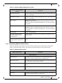
15.5.1 Setup Return Codes. . . . . . . . . . . . . . . . . . . . . . . . . . . . . . . . . . . . . . . . . . . . . . . 167
15.5.2 Firmware Burning Warning Codes . . . . . . . . . . . . . . . . . . . . . . . . . . . . . . . . . . . 167
15.5.3 Restore Configuration Warnings. . . . . . . . . . . . . . . . . . . . . . . . . . . . . . . . . . . . . 167
Mellanox Technologies
6
Rev 4.70
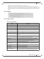
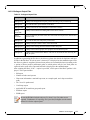
List of Tables
Table 1
Table 2
Table 3
Table 4
Table 5
Table 6
Table 7
Table 8
Table 9
Table 10
Table 11
Table 12
Table 13
Table 14
Table 15
Table 16
Table 17
Table 18
Table 19
Table 20
Table 21
Table 22
Table 23
Table 24
Table 25
Table 26
Table 27
Table 28
Table 29
Table 30
Table 31
Table 32
Table 33
Table 34
Table 35
Table 36
Table 37
Table 38
Table 39
Table 40
Table 41
Table 42
Table 43
Revision History . . . . . . . . . . . . . . . . . . . . . . . . . . . . . . . . . . . . . . . . . . . . . . . . . 9
Documentation Conventions . . . . . . . . . . . . . . . . . . . . . . . . . . . . . . . . . . . . . . . 13
Abbreviations and Acronyms . . . . . . . . . . . . . . . . . . . . . . . . . . . . . . . . . . . . . . 14
Related Documents . . . . . . . . . . . . . . . . . . . . . . . . . . . . . . . . . . . . . . . . . . . . . . 15
Hardware and Software Requirements . . . . . . . . . . . . . . . . . . . . . . . . . . . . . . . 16
Registry Keys Setting . . . . . . . . . . . . . . . . . . . . . . . . . . . . . . . . . . . . . . . . . . . . 37
DSCP Registry Keys Settings . . . . . . . . . . . . . . . . . . . . . . . . . . . . . . . . . . . . . . 57
DSCP Default Registry Keys Settings . . . . . . . . . . . . . . . . . . . . . . . . . . . . . . . 57
Lossless TCP Associated Events . . . . . . . . . . . . . . . . . . . . . . . . . . . . . . . . . . . . 76
Reserved IP Address Options . . . . . . . . . . . . . . . . . . . . . . . . . . . . . . . . . . . . . . 78
Mellanox Adapter Traffic Counters . . . . . . . . . . . . . . . . . . . . . . . . . . . . . . . . . 93
Mellanox Adapter Diagnostics Counters . . . . . . . . . . . . . . . . . . . . . . . . . . . . . . 94
Mellanox QoS Counters . . . . . . . . . . . . . . . . . . . . . . . . . . . . . . . . . . . . . . . . . . 96
ibdiagnet Options . . . . . . . . . . . . . . . . . . . . . . . . . . . . . . . . . . . . . . . . . . . . . . . 102
ibdiagnet Output Files . . . . . . . . . . . . . . . . . . . . . . . . . . . . . . . . . . . . . . . . . . . 103
ibportstate Flags and Options . . . . . . . . . . . . . . . . . . . . . . . . . . . . . . . . . . . . . 104
ibroute Flags and Options . . . . . . . . . . . . . . . . . . . . . . . . . . . . . . . . . . . . . . . . 107
ibdump Flags and Options . . . . . . . . . . . . . . . . . . . . . . . . . . . . . . . . . . . . . . . . 110
smpquery Flags and Options . . . . . . . . . . . . . . . . . . . . . . . . . . . . . . . . . . . . . . 111
perfquery Flags and Options . . . . . . . . . . . . . . . . . . . . . . . . . . . . . . . . . . . . . . 114
ibping Flags and Options . . . . . . . . . . . . . . . . . . . . . . . . . . . . . . . . . . . . . . . . . 117
ibnetdiscover Flags and Options . . . . . . . . . . . . . . . . . . . . . . . . . . . . . . . . . . . 118
ibtracert Flags and Options . . . . . . . . . . . . . . . . . . . . . . . . . . . . . . . . . . . . . . . 122
sminfo Flags and Options . . . . . . . . . . . . . . . . . . . . . . . . . . . . . . . . . . . . . . . . 124
ibclearerrors Flags and Options . . . . . . . . . . . . . . . . . . . . . . . . . . . . . . . . . . . . 125
ibstat Flags and Options . . . . . . . . . . . . . . . . . . . . . . . . . . . . . . . . . . . . . . . . . 125
vstat Flags and Options . . . . . . . . . . . . . . . . . . . . . . . . . . . . . . . . . . . . . . . . . . 126
osmtest Flags and Options . . . . . . . . . . . . . . . . . . . . . . . . . . . . . . . . . . . . . . . . 127
ibaddr Flags and Options . . . . . . . . . . . . . . . . . . . . . . . . . . . . . . . . . . . . . . . . . 129
ibcacheedit Flags and Options . . . . . . . . . . . . . . . . . . . . . . . . . . . . . . . . . . . . . 131
iblinkinfo Flags and Options . . . . . . . . . . . . . . . . . . . . . . . . . . . . . . . . . . . . . . 132
ibqueryerrors Flags and Options . . . . . . . . . . . . . . . . . . . . . . . . . . . . . . . . . . . 133
ibsysstat Flags and Options . . . . . . . . . . . . . . . . . . . . . . . . . . . . . . . . . . . . . . . 135
saquery Flags and Options . . . . . . . . . . . . . . . . . . . . . . . . . . . . . . . . . . . . . . . . 138
smpdump Flags and Options . . . . . . . . . . . . . . . . . . . . . . . . . . . . . . . . . . . . . . 140
ib_read_bw Flags and Options . . . . . . . . . . . . . . . . . . . . . . . . . . . . . . . . . . . . 141
ib_read_lat Flags and Options . . . . . . . . . . . . . . . . . . . . . . . . . . . . . . . . . . . . . 142
ib_send_bw Flags and Options . . . . . . . . . . . . . . . . . . . . . . . . . . . . . . . . . . . . 143
ib_send_lat Flags and Options . . . . . . . . . . . . . . . . . . . . . . . . . . . . . . . . . . . . . 144
ib_write_bw Flags and Options . . . . . . . . . . . . . . . . . . . . . . . . . . . . . . . . . . . . 145
ib_write_lat Flags and Options . . . . . . . . . . . . . . . . . . . . . . . . . . . . . . . . . . . . 146
ibv_read_bw Flags and Options . . . . . . . . . . . . . . . . . . . . . . . . . . . . . . . . . . . 147
ibv_read_lat Flags and Options . . . . . . . . . . . . . . . . . . . . . . . . . . . . . . . . . . . . 148
Mellanox Technologies
7
Rev 4.70
Table 44
Table 45
Table 46
Table 47
Table 48
Table 49
Table 50
Table 51
Table 52
Table 53
Table 54
Table 55
Table 56
Table 57
ibv_send_bw Flags and Options . . . . . . . . . . . . . . . . . . . . . . . . . . . . . . . . . . . 149
ibv_send_lat Flags and Options . . . . . . . . . . . . . . . . . . . . . . . . . . . . . . . . . . . . 151
ibv_write_bw Flags and Options . . . . . . . . . . . . . . . . . . . . . . . . . . . . . . . . . . . 152
ibv_write_lat Flags and Options . . . . . . . . . . . . . . . . . . . . . . . . . . . . . . . . . . . 154
nd_write_bw Flags and Options . . . . . . . . . . . . . . . . . . . . . . . . . . . . . . . . . . . 155
nd_write_lat Options . . . . . . . . . . . . . . . . . . . . . . . . . . . . . . . . . . . . . . . . . . . . 156
nd_read_bw Options . . . . . . . . . . . . . . . . . . . . . . . . . . . . . . . . . . . . . . . . . . . . 157
nd_read_lat Options . . . . . . . . . . . . . . . . . . . . . . . . . . . . . . . . . . . . . . . . . . . . . 158
nd_send_bw Flags and Options . . . . . . . . . . . . . . . . . . . . . . . . . . . . . . . . . . . . 159
nd_send_lat Options . . . . . . . . . . . . . . . . . . . . . . . . . . . . . . . . . . . . . . . . . . . . 160
NTttcp Options . . . . . . . . . . . . . . . . . . . . . . . . . . . . . . . . . . . . . . . . . . . . . . . . 161
Setup Return Codes . . . . . . . . . . . . . . . . . . . . . . . . . . . . . . . . . . . . . . . . . . . . . 167
Firmware Burning Warning Codes . . . . . . . . . . . . . . . . . . . . . . . . . . . . . . . . . 167
Restore Configuration Warnings . . . . . . . . . . . . . . . . . . . . . . . . . . . . . . . . . . . 167
Mellanox Technologies
8
Rev 4.70
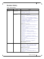
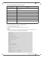
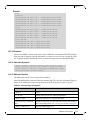
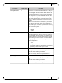
Revision History
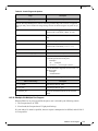
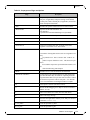
Table 1 - Revision History
Document Revision
Rev 4.70
Date
June 29, 2014
Changes
Updated the following section:
•
May 4, 2014
Section 8.7.2.2.1, “Using Global Pause Flow Control (GFC)”, on page 50
Updated the following sections:
•
•
•
•
•
Section 1.3, “WinOF Set of Documentation”, on
page 16
Section 5.3, “Firmware Upgrade”, on page 27
Section 8.10.4.2, “Enabling SR-IOV in Mellanox
WinOF Package”, on page 66
Section 10.3.1, “Verifying Network Adapter Configuration”, on page 80
Section 15.2, “Ethernet Troubleshooting”, on
page 162
Added the following sections:
•
•
•
•
•
•
•
•
•
•
Section 4, “Installing Mellanox WinOF Driver”,
on page 20
Section 5, “Uninstalling Mellanox WinOF
Driver”, on page 27
Section 8.8.4, “Removing NVGRE configuration”,
on page 55
Section 8.10, “SR-IOV”, on page 58
Section 8.11, “Virtual Ethernet Adapter”, on
page 72
Section 8.12, “IPoIB SR-IOV over KVM”, on
page 74
Section 8.13, “Lossless TCP”, on page 74
Section 9, “Booting Windows from an iSCSI Target”, on page 77
Section 15.4, “General Troubleshooting”, on
page 166
Section C, “Registry Keys”, on page 174
Removed the following sections:
•
Rev 4.60
February 13, 2014
Documentation
Updated the following sections:
•
•
Section 8.1, “Hyper-V with VMQ”, on page 36
Section 8.8.1, “Enabling/Disabling NVGRE
Offloading”, on page 53
Added the following sections:
•
•
Section 8.8.3, “Verifying the Encapsulation of the
Traffic”, on page 55
Section 8.11, “Virtual Ethernet Adapter”, on
page 72
Mellanox Technologies
9
Rev 4.70
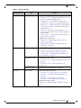
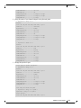
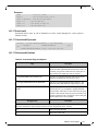
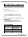
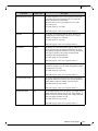
Table 1 - Revision History
Document Revision
Date
December 30, 2013
Changes
Updated the following sections:
Section 8.7.2.2, “Configuring Windows Host”, on
page 50 - Updated the example in Step 5
• Section 11.1.4.1, “Performance Tuning Tool
Application”, on page 85 - Updated the Options table
• Section 11.2, “Application Specific Optimization
and Tuning”, on page 89 - Removed the “Bus-master
•
DMA Operations”
•
Section 12, “OpenSM - Subnet Manager”, on
page 98 - Added an option of how to register OpemSM via
the PowerShell
•
Section 8.8.2, “Configuring the NVGRE using
PowerShell”, on page 54
Added the following sections:
•
•
Rev 4.55
December 15, 2013
Updated the following sections:
•
•
November 07, 2013
Section 8.8, “Network Virtualization using
Generic Routing Encapsulation”, on page 52
Section 8.8.2, “Configuring the NVGRE using
PowerShell”, on page 54
Updated the following sections:
• Section 8.7.2.2, “Configuring Windows
•
Rev 4.40
Section 7.4, “Configuring Quality of Service
(QoS)”, on page 34
Appendix B: “NVGRE Configuration Scrips
Examples,” on page 171
Host”, on
page 50
Section 14.4.19.1, “NTttcp Synopsis”, on
page 161
October 03, 2013
Added support for Windows Server 2012 R2
July 17, 2013
Updated the following sections:
• Section 8.7.1, “RoCE Overview”, on page 48
• Section 12, “OpenSM - Subnet Manager”, on
page 98
• Section 14.4.19, “NTttcp”, on page 160
• Section 15, “Troubleshooting”, on page 162
Added the following sections:
Appendix A: “Windows MPI (MS-MPI),” on page
168
Mellanox Technologies
10
Rev 4.70
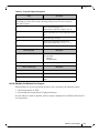
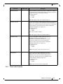
Table 1 - Revision History
Document Revision
Date
June 10, 2013
Changes
Updated the following sections:
• Section 6.2, “Downloading Mellanox Firmware
Tools”, on page 27
Section 14, “InfiniBand Fabric Utilities”, on
page 100
• Section 15, “Troubleshooting”, on page 162
• Section 1.3, “WinOF Set of Documentation”, on
page 16
• Section , “Options”, on page 86
•
Added the following sections:
• “perf_tuning”Appendix ,“Synopsis,” on page 86
• Section 6.3.1, “Upgrading Firmware Manually”,
•
•
Rev 4.2
October 20, 2012
on page 28
Section 8.7.2, “RoCE Configuration”, on page 49
Section 11.4, “Adapter Proprietary Performance
Counters”, on page 92
Added the following sections:
•
Section 10, “Deploying Windows Server 2012 and
Above with SMB Direct”, on page 80, and its subsections
Section 8.2, “Header Data Split”, on page 37
Section 14.2, “part_man - Virtual IPoIB Port Creation Utility”, on page 100
Updated Section 11, “Performance Tuning”, on
page 83
•
•
Rev 3.2.0
July 23, 2012
•
No changes
Rev 3.1.0
May 21, 2012
•
•
•
•
•
•
Added section Tuning the IPoIB Network Adapter
Added section Tuning the Ethernet Network Adapter
Added section Performance tuning tool application
Removed section Tuning the Network Adapter
Removed section part_man
Removed section ibdiagnet
Mellanox Technologies
11
Rev 4.70
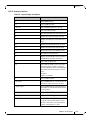
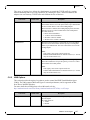
Table 1 - Revision History
Document Revision
Rev 3.0.0
Date
February 08, 2012
Changes
•
•
•
•
•
•
•
•
•
•
•
•
•
•
•
•
Added section RDMA over Converged Ethernet (RoCE) and
its subsections
Added section Hyper-V with VMQ
Added section Network Driver Interface Specification (NDIS)
Added section Header Data Split
Added section Auto Sensing
Added section Adapter Teaming
Added section Port Protocol Configuration
Added section Advanced Configuration for InfiniBand Driver
Added section Advanced Configuration for Ethernet Driver
Added section Updated section Tunable Performance Parameters
Added section Merged Ethernet and InfiniBand features sections
Removed section Sockets Direct Protocol and its subsections
Removed section Winsock Direct and Protocol and its subsections
Removed section Added ConnectX®-3 support
Removed section IPoIB Drivers Overview
Removed section Booting Windows from an iSCSI Target
Rev 2.1.3
January 28. 2011
Complete restructure
Rev 2.1.2
October 10, 2010
•
•
•
•
Removed section Debug Options.
Updated Section 3, “Uninstalling Mellanox VPI Driver,” on
page 11
Added Section 6, “InfiniBand Fabric,” on page 38 and its subsections
Added Section 6.3, “InfiniBand Fabric Performance Utilities,”
on page 71 and its subsections
Rev 2.1.1.1
July 14, 2010
•
Rev 2.1.1
May 2010
First release
Removed all references of InfiniHost® adapter since it is not
supported starting with WinOF VPI v2.1.1
Mellanox Technologies
12
Rev 4.70
About this Manual
Scope
The document describes WinOF Rev 4.70 features, performance, InfiniBand diagnostic, tools
content and configuration. Additionally, this document provides information on various performance tools supplied with this version.
Intended Audience
This manual is intended for system administrators responsible for the installation, configuration,
management and maintenance of the software and hardware of VPI (InfiniBand, Ethernet)
adapter cards. It is also intended for application developers.
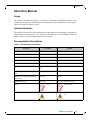
Documentation Conventions
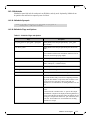
Table 2 - Documentation Conventions
Description
Convention
Example
File names
file.extension
Directory names
directory
Commands and their parameters
command param1
Required item
<>
Optional item
[ ]
Mutually exclusive parameters
{ p1, p2, p3 } or {p1 | p2 |
p3}
Optional mutually exclusive parameters
[ p1 | p2 | p3 ]
Variables for which users supply specific values
Italic font
enable
Emphasized words
Italic font
These are emphasized words
mts3610-1 > show hosts
Note
<text>
This is a note..
Warning
<text>
May result in system instability.
Mellanox Technologies
13
Rev 4.70
Common Abbreviations and Acronyms
Table 3 - Abbreviations and Acronyms
Abbreviation / Acronym
Whole Word / Description
B
(Capital) ‘B’ is used to indicate size in bytes or multiples of bytes
(e.g., 1KB = 1024 bytes, and 1MB = 1048576 bytes)
b
(Small) ‘b’ is used to indicate size in bits or multiples of bits (e.g.,
1Kb = 1024 bits)
FW
Firmware
HCA
Host Channel Adapter
HW
Hardware
IB
InfiniBand
LSB
Least significant byte
lsb
Least significant bit
MSB
Most significant byte
msb
Most significant bit
NIC
Network Interface Card
SW
Software
VPI
Virtual Protocol Interconnect
IPoIB
IP over InfiniBand
PFC
Priority Flow Control
PR
Path Record
RDS
Reliable Datagram Sockets
RoCE
RDMA over Converged Ethernet
SL
Service Level
MPI
Message Passing Interface
EoIB
Ethernet over InfiniBand
QoS
Quality of Service
ULP
Upper Level Protocol
VL
Virtual Lane
Mellanox Technologies
14
Rev 4.70
Related Documents
Table 4 - Related Documents
Document
MFT User Manual
Description
Describes the set of firmware management tools for a single InfiniBand
node. MFT can be used for:
•
•
WinOF Release Notes
Generating a standard or customized Mellanox firmware image Querying for
firmware information
Burning a firmware image to a single InfiniBand node
For possible software issues, please refer to WinOF Release Notes.
Mellanox Technologies
15
Rev 4.70
1
Introduction
This User Manual describes installation, configuration and operation of Mellanox WinOF driver
Rev 4.70 package.
Mellanox WinOF is composed of several software modules that contain InfiniBand and Ethernet
drivers. The Mellanox WinOF driver supports 10 or 40 Gb/s Ethernet, and 40 or 56 Gb/s InfiniBand network ports. The port type is determined upon boot based on card capabilities and user
settings.
For more details please refer to MFT User Manual.
1.1
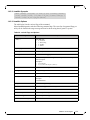
Hardware and Software Requirements
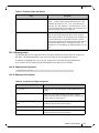
Table 5 - Hardware and Software Requirements
Requirements
Description
Required Disk Space for Installation
100MB
Operating Systems
•
•
•
Windows Server 2008 R2 (64 bit only)
Windows Server 2012 (64 bit only)
Windows Server 2012 R2 (64 bit only)
Note: The Operating System listed above must run
with administrator privileges.
1.2
Supplied Packages
Mellanox WinOF driver Rev 4.70 includes the following package:
•
MLNX_VPI_WinOF-<version>_All_<OS>_<arch>.exe:
In this package, the port default is auto, RoCE is enabled
1.3
WinOF Set of Documentation
Under <installation_directory>\Documentation:
•
License file
•
User Manual (this document)
•
MLNX_VPI_WinOF Release Notes
Mellanox Technologies
16
Rev 4.70
2
Downloading Mellanox WinOF Driver
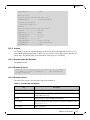
Follow these steps to download the .exe according to your Operating System.
Step 1. Verify the machine architecture.
For Windows Server 2008 R2
1. Open a CMD console (Click start-->Run and enter CMD).
2. Enter the following command.
> echo %PROCESSOR_ARCHITECTURE%
On an x64 (64-bit) machine, the output will be “AMD64”.
For Windows Server 2012 / 2012 R2
1. To go to the Start menu.
Position your mouse in the bottom-right corner of the Remote Desktop of your screen.
2. Open a CMD console (Click Task Manager-->File --> Run new task --> and enter
CMD).
3. Enter the following command.
> echo %PROCESSOR_ARCHITECTURE%
On an x64 (64-bit) machine, the output will be “AMD64”.
Step 2. Go to the Mellanox WinOF web page at
http://www.mellanox.com > Products > InfiniBand/VPI Drivers => Windows SW/Drivers.
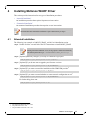
Step 3. Download the .exe image according to the architecture of your machine (see Step 1) and the
operating system. The name of the .exe is in the following format
MLNX_VPI_WinOF-<version>_All_<OS>_<arch>.exe.
Installing the incorrect .exe file is prohibited. If you do so, an error message will be displayed. For example, if you try to install a 64-bit .exe on a 32-bit machine, the wizard
will display the following (or a similar) error message:
Mellanox Technologies
17
Rev 4.70
3
Extracting Files Without Running Installation
To extract the files without running installation, perform the following steps.
Step 1. Open a CMD console [Windows Server 2008 R2] - Click Start-->Run and enter CMD.
[Windows Server 2012 / 2012 R2] - Click Start --> Task Manager-->File --> Run new task -->
and enter CMD.
Step 2. Extract the driver and the tools:
MLNX_VPI_WinOF-<version>_All_<OS>_<arch>.exe /a
•
To extract only the driver files.
MLNX_VPI_WinOF-<version>_All_<OS>_<arch>.exe /a /vMT_DRIVERS_ONLY=1
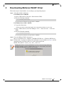
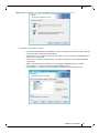
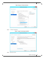
Step 3. Click Next to create a server image.
Step 4. Click Change and specify the location in which the files are extracted to.
Mellanox Technologies
18
Rev 4.70
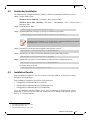
Step 5. Click Install to extract this folder, or click Change to install to a different folder.
Step 6. To complete the extraction, click Finish.
Mellanox Technologies
19
Rev 4.70
4
Installing Mellanox WinOF Driver
This section provides instructions for two types of installation procedures:
•
“Attended Installation”
An installation procedure that requires frequent user intervention.
•
“Unattended Installation”
An automated installation procedure that requires no user intervention.
Both Attended and Unattended installations require administrator privileges.
4.1
Attended Installation
The following is an example of a MLNX_WinOF_win2012 x64 installation session.
Step 1. Double click the .exe and follow the GUI instructions to install MLNX_WinOF.
Starting from MLNX WinOF v4.55, the log option is enabled automatically.
The default path of the log is: %LOCALAPPDATA%\MLNX_WinOF.log0
Step 2. [Optional] Manually configure your setup to contain the logs option.
MLNX_VPI_WinOF-4.70_All_win2012_x64.exe /v"/l*vx [LogFile]"
Step 3. [Optional] If you do not want to upgrade your firmware version1.
MLNX_VPI_WinOF-4.70_All_win2012_x64.exe /v" MT_SKIPFWUPGRD=1"
Step 4. [Optional] If you want to control the installation of the WMI/CIM provider2.
MLNX_VPI_WinOF-4.70_All_win2012_x64.exe /v" MT_WMI=1"
Step 5. [Optional] If you want to control whether to restore network configuration or not3.
MLNX_VPI_WinOF-4.70_All_win2012_x64.exe /v" MT_RESTORECONF=1"
For further help, please run:
MLNX_VPI_WinOF-4.70_All_win2012_x64.exe /v" /h"
1. MT_SKIPFWUPGRD default value is False
2. MT_WMI default value is True
3. MT_RESTORECONF default value is True
Mellanox Technologies
20
Rev 4.70
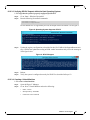
Step 6. Click Next in the Welcome screen.
Step 7. Read then accept the license agreement and click Next.
Step 8. Select the target folder for the installation.
Mellanox Technologies
21
Rev 4.70
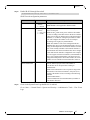
Step 9. The firmware upgrade screen will be displayed in the following cases:
•
If the user has an OEM card, in this case the firmware will not be updated.
•
If the user has a standard Mellanox card with an older firmware version, the firmware will be updated
accordingly. However, if the user has both OEM card and Mellanox card, only Mellanox card will be
updated.
Step 10. Configure your system for maximum performance by checking the maximum performance box.
This step requires rebooting your machine at the end of the installation.
Mellanox Technologies
22
Rev 4.70
Step 11. Select a Complete or Custom installation, follow Step a and on, on page 23.
a. Select the desired feature to install:
• OpenSM - installs Windows OpenSM that is required to manage the subnet from a host. OpenSM
is part of the driver and installed automatically.
• Performances tools - install the performance tools that are used to measure the InfiniBand performance in user environment.
• Analyze tools - install the tools that can be used either to diagnosed or analyzed the InfiniBand
environment.
• SDK - contains the libraries and DLLs for developing InfiniBand application over IBAL.
• Documentation - contains the User Manual and Installation Guide.
• ND FLTR DLLs - contains the files for standalone installation of the mlx4nd provider.
Mellanox Technologies
23
Rev 4.70
b. Click Install to start the installation.
Step 12. Click Finish to complete the installation.
•
If the firmware upgrade and the restore of the network configuration failed, the following message
will be displayed.
Mellanox Technologies
24
Rev 4.70
4.2
Unattended Installation
The following is an example of a MLNX_WinOF_win2012 x64 unattended installation session.
Step 1. Open a CMD console
[Windows Server 2008 R2] - Click Start-->Run and enter CMD.
[Windows Server 2012 / 2012 R2] - Click Start --> Task Manager-->File --> Run new task -->
and enter CMD.
Step 2. Install the driver. Run:
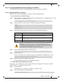
> MLNX_VPI_WinOF-4.70_All_win2012_x64.exe /S /v"/qn"
Step 3. [Optional] Manually configure your setup to contain the logs option:
> MLNX_VPI_WinOF-4.70_All_win2012_x64.exe /S /v"/qn" /v"/l*vx [LogFile]"
Starting from MLNX WinOF v4.55, the log option is enabled automatically. The default
path of the log is: %LOCALAPPDATA%\MLNX_WinOF.log0
Step 4. [Optional] If you do not want to upgrade your firmware version1.
MLNX_VPI_WinOF-4.70_All_win2012_x64.exe /v" MT_SKIPFWUPGRD=1"
Step 5. [Optional] If you want to control the installation of the WMI/CIM provider2.
MLNX_VPI_WinOF-4.70_All_win2012_x64.exe /v" /MT_WMI=1"
Step 6. [Optional] If you want to control whether to restore network configuration or not3.
MLNX_VPI_WinOF-4.70_All_win2012_x64.exe /v" MT_RESTORECONF=1"
For further help, please run:
> MLNX_VPI_WinOF-4.70_All_win2012_x64.exe /v" /h"
4.3
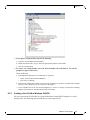
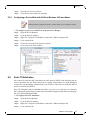
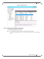
Installation Results
Upon installation completion, you can verify the successful addition of the network card(s)
through the Device Manager.
Upon installation completion, the inf files can be located at:
•
•
•
%ProgramFiles%\Mellanox\MLNX_VPI\ETH
%ProgramFiles%\Mellanox\MLNX_VPI\HW\mlx4_bus
%ProgramFiles%\Mellanox\MLNX_VPI\IB\IPoIB
To see the Mellanox network adapter device, and the Ethernet or IPoIB network device
(depending on the used card) for each port, display the Device Manager and expand “System
devices” or “Network adapters”.
1. MT_SKIPFWUPGRD default value is False
2. MT_WMI default value is True
3. MT_RESTORECONF default value is True
Mellanox Technologies
25
Rev 4.70
Figure 1: Installation Results
Mellanox Technologies
26
Rev 4.70
5
Uninstalling Mellanox WinOF Driver
5.1
Attended Uninstall
To uninstall MLNX_WinOF on a single node:
1. Click Start-> Control Panel-> Programs and Features-> MLNX_VPI-> Uninstall.
(NOTE: This requires elevated administrator privileges – see Section 1.1, “Hardware and
Software Requirements”, on page 16 for details.)
2. Double click the .exe and follow the instructions of the install wizard.
3. Click Start -> All Programs -> Mellanox Technologies -> MLNX_WinOF ->
Uninstall MLNX_WinOF.
5.2
Unattended Uninstall
To uninstall MLNX_WinOF in unattended mode:
Step 1. Open a CMD console
[Windows Server 2008 R2] - Click Start-->Run and enter CMD.
[Windows Server 2012 / 2012 R2] - Click Start --> Task Manager-->File --> Run new task -->
and enter CMD.
Step 2. Uninstall the driver. Run:
MLNX_VPI_WinOF-4.70_All_win2012_x64.exe /S /x /v"/qn"
5.3
Firmware Upgrade
For information on how to upgrade firmware please refer to MFT User Manual:
www.mellanox.com ->Products -> Adapter IB/VPI SW ->Firmware Tools
Mellanox Technologies
27
Rev 4.70
6
Upgrading Mellanox WinOF Driver
The upgrade process differs between various Operating Systems.
•
Windows Server 2008 R2:
When upgrading from WinOF version 3.2.0 to version 4.40 and above, the MLNX_WinOF driver
upgrades the driver automatically by uninstalling the previous version and installing the new driver.
The existing configuration files are not saved upon driver upgrade.
•
Windows Server 2012 and above:
• When upgrading from WinOF version 4.2 to version 4.40 and above, the MLNX_WinOF
driver does not completely uninstall the previous version, but rather upgrades only the
components that require upgrade. The network configuration is saved upon driver
upgrade.
• When upgrading from Inbox or any other version, the network configuration is automatically saved upon driver upgrade.
Mellanox Technologies
28
Rev 4.70
7
Advanced Driver Configuration
Once you have installed Mellanox WinOF VPI package, you can perform various modifications
to your driver to make it suitable for your system’s needs
Changes made to the Windows registry happen immediately, and no backup is automatically made.
Do not edit the Windows registry unless you are confident regarding the changes.
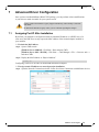
7.1
Assigning Port IP After Installation
By default, your machine is configured to obtain an automatic IP address via a DHCP server. In
some cases, the DHCP server may require the MAC address of the network adapter installed in
your machine.
To obtain the MAC address:
Step 1. Open a CMD console
[Windows Server 2008 R2] - Click Start-->Run and enter CMD.
[Windows Server 2012 / 2012 R2] - Click Start --> Task Manager-->File --> Run new task -->
and enter CMD.
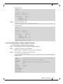
Step 2. Display the MAC address as “Physical Address”
ipconfig /all
Configuring a static IP is the same for both IPoIB and Ethernet adapters.
To assign a static IP address to a network port after installation:
Step 1. Open the Network Connections window. Locate Local Area Connections with Mellanox devices.
Mellanox Technologies
29
Rev 4.70
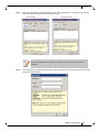
Step 2. Right-click a Mellanox Local Area Connection and left-click Properties.
Step 3. Select Internet Protocol Version 4 (TCP/IPv4) from the scroll list and click Properties.
Step 4. Select the “Use the following IP address:” radio button and enter the desired IP information.
Step 5. Click OK.
Step 6. Close the Local Area Connection dialog.
Mellanox Technologies
30
Rev 4.70
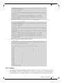
Step 7. Verify the IP configuration by running ‘ipconfig’ from a CMD console.
> ipconfig
...
Ethernet adapter Local Area Connection 4:
Connection-specific
IP Address. . . . .
Subnet Mask . . . .
Default Gateway . .
DNS
..
..
..
Suffix
....
....
....
.
.
.
.
:
: 11.4.12.63
: 255.255.0.0
:
...
7.2
Configuring the InfiniBand Driver
7.2.1
Modifying IPoIB Configuration
To modify the IPoIB configuration after installation, perform the following steps:
Step 1.
Open Device Manager and expand Network Adapters in the device display pane.
Step 2.
Right-click the Mellanox IPoIB Adapter entry and left-click Properties.
Step 3.
Click the Advanced tab and modify the desired properties.
The IPoIB network interface is automatically restarted once you finish modifying IPoIB
parameters. Consequently, it might affect any running traffic.
Mellanox Technologies
31
Rev 4.70
7.2.2
Displaying Adapter Related Information
To display a summary of network adapter software, firmware- and hardware-related information
such as driver version, firmware version, bus interface, adapter identity, and network port link
information, perform the following steps:
Step 1.
Display the Device Manager.
Step 2.
Select the Information tab from the Properties sheet.
To save this information for debug purposes, click Save to File and provide the output
file name.
Mellanox Technologies
32
Rev 4.70
7.3
Configuring the Ethernet Driver
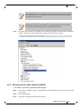
The following steps describe how to configure advanced features.
Step 1.
Display the Device Manager.
Step 2.
Right-click a Mellanox network adapter (under “Network adapters” list) and left-click Properties. Select the Advanced tab from the Properties sheet.
Mellanox Technologies
33
Rev 4.70
Step 3.
Modify configuration parameters to suit your system.
Please note the following:
a. For help on a specific parameter/option, check the help button at the bottom of the
dialog.
b. If you select one of the entries Off-load Options, Performance Options, or Flow
Control Options, you’ll need to click the Properties button to modify parameters via
a pop-up dialog.
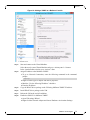
7.4
Configuring Quality of Service (QoS)
Prior to configuring Quality of Service, you must install Data Center Bridging using one of the
following methods:
To install the Data Center Bridging using the Server Manager:
Step 1.
Open the 'Server Manager'.
Step 2.
Select 'Add Roles and Features'.
Step 3.
Click Next.
Step 4.
Select 'Features' on the left panel
Step 5.
Check the 'Data Center Bridging' checkbox.
Step 6.
Click 'Install'.
To install the Data Center Bridging using PowerShell:
Step 1.
Enable Data Center Bridging (DCB).
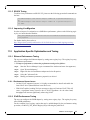
PS $ Install-WindowsFeature Data-Center-Bridging
To configure QoS on the host:
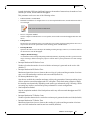
The procedure below is not saved after you reboot your system. Hence, we recommend
you create a script using the steps below and run it on the local machine.
Please see the procedure below on how to add the script to the local machine startup
scripts.
Step 1.
Change the Windows PowerShell execution policy.
PS $ Set-ExecutionPolicy AllSigned
Step 2.
Remove the entire previous QoS configuration.
PS $ Remove-NetQosTrafficClass
PS $ Remove-NetQosPolicy -Confirm:$False
Step 3.
Set the DCBX Willing parameter to false as Mellanox drivers do not support this feature.
PS $ set-NetQosDcbxSetting -Willing 0
Step 4.
Create a Quality of Service (QoS) policy and tag each type of traffic with the relevant priority.
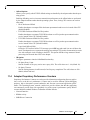
In this example we used TCP/UDP priority 1, ND/NDK priority 3.
PS $ New-NetQosPolicy "SMB" -store Activestore -NetDirectPortMatchCondition 445 PriorityValue8021Action 3
PS $ New-NetQosPolicy "DEFAULT" -store Activestore -Default -PriorityValue8021Action 3
PS $ New-NetQosPolicy "TCP" -store Activestore -IPProtocolMatchCondition TCP PriorityValue8021Action 1
PS $ New-NetQosPolicy "UDP" -store Activestore -IPProtocolMatchCondition UDP PriorityValue8021Action 1
Mellanox Technologies
34
Rev 4.70
Step 5.
[Optional] If VLANs are used, mark the egress traffic with the relevant VlanID.
The NIC is referred as "Ethernet 4” in the examples below.
PS $ Set-NetAdapterAdvancedProperty -Name "Ethernet 4" -RegistryKeyword "VlanID" -RegistryValue
"55"
Step 6.
[Optional] Configure the IP address for the NIC.
If DHCP is used, the IP address will be assigned automatically.
PS $ Set-NetIPInterface -InterfaceAlias “Ethernet 4” -DHCP Disabled
PS $ Remove-NetIPAddress -InterfaceAlias “Ethernet 4” -AddressFamily IPv4 -Confirm:$false
PS $ New-NetIPAddress -InterfaceAlias “Ethernet 4” -IPAddress 192.168.1.10 -PrefixLength 24 -Type
Unicast
Step 7.
[Optional] Set the DNS server (assuming its IP address is 192.168.1.2).
PS $ Set-DnsClientServerAddress -InterfaceAlias “Ethernet 4” -ServerAddresses 192.168.1.2
After establishing the priorities of ND/NDK traffic, the priorities must have PFC
enabled on them.
Step 8.
Disable Priority Flow Control (PFC) for all other priorities except for 3.
PS $ Disable-NetQosFlowControl 0,1,2,4,5,6,7
Step 9.
Enable QoS on the relevant interface.
PS $ Enable-NetAdapterQos -InterfaceAlias "Ethernet 4"
Step 10. Enable PFC on priority 3.
PS $ Enable-NetQosFlowControl -Priority 3
To add the script to the local machine startup scripts:
Step 1.
From the PowerShell invoke.
gpedit.msc
Step 2.
In the pop-up window, under the 'Computer Configuration' section, perform the following:
1. Select Windows Settings
2. Select Scripts (Startup/Shutdown)
3. Double click Startup to open the Startup Properties
4. Click Add
5. Browse for the script's location.
6. Click OK
Mellanox Technologies
35
Rev 4.70
8
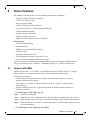
Driver Features
The Mellanox VPI WinOF driver release introduces the following capabilities:
•
Support for Single and Dual port Adapters
•
Up to 16 Rx queues per port
•
Rx steering mode (RSS)
•
Hardware Tx/Rx checksum calculation
•
Large Send off-load (i.e., TCP Segmentation Off-load)
•
Hardware multicast filtering
• Adaptive interrupt moderation
•
Support for MSI-X interrupts
•
Support for Auto-Sensing of Link level protocol
Ethernet Only:
•
Hardware VLAN filtering
•
Header Data Split
•
RDMA over Converged Ethernet (RoCE)
•
DSCP over IPv4
•
RoCEv2 in ConnectX®-3 Pro
•
NVGRE hardware off-load in ConnectX®-3 Pro
•
Ports TX arbitration/Bandwidth allocation per port
For the complete list of Ethernet and InfiniBand Known Issues and Limitations, WinOF Release
Notes (www.mellanox.com -> Products -> InfiniBand/VPI Drivers -> Windows SW/Drivers).
8.1
Hyper-V with VMQ
Mellanox WinOF Rev 4.70 includes a Virtual Machine Queue (VMQ) interface to support
Microsoft Hyper-V network performance improvements and security enhancement.
VMQ interface supports:
•
Classification of received packets by using the destination MAC address to route the
packets to different receive queues
•
NIC ability to use DMA to transfer packets directly to a Hyper-V child-partition's
shared memory
•
Scaling to multiple processors, by processing packets for different virtual machines on
different processors.
To enable Hyper-V with VMQ using UI:
Step 1.
Open Hyper-V Manager.
Step 2.
Right-click the desired Virtual Machine (VM), and left-click Settings in the pop-up menu.
Step 3.
In the Settings window, under the relevant network adapter, select “Hardware Acceleration”.
Step 4.
Check/uncheck the box “Enable virtual machine queue” to enable/disable VMQ on that specific network adapter.
To enable Hyper-V with VMQ using PowerShell:
Mellanox Technologies
36
Rev 4.70
8.2
Step 1.
Enable VMQ on a specific VM: Set-VMNetworkAdapter <VM Name> -VmqWeight 100
Step 2.
Disable VMQ on a specific VM: Set-VMNetworkAdapter <VM Name> -VmqWeight 0
Header Data Split
The header-data split feature improves network performance by splitting the headers and data in
received Ethernet frames into separate buffers. The feature is disabled by default and can be
enabled in the Advanced tab (Performance Options) from the Properties window.
For further information, please refer to the MSDN library:
http://msdn.microsoft.com/en-us/library/windows/hardware/ff553723(v=VS.85).aspx
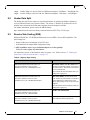
8.3
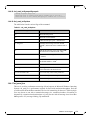
Receive Side Scaling (RSS)
Mellanox WinOF Rev 4.70 IPoIB and Ethernet drivers use NDIS 6.30 new RSS capabilities. The
main changes are:
•
Removed the previous limitation of 64 CPU cores
•
Individual network adapter RSS configuration usage
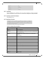
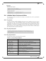
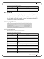
RSS capabilities can be set per individual adapters as well as globally.
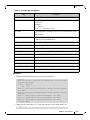
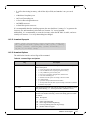
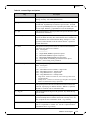
To do so, set the registry keys listed below:
For instructions on how to find interface index in registry <nn>, Please refer to C.2 “Finding the
Index Value of the Network Interface,” on page 175.
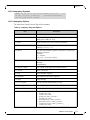
Table 6 - Registry Keys Setting
Sub-key
Description
HKLM\SYSTEM\CurrentControlSet\Control\Class\{4d36e972-e325-11ce-bfc108002be10318}\<nn>\*MaxRSSProcessors
Maximum number of CPUs allotted. Sets
the desired maximum number of processors
for each interface. The number can be different for each interface.
Note: Restart the network adapter after you
change this registry key.
HKLM\SYSTEM\CurrentControlSet\Control\Class\{4d36e972-e325-11ce-bfc108002be10318}\<nn>\*RssBaseProcNumber
Base CPU number. Sets the desired base
CPU number for each interface. The number
can be different for each interface. This
allows partitioning of CPUs across network
adapters.
Note: Restart the network adapter when you
change this registry key.
HKLM\SYSTEM\CurrentControlSet\Control\Class\{4d36e972-e325-11ce-bfc108002be10318}\<nn>\*NumaNodeID
NUMA node affinitization
HKLM\SYSTEM\CurrentControlSet\Control\Class\{4d36e972-e325-11ce-bfc108002be10318}\<nn>\*RssBaseProcGroup
Sets the RSS base processor group for systems with more than 64 processors.
Mellanox Technologies
37
Rev 4.70
8.4
Port Configuration
8.4.1
Auto Sensing
Auto Sensing enables the NIC to automatically sense the link type (InfiniBand or Ethernet) based
on the cable connected to the port and load the appropriate driver stack (InfiniBand or Ethernet).
Auto Sensing is performed only when rebooting the machine or after disabling/enabling the
mlx4_bus interface from the Device Manager. Hence, if you replace cables during the runtime,
the NIC will not perform Auto Sensing.
For further information on how to configure it, please refer to Section 8.4.2, “Port Protocol Configuration”, on page 38.
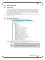
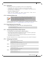
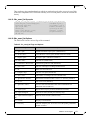
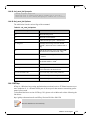
8.4.2
Port Protocol Configuration
Step 1.
Display the Device Manager and expand “System devices”.
Step 2.
Right-click on the Mellanox ConnectX Ethernet network adapter and left-click Properties.
Select the Port Protocol tab from the Properties window.
The “Port Protocol” tab is displayed only if the NIC is a VPI (IB and ETH).
Mellanox Technologies
38
Rev 4.70
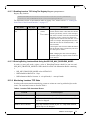
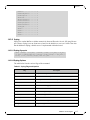
The figure below is an example of the displayed Port Protocol window for a dual port VPI
adapter card.
Step 3.
In this step, you can perform the following functions:
•
If you choose the HW Defaults option, the port protocols will be determined according to the NIC’s
hardware default values.
•
Choose the desired port protocol for the available port(s). If you choose IB or ETH, both ends of the
connection must be of the same type (IB or ETH).
•
Enable Auto Sensing by checking the AUTO checkbox. If the NIC does not support Auto Sensing,
the AUTO option will be grayed out.
If you choose AUTO, the current setting will indicate the actual port settings: IB or
ETH.
8.5
Load Balancing, Fail-Over (LBFO) and VLAN
Windows Server 2012 and above supports load balancing as part of the operating system. Please
refer to Microsoft guide “NIC Teaming in Windows Server 2012” following the link below:
http://social.technet.microsoft.com/wiki/contents/articles/14951.nic-teaming-in-windows-server2012.aspx
For other earlier operating systems, please refer to the sections below.
8.5.1
Adapter Teaming
Adapter teaming can group a group of ports inside a network adapter or a number of physical network adapters into virtual adapters that provide the fault-tolerance and load-balancing functions.
Depending on the teaming mode, one or more interfaces can be active. The non-active interfaces
in a team are in a standby mode and will take over the network traffic in the event of a link failure
in the active interfaces. All of the active interfaces in a team participate in load-balancing operations by sending and receiving a portion of the total network traffic.
Mellanox Technologies
39
Rev 4.70
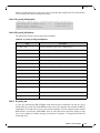
8.5.1.1 Teaming (Bundle) Modes
1. Fault Tolerance
Provides automatic redundancy for the server’s network connection. If the primary adapter
fails, the secondary adapter (currently in a standby mode) takes over. Fault Tolerance is the
basis for each of the following teaming types and is inherent in all teaming modes.
2. Switch Fault Tolerance
Provides a failover relationship between two adapters when each adapter is connected to a
separate switch.
3. Send Load Balancing
Provides load balancing of transmit traffic and fault tolerance. The load balancing performs
only on the send port.
4. Load Balancing (Send & Receive)
Provides load balancing of transmit and receive traffic and fault tolerance. The load balancing
splits the transmit and receive traffic statically among the team adapters (without changing
the base of the traffic loading) based on the source/destination MAC and IP addresses.
5. Adaptive Load Balancing
The same functionality as Load Balancing (Send & Receive). In case of traffic load in one of
the adapters, the load balancing channels the traffic between the other team adapter.
6. Dynamic Link Aggregation (802.3ad)
Provides dynamic link aggregation allowing creation of one or more channel groups using
same speed or mixed-speed server adapters.
7. Static Link Aggregation (802.3ad)
Provides increased transmission and reception throughput in a team comprised of two to eight
adapter ports through static configuration.
If the switch connected to the HCA supports 802.3ad the recommended setting is teaming mode 6.
8.5.2
Creating a Load Balancing and Fail-Over (LBFO) Bundle
LBFO is used to balance the workload of packet transfers by distributing the workload over a
bundle of network instances and to set a secondary network instance to take over packet indications and information requests if the primary network instance fails.
The following steps describe the process of creating an LBFO bundle.
Mellanox Technologies
40
Rev 4.70
Step 1.
Display the Device Manager.
Step 2.
Right-click a Mellanox ConnectX 10Gb Ethernet adapter (under “Network adapters” list) and
left click Properties. Select the LBFO tab from the Properties window.
It is not recommended to open the Properties window of more than one adapter simultaneously.
The LBFO dialog enables creating, modifying or removing a bundle.
Only Mellanox Technologies adapters can be part of the LBFO.
To create a new bundle, perform the following
Step 1.
Click Create.
Step 2.
Enter a (unique) bundle name.
Step 3.
Select a bundle type.
Mellanox Technologies
41
Rev 4.70
Step 4.
Select the adapters to be included in the bundle (that have not been associated with a VLAN).
Step 5.
[Optional] Select Primary Adapter.
An active-passive scenario used for data transfer of link disconnecting. In such scenario, the
system uses one of the other interfaces. When the primary link comes up, the LBFO interface
returns to transfer data using the primary interface. If the primary adapter is not selected, the
primary interface is selected randomly.
Step 6.
[Optional] Failback to Primary
Step 7.
Check the checkbox.
The newly created virtual Mellanox adapter representing the bundle will be displayed by the
Device Manager under “Network adapters” in the following format (see the figure below):
Mellanox Virtual Miniport Driver - Team <bundle_name>
Mellanox Technologies
42
Rev 4.70
To modify an existing bundle, perform the following:
a. Select the desired bundle and click Modify
b. Modify the bundle name, its type, and/or the participating adapters in the bundle
c. Click the Commit button
To remove an existing bundle, select the desired bundle and click Remove. You will be
prompted to approve this action.
Notes on this step:
a. Each adapter that participates in a bundle has two properties:
•
Status: Connected/Disconnected/Disabled
•
Role: Active or Backup
b. Each network adapter that is added or removed from a bundle gets refreshed (i.e. disabled then enabled).
This may cause a temporary loss of connection to the adapter.
c. In case a bundle loses one or more network adapters by a “create” or “modify” operation, the remaining
adapters in the bundle are automatically notified of the change.
8.5.3
Creating a Port VLAN in Windows 2008 R2
You can create a Port VLAN either on a physical Mellanox ConnectX® EN adapter or a virtual
bundle (team). The following steps describe how to create a port VLAN.
Mellanox Technologies
43
Rev 4.70
Step 1.
Display the Device Manager.
Mellanox Technologies
44
Rev 4.70
Step 2.
Right-click a Mellanox network adapter (under “Network adapters” list) and left-click Properties. Select the VLAN tab from the Properties sheet.
If a physical adapter has been added to a bundle (team), the VLAN tab will not be
displayed.
Step 3.
Click New to open a VLAN dialog window. Enter the desired VLAN Name and VLAN ID, and
select the VLAN Priority.
Mellanox Technologies
45
Rev 4.70
After installing the first virtual adapter (VLAN) on a specific port, the port becomes disabled. This means that it is not possible to bind to this port until all the virtual adapters
associated with it are removed.
When using a VLAN, the network address is configured using the VLAN ID. Therefore, the VLAN ID on both ends of the connection must be the same.
Step 4.
Verify the new VLAN(s) by opening the Device Manager window or the Network Connections
window. The newly created VLAN will be displayed in the following format.
Mellanox Virtual Miniport Driver - VLAN <name>
8.5.4
Removing a Port VLAN in Windows 2008 R2
To remove a port VLAN, perform the following steps:
Step 1.
In the Device Manager window, right-click the network adapter from which the port VLAN
was created.
Step 2.
Left-click Properties.
Step 3.
Select the VLAN tab from the Properties sheet.
Mellanox Technologies
46
Rev 4.70
8.5.5
Step 4.
Select the VLAN to be removed.
Step 5.
Click Remove and confirm the operation.
Configuring a Port to Work with VLAN in Windows 2012 and Above
In this procedure you DO NOT create a VLAN, rather use an existing VLAN ID.
To configure a port to work with VLAN using the Device Manager.
8.6
Step 1.
Open the Device Manager.
Step 2.
Go to the Network adapters.
Step 3.
Right click ' Properties on Mellanox ConnectX®-3 Ethernet Adapter card.
Step 4.
Go to Advanced tab.
Step 5.
Choose the VLAN ID in the Property window.
Step 6.
Set its value in the Value window.
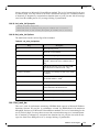
Ports TX Arbitration
On a setup with a dual-port NIC with both ports at link speed of 40GbE, each individual port can
achieve maximum line rate. When both ports are running simultaneously in a high throughput
scenario, the total throughput is bottlenecked by the PCIe bus, and in this case each port may not
achieve its maximum of 40GbE.
Ports TX Arbitration ensures bandwidth precedence is given to one of the ports on a dual-port
NIC, enabling the preferred port to achieve the maximum throughput and the other port taking up
the rest of the remaining bandwidth.
To configure Ports TX Arbitration:
Step 1.
Open the Device Manager.
Step 2.
Go to the Network adapters.
Step 3.
Right click ' Properties on Mellanox ConnectX®-3 Ethernet Adapter card.
Step 4.
Go to Advanced tab.
Mellanox Technologies
47
Rev 4.70
Step 5.
Choose the ‘Tx Throughput Port Arbiter’ option.
Step 6.
Set one of the following values:
•
Best Effort (Default) - Default behavior. No precedence is given to this port over the other.
•
Guaranteed - Give higher precedence to this port.
•
Not Present - No configuration exists, defaults are used.
8.7
RDMA over Converged Ethernet (RoCE)
8.7.1
RoCE Overview
Remote Direct Memory Access (RDMA) is the remote memory management capability that
allows server to server data movement directly between application memory without any CPU
involvement. RDMA over Converged Ethernet (RoCE) is a mechanism to provide this efficient
data transfer with very low latencies on loss-less Ethernet networks. With advances in data center
convergence over reliable Ethernet, ConnectX® EN with RoCE uses the proven and efficient
RDMA transport to provide the platform for deploying RDMA technology in mainstream data
center application at 10GigE and 40GigE link-speed. ConnectX® EN with its hardware offload
support takes advantage of this efficient RDMA transport (InfiniBand) services over Ethernet to
deliver ultra-low latency for performance-critical and transaction intensive applications such as
financial, database, storage, and content delivery networks. RoCE encapsulates IB transport and
GRH headers in Ethernet packets bearing a dedicated ether type. While the use of GRH is
optional within InfiniBand subnets, it is mandatory when using RoCE. Applications written over
IB verbs should work seamlessly, but they require provisioning of GRH information when creating address vectors. The library and driver are modified to provide mapping from GID to MAC
addresses required by the hardware.
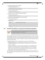
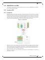
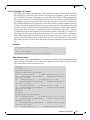
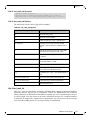
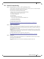
8.7.1.1 IP Routable (RoCEv2)
A straightforward extension of the RoCE protocol enables traffic to operate in layer 3 environments. This capability is obtained via a simple modification of the RoCE packet format. Instead
of the GRH used in RoCE, routable RoCE packets carry an IP header which allows traversal of
IP L3 Routers and a UDP header that serves as a stateless encapsulation layer for the RDMA
Transport Protocol Packets over IP.
Figure 2: RoCEv2 and RoCE Frame Format Differences
Mellanox Technologies
48
Rev 4.70
The proposed RoCEv2 packets use a well-known UDP destination port value that unequivocally
distinguishes the datagram. Similar to other protocols that use UDP encapsulation, the UDP
source port field is used to carry an opaque flow-identifier that allows network devices to implement packet forwarding optimizations (e.g. ECMP) while staying agnostic to the specifics of the
protocol header format.
Furthermore, since this change exclusively affects the packet format on the wire, and due to the
fact that with RDMA semantics packets are generated and consumed below the AP applications
can seamlessly operate over any form of RDMA service (including the routable version of RoCE
as shown in Figure 2), in a completely transparent way1.
Figure 3: RoCEv2 Protocol Stack
8.7.2
RoCE Configuration
In order to function reliably, RoCE requires a form of flow control. While it is possible to use
global flow control, this is normally undesirable, for performance reasons.
The normal and optimal way to use RoCE is to use Priority Flow Control (PFC). To use PFC, it
must be enabled on all endpoints and switches in the flow path.
In the following section we present instructions to configure PFC on Mellanox ConnectX™
cards. There are multiple configuration steps required, all of which may be performed via PowerShell. Therefore, although we present each step individually, you may ultimately choose to write
a PowerShell script to do them all in one step. Note that administrator privileges are required for
these steps.
For further information, please refer to:
http://blogs.technet.com/b/josebda/archive/2012/07/31/deploying-windows-server-2012-withsmb-direct-smb-over-rdma-and-the-mellanox-connectx-3-using-10gbe-40gbe-roce-step-bystep.aspx
1. Standard RDMA APIs are IP based already for all existing RDMA technologies
Mellanox Technologies
49
Rev 4.70
8.7.2.1 Prerequisites
The following are the driver’s prerequisites in order to set or configure RoCE:
•
ConnectX®-3 and ConnectX®-3 Pro firmware version 2.30.3000 or higher
•
All InfiniBand verbs applications which run over InfiniBand verbs should work on
RoCE links if they use GRH headers.
•
Set HCA to use Ethernet protocol:
Display the Device Manager and expand “System Devices”. Please refer to
Section 8.4.2, “Port Protocol Configuration”, on page 38.
8.7.2.2 Configuring Windows Host
Since PFC is responsible for flow controlling at the granularity of traffic priority, it is
necessary to assign different priorities to different types of network traffic.
As per RoCE configuration, all ND/NDK traffic is assigned to one or more chosen priorities, where PFC is enabled on those priorities.
Configuring Windows host requires configuring QoS. To configure QoS, please follow the procedure described in Section 7.4, “Configuring Quality of Service (QoS)”, on page 34
8.7.2.2.1 Using Global Pause Flow Control (GFC)
To use Global Pause Flow Control (GFC) mode, disable QoS and Priority:
PS $ Disable-NetQosFlowControl
PS $ Disable-NetAdapterQos <interface name>
8.7.3
Configuring SwitchX® Based Switch System
To enable RoCE, the SwitchX should be configured as follows:
•
Ports facing the host should be configured as access ports, and either use global pause
or Port Control Protocol (PCP) for priority flow control
•
Ports facing the network should be configured as trunk ports, and use Port Control Protocol (PCP) for priority flow control
For further information on how to configure SwitchX, please refer to SwitchX User Manual.
8.7.4
Configuring Arista Switch
Step 1.
Set the ports that face the hosts as trunk.
(config)# interface et10
(config-if-Et10)# switchport mode trunk
Step 2.
Set VID allowed on trunk port to match the host VID.
(config-if-Et10)# switchport trunk allowed vlan 100
Step 3.
Set the ports that face the network as trunk.
(config)# interface et20
(config-if-Et20)# switchport mode trunk
Step 4.
Assign the relevant ports to LAG.
(config)# interface et10
(config-if-Et10)# dcbx mode ieee
Mellanox Technologies
50
Rev 4.70
(config-if-Et10)# speed forced 40gfull
(config-if-Et10)# channel-group 11 mode active
Step 5.
Enable PFC on ports that face the network.
(config)# interface et20
(config-if-Et20)# load-interval 5
(config-if-Et20)# speed forced 40gfull
(config-if-Et20)# switchport trunk native vlan tag
(config-if-Et20)# switchport trunk allowed vlan 11
(config-if-Et20)# switchport mode trunk
(config-if-Et20)# dcbx mode ieee
(config-if-Et20)# priority-flow-control mode on
(config-if-Et20)# priority-flow-control priority 3 no-drop
8.7.4.1 Using Global Pause Flow Control (GFC)
To enable GFC on ports that face the hosts, perform the following:
(config)# interface et10
(config-if-Et10)# flowcontrol receive on
(config-if-Et10)# flowcontrol send on
8.7.4.2 Using Priority Flow Control (PFC)
To enable PFC on ports that face the hosts, perform the following:
(config)# interface et10
(config-if-Et10)# dcbx mode ieee
(config-if-Et10)# priority-flow-control mode on
(config-if-Et10)# priority-flow-control priority 3 no-drop
8.7.5
Configuring Router (PFC only)
The router uses L3's DSCP value to mark the egress traffic of L2 PCP. The required mapping,
maps the three most significant bits of the DSCP into the PCP. This is the default behavior, and
no additional configuration is required.
8.7.5.1 Copying Port Control Protocol (PCP) between Subnets
The captured PCP option from the Ethernet header of the incoming packet can be used to set the
PCP bits on the outgoing Ethernet header.
8.7.6
Configuring the RoCE Mode
Configuring the RoCE mode requires the following:
•
RoCE mode is configured per-driver and is enforced on all the devices in the system
The supported RoCE modes depend on the firmware installed. If the firmware does not
support the needed mode, the fallback mode would be the maximum supported RoCE
mode of the installed NIC.
RoCE mode can be enabled and disabled via PowerShell.
•
Mellanox Technologies
51
Rev 4.70
To enable RoCE using the PowerShell:
•
Open the PowerShell and run:
Set-MlnxDriverCoreSetting –RoceMode 1
To enable RoCEv2 using the PowerShell:
•
Open the PowerShell and run:
Set-MlnxDriverCoreSetting –RoceMode 2
To disable any version of RoCE using the PowerShell:
•
Open the PowerShell and run:
Set-MlnxDriverCoreSetting –RoceMode 0
To check current version of RoCE using the PowerShell:
•
Open the PowerShell and run:
Get-MlnxDriverCoreSetting
•
Example output:
Caption
Description
.
.
.
RoceMode
8.8
: DriverCoreSettingData 'mlx4_bus'
: Mellanox Driver Option Settings
: 0
Network Virtualization using Generic Routing Encapsulation
Network Virtualization using Generic Routing Encapsulation (NVGRE) off-load is currently supported in Windows Server 2012 R2 only.
Network Virtualization using Generic Routing Encapsulation (NVGRE) is a network virtualization technology that attempts to alleviate the scalability problems associated with large cloud
computing deployments. It uses Generic Routing Encapsulation (GRE) to tunnel layer 2 packets
across an IP fabric, and uses 24 bits of the GRE key as a logical network discriminator (which is
called a tenant network ID).
Configuring the Hyper-V Network Virtualization, requires two types of IP addresses:
•
Provider Addresses (PA) - unique IP addresses assigned to each Hyper-V host that are
routable across the physical network infrastructure. Each Hyper-V host requires at least
one PA to be assigned.
•
Customer Addresses (CA) - unique IP addresses assigned to each Virtual Machine that
participate on a virtualized network. Using NVGRE, multiple CAs for VMs running on
a Hyper-V host can be tunneled using a single PA on that Hyper-V host. CAs must be
unique across all VMs on the same virtual network, but they do not need to be unique
across virtual networks with different Virtual Subnet ID.
The VM generates a packet with the addresses of the sender and the recipient within the CA
space. Then Hyper-V host encapsulates the packet with the addresses of the sender and the recipient in PA space.
Mellanox Technologies
52
Rev 4.70
PA addresses are determined by using virtualization table. Hyper-V host retrieves the received
packet, identifies recipient and forwards the original packet with the CA addresses to the desired
VM.
NVGRE can be implemented across an existing physical IP network without requiring changes
to physical network switch architecture. Since NVGRE tunnels terminate at each Hyper-V host,
the hosts handle all encapsulation and de-encapsulation of the network traffic. Firewalls that
block GRE tunnels between sites have to be configured to support forwarding GRE (IP Protocol
47) tunnel traffic.
Figure 4: NVGRE Packet Structure
8.8.1
Enabling/Disabling NVGRE Offloading
To leverage NVGRE to virtualize heavy network IO workloads, the Mellanox ConnectX®-3 Pro
network NIC provides hardware support for GRE off-load within the network NICs by default.
To enable/disable NVGRE off-loading:
Step 1.
Open the Device Manager.
Step 2.
Go to the Network adapters.
Step 3.
Right click 'Properties on Mellanox ConnectX®-3 Pro Ethernet Adapter card.
Step 4.
Go to Advanced tab.
Step 5.
Choose the ‘Encapsulate Task Offload’ option.
Step 6.
Set one of the following values:
•
Enable - GRE off-loading is Enabled by default
•
Disabled - When disabled the Hyper-V host will still be able to transfer NVGRE traffic, but TCP and
inner IP checksums will be calculated by software that significant reduces performance.
Mellanox Technologies
53
Rev 4.70
8.8.2
Configuring the NVGRE using PowerShell
Hyper-V Network Virtualization policies can be centrally configured using PowerShell 3.0 and
PowerShell Remoting.
Step 1.
[Windows Server 2012 Only] Enable the Windows Network Virtualization binding on the
physical NIC of each Hyper-V Host (Host 1 and Host 2)
Enable-NetAdapterBinding <EthInterfaceName>(a)-ComponentID ms_netwnv
<EthInterfaceName> - Physical NIC name
Step 2.
Create a vSwitch.
New-VMSwitch <vSwitchName> -NetAdapterName <EthInterfaceName>-AllowManagementOS $true
Step 3.
Shut down the VMs.
Stop-VM -Name <VM Name> -Force -Confirm
Step 4.
Configure the Virtual Subnet ID on the Hyper-V Network Switch Ports for each Virtual
Machine on each Hyper-V Host (Host 1 and Host 2).
Add-VMNetworkAdapter -VMName <VMName> -SwitchName <vSwitchName> -StaticMacAddress <StaticMAC
Address>
Step 5.
Configure a Subnet Locator and Route records on all Hyper-V Hosts (same command on all
Hyper-V hosts)
New-NetVirtualizationLookupRecord -CustomerAddress <VMInterfaceIPAddress 1/n> -ProviderAddress
<HypervisorInterfaceIPAddress1> -VirtualSubnetID <virtualsubnetID> -MACAddress <VMmacaddress1>a
-Rule "TranslationMethodEncap"
New-NetVirtualizationLookupRecord -CustomerAddress <VMInterfaceIPAddress 2/n> -ProviderAddress
<HypervisorInterfaceIPAddress2> -VirtualSubnetID <virtualsubnetID> -MACAddress <VMmacaddress2>a
-Rule "TranslationMethodEncap"
a. This is the VM’s MAC address associated with the vSwitch connected to the Mellanox device.
Step 6.
Add customer route on all Hyper-V hosts (same command on all Hyper-V hosts).
New-NetVirtualizationCustomerRoute -RoutingDomainID "{11111111-2222-3333-4444-000000005001}" VirtualSubnetID <virtualsubnetID> -DestinationPrefix <VMInterfaceIPAddress/Mask> -NextHop
"0.0.0.0" -Metric 255
Step 7.
Configure the Provider Address and Route records on each Hyper-V Host using an appropriate
interface name and IP address.
$NIC = Get-NetAdapter <EthInterfaceName>
New-NetVirtualizationProviderAddress -InterfaceIndex $NIC.InterfaceIndex -ProviderAddress
<HypervisorInterfaceIPAddress> -PrefixLength 24
New-NetVirtualizationProviderRoute -InterfaceIndex $NIC.InterfaceIndex -DestinationPrefix
"0.0.0.0/0" -NextHop <HypervisorInterfaceIPAddress>
Step 8.
Configure the Virtual Subnet ID on the Hyper-V Network Switch Ports for each Virtual
Machine on each Hyper-V Host (Host 1 and Host 2).
Get-VMNetworkAdapter -VMName <VMName> | where {$_.MacAddress –eq <VMmacaddress1>} | Set-VMNetworkAdapter -VirtualSubnetID <virtualsubnetID>
Mellanox Technologies
54
Rev 4.70
Please repeat steps 5 to 8 on each Hyper-V after rebooting the Hypervisor.
8.8.3
Verifying the Encapsulation of the Traffic
Once the configuration using PowerShell is completed, verifying that packets are indeed encapsulated as configured is possible through any packet capturing utility. If configured correctly, an
encapsulated packet should appear as a packet consisting of the following headers:
Outer ETH Header, Outer IP, GRE Header, Inner ETH Header, Original Ethernet Payload.
8.8.4
Removing NVGRE configuration
Step 1.
Set VSID back to 0 (on each Hyper-V for each Virtual Machine where VSID was set)
#Get-VMNetworkAdapter <VMName>(a) | where {$_.MacAddress -eq <VMMacAddress>(b)} | Set-VMNetworkAdapter -VirtualSubnetID 0
• VMName - the name of Virtual machine
• VMMacAddress - the MAC address of VM's network interface associated with
vSwitch that was connected to Mellanox device.
Step 2.
Remove all lookup records (same command on all Hyper-V hosts)
Remove- NetVirtualizationLookupRecord
Step 3.
Remove customer route (same command on all Hyper-V hosts)
Remove- NetVirtualizationCustomerRoute
Step 4.
Remove Provider address (same command on all Hyper-V hosts)
Remove-NetVirtualizationProviderAddress
Step 5.
For HyperV running Windows 2012 only disable network adapter binding to ms_netwnv service
Disable-NetAdapterBinding <EthInterfaceName>(a) -ComponentID ms_netwnv
<EthInterfaceName> - Physical NIC name
8.9
Differentiated Services Code Point (DSCP)
DSCP is a mechanism used for classifying network traffic on IP networks. It uses the 6-bit Differentiated Services Field (DS or DSCP field) in the IP header for packet classification purposes.
Using Layer 3 classification enables you to maintain the same classification semantics beyond
local network, across routers.
Every transmitted packet holds the information allowing network devices to map the packet to
the appropriate 802.1Qbb CoS. For DSCP based PFC the packet is marked with a DSCP value in
the Differentiated Services (DS) field of the IP header.
Mellanox Technologies
55
Rev 4.70
8.9.1
Setting the DSCP in the IP Header
Marking DSCP value in the IP header is done differently for IP packets constructed by the NIC
(e.g. RDMA traffic) and for packets constructed by the IP stack (e.g. TCP traffic).
8.9.2
•
For IP packets generated by the IP stack, the DSCP value is provided by the IP stack.
The NIC does not validate the match between DSCP and Class of Service (CoS) values.
CoS and DSCP values are expected to be set through standard tools, such as PowerShell
command New-NetQosPolicy using PriorityValue8021Action and DSCPAction flags
respectively.
•
For IP packets generated by the NIC (RDMA), the DSCP value is generated according
to the CoS value programmed for the interface. CoS value is set through standard tools,
such as PowerShell command New-NetQosPolicy using PriorityValue8021Action flag.
The NIC uses a mapping table between the CoS value and the DSCP value configured
through the RroceDscpMarkPriorityFlow- Control[0-7] Registry keys
Configuring Quality of Service for TCP and RDMA Traffic
Step 1.
Verify that DCB is installed and enabled (is not installed by default).
$ Install-WindowsFeature Data-Center-Bridging
Step 2.
Import the PowerShell modules that are required to configure DCB.
$ import-module NetQos
$ import-module DcbQos
$ import-module NetAdapter
Step 3.
Configure DCB.
$ Set-NetQosDcbxSetting -Willing 0
Step 4.
Enable Network Adapter QoS.
$ Set-NetAdapterQos -Name "Cx3Pro_ETH_P1" -Enabled 1
Step 5.
Enable Priority Flow Control (PFC) on the specific priority 3,5.
$ Enable-NetQosFlowControl 3,5
8.9.3
Configuring DSCP for TCP Traffic
•
Create a QoS policy to tag All TCP/UDP traffic with CoS value 1 and DSCP value 9.
$ New-NetQosPolicy "DEFAULT" -PriorityValue8021Action 3 -DSCPAction 9
DSCP can also be configured per protocol.
$ New-NetQosPolicy "TCP" -IPProtocolMatchCondition TCP -PriorityValue8021Action 3 -DSCPAction 16
$ New-NetQosPolicy "UDP" -IPProtocolMatchCondition UDP -PriorityValue8021Action 3 -DSCPAction 32
8.9.4
Configuring DSCP for RDMA Traffic
•
Create a QoS policy to tag the ND traffic for port 10000 with CoS value 3.
$ New-NetQosPolicy "ND10000" -NetDirectPortMatchCondition 10000 - PriorityValue8021Action 3
Related Commands:
• Get-NetAdapterQos - Gets the QoS properties of the network adapter
• Get-NetQosPolicy - Retrieves network QoS policies
• Get-NetQosFlowControl - Gets QoS status per priority
Mellanox Technologies
56
Rev 4.70
8.9.5
Registry Settings
The following attributes must be set manually and will be added to the miniport registry.
Table 7 - DSCP Registry Keys Settings
Registry Key
Description
TxUntagPriorityTag
If 0x1, do not add 802.1Q tag to transmitted packets which
are assigned 802.1p priority, but are not assigned a non-zero
VLAN ID (i.e. priority-tagged).
Default 0x0, for DSCP based PFC set to 0x1.
RxUntaggedMapToLossless
If 0x1, all untagged traffic is mapped to the lossless receive
queue.
Default 0x0, for DSCP based PFC set to 0x1.
RroceDscpMarkPriorityFlowControl_<ID>
A value to mark DSCP for RoCE v2 packets assigned to
CoS=ID, when priority flow control is enabled. The valid
values range is from 0 to 63,
Default is ID value, e.g.
RroceDscpMarkPriorityFlowControl_3 is 3.
ID values range from 0 to 7.
For changes to take affect, please restart the network adapter after changing this registry
key.
8.9.5.1 Default Settings
When DSCP configuration registry keys are missing in the miniport registry, the following
defaults are assigned.
Table 8 - DSCP Default Registry Keys Settings
Registry Key
Default Value
TxUntagPriorityTag
0
RxUntaggedMapToLossles
0
RroceDscpMarkPriorityFlowControl_0
0
RroceDscpMarkPriorityFlowControl_1
1
RroceDscpMarkPriorityFlowControl_2
2
RroceDscpMarkPriorityFlowControl_3
3
RroceDscpMarkPriorityFlowControl_4
4
RroceDscpMarkPriorityFlowControl_5
5
RroceDscpMarkPriorityFlowControl_6
6
Mellanox Technologies
57
Rev 4.70
Table 8 - DSCP Default Registry Keys Settings
Registry Key
RroceDscpMarkPriorityFlowControl_7
8.9.6
Default Value
7
DSCP Sanity Testing
To verify that all QoS and DSCP settings were correct, you can capture incoming and outgoing
traffic by using the ibdump tool and see the DSCP value in the captured packets as displayed in
the figure below.
8.10
SR-IOV
Single Root I/O Virtualization (SR-IOV) is a technology that allows a physical PCIe device to
present itself multiple times through the PCIe bus. This technology enables multiple virtual
instances of the device with separate resources. Mellanox adapters are capable of exposing in
ConnectX®-3/ConnectX®-3 Pro adapter cards, up to 126 virtual instances called Virtual Functions (VFs). These virtual functions can then be provisioned separately. Each VF can be seen as
an addition device connected to the Physical Function. It also shares resources with the Physical
Function.
SR-IOV is commonly used in conjunction with an SR-IOV enabled hypervisor to provide virtual
machines direct hardware access to network resources hence increasing its performance.
This guide demonstrates the setup and configuration of SR-IOV, using Mellanox ConnectX®
VPI adapter cards family, in Windows Server 2012 R2 and above. SR-IOV VF is a single port
device.
Mellanox Technologies
58
Rev 4.70
8.10.1
System Requirements
• A server/blade with an SR-IOV-capable motherboard and BIOS. BIOS settings might
need to be updated to enable virtualization support and SR-IOV support.
•
Hypervisor OS: Windows Server 2012 R2 and above
•
Virtual Machine (VM) OS:
• The VM OS can be either Windows Server 2012 or Windows Server 2012 R2
8.10.2
8.10.3
•
Mellanox ConnectX®-3/ ConnectX®-3 Pro VPI Adapter Card family with SR-IOV
capability
•
Mellanox WinOF 4.61 or higher
SR-IOV Feature Limitations
•
SR-IOV is supported only in Ethernet ports and can be enable if all ports are set as
Ethernet.
•
RDMA capability is not available in SR-IOV mode on either port
Configuring SR-IOV Host Machine
The following are the necessary steps for configuring host machine:
8.10.3.1 Enabling SR-IOV in BIOS
Depending on your system, perform the steps below to set up your BIOS. The figures used in this
section are for illustration purposes only.
For further information, please refer to the appropriate BIOS User Manual.
To enable SR-IOV in BIOS:
Step 1.
Make sure the machine’s BIOS supports SR-IOV.
Please, consult BIOS vendor website for SR-IOV supported BIOS versions list. Update the
BIOS version if necessary.
Step 2.
Follow BIOS vendor guidelines to enable SR-IOV according to BIOS User Manual.
For example,
Mellanox Technologies
59
Rev 4.70
a.
b.
Enable SR-IOV.
Enable “Intel Virtualization Technologhy” Support
For further details, please refer to the vendor's website.
8.10.3.2 Installing Hypervisor Operating System
To install Hypervisor Operating System:
Step 1.
Install Windows Server 2012 R2 and above.
Step 2.
Install Hyper-V role:
Mellanox Technologies
60
Rev 4.70
a. Go to: Server Manager -> Manage -> Add Roles and Features -> Installation Type-> Rolebased or Feature-based Installation -> Server Selection <local server>
b. Go to: Server Roles -> Hyper-V
Figure 5: Hyper-V Server Roles Selection
Step 3.
Install Hyper-V Management Tools.
a. Go to: Features - > Remote Server Administration Tools -> Role Administration Tools ->
Hyper-V Administration Tool
Mellanox Technologies
61
Rev 4.70
Figure 6: Hyper-V Features Selection
Step 4.
Confirm the Installation.
Figure 7: Hyper-V Confirming Installation
Step 5.
Reboot the system.
Mellanox Technologies
62
Rev 4.70
8.10.3.3 Verifying SR-IOV Support within the Host Operating System
To verify that the system is properly configured for SR-IOV
Step 1.
Go to: Start-> Windows Powershell.
Step 2.
Run the following PowerShell commands.
(Get-VmHost).IovSupport
(Get-VmHost).IovSupportReasons
In case that SR-IOV is supported by the OS, the output in the PowerShell is as in Figure 5.
Figure 8: Operating System Supports SR-IOV
Step 3.
Update the registry configuration as described in the (Get-VmHost).IovSupportReasons message, if BIOS was updated according to BIOS vendor instructions and you see the message as
in the figure below.
Figure 9: SR-IOV Support
Step 4.
Reboot
Step 5.
Verify the system is configured correctly for SR-IOV as described in Steps 1/2.
8.10.3.4 Creating a Virtual Machine
To create a virtual machine
Step 1.
Open the Hyper-V Manager.
Step 2.
Go to: New->Virtual Machine and set the following:
•
Name: <name>
•
Startup memory: 4096 MB
•
Connection: Not Connected
Mellanox Technologies
63
Rev 4.70
Figure 10: Hyper-V Manager
Step 3.
Connect the virtual hard disk in the New Virtual Machine Wizard.
Step 4.
Go to: Connect Virtual Hard Disk -> Use an existing virtual hard disk.
Step 5.
Select the location of the vhd file.
Figure 11: Connect Virtual Hard Disk
Mellanox Technologies
64
Rev 4.70
8.10.4 Configuring Mellanox Network Adapter for SR-IOV
The following are the steps for configuring Mellanox Network Adapter for SR-IOV:
8.10.4.1 Enabling SR-IOV in Firmware
SR-IOV can be enabled and managed by using one of the following methods:
To burn firmware with SR-IOV support:
Step 1.
Verify that HCA is configured for SR-IOV by dumping the device configuration file to userchosen location <ini device file>.ini..
flint -d <device> dc > <ini device file>.ini
Step 2.
Verify in the [HCA] section of the .ini that the following fields appear:
[HCA]
num_pfs = 1
total_vfs = 16
sriov_en = true
Step 3.
If the fields do not appear, please, edit the .ini file and add them manually.
Parameter
Recommended Value
num_pfs
1
Note: This field is optional and might not always appear.
total_vfs
<0-126> (The chosen value should be within BIOS limit of MMIO
available address space)
sriov_en
true
Warning: Care should be taken in increasing the number of VFs. All
servers are guaranteed to support 16 VFs. More VFs can lead to exceeding the BIOS limit of MMIO available address space.
Step 4.
Create a binary image using the modified ini file.
mlxburn -fw <fw name>.mlx -conf <ini device file>.ini -wrimage <file name>.bin
Step 5.
Burn the firmware.
The file <file name>.bin is a firmware binary file with SR-IOV enabled that has 16 VFs.
flint -dev <PCI device> -image <file name>.bin b
Step 6.
Reboot the system for changes to take effect.
For more information, please, contact Mellanox Support.
To enable SR-IOV using mlxconfig tool (beta)
mlxconfig is part of MFT tools used to simplify firmware configuration. The tool is available
with MFT tools 3.6.0 or higher in beta version.
Step 1.
Download MFT.
www.mellanox.com > Products > Software > Firmware Tools
Step 2.
Check the current SR-IOV configuration.
mlxconfig -d mt4099_pciconf0 q
Mellanox Technologies
65
Rev 4.70
Example output:
Device #1:
---------Device type:
PCI device:
ConnectX3
mt4099_pciconf0
Configurations:
SRIOV_EN
NUM_OF_VFS
WOL_MAGIC_EN_P2
Step 3.
Current
N/A
N/A
N/A
Enable SR-IOV with 8 VFs.
mlxconfig -d mt4099_pciconf0 s SRIOV_EN=1 NUM_OF_VFS=8
Example output:
Device #1:
---------Device type:
PCI device:
ConnectX3
mt4099_pciconf0
Configurations:
SRIOV_EN
NUM_OF_VFS
WOL_MAGIC_EN_P2
Current
N/A
N/A
N/A
New
1
8
N/A
Apply new Configuration? ? (y/n) [n] :
8.10.4.2 Enabling SR-IOV in Mellanox WinOF Package
To enable SR-IOV in Mellanox WinOF Package
Step 1.
Install Mellanox WinOF package that supports SR-IOV.
Step 2.
Configure HCA ports' type to Ethernet.
SR-IOV cannot be enabled if one of the ports is Infiniband.
Step 3.
Query SR-IOV configuration with Powershell.
PS> Get-MlnxPCIDeviceSriovSetting
Example output:
Caption
Adapter
Description
ElementName
InstanceID
Name
Source
SystemName
SriovEnable
SriovPort1NumVFs
SriovPort2NumVFs
SriovPortMode
PSComputerName
: MLNX_PCIDeviceSriovSettingData 'Mellanox ConnectX-3 VPI (MT04099) Network
:
:
:
:
:
:
:
:
:
:
:
Mellanox ConnectX-3 VPI (MT04099) Network Adapter
HCA 0
PCI\VEN_15B3&DEV_1003&SUBSYS_002815B3&REV_00\0002C90300A0AA6000
HCA 0
3
L-DEV-W068
False
Mellanox Technologies
66
Rev 4.70
Step 4.
Enable SR-IOV through Powershell.
Set-MlnxPCIDeviceSriovSetting -Name "HCA 0" -SriovEnable $true
SR-IOV mode configuration parameters:
Parameter Name
SriovEnable
Values
0 = RoCE
(default)
1 = SR-IOV
Configures the RDMA or SR-IOV mode.
Note: RDMA is not supported in SR-IOV mode.
•
•
0 = auto_port1
(default)
1 = auto_port2
2 = manual
Configures the number of VFs to be enabled by the bus
driver to each port.
Note: In auto_portX mode, port X will have the number
of VFs according to the burnt value in the device and the
other port will have no SR-IOV and it will support native
Ethernet (i.e. no RoCE). Setting this parameter to "Manual" will configure the number of VFs for each port
according to the registry key MaxVFPortX.
Note: The number of VFs can be configured both on a
Mellanox bus driver level and Network Interface level (i.e
using Set-NetAdapterSriov Powershell cmdlet). The number of VFs actually available to the Network Interface is
the minimum value between mellanox bus driver configuration and Network Interface configuration. For example,
if 8 VFs support was burnt in firmware, SriovPortMode is
auto_port1, and Network Interface was allowed 32 VFs
using SetNetAdapterSriov Powershell cmdlet, the actual
number of VFs available to Network Interface will be 8.
•
16=(default)
SriovPort<i>NumVFs The maximum number of VFs
that are allowed per port. This is the number of
VFs the bus driver will open when working in
manual mode.
Note: If the total number of VFs requested is larger than
the number of VFs burnt in firmware, each port X(1\2)
will have the number of VFs according to the following
formula:
(SriovPortXNumVFs /
(SriovPort1NumVFs+SriovPort2NumVFs))*number of
VFs burnt in firmware.
•
•
SriovPortMode
SriovPort1NumVFs
SriovPort2NumVFs
Step 5.
Description
•
Check in the System Event Log that SR-IOV is enabled:
Go to: Start -> Control Panel-> System and Security-> Administrative Tools-> View Event
Logs
Mellanox Technologies
67
Rev 4.70
Figure 12: System Event Log
8.10.5 Configuring Virtual Machine Networking
To configure Virtual Machine networking:
Step 1.
Create an SR-IOV-enabled Virtual Switch over Mellanox Ethernet Adapter.
Go to: Hyper-V Manager-> Actions -> Virtual Switch-> external-> Create virtual Switch->
Apply.
Mellanox Technologies
68
Rev 4.70
Figure 13: Virtual Switch with SR-IOV
Step 2.
Add a VMNIC connected to a Mellanox vSwitch.
Go to: Hyper-V Manager-> Settings-> Add New Hardware-> Network Adapter-> OK.
In “Virtual Switch” dropdown box, choose Mellanox SR-IOV Virtual Switch.
Mellanox Technologies
69
Rev 4.70
Figure 14: Adding a VMNIC to a Mellanox V-switch
Step 3.
Start and connect to the Virtual Machine:
Select the newly created Virtual Machine and go to: Actions panel-> Connect.
In the virtual machine window go to: Actions-> Start
Step 4.
Assign IP address to the Mellanox VMNIC.
1. To go to Network Connections, enter the following command in the command
prompt:
ncpa.cpl
2. Right-click the Hyper-V adapter and choose properties.
3. Mark the “Use the following IP address” checkbox.
4. Enter the IP address.
Step 5.
Copy the WinOF driver package to the VM using Mellanox VMNIC IP address.
Step 6.
Install WinOF driver package on the VM.
Step 7.
Reboot the VM at the end of installation.
Step 8.
Enable the SR-IOV for Mellanox VMNIC.
1. Open VM settings Wizard.
2. Right-click the Network Adapter and choose Hardware Acceleration Settings.
Mellanox Technologies
70
Rev 4.70
Figure 15: Enable SR-IOV on VMNIC
Step 9.
Verify that Mellanox Virtual Function appears in the device manager.
Virtual Function is configured with DHCP IP address. It can also be assigned a static IP
address.
Mellanox Technologies
71
Rev 4.70
Figure 16: Virtual Function in the VM
To achieve best performance on SR-IOV VF, please run the following powershell commands on the host:
For 10Gbe:
Set-VMNetworkAdapter -Name "Network Adapter" -VMName vm1 -IovQueuePairsRequested 4
For 40Gbe:
Set-VMNetworkAdapter -Name "Network Adapter" -VMName vm1 -IovQueuePairsRequested 8
8.11
Virtual Ethernet Adapter
The Virtual Ethernet Adapter (VEA) provides a mechanism enabling multiple ethernet adapters
on the same physical port. Each of these multiple adapters is referred to as a virtual ethernet
adapter (VEA).
At present, one can have a total of two VEAs per port. The first VEA, normally the only adapter
for the physical port, is referred to as a “physical VEA.” The second VEA, if present, is called a
“virtual VEA”. currently only a single "Virtual VEA" is supported. The difference between a virtual and a physical VEA is that RDMA is only available through the physical VEA. In addition,
certain settings for the port can only be configured on the physical VEA (see Figure 8.11.2 on
page 73).
The user can manage VEAs using the "vea_man" tool. vea_man set of commands allows you to
add or remove a VEA, or query the existing Mellanox ethernet adapters and see which are virtual
and which are physical.
8.11.1 System Requirements
•
Operating System: Windows 2012 and Windows 2012 R2
Mellanox Technologies
72
Rev 4.70
•
Firmware version: 2.31.5050
8.11.2 VEA Feature Limitations
•
RoCE (RDMA) is supported only on the physical VEA
•
MTU (*JumboFrame registry key), QoS and, Flow Control are only configured from
physical VEA
•
No bandwidth allocation between the two interfaces
•
Both interfaces share the same link speed
•
SR-IOV and VEA are not supported simultaneously. Only one of the features can be
used at any given time.
8.11.3 Adding a New Virtual Adapter
To add a new virtual adapter, run the following command:
vea_man -a <adapter name>
<adapter name> is the name of the existing physical adapter which will be,
essentially, cloned. The new adapter will be named by system default rules.
8.11.4 Removing a Virtual Ethernet Adapter
To remove a virtual ethernet adapter, run the following command:
vea_man -r <adapter name>
8.11.5
Querying the Virtual Ethernet Database
Querying the virtual ethernet database reports all physical and virtual ethernet adapters on all
Mellanox cards in the system.
To query the virtual ethernet database, run the following command:
vea_man -q
vea_man
8.11.6
Help Message
To view the help message, run the following command:
vea_man -?
vea_man -h
If your adapter name has spaces in it, you need to surround it with quotes.
Examples:
vea_man -a "Ethernet 9" - Adds a new adapter as a virtual duplicate of Ethernet 9
vea_man -r "Ethernet 13" - Removes virtual ethernet adapter Ethernet 13
Mellanox Technologies
73
Rev 4.70
8.12
IPoIB SR-IOV over KVM
This feature is in Beta quality. For more details on how to configure IPoIB SR-IOV over KVM,
please contact Mellanox support.
8.13
Lossless TCP
8.13.1 Introduction
Inbound packets are stored in the data buffers. They are split into 'Lossy' and 'Lossless' according
to the priority field in the 802.1Q VLAN tag. In DSCP based PFC, all traffic is directed to the
'Lossless' buffer. Packets are taken out of the packet buffer in the same order they were stored,
and moved into processing, where a destination descriptor ring is selected. The packet is then
scattered into the appropriate memory buffer, pointed by the first free descriptor.
Figure 17: Lossless TCP
When the 'Lossless' packet buffer crosses the XOFF threshold, the adapter sends 802.3x pause
frames according to the port configuration: Global pause, or per-priority 802.1Qbb pause (PFC),
where only the priorities configured as 'Lossless' will be noted in the pause frame. Packets arriving while the buffer is full are dropped immediately.
During packet processing, if the selected descriptor ring has no free descriptors, two modes for
handling are available:
Mellanox Technologies
74
Rev 4.70
8.13.2 Drop Mode
In this mode, a packet arriving to a descriptor ring with no free descriptors is dropped, after verifying that there are really no free descriptors. This allows isolation of the host driver execution
delays from the network, as well as isolation between different SW entities sharing the adapter
(e.g. SR-IOV VMs).
8.13.3 Poll Mode
In this mode, a packet arriving to a descriptor ring with no free descriptors will patiently wait
until a free descriptor is posted. All processing for this packet and the following packets is halted,
while free descriptor status is polled. This behavior will propagate the backpressure into the Rx
buffer which will accumulate incoming packets. When XOFF threshold is crossed, Flow Control
mechanisms mentioned earlier will stop the remote transmitters, thus avoiding packets from
being dropped.
Since this mode breaks the aforementioned isolation, the adapter offers a mitigation mechanism
that limits the amount of time a packet may wait for a free descriptor, while halting all packet
processing. When the allowed time expires the adapter reverts to the 'Drop Mode' behavior.
8.13.4 Default behavior
By default the adapter works in 'Drop Mode'. The adapter reverts to this mode upon initialization/
restart.
8.13.5 Known Limitations
•
The feature is not available for SR-IOV Virtual Functions
•
It is recommended that the feature be used only when the port is configured to maintain
flow control.
•
It is recommended not to exceed typical timeout values of management protocols, usually in the order of several seconds.
•
In order for the feature to effectively prevent packet drops, the DPC load duration needs
to be lower than the TCP retransmission timeout.
•
The feature is only activated if neither of the ports is IB.
8.13.6 System Requirements
•
Operating System: Windows 2012 or Windows 2012 R2
•
Firmware: 2.31.5050
8.13.7 Enabling/Disabling Lossless TCP
This feature is controlled using the registry key DelayDropTimeout that enables Lossless TCP
capability in hardware and by Set OID OID_MLX_DROPLESS_MODE which triggers transition to/
from Lossless (poll) mode.
Mellanox Technologies
75
Rev 4.70
8.13.7.1 Enabling Lossless TCP Using The Registry Key DelayDropTimeout:
Registry Key location:
HKLM\SYSTEM\CurrentControlSet\Control\Class\Class\{4d36e972e325-11ce-bfc1-08002be10318}\<nn>\DelayDropTimeout
For instructions on how to find interface index in registry <nn>, Please refer to C.2 “Finding the
Index Value of the Network Interface,” on page 175
Key Name
DelayDropTimeout
Key Type
REG_SZ
Values
•
•
0= disabled
(default)
165535=enabled
Description
Choosing values between 1-65534 enables the
feature, but the chosen value limits the amount
of time a packet may wait for a free descriptor.
The value is in units of 100 microseconds with
inaccuracy of up to 2 units. The chosen time
ranges between 100 microseconds and ~6.5 seconds. For example, DelayDropTimeout=3000
limits the wait time to 300 miliseconds (+/- 200
microseconds)
Choosing the value of 65535 enables the feature
but the amount of time a packet may wait for a
free descriptor is infinite.
Note: Changing the value of the DelayDropTimeout registry key requires restart of the network interface
8.13.7.2 Entering/Exiting Lossless Mode Using Set OID OID_MLX_DROPLESS_MODE:
In order to enter poll mode, registry value of DelayDropTimeout should be non-zero and
OID_MLX_DROPLESS_MODE Set OID should be called with Information Buffer containing
1.
•
OID_MLX_DROPLESS_MODE value: 0xFFA0C932
•
OID Information Buffer Size: 1 byte
•
OID Information Buffer Contents: 0 - exit poll mode; 1 - enter poll mode
8.13.8 Monitoring Lossless TCP State
In order to allow state transition monitoring, events are written to event log with mlx4_bus as the
source. The associated events are listed in Table 9.
Table 9 - Lossless TCP Associated Events
Event ID
Event Description
0x0057 <Device Name>
Dropless mode entered on port <X>. Packets will not be dropped.
0x0058 <Device Name>
Dropless mode exited on port <X>. Drop mode entered; packets
may now be dropped.
0x0059 <Device Name>
Delay drop timeout occurred on port <X>. Drop mode entered;
packets may now be dropped.
Mellanox Technologies
76
Rev 4.70
9
Booting Windows from an iSCSI Target
9.1
Configuring the WDS, DHCP and iSCSI Servers
9.1.1
Configuring the WDS Server
To configure the WDS server:
1. Install the WDS server.
2. Extract the Mellanox drivers to a local directory using the '-a' parameter.
For boot over Ethernet, when using adapter cards with older firmware version than 2.30.8000, you
need to extract the PXE package, otherwise use Mellanox WinOF VPI package.
Example:
Mellanox.msi.exe -a
3. Add the Mellanox driver to boot.wim1.
dism /Mount-Wim /WimFile:boot.wim /index:2 /MountDir:mnt
dism /Image:mnt /Add-Driver /Driver:drivers /recurse
dism /Unmount-Wim /MountDir:mnt /commit
4. Add the Mellanox driver to install.wim2.
dism /Mount-Wim /WimFile:install.wim /index:4 /MountDir:mnt
dism /Image:mnt /Add-Driver /Driver:drivers /recurse
dism /Unmount-Wim /MountDir:mnt /commit
5. Add the new boot and install images to WDS.
For additional details on WDS, please refer to:
http://technet.microsoft.com/en-us/library/jj648426.aspx
9.1.2
Configuring iSCSI Target
To configure iSCSI Target:
1. Install iSCSI Target (e.g StartWind).
2. Add to the iSCSI target initiators the IP addresses of the iSCSI clients.
9.1.3
Configuring the DHCP Server
To configure the DHCP server:
1. Install a DHCP server.
2. Add to IPv4 a new scope.
3. Add iSCSI boot client identifier (MAC/GUID) to the DHCP reservation.
1. Use ‘index:2’ for Windows setup and ‘index:1’for WinPE.
2. When adding the Mellanox driver to install.wim, verify you are using the appropriate index for your OS flavor. To check the OS run
‘imagex /info install.win’.
Mellanox Technologies
77
Rev 4.70
4. Add to the reserved IP address the following options:
Table 10 - Reserved IP Address Options
Option
017
Root Path
060
066
PXEClient
Boot Server
Host Name
Boot File
Name
067
9.2
Name
Value
iscsi:11.4.12.65::::iqn:2011-01:iscsiboot
Assuming the iSCSI target IP is: 11.4.12.65 and the Target Name: iqn:201101:iscsiboot
PXEClient
WDS server IP address
boot\x86\wdsnbp.com
Configuring the Client Machine
To configuring your client:
1. Verify the Mellanox adapter card is burned with the correct Mellanox FlexBoot version.
For boot over Ethernet, when using adapter cards with older firmware version than 2.30.8000, you
need to burn the adapter card with Ethernet FlexBoot, otherwise use the VPI FlexBoot.
2. Verify the Mellanox adapter card is burned with the correct firmware version.
3. Set the “Mellanox Adapter Card” as the first boot device in the BIOS settings boot order.
9.3
Installing iSCSI
1. Reboot your iSCSI client.
2. Press F12 when asked to proceed to iSCSI boot.
Mellanox Technologies
78
Rev 4.70
3. Choose the relevant boot image from the list of all available boot images presented.
4. Choose the Operating System you wish to install.
5. Run the Windows Setup Wizard.
6. Choose iSCSI target drive to install Windows and follow the instructions presented by the
installation Wizard.
Installation process will start once completing all the required steps in the Wizard, the Client will
reboot and will boot from the iSCSI target.
Mellanox Technologies
79
Rev 4.70
10
Deploying Windows Server 2012 and Above with SMB
Direct
10.1
Overview
The Server Message Block (SMB) protocol is a network file sharing protocol implemented in
Microsoft Windows. The set of message packets that defines a particular version of the protocol
is called a dialect.
The Microsoft SMB protocol is a client-server implementation and consists of a set of data packets, each containing a request sent by the client or a response sent by the server.
SMB protocol is used on top of the TCP/IP protocol or other network protocols. Using the SMB
protocol allows applications to access files or other resources on a remote server, to read, create,
and update them. In addition, it enables communication with any server program that is set up to
receive an SMB client request.
10.2
Hardware and Software Prerequisites
The following are hardware and software prerequisites:
10.3
•
Two or more machines running Windows Server 2012 and above
•
One or more Mellanox ConnectX®-2, ConnectX®-3, or ConnectX®-3 Pro adapters for
each server
•
One or more Mellanox InfiniBand switches
•
Two or more QSFP cables required for InfiniBand
SMB Configuration Verification
10.3.1 Verifying Network Adapter Configuration
Use the following PowerShell cmdlets to verify Network Direct is globally enabled and that you
have NICs with the RDMA capability.
•
Run on both the SMB server and the SMB client.
Get-NetOffloadGlobalSetting | Select NetworkDirect
Get-NetAdapterRDMA
Get-NetAdapterHardwareInfo
10.3.2 Verifying SMB Configuration
Use the following PowerShell cmdlets to verify SMB Multichannel is enabled, confirm the
adapters are recognized by SMB and that their RDMA capability is properly identified.
•
On the SMB client, run the following PowerShell cmdlets:
Get-SmbClientConfiguration | Select EnableMultichannel
Get-SmbClientNetworkInterface
•
On the SMB server, run the following PowerShell cmdlets1:
Get-SmbServerConfiguration | Select EnableMultichannel
Mellanox Technologies
80
Rev 4.70
Get-SmbServerNetworkInterface
netstat.exe -xan | ? {$_ -match "445"}
1. The NETSTAT command confirms if the File Server is listening on the RDMA interfaces.
Mellanox Technologies
81
Rev 4.70
10.3.3 Verifying SMB Connection
To verify the SMB connection on the SMB client:
Step 1.
Copy the large file to create a new session with the SMB Server.
Step 2.
Open a PowerShell window while the copy is ongoing.
Step 3.
Verify the SMB Direct is working properly and that the correct SMB dialect is used.
Get-SmbConnection
Get-SmbMultichannelConnection
netstat.exe -xan | ? {$_ -match "445"}
If you have no activity while you run the commands above, you might get an empty list
due to session expiration and no current connections.
10.4
Verifying SMB Events that Confirm RDMA Connection
To confirm RDMA connection, verify the SMB events:
Step 1.
Open a PowerShell window on the SMB client.
Step 2.
Run the following cmdlets.
NOTE: Any RDMA-related connection errors will be displayed as well.
Get-WinEvent -LogName Microsoft-Windows-SMBClient/Operational | ? Message -match "RDMA"
Mellanox Technologies
82
Rev 4.70
11
Performance Tuning
This section describes how to modify Windows registry parameters in order to improve performance.
Please note that modifying the registry incorrectly might lead to serious problems,
including the loss of data, system hang, and you may need to reinstall Windows. As
such it is recommended to back up the registry on your system before implementing
recommendations included in this section. If the modifications you apply lead to serious
problems, you will be able to restore the original registry state. For more details about
backing up and restoring the registry, please visit www.microsoft.com.
11.1
General Performance Optimization and Tuning
To achieve the best performance for Windows, you may need to modify some of the Windows
registries.
11.1.1 Registry Tuning
The registry entries that may be added/changed by this “General Tuning” procedure are:
Under HKEY_LOCAL_MACHINE\SYSTEM\CurrentControlSet\Services\Tcpip\Parameters:
•
Disable TCP selective acks option for better cpu utilization:
SackOpts, type REG_DWORD, value set to 0.
Under HKEY_LOCAL_MACHINE\SYSTEM\CurrentControlSet\Services\AFD\Parameters:
•
Enable fast datagram sending for UDP traffic:
FastSendDatagramThreshold, type REG_DWORD, value set to 64K.
Under HKEY_LOCAL_MACHINE\SYSTEM\CurrentControlSet\Services\Ndis\Parameters:
•
Set RSS parameters:
RssBaseCpu, type REG_DWORD, value set to 1.
11.1.2 Enable RSS
Enabling Receive Side Scaling (RSS) is performed by means of the following command:
“netsh int tcp set global rss = enabled”
11.1.3 Tuning the IPoIB Network Adapter
The IPoIB Network Adapter tuning can be performed either during installation by modifying
some of Windows registries as explained in Section 11.1.1, “Registry Tuning”, on page 83. or
can be set post-installation manually.
To improve the network adapter performance, activate the performance tuning tool as follows:
Step 1.
Start the "Device Manager" (open a command line window and enter: devmgmt.msc).
Step 2.
Open "Network Adapters".
Step 3.
Select Mellanox IPoIB adapter, right click and select Properties.
Step 4.
Select the “Performance tab”.
Step 5.
Choose one of the tuning scenarios:
Mellanox Technologies
83
Rev 4.70
Step 6.
•
Single port traffic - Improves performance for running single port traffic each time.
•
Dual port traffic - Improves performance for running traffic on both ports simultaneously.
•
Forwarding traffic - Improves performance for running scenarios that involve both ports (for example: via IXIA)
•
Multicast traffic - Improves performance when the main traffic runs on multicast.
Click on “Run Tuning” button.
Clicking the “Run Tuning” button changes several registry entries (described below), and
checks for system services that may decrease network performance. It also generates a log
including the applied changes.
Users can view this log to restore the previous values. The log path is:
%HOMEDRIVE%\Windows\System32\LogFiles\PerformanceTunning.log
This tuning is required to be performed only once after the installation is completed, and on one
adapter only (as long as these entries are not changed directly in the registry, or by some other
installation or script).
A reboot may be required for the changes to take effect.
11.1.4 Tuning the Ethernet Network Adapter
The Ethernet Network Adapter general tuning can be performed during installation by modifying
some of Windows registries as explained in section "Registry Tuning" on page 32. Specific scenarios tuning can be set post-installation manually.
To improve the network adapter performance, activate the performance tuning tool as follows:
Step 1.
Start the "Device Manager" (open a command line window and enter: devmgmt.msc).
Step 2.
Open "Network Adapters".
Step 3.
Select Mellanox Ethernet adapter, right click and select Properties.
Step 4.
Select the "Performance tab".
Step 5.
Choose one of the tuning scenarios:
•
Single port traffic - Improves performance for running single port traffic each time.
•
Single stream traffic - Optimizes tuning for applications with single connection.
•
Dual port traffic - Improves performance for running traffic on both ports simultaneously.
•
Forwarding traffic - Improves performance for running scenarios that involve both ports (for example: via IXIA)
•
Multicast traffic - Improves performance when the main traffic runs on multicast.
Mellanox Technologies
84
Rev 4.70
7. Click on “Run Tuning” button.
Clicking the "Run Tuning" button activates the general tuning as explained above and changes several
driver registry entries for the current adapter and its sibling device once the sibling is an Ethernet
device as well. It also generates a log including the applied changes.
Users can view this log to restore the previous values. The log path is:
%HOMEDRIVE%\Windows\System32\LogFiles\PerformanceTunning.log
This tuning is required to be performed only once after the installation is completed, and on one
adapter only (as long as these entries are not changed directly in the registry, or by some other installation or script).
Please note that a reboot may be required for the changes to take effect.
11.1.4.1 Performance Tuning Tool Application
You can also activate the performance tuning through a script called perf_tuning.exe. This script
has 4 options, which include the 3 scenarios described above and an additional manual tuning
through which you can set the RSS base and number of processors for each Ethernet adapter. The
adapters you wish to tune are supplied to the script by their name according to the “Network
Connections”.
Mellanox Technologies
85
Rev 4.70
Synopsis
perf_tuning.exe -s -c1 <first connection name> [-c2 <second connection name>]
perf_tuning.exe -d -c1 <first connection name> -c2 <second connection name>
perf_tuning.exe -f -c1 <first connection name> -c2 <second connection name>
perf_tuning.exe -m -c1 <first connection name> -b <base RSS processor number> -n
<number of RSS processors>
perf_tuning -st -c1 <first connection name> [-c2 <second connection name>]
Options
Flag
-s
Description
Single port traffic scenario.
This option can be followed by one or two connection names. The tuning will restore the
default settings on the second connection and performed on the first connection.
This option automatically sets:
•
•
•
•
SendCompletionMethod = 0
RecvCompletionMethod = 2
*ReceiveBuffers = 1024
In Operating Systems support NDIS6.3:
RssProfile = 4
Additionally, this option chooses the best processors to assign to:
•
•
•
•
•
DefaultRecvRingProcessor
TxInterruptProcessor
TxForwardingProcessor
In Operating Systems support NDIS6.2:
RssBaseProcNumber
MaxRssProcessors
In Operating Systems support NDIS6.3:
NumRSSQueues
RssMaxProcNumber
-d
Dual port traffic scenario.
This option must be followed by two connection names. The tuning in this case is codependent.
This option automatically sets:
•
•
•
•
SendCompletionMethod = 0
RecvCompletionMethod = 2
*ReceiveBuffers = 1024
In Operating Systems support NDIS6.3:
RssProfile = 4
Additionally, this option chooses the best processors to assign to:
•
•
•
DefaultRecvRingProcessor
TxForwardingProcessor
In Operating Systems support NDIS6.2:
RssBaseProcNumber
MaxRssProcessors
•
In Operating Systems support NDIS6.3:
NumRSSQueues
RssMaxProcNumber
Mellanox Technologies
86
Rev 4.70
Flag
-f
Description
Forwarding traffic scenario.
This option must be followed by two connection names. The tuning in this case is codependent.
This option automatically sets:
•
•
•
•
•
SendCompletionMethod = 1
RecvCompletionMethod = 0
*ReceiveBuffers = 4096
UseRSSForRawIP = 0
UseRSSForUDP = 0
Additionally, this option chooses the best processors to assign to:
•
•
•
•
DefaultRecvRingProcessor
TxInterruptProcessor
TxForwardingProcessor
In Operating Systems support NDIS6.2:
RssBaseProcNumber
MaxRssProcessors
•
In Operating Systems support NDIS6.3:
NumRSSQueues
RssMaxProcNumber
-m
Manual configuration
This option must be followed by one connection name.
This option assigns the provided base and number of CPUs to:
•
•
*RssBaseProcNumber
*MaxRssProcessors
Additionally, this option assigns the following with processors inside the range:
•
•
-r
DefaultRecvRingProcessor
TxInterruptProcessor
Restore default settings.
This option can be followed by one or two connection names.
This option automatically sets the driver registry values back to their default values:
•
•
•
•
•
•
•
•
•
SendCompletionMethod = 0 - IPoIB; 1 - ETH
RecvCompletionMethod = 2
*ReceiveBuffers = 1024
UseRSSForRawIP = 1
DefaultRecvRingProcessor = -1
TxInterruptProcessor = -1
TxForwardingProcessor = -1
UseRSSForUDP = 1
In Operating Systems support NDIS6.2:
•
In Operating Systems support NDIS6.3:
MaxRssProcessors = 8
NumRSSQueues = 8
-c1
Specifies first connection name. See examples
-c2
Specifies second connection name. See examples
-b
Specifies base RSS processor number. See examples.
Used for manual option (-m) only.
-n
Specifies number of RSS processors. See examples.
Used for manual option (-m) only.
Mellanox Technologies
87
Rev 4.70
Flag
-st
Description
Single stream traffic scenario.
This option must be followed by one or two connection names for an Ethernet adapter.
The tuning will restore the default settings on the second connection and performed on
the first connection.
This option automatically sets:
•
•
•
•
SendCompletionMethod = 0
RecvCompletionMethod = 2
*ReceiveBuffers = 1024
In Operating Systems support NDIS6.3:
RssProfile = 4
•
•
•
•
•
Additionally, this option chooses the best processors to assign to:
DefaultRecvRingProcessor
TxInterruptProcessor
TxForwardingProcessor
In Operating Systems support NDIS6.2:
RssBaseProcNumber
MaxRssProcessors
•
In Operating Systems support NDIS6.3:
NumRSSQueues
RssMaxProcNumber
Examples
For example, if the adapter is represented by "Local Area Connection 6" and "Local Area Connection 7"
For single port stream tuning type:
perf_tuning.exe -s -c1 "Local Area Connection 6" -c2 "Local Area Connection 7"
or to set one adapter only:
perf_tuning.exe -s -c1 "Local Area Connection 6"
For single stream tuning type:
perf_tuning.exe -st -c1 "Local Area Connection 6" -c2 "Local Area Connection 7"
or to set one adapter only:
perf_tuning.exe -st -c1 "Local Area Connection 6"
For dual port streams tuning type:
perf_tuning.exe -d -c1 "Local Area Connection 6" -c2 "Local Area Connection 7"
For forwarding streams tuning type:
perf_tuning.exe -f -c1 "Local Area Connection 6" -c2 "Local Area Connection 7"
For manual tuning of the first adapter to use RSS on CPUs 0-3:
perf_tuning.exe -m -c1 "Local Area Connection 6" -b 0 -n 4
In order to restore defaults type:
perf_tuning.exe -r -c1 "Local Area Connection 6" -c2 "Local Area Connection 7"
Mellanox Technologies
88
Rev 4.70
11.1.5 SR-IOV Tuning
To achieve best performance on SR-IOV VF, please run the following powershell commands on
the host:
Set-VMNetworkAdapter -Name "Network Adapter" -VMName vm1 -IovQueuePairsRequested 4
OR
Set-VMNetworkAdapter -Name "Network Adapter" -VMName vm1 -IovQueuePairsRequested 8
for 40GbE
11.1.6 Improving Live Migration
In order to improve live migration over SMB direct performance, please set the following registry key to 0 and reboot the machine:
HKEY_LOCAL_MACHINE\System\CurrentControlSet\Services\LanmanServer\Parameters\RequireSecuritySignature
For further details, please refer to:
http://blogs.technet.com/b/josebda/archive/2010/12/01/the-basics-of-smb-signing-coveringboth-smb1-and-smb2.aspx
11.2
Application Specific Optimization and Tuning
11.2.1 Ethernet Performance Tuning
The user can configure the Ethernet adapter by setting some registry keys. The registry keys may
affect Ethernet performance.
To improve performance, activate the performance tuning tool as follows:
Step 1.
Start the "Device Manager" (open a command line window and enter: devmgmt.msc).
Step 2.
Open "Network Adapters".
Step 3.
Right click the relevant Ethernet adapter and select Properties.
Step 4.
Select the "Advanced" tab
Step 5.
Modify performance parameters (properties) as desired.
11.2.1.1 Performance Known Issues
•
On Intel I/OAT supported systems, it is highly recommended to install and enable the
latest I/OAT driver (download from www.intel.com).
•
With I/OAT enabled, sending 256-byte messages or larger will activate I/OAT. This will
cause a significant latency increase due to I/OAT algorithms. On the other hand,
throughput will increase significantly when using I/OAT.
11.2.2 IPoIB Performance Tuning
The user can configure the IPoIB adapter by setting some registry keys. The registry keys may
affect IPoIB performance.
For the complete list of registry entries that may be added/changed by the performance tuning
procedure, see MLNX_VPI_WinOF Registry Keys following the path below:
Mellanox Technologies
89
Rev 4.70
http://www.mellanox.com/page/products_dyn?product_family=32&mtag=windows_sw_drivers
To improve performance, activate the performance tuning tool as follows:
11.3
Step 1.
Start the "Device Manager" (open a command line window and enter: devmgmt.msc).
Step 2.
Open "Network Adapters".
Step 3.
Right click the relevant IPoIB adapter and select Properties.
Step 4.
Select the "Advanced" tab
Step 5.
Modify performance parameters (properties) as desired.
Tunable Performance Parameters
The following is a list of key parameters for performance tuning.
•
Jumbo Packet
The maximum available size of the transfer unit, also known as the Maximum Transmission Unit
(MTU). For IPoIB, the MTU should not include the size of the IPoIB header (=4B). For example, if
the network adapter card supports a 4K MTU, the upper threshold for payload MTU is 4092B and not
4096B. The MTU of a network can have a substantial impact on performance. A 4K MTU size
improves performance for short messages, since it allows the OS to coalesce many small messages
into a large one.
• Valid MTU values range for an Ethernet driver is between 614 and 9614.
• Valid MTU values range for an IPoIB driver is between 1500 and 4092.
All devices on the same physical network, or on the same logical network, must have
the same MTU.
•
Receive Buffers
The number of receive buffers (default 1024).
•
Send Buffers
The number of sent buffers (default 2048).
•
Performance Options
Configures parameters that can improve adapter performance.
• Interrupt Moderation
Moderates or delays the interrupts’ generation. Hence, optimizes network throughput and CPU utilization (default Enabled).
•
When the interrupt moderation is enabled, the system accumulates interrupts and sends a single interrupt
rather than a series of interrupts. An interrupt is generated after receiving 5 packets or after 10ms from
the first packet received. It improves performance and reduces CPU load however, it increases latency.
•
When the interrupt moderation is disabled, the system generates an interrupt each time a packet is
received or sent. In this mode, the CPU utilization data rates increase, as the system handles a larger
number of interrupts. However, the latency decreases as the packet is handled faster.
• Receive Side Scaling (RSS Mode)
Improves incoming packet processing performance. RSS enables the adapter port to utilize the
multiple CPUs in a multi-core system for receiving incoming packets and steering them to the des-
Mellanox Technologies
90
Rev 4.70
ignated destination. RSS can significantly improve the number of transactions, the number of connections per second, and the network throughput.
This parameter can be set to one of the following values:
•
Enabled (default): Set RSS Mode
•
Disabled: The hardware is configured once to use the Toeplitz hash function, and the indirection table is
never changed.
IOAT is not used while in RSS mode.
•
Receive Completion Method
Sets the completion methods of the received packets, and can affect network throughput and CPU utilization.
•
Polling Method
Increases the CPU utilization as the system polls the received rings for the incoming packets. However, it
may increase the network performance as the incoming packet is handled faster.
•
Interrupt Method
Optimizes the CPU as it uses interrupts for handling incoming messages. However, in certain scenarios it
can decrease the network throughput.
•
Adaptive (Default Settings)
A combination of the interrupt and polling methods dynamically, depending on traffic type and network
usage. Choosing a different setting may improve network and/or system performance in certain configurations.
• Interrupt Moderation RX Packet Count
Number of packets that need to be received before an interrupt is generated on the receive side
(default 5).
• Interrupt Moderation RX Packet Time
Maximum elapsed time (in usec) between the receiving of a packet and the generation of an interrupt, even if the moderation count has not been reached (default 10).
• Rx Interrupt Moderation Type
Sets the rate at which the controller moderates or delays the generation of interrupts making it possible to optimize network throughput and CPU utilization. The default setting (Adaptive) adjusts
the interrupt rates dynamically depending on the traffic type and network usage. Choosing a different setting may improve network and system performance in certain configurations.
• Send completion method
Sets the completion methods of the Send packets and it may affect network throughput and CPU
utilization.
• Interrupt Moderation TX Packet Count
Number of packets that need to be sent before an interrupt is generated on the send side (default 0).
• Interrupt Moderation TX Packet Time
Maximum elapsed time (in usec) between the sending of a packet and the generation of an interrupt even if the moderation count has not been reached (default 0).
Mellanox Technologies
91
Rev 4.70
•
Offload Options
Allows you to specify which TCP/IP offload settings are handled by the adapter rather than the operating system.
Enabling offloading services increases transmission performance as the offload tasks are performed
by the adapter hardware rather than the operating system. Thus, freeing CPU resources to work on
other tasks.
• IPv4 Checksums Offload
Enables the adapter to compute IPv4 checksum upon transmit and/or receive instead of the CPU
(default Enabled).
• TCP/UDP Checksum Offload for IPv4 packets
Enables the adapter to compute TCP/UDP checksum over IPv4 packets upon transmit and/or
receive instead of the CPU (default Enabled).
• TCP/UDP Checksum Offload for IPv6 packets
Enables the adapter to compute TCP/UDP checksum over IPv6 packets upon transmit and/or
receive instead of the CPU (default Enabled).
• Large Send Offload (LSO)
Allows the TCP stack to build a TCP message up to 64KB long and sends it in one call down the
stack. The adapter then re-segments the message into multiple TCP packets for transmission on the
wire with each pack sized according to the MTU. This option offloads a large amount of kernel
processing time from the host CPU to the adapter.
•
IB Options
Configures parameters related to InfiniBand functionality.
• SA Query Retry Count
Sets the number of SA query retries once a query fails. The valid values are 1 - 64 (default 10).
• SA Query Timeout
Sets the waiting timeout (in millisecond) of an SA query completion. The valid values are 500 60000 (default 1000 ms).
11.4
Adapter Proprietary Performance Counters
Proprietary Performance Counters are used to provide information on Operating System, application, service or the drivers' performance. Counters can be used for different system debugging
purposes, help to determine system bottlenecks and fine-tune system and application performance. The Operating System, network, and devices provide counter data that the application
can consume to provide users with a graphical view of the system’s performance quality. WinOF
counters hold the standard Windows CounterSet API that includes:
•
Network Interface
•
RDMA activity
•
SMB Direct Connection
Mellanox Technologies
92
Rev 4.70
11.4.1 Supported Standard Performance Counters
11.4.1.1 Proprietary Mellanox Adapter Traffic Counters
Proprietary Mellanox adapter traffic counter set consists of global traffic statistics which gather
information from ConnectX®-3 and ConnectX®-3 Pro network adapters, and includes traffic
statistics, and various types of error and indications from both the Physical Function and Virtual
Function.
Table 11 - Mellanox Adapter Traffic Counters
Mellanox Adapter Traffic Counters
Description
Bytes IN
Bytes Received
Shows the number of bytes received by the adapter. The counted bytes
include framing characters.
Bytes Received/Sec
Shows the rate at which bytes are received by the adapter. The counted
bytes include framing characters.
Packets Received
Shows the number of packets received by ConnectX-3 and ConnectX3Pro network interface.
Packets Received/Sec
Shows the rate at which packets are received by ConnectX-3 and ConnectX-3Pro network interface.
Bytes/ Packets OUT
Bytes Sent
Shows the number of bytes sent by the adapter. The counted bytes include
framing characters.
Bytes Sent/Sec
Shows the rate at which bytes are sent by the adapter. The counted bytes
include framing characters.
Packets Sent
Shows the number of packets sent by ConnectX-3 and ConnectX-3Pro
network interface.
Packets Sent/Sec
Shows the rate at which packets are sent by ConnectX-3 and ConnectX3Pro network interface.
Bytes’ TOTAL
Bytes Total
Shows the total of bytes handled by the adapter. The counted bytes
include framing characters.
Bytes Total/Sec
Shows the total rate of bytes that are sent and received by the adapter. The
counted bytes include framing characters.
Packets Total
Shows the total of packets handled by ConnectX-3 and ConnectX-3Pro
network interface.
Packets Total/Sec
Shows the rate at which packets are sent and received by ConnectX-3 and
ConnectX-3Pro network interface.
Control Packets
The total number of successfully received control frames
ERRORS, DROP, AND MISC. INDICATIONS
Mellanox Technologies
93
Rev 4.70
Table 11 - Mellanox Adapter Traffic Counters
Mellanox Adapter Traffic Counters
Description
Packets Outbound Errors
Shows the number of outbound packets that could not be transmitted
because of errors.
Packets Outbound Discarded
Shows the number of outbound packets to be discarded even though no
errors had been detected to prevent transmission. One possible reason for
discarding packets could be to free up buffer space.
Packets Received Errors
Shows the total number of inbound packets that contained errors preventing them from being deliverable to a higher-layer protocol.
Packets Received with Frame
Length Error
Shows the number of inbound packets that contained error where the
frame has length error. Packets received with frame length error are a subset of packets received errors.
Packets Received with Symbol
Error
Shows the number of inbound packets that contained symbol error or an
invalid block. Packets received with symbol error are a subset of packets
received errors.
Packets Received with Bad CRC
Error
Shows the number of inbound packets that failed the CRC check. Packets
received with bad CRC error are a subset of packets received errors.
Packets Received Discarded
Shows the number of inbound packets that were chosen to be discarded
even though no errors had been detected to prevent their being deliverable
to a higher-layer protocol. One possible reason for discarding such a
packet could be to free up buffer space.
11.4.1.2 Proprietary Mellanox Adapter Diagnostics Counters
Proprietary Mellanox adapter diagnostics counter set consists of the NIC diagnostics. These
counters collect information from ConnectX®-3 and ConnectX®-3 Pro firmware flows.
Table 12 - Mellanox Adapter Diagnostics Counters
Mellanox Adapter Diagnostics
Counters
Description
Requester length errors
Number of local length errors when the local machine generates outbound
traffic.
Responder length errors
Number of local length errors when the local machine receives inbound
traffic.
Requester QP operation errors
Number of local QP operation errors when the local machine generates
outbound traffic.
Responder QP operation errors
Number of local QP operation errors when the local machine receives
inbound traffic.
Requester protection errors
Number of local protection errors when the local machine generates outbound traffic.
Responder protection errors
Number of local protection errors when the local machine receives
inbound traffic.
Mellanox Technologies
94
Rev 4.70
Table 12 - Mellanox Adapter Diagnostics Counters
Mellanox Adapter Diagnostics
Counters
Description
Requester CQE errors
Number of local CQE with errors when the local machine generates outbound traffic.
Responder CQE errors
Number of local CQE with errors when the local machine receives
inbound traffic.
Requester Invalid request errors
Number of remote invalid request errors when the local machine generates outbound traffic, i.e. NAK was received indicating that the other end
detected invalid OpCode request.
Responder Invalid request errors
Number of remote invalid request errors when the local machine receives
inbound traffic.
Requester Remote access errors
Number of remote access errors when the local machine generates outbound traffic, i.e. NAK was received indicating that the other end
detected wrong rkey.
Responder Remote access errors
Number of remote access errors when the local machine receives inbound
traffic, i.e. the local machine received RDMA request with wrong rkey.
Requester RNR NAK
Number of RNR (Receiver Not Ready) NAKs received when the local
machine generates outbound traffic.
Responder RNR NAK
Number of RNR (Receiver Not Ready) NAKs sent when the local
machine receives inbound traffic.
Requester out of order sequence
NAK
Number of Out of Sequence NAK received when the local machine generates outbound traffic, i.e. the number of times the local machine
received NAKs indicating OOS on the receiving side.
Responder out of order sequence
received
Number of Out of Sequence packet received when the local machine
receives inbound traffic, i.e. the number of times the local machine
received messages that are not consecutive.
Requester resync
Number of resync operations when the local machine generates outbound
traffic.
Responder resync
Number of resync operations when the local machine receives inbound
traffic.
Requester Remote operation
errors
Number of remote operation errors when the local machine generates outbound traffic, i.e. NAK was received indicating that the other end
encountered an error that prevented it from completing the request.
Requester transport retries
exceeded errors
Number of transport retries exceeded errors when the local machine generates outbound traffic.
Requester RNR NAK retries
exceeded errors
Number of RNR (Receiver Not Ready) NAKs retries exceeded errors
when the local machine generates outbound traffic.
Bad multicast received
Number of bad multicast packet received.
Mellanox Technologies
95
Rev 4.70
Table 12 - Mellanox Adapter Diagnostics Counters
Mellanox Adapter Diagnostics
Counters
Description
Discarded UD packets
Number of UD packets silently discarded on the receive queue due to lack
of receives descriptor.
Discarded UC packets
Number of UC packets silently discarded on the receive queue due to lack
of receives descriptor.
CQ overflows
Number of CQ overflows.
NOTE: this value is evaluated for the entire NIC since there are cases
where CQ might be associated with both ports (i.e. the value on all ports
is identical).
EQ overflows
Number of EQ overflows.
NOTE: this value is evaluated for the entire NIC since there are cases
where EQ might be associated with both ports (i.e. the value on all ports
is identical).
Bad doorbells
Number of bad DoorBells
Responder duplicate request
received (pending firmware
implementation).
Number of duplicate requests received when the local machine receives
inbound traffic.
Requester time out received
(pending firmware implementation).
Number of time out received when the local machine generates outbound
traffic.
11.4.1.3 Proprietary Mellanox QoS Counters
Proprietary Mellanox QoS counter set consists of flow statistics per (VLAN) priority. Each QoS
policy is associated with a priority. The counter presents the priority's traffic, pause statistic.
Table 13 - Mellanox QoS Counters
Mellanox QoS Counters
Description
Bytes/ Packets IN
Bytes Received
The number of bytes received that are covered by this priority. The
counted bytes include framing characters (modulo 2^64).
Bytes Received/Sec
The number of bytes received per second that are covered by this priority.
The counted bytes include framing characters.
Packets Received
The number of packets received that are covered by this priority (modulo
2^64).
Packets Received/Sec
The number of packets received per second that are covered by this priority.
Bytes/ Packets OUT
Bytes Sent
The number of bytes sent that are covered by this priority. The counted
bytes include framing characters (modulo 2^64).
Mellanox Technologies
96
Rev 4.70
Table 13 - Mellanox QoS Counters
Mellanox QoS Counters
Description
Bytes Sent/Sec
The number of bytes sent per second that are covered by this priority. The
counted bytes include framing characters.
Packets Sent
The number of packets sent that are covered by this priority (modulo
2^64).
Packets Sent/Sec
The number of packets sent per second that are covered by this priority.
Bytes and Packets’ TOTAL
Bytes Total
The total number of bytes that are covered by this priority. The counted
bytes include framing characters (modulo 2^64).
Bytes Total/Sec
The total number of bytes per second that are covered by this priority. The
counted bytes include framing characters.
Packets Total
The total number of packets that are covered by this priority (modulo
2^64).
Packets Total/Sec
The total number of packets per second that are covered by this priority.
PAUSE INDICATION
Per prio sent pause frames
The number of pause frames that were sent to priority i. The untagged
instance indicates global pause that were sent.
Per prio sent pause duration
The total duration in microseconds of pause that was sent to the other end
to freeze the transmission on priority i.
Per prio rcv pause frames
The number of pause frames that were received for priority i. The
untagged instance indicates global pause that were received
Per prio rcv pause duration
The total duration in microseconds of pause that was requested by the
other end to freeze transmission on priority i.
Mellanox Technologies
97
Rev 4.70
12
OpenSM - Subnet Manager
OpenSM v3.3.11 is an InfiniBand Subnet Manager. In order to operate one host machine or more
in the InfiniBand cluster., at least one Subnet Manger is required in the fabric.
Please use the embedded OpenSM in the WinOF package for testing purpose in small
cluster. Otherwise, we recommend using OpenSM from FabricIT EFM™ or UFM® or
MLNX-OS®.
OpenSM can run as a Windows service and can be started manually from the following directory:
<installation_directory>\tools. OpenSM as a service will use the first active port, unless it
receives a specific GUID.
OpenSM can be registered as a service from either the Command Line Interface (CLI) or the
PowerShell.
The following are commands used from the CLI:
To register it as a service execute the OpenSM service:
sc create OpenSM binPath= "c:\Program Files\Mellanox\MLNX_VPI\IB\Tools\opensm.exe
-service" start= auto
To start OpenSM as a service:
sc start OpenSM
To run OpenSM manually:
opensm.exe
For additional run options, enter: “opensm.exe -h”
The following are commands used from the PowerShell:
To register it as a service execute the OpenSM service:
New-Service –Name "OpenSM" –BinaryPathName "`"C:\Program Files\Mellanox\MLNX_VPI\IB\Tools\opensm.exe`" --service -L 128" -DisplayName "OpenSM" –
Description "OpenSM for IB subnet" -StartupType Automatic
To start OpenSM as a service run:
Start-Service OpenSM1
Notes
•
For long term running, please avoid using the '-v' (verbosity) option to avoid exceeding
disk quota.
•
Running OpenSM on multiple servers may lead to incorrect OpenSM behavior.
Please do not run more than two instances of OpenSM in the subnet.
Mellanox Technologies
98
Rev 4.70
13
Software Development Kit (SDK)
Software Development Kit (SDK) a set of development tools that allows the creation of InfiniBand applications for MLNX_VPI software package.
The SDK package contains, header files, libraries, and code examples.
To compile the examples provided with the SDK you must install Windows Driver Kit (WDK)
version 8.1 and higher over Visual Studio 2013
To open the SDK package you must run the sdk.exe file and get the complete list of files. SDK
package can be found under <installation_directory>\IB\SDK
It is highly recommended to program the applications over the ND API and not over the
IBAL API.
Mellanox Technologies
99
Rev 4.70
14 InfiniBand Fabric Utilities
14.1
Network Direct Interface
The Network Direct Interface (NDI) architecture provides application developers with a networking interface that enables zero-copy data transfers between applications, kernel-bypass I/O
generation and completion processing, and one-sided data transfer operations.
NDI is supported by Microsoft and is the recommended method to write InfiniBand application.
NDI exposes the advanced capabilities of the Mellanox networking devices and allows applications to leverage advances of InfiniBand.
For further information please refer to:
http://msdn.microsoft.com/en-us/library/cc904397(v=vs.85).aspx
14.2
part_man - Virtual IPoIB Port Creation Utility
part_man is used to add/remove virtual IPoIB ports. Currently, each Mellanox IPoIB port can
have a single virtual IPoIB only which is created with a default PKey value of 0xffff.
Usage
part_man.exe [-v] <show|add|rem> ["Local area connection #"]
[name]
• -v: increases verbosity level.
• Show: shows the currently configured virtual ipoib ports.
• Add: adds new virtual IPoIB port. Where add should be used with interface name, as it
appears in Network connection in the control panel.
• Name: any printable name without quotations marks (“ ”), commas, and starting with i.
• Rem: removes existing virtual IPoIB port. Therefore, it requires running it with Show,
then copy the parameters.
Example
Adding and removing virtual port:
part_man
Done...
Part_man
Ethernet
part_man
Done
14.3
add "Ethernet 4" ipoib_4_1
show
6
rem "Ethernet 6"
ipoib_4_1
ipoib_4_1
InfiniBand Fabric Diagnostic Utilities
The diagnostic utilities described in this chapter provide means for debugging the connectivity
and status of InfiniBand (IB) devices in a fabric.
14.3.1 Utilities Usage
This section first describes common configuration, interface, and addressing for all the tools in
the package. Then it provides detailed descriptions of the tools themselves including: operation,
synopsis and options descriptions, error codes, and examples.
Mellanox Technologies
100
Rev 4.70
14.3.1.1 Common Configuration, Interface and Addressing
Topology File (Optional)
An InfiniBand fabric is composed of switches and channel adapter (HCA/TCA) devices. To identify devices in a fabric (or even in one switch system), each device is given a GUID (a MAC
equivalent). Since a GUID is a non-user-friendly string of characters, it is better to alias it to a
meaningful, user-given name. For this objective, the IB Diagnostic Tools can be provided with a
“topology file”, which is an optional configuration file specifying the IB fabric topology in usergiven names.
For diagnostic tools to fully support the topology file, the user may need to provide the local system name (if the local hostname is not used in the topology file).
To specify a topology file to a diagnostic tool use one of the following two options:
1. On the command line, specify the file name using the option ‘-t <topology file name>’
2. Define the environment variable IBDIAG_TOPO_FILE
To specify the local system name to a diagnostic tool, use one of the following two options:
1. On the command line, specify the system name using the option ‘-s <local system name>’
2. Define the environment variable IBDIAG_SYS_NAME
14.3.1.2 IB Interface Definition
The diagnostic tools installed on a machine connect to the IB fabric by means of an HCA port
through which they send MADs. To specify this port to an IB diagnostic tool use one of the following options:
1. On the command line, specify the port number using the option ‘-p <local port number>’ (see
below)
2. Define the environment variable IBDIAG_PORT_NUM
In case more than one HCA device is installed on the local machine, it is necessary to specify the
device’s index to the tool as well. For this use on of the following options:
1. On the command line, specify the index of the local device using the following option:
‘-i <index of local device>’
2. Define the environment variable IBDIAG_DEV_IDX
14.3.1.3 Addressing
This section applies to the ibdiagpath tool only. A tool command may
require defining the destination device or port to which it applies.
The following addressing modes can be used to define the IB ports:
•
Using a Directed Route to the destination: (Tool option ‘-d’)
This option defines a directed route of output port numbers from the local port to the destination.
•
Using port LIDs: (Tool option ‘-l’):
In this mode, the source and destination ports are defined by means of their LIDs. If the fabric is configured to allow multiple LIDs per port, then using any of them is valid for defining a port.
Mellanox Technologies
101
Rev 4.70
•
Using port names defined in the topology file: (Tool option ‘-n’)
This option refers to the source and destination ports by the names defined in the topology file.
(Therefore, this option is relevant only if a topology file is specified to the tool.) In this mode, the tool
uses the names to extract the port LIDs from the matched topology, then the tool operates as in the ‘-l’
option.
14.3.2 ibdiagnet
ibdiagnet [-c <count>] [-v] [-r] [-o <out-dir>]
[-t <topo-file>] [-s <sys-name>] [-i <dev-index>] [-p <port-num>]
[-pm] [-pc] [-P <<PM counter>=<Trash Limit>>]
[-lw <1x|4x|12x>] [-ls <2.5|5|10>]
[-skip <dup_guids|zero_guids|pm|logical_state>]
14.3.2.1 ibdiagnet Options
Table 14 - ibdiagnet Options
Flag
Description
-c <count>
Min number of packets to be sent across each link (default = 10
-v
Enable verbose mode
-r
Provides a report of the fabric qualities
-o <out-dir>
Specifies the directory where the output files will be placed (default = /
tmp)
-t <topo-file>
Specifies the topology file name
-s <sys-name>
Specifies the local system name. Meaningful only if a topology file is
specified
-i <dev-index>
Specifies the index of the device of the port used to connect to the IB fabric (in case of multiple devices on the local system)
-p <port-num>
Specifies the local device's port num used to connect to the IB fabric
-pm
Dump all the fabric links, pm Counters into ibdiagnet.pm
-pc
Reset all the fabric links pmCounters
-P <PM=<Trash>>
If any of the provided pm is greater than its provided value, print it to
screen
-lw <1x|4x|12x>
Specifies the expected link width
-ls <2.5|5|10>
Specifies the expected link speed
-skip <skip-option(s)>
Skip the executions of the selected checks. Skip options (one or more can
be specified): dup_guids zero_guids pm logical_state part ipoib all
Mellanox Technologies
102
Rev 4.70
14.3.2.2 ibdiagnet Output Files
Table 15 - ibdiagnet Output Files
Output File
Description
ibdiagnet.log
A dump of all the application reports generate according to the provided flags
ibdiagnet.lst
List of all the nodes, ports and links in the fabric
ibdiagnet.fdbs
A dump of the unicast forwarding tables of the fabric switches
ibdiagnet.mcfdbs
A dump of the multicast forwarding tables of the fabric switches
ibdiagnet.masks
In case of duplicate port/node Guids, these file include the map between masked Guid
and real Guids
ibdiagnet.sm
List of all the SM (state and priority) in the fabric
ibdiagnet.pm
A dump of the pm Counters values, of the fabric links
ibdiagnet.pkey
A dump of the existing partitions and their member host ports
ibdiagnet.mcg
A dump of the multicast groups, their properties and member host ports
ibdiagnet.db
A dump of the internal subnet database. This file can be loaded in later runs using the load_db option
In addition to generating the files above, the discovery phase also checks for duplicate node/port
GUIDs in the IB fabric. If such an error is detected, it is displayed on the standard output. After
the discovery phase is completed, directed route packets are sent multiple times (according to the
-c option) to detect possible problematic paths on which packets may be lost. Such paths are
explored, and a report of the suspected bad links is displayed on the standard output.
After scanning the fabric, if the -r option is provided, a full report of the fabric qualities is displayed. This report includes:
•
SM report
•
Number of nodes and systems
•
Hop-count information: maximal hop-count, an example path, and a hop-count histogram
• All CA-to-CA paths traced
•
Credit loop report
•
mgid-mlid-HCAs multicast group and report
•
Partitions report
•
IPoIB report
In case the IB fabric includes only one CA, then CA-to-CA paths are not
reported. Furthermore, if a topology file is provided, ibdiagnet uses the names
defined in it for the output reports.
Mellanox Technologies
103
Rev 4.70
14.3.2.3 ibdiagnet Error Codes
1
2
3
4
5
6
-
Failed
Failed
Failed
Failed
Failed
Failed
to
to
to
to
to
to
fully discover the fabric
parse command line options
interact with IB fabric
use local device or local port
use Topology File
load required Package
14.3.3 ibportstate
Enables querying the logical (link) and physical port states of an InfiniBand port. It also allows
adjusting the link speed that is enabled on any InfiniBand port.
If the queried port is a switch port, then ibportstate can be used to
•
Disable, enable or reset the port
•
Validate the port’s link width and speed against the peer port
14.3.3.1 ibportstate Applicable Hardware
All InfiniBand devices.
14.3.3.2 ibportstate Synopsis
ibportstate [-d] [-e] [-v] [-V] [-D] [-L] [-G] [-s <smlid>] \
<ca_name>] [-P <ca_port>] [-u] [-t <timeout_ms>]
\
dr_path|lid|guid>] <portnum> [<op> [<value>]]
[-C
[<dest
14.3.3.3 ibportstate Options
The table below lists the various flags of the command.
Table 16 - ibportstate Flags and Options
Flag
Description
-h/--help
Print the help menu
-d/--debug
Raise the IB debug level. May be used several times for higher debug levels (-ddd or -d -d -d)
-e/--errors
Show send and receive errors (timeouts and others)
-v/--verbose
Increase verbosity level. May be used several times for additional verbosity (-vvv or -v -v -v)
-V/--version
Show version info
-D/--Direct
Use directed path address arguments. The path is a comma separated list
of out ports.
Examples:
‘0’ – self port
‘0,1,2,1,4’ – out via port 1, then 2, ...
-L/--Lid
Use Lid address argument
Mellanox Technologies
104
Rev 4.70
Table 16 - ibportstate Flags and Options (Continued)
Flag
Description
-G/--Guid
Use GUID address argument. In most cases, it is the Port GUID. Example:
‘0x08f1040023’
-s/--sm_port
Use <smlid> as the target lid for SM/SA queries
-C/--Ca
Use the specified channel adapter or router
-P/--Port
Use the specified port
-u/--usage
Usage message
-t/--timeout
Override the default timeout for the solicited MADs [msec]
<dest dr_path | lid | guid>
Destination’s directed path, LID, or GUID.
<portnum>
Destination’s port number
<op> [<value>]
Define the allowed port operations: enable, disable, reset, speed, and
query
In case of multiple channel adapters (CAs) or multiple ports without a CA/port being specified, a
port is chosen by the utility according to the following criteria:
1. The first ACTIVE port that is found.
2. If not found, the first port that is UP (physical link state is LinkUp).
Examples
1. Query the status of Port 1 of CA mlx4_0 (using ibstatus) and use its output (the LID – 3 in
this case) to obtain additional link information using ibportstate.
> ibstat
CA type: MT4099
Number of ports: 2
Firmware version: 2.11.536
Hardware version: 0
Node GUID: 0x0002c903002e6670
System image GUID: 0x0002c903002e6673
Port 1:
Physical state: Disabled
Rate: 10
Base lid: 4
LMC: 0
SM lid: 2
Capability mask: 0x0251486a
Port GUID: 0x0002c903002e6671
Link layer: InfiniBand
> ibportstate -C mlx4_0 4 1 query
PortInfo:
# Port info: Lid 3 port 1
LinkState:.......................Initialize
PhysLinkState:...................LinkUp
LinkWidthSupported:..............1X or 4X
Mellanox Technologies
105
Rev 4.70
LinkWidthEnabled:................1X or 4X
LinkWidthActive:.................4X
LinkSpeedSupported:..............2.5 Gbps or 5.0 Gbps
LinkSpeedEnabled:................2.5 Gbps or 5.0 Gbps
LinkSpeedActive:.................5.0 Gbps
2. Query the status of two channel adapters using directed paths.
> ibportstate -C mlx4_0 -D 0 1
PortInfo:
# Port info: DR path slid 65535; dlid 65535; 0 port 1
LinkState:.......................Initialize
PhysLinkState:...................LinkUp
LinkWidthSupported:..............1X or 4X
LinkWidthEnabled:................1X or 4X
LinkWidthActive:.................4X
LinkSpeedSupported:..............2.5 Gbps or 5.0 Gbps
LinkSpeedEnabled:................2.5 Gbps or 5.0 Gbps
LinkSpeedActive:.................5.0 Gbps
> ibportstate -C mthca0 -D 0 1
PortInfo:
# Port info: DR path slid 65535; dlid 65535; 0 port 1
LinkState:.......................Down
PhysLinkState:...................Polling
LinkWidthSupported:..............1X or 4X
LinkWidthEnabled:................1X or 4X
LinkWidthActive:.................4X
LinkSpeedSupported:..............2.5 Gbps
LinkSpeedEnabled:................2.5 Gbps
LinkSpeedActive:.................2.5 Gbps
3. Change the speed of a port.
# First query for current configuration
> ibportstate -C mlx4_0 -D 0 1
PortInfo:
# Port info: DR path slid 65535; dlid 65535; 0 port 1
LinkState:.......................Initialize
PhysLinkState:...................LinkUp
LinkWidthSupported:..............1X or 4X
LinkWidthEnabled:................1X or 4X
LinkWidthActive:.................4X
LinkSpeedSupported:..............2.5 Gbps or 5.0 Gbps
LinkSpeedEnabled:................2.5 Gbps or 5.0 Gbps
LinkSpeedActive:.................5.0 Gbps
# Now change the enabled link speed
> ibportstate -C mlx4_0 -D 0 1 speed 2
ibportstate -C mlx4_0 -D 0 1 speed 2
Initial PortInfo:
# Port info: DR path slid 65535; dlid 65535; 0 port 1
Mellanox Technologies
106
Rev 4.70
LinkSpeedEnabled:................2.5 Gbps
After PortInfo set:
# Port info: DR path slid 65535; dlid 65535; 0 port 1
LinkSpeedEnabled:................5.0 Gbps (IBA extension)
# Show the new configuration
> ibportstate -C mlx4_0 -D 0 1
PortInfo:
# Port info: DR path slid 65535; dlid 65535; 0 port 1
LinkState:.......................Initialize
PhysLinkState:...................LinkUp
LinkWidthSupported:..............1X or 4X
LinkWidthEnabled:................1X or 4X
LinkWidthActive:.................4X
LinkSpeedSupported:..............2.5 Gbps or 5.0 Gbps
LinkSpeedEnabled:................5.0 Gbps (IBA extension)
LinkSpeedActive:.................5.0 Gbps
14.3.4 ibroute
Uses SMPs to display the forwarding tables for unicast (LinearForwardingTable or LFT) or multicast (MulticastForwardingTable or MFT) for the specified switch LID and the optional lid
(mlid) range. The default range is all valid entries in the range of 1 to FDBTop.
14.3.4.1 ibroute Applicable Hardware
InfiniBand switches.
14.3.4.2 ibroute Synopsis
ibroute [-h] [-d] [-v] [-V] [-a] [-n] [-D] [-G] [-M] [-L] [-e] [-u] [-s <smlid>] \
[-C <ca_name>] [-P <ca_port>] [-t <timeout_ms>] \
[<dest dr_path|lid|guid>
[<startlid> [<endlid>]]]
14.3.4.3 ibroute Options
The table below lists the various ibroute flags of the command.
Table 17 - ibroute Flags and Options
Flag
Description
-h/--help
Print the help menu
-d/--debug
Raise the IB debug level. May be used several times for higher debug
levels (-ddd or -d -d -d)
-a/--all
Show all LIDs in range, including invalid entries
-v/--verbose
Increase verbosity level. May be used several times for additional verbosity (-vvv or -v -v -v)
-V/--version
Show version info
Mellanox Technologies
107
Rev 4.70
Table 17 - ibroute Flags and Options
Flag
Description
-n/--no_dests
Do not try to resolve destinations
-D/--Direct
Use directed path address arguments. The path is a comma separated list
of out ports.
Examples:
‘0’ – self port
‘0,1,2,1,4’ – out via port 1, then 2, ...
-G/--Guid
Use GUID address argument. In most cases, it is the Port GUID. Example:
‘0x08f1040023’
-M/--Multicast
Show multicast forwarding tables. The parameters <startlid> and
<endlid> specify the MLID range.
-L/--Lid
Use Lid address argument
-u/--usage
Usage message
-e/--errors
Show send and receive errors (timeouts and others)
-s/--sm_port <smlid>
Use <smlid> as the target LID for SM/SA queries
-C/--Ca <ca_name>
Use the specified channel adapter or router
-P/--Port <ca_port>
Use the specified port
-t/--timeout<timeout_ms>
Override the default timeout for the solicited MADs [msec]
<dest dr_path | lid | guid>
Destination’s directed path, LID, or GUID
<startlid>
Starting LID in an MLID range
<endlid>
Ending LID in an MLID range
Examples
1. Dump all Lids with valid out ports of the switch with Lid 2.
> ibroute 2
Unicast lids [0x0-0x8] of switch Lid 2 guid 0x0002c902fffff00a (MT47396 InfiniscaleIII Mellanox Technologies):
Lid Out Destination
Port
Info
0x0002 000 : (Switch portguid 0x0002c902fffff00a: 'MT47396 Infiniscale-III Mellanox
Technologies')
0x0003 021 : (Switch portguid 0x000b8cffff004016: 'MT47396 Infiniscale-III Mellanox
Technologies')
0x0006 007 : (Channel Adapter portguid 0x0002c90300001039: 'sw137 HCA-1')
0x0007 021 : (Channel Adapter portguid 0x0002c9020025874a: 'sw157 HCA-1')
0x0008 008 : (Channel Adapter portguid 0x0002c902002582cd: 'sw136 HCA-1')
5 valid lids dumped
2. Dump all Lids in the range 3 to 7 with valid out ports of the switch with Lid 2.
> ibroute 2 3 7
Mellanox Technologies
108
Rev 4.70
Unicast lids [0x3-0x7] of switch Lid 2 guid 0x0002c902fffff00a (MT47396 InfiniscaleIII Mellanox Technologies):
Lid Out Destination
Port
Info
0x0003 021 : (Switch portguid 0x000b8cffff004016: 'MT47396 Infiniscale-III Mellanox
Technologies')
0x0006 007 : (Channel Adapter portguid 0x0002c90300001039: 'sw137 HCA-1')
0x0007 021 : (Channel Adapter portguid 0x0002c9020025874a: 'sw157 HCA-1')
3 valid lids dumped
3. Dump all Lids with valid out ports of the switch with portguid 0x000b8cffff004016.
> ibroute -G 0x000b8cffff004016
Unicast lids [0x0-0x8] of switch Lid 3 guid 0x000b8cffff004016 (MT47396 InfiniscaleIII Mellanox Technologies):
Lid Out Destination
Port
Info
0x0002 023 : (Switch portguid 0x0002c902fffff00a: 'MT47396 Infiniscale-III Mellanox
Technologies')
0x0003 000 : (Switch portguid 0x000b8cffff004016: 'MT47396 Infiniscale-III Mellanox
Technologies')
0x0006 023 : (Channel Adapter portguid 0x0002c90300001039: 'sw137 HCA-1')
0x0007 020 : (Channel Adapter portguid 0x0002c9020025874a: 'sw157 HCA-1')
0x0008 024 : (Channel Adapter portguid 0x0002c902002582cd: 'sw136 HCA-1')
5 valid lids dumped
4. Dump all non-empty mlids of switch with Lid 3.
> ibroute -M 3
Multicast mlids [0xc000-0xc3ff] of switch Lid 3 guid 0x000b8cffff004016 (MT47396
Infiniscale-III Mellanox Technologies):
0
1
2
Ports: 0 1 2 3 4 5 6 7 8 9 0 1 2 3 4 5 6 7 8 9 0 1 2 3 4
MLid
0xc000
x
0xc001
x
0xc002
x
0xc003
x
0xc020
x
0xc021
x
0xc022
x
0xc023
x
0xc024
x
0xc040
x
0xc041
x
0xc042
x
12 valid mlids dumped
14.3.5 ibdump
The ibdump tool dumps InfiniBand, Ethernet and all RoCE versions’ traffic that flows to and
from Mellanox ConnectX®-3/ConnectX®-3 Pro NIC’s ports. It provides a similar functionality
to the tcpdump tool on a 'standard' Ethernet port. The ibdump tool generates packet dump file in
Mellanox Technologies
109
Rev 4.70
.pcap format. This file can be loaded by the Wireshark tool (www.wireshark.org) for graphical
traffic analysis.
This provides the ability to analyze network behavior and performance, and to debug applications that send or receive RDMA network traffic. Run "ibdump -h" to display a help message
which details the tools options.
14.3.5.1 ibdump Synopsis
- ibdump
14.3.5.2 ibdump Options
The table below lists the various ibdump flags of the command.
Table 18 - ibdump Flags and Options
Flag
Description
-d, --ib-dev=<dev>
Use RDMA device <dev> (default first device found)
The relevant devices can be listed by running the 'ibv_devinfo' command.
-i, --ib-port=<port>
Use port <port> of IB device (default 1)
-w, --write=<file>
Dump file name (default "sniffer.pcap")
'-' stands for stdout - enables piping to tcpdump or tshark.
-o, --output=<file>
Alias for the '-w' option. Do not use - for backward compatibility
-b, --max-burst=<log2 burst>
log2 of the maximal burst size that can be captured with no packets loss.
Each entry takes ~ MTU bytes of memory (default 12 - 4096 entries)
-s, --silent
Do not print progress indication.
--mem-mode <size>
When specified, packets are written to file only after the capture is
stopped. It is faster than default mode (less chance for packet loss), but
takes more memory. In this mode, ibdump stops after <size> bytes are
captured
--decap
Decapsulate port mirroring headers. Should be used when capturing
RSPAN traffic.
-h, --help
Display this help screen.
-v, --version
Print version information.
14.3.6 smpquery
Provides a basic subset of standard SMP queries to query Subnet management attributes such as
node info, node description, switch info, and port info.
14.3.6.1 smpquery Applicable Hardware
All InfiniBand devices.
Mellanox Technologies
110
Rev 4.70
14.3.6.2 smpquery Synopsis
smpquery [-h] [-d] [-e] [-c] [-v] [-D] [-G] [-s <smlid>] [-L] [-u] [-V]
[-C
<ca_name>] [-P <ca_port>] [-t <timeout_ms>]
[--node-name-map <node-name-map>]
<op> <dest dr_path|lid|guid> [op params]
14.3.6.3 smpquery Options
The table below lists the various flags of the command.
Table 19 - smpquery Flags and Options
Flag
Description
-h/--help
Print the help menu
-d/--debug
Raise the IB debug level. May be used several times for higher
debug levels (-ddd or -d -d -d)
-e/--errors
Show send and receive errors (timeouts and others)
-v/--verbose
Increase verbosity level. May be used several times for additional
verbosity (-vvv or -v -v -v)
-D/--Direct
Use directed path address arguments. The path is a comma separated list of out ports.
Examples:
‘0’ – self port
‘0,1,2,1,4’ – out via port 1, then 2, ...
-G/--Guid
Use GUID address argument. In most cases, it is the Port GUID.
Example:
‘0x08f1040023’
-s/--sm_port <smlid>
Use <smlid> as the target LID for SM/SA queries
-V/--version
Show version info
-L/--Lid
Use Lid address argument
-c/--combined
Use combined route address argument
-u/--usage
Usage message
-C/--Ca <ca_name>
Use the specified channel adapter or router
-P/--Port <ca_port>
Use the specified port
-t/--timeout <timeout_ms>
Override the default timeout for the solicited MADs [msec]
<op>
Supported operations:
•
•
•
•
•
•
•
•
NodeInfo (NI) <addr>
NodeDesc (ND) <addr>
PortInfo (PI) <addr> [<portnum>]
SwitchInfo (SI) <addr>
PKeyTable (PKeys) <addr> [<portnum>]
SL2VLTable (SL2VL) <addr> [<portnum>]
VLArbitration (VLArb) <addr> [<portnum>]
GUIDInfo (GI) <addr>
Mellanox Technologies
111
Rev 4.70
Table 19 - smpquery Flags and Options
Flag
Description
<dest dr_path | lid | guid>
Destination’s directed path, LID, or GUID
--node-name-map <file>
Node name map file
-x/--extended
Use extended speeds
Examples
1. Query PortInfo by LID, with port modifier.
> smpquery portinfo 1 1
# Port info: Lid 1 port 1
Mkey:............................0x0000000000000000
GidPrefix:.......................0xfe80000000000000
Lid:.............................0x0001
SMLid:...........................0x0001
CapMask:.........................0x251086a
IsSM
IsTrapSupported
IsAutomaticMigrationSupported
IsSLMappingSupported
IsSystemImageGUIDsupported
IsCommunicatonManagementSupported
IsVendorClassSupported
IsCapabilityMaskNoticeSupported
IsClientRegistrationSupported
DiagCode:........................0x0000
MkeyLeasePeriod:.................0
LocalPort:.......................1
LinkWidthEnabled:................1X or 4X
LinkWidthSupported:..............1X or 4X
LinkWidthActive:.................4X
LinkSpeedSupported:..............2.5 Gbps or 5.0 Gbps
LinkState:.......................Active
PhysLinkState:...................LinkUp
LinkDownDefState:................Polling
ProtectBits:.....................0
LMC:.............................0
LinkSpeedActive:.................5.0 Gbps
LinkSpeedEnabled:................2.5 Gbps or 5.0 Gbps
NeighborMTU:.....................2048
SMSL:............................0
VLCap:...........................VL0-7
InitType:........................0x00
VLHighLimit:.....................4
VLArbHighCap:....................8
VLArbLowCap:.....................8
InitReply:.......................0x00
Mellanox Technologies
112
Rev 4.70
MtuCap:..........................2048
VLStallCount:....................0
HoqLife:.........................31
OperVLs:.........................VL0-3
PartEnforceInb:..................0
PartEnforceOutb:.................0
FilterRawInb:....................0
FilterRawOutb:...................0
MkeyViolations:..................0
PkeyViolations:..................0
QkeyViolations:..................0
GuidCap:.........................128
ClientReregister:................0
SubnetTimeout:...................18
RespTimeVal:.....................16
LocalPhysErr:....................8
OverrunErr:......................8
MaxCreditHint:...................0
RoundTrip:.......................0
2. Query SwitchInfo by GUID.
> smpquery -G switchinfo 0x000b8cffff004016
# Switch info: Lid 3
LinearFdbCap:....................49152
RandomFdbCap:....................0
McastFdbCap:.....................1024
LinearFdbTop:....................8
DefPort:.........................0
DefMcastPrimPort:................0
DefMcastNotPrimPort:.............0
LifeTime:........................18
StateChange:.....................0
LidsPerPort:.....................0
PartEnforceCap:..................32
InboundPartEnf:..................1
OutboundPartEnf:.................1
FilterRawInbound:................1
FilterRawOutbound:...............1
EnhancedPort0:...................0
3. Query NodeInfo by direct route.
> smpquery -D nodeinfo 0
# Node info: DR path slid 65535; dlid 65535; 0
BaseVers:........................1
ClassVers:.......................1
NodeType:........................Channel Adapter
NumPorts:........................2
SystemGuid:......................0x0002c9030000103b
Guid:............................0x0002c90300001038
PortGuid:........................0x0002c90300001039
Mellanox Technologies
113
Rev 4.70
PartCap:.........................128
DevId:...........................0x634a
Revision:........................0x000000a0
LocalPort:.......................1
VendorId:........................0x0002c9
14.3.7 perfquery
Queries InfiniBand ports’ performance and error counters. Optionally, it displays aggregated
counters for all ports of a node. It can also reset counters after reading them or simply reset them.
14.3.7.1 perfquery Applicable Hardware
All InfiniBand devices.
14.3.7.2 perfquery Synopsis
perfquery [-h] [-d] [-G] [--xmtsl, -X] [--xmtdisc, -D] [--rcvsl, -S] [--rcverr, -E]
[--smplctl, -c] [-a] [--Lid, -L] [--sm_port, -s <lid>] [--errors, -e] [--verbose, v] [--usage, -u][-l] [-r] [-C <ca_name>] [-P <ca_port>] [-R][-t <timeout_ms>] [-V]
[<lid|guid> [[port][reset_mask]]]
The table below lists the various flags of the command.
Table 20 - perfquery Flags and Options
Flag
Description
--help, -h
Print the help menu
--debug, -d
Raise the IB debug level. May be used several times for higher debug
levels (-ddd or -d -d -d)
--Guid,-G
Use GUID address argument. In most cases, it is the Port GUID.
Example:
‘0x08f1040023’
--xmtsl, -X
Show Xmt SL port counters
--rcvsl, -S
Show Rcv SL port counters
--xmtdisc, -D
Show Xmt Discard Details
--rcverr, -E
Show Rcv Error Details
--smplctl, -c
Show samples control
--all_ports, -a
Apply query to all ports
--Lid, -L
Use LID address argument
--sm_port, -s <lid>
SM port lid
--errors, -e
Show send and receive errors
--verbose, -v
Increase verbosity level
--usage, -u
Usage message
Mellanox Technologies
114
Rev 4.70
Table 20 - perfquery Flags and Options
Flag
Description
--loop_ports, -l
Loop ports
--reset_after_read, -r
Reset the counters after reading them
--Ca, -C <ca_name>
Use the specified channel adapter or router
--Port, -P <ca_port>
Use the specified port
--Reset_only, -R
Reset the counters
--timeout, -t <timeout_ms>
Override the default timeout for the solicited MADs [msec]
--version, -V
Show version info
<lid | guid>
[[port][reset_mask]]
LID or GUID
--extended, -x
show extended port counters
--extended_speeds, -T
show port extended speeds counters
--oprcvcounters
show Rcv Counters per Op code
--flowctlcounters
show flow control counters
--vloppackets
show packets received per Op code per VL
--vlopdata
show data received per Op code per VL
--vlxmitflowctlerrors
show flow control update errors per VL
--vlxmitcounters
show ticks waiting to transmit counters per VL
--swportvlcong
show sw port VL congestion
--rcvcc
show Rcv congestion control counters
--slrcvfecn
show SL Rcv FECN counters
--slrcvbecn
show SL Rcv BECN counters
--xmitcc
show Xmit congestion control counters
--vlxmittimecc
show VL Xmit Time congestion control counters
Examples
perfquery
perfquery
perfquery
perfquery
perfquery
perfquery
perfquery
-r
-e
-R
-e
-R
-R
-R
32 1 # read performance counters and reset
-r 32 1# read extended performance counters and reset
0x20 1 # reset performance counters of port 1 only
-R 0x20 1# reset extended performance counters of port 1 only
-a 32 # reset performance counters of all ports
32 2 0x0fff# reset only error counters of port 2
32 2 0xf000# reset only non-error counters of port 2
1. Read local port's performance counters.
> perfquery
Mellanox Technologies
115
Rev 4.70
# Port counters: Lid 6 port 1
PortSelect:......................1
CounterSelect:...................0x1000
SymbolErrors:....................0
LinkRecovers:....................0
LinkDowned:......................0
RcvErrors:.......................0
RcvRemotePhysErrors:.............0
RcvSwRelayErrors:................0
XmtDiscards:.....................0
XmtConstraintErrors:.............0
RcvConstraintErrors:.............0
LinkIntegrityErrors:.............0
ExcBufOverrunErrors:.............0
VL15Dropped:.....................0
XmtData:.........................55178210
RcvData:.........................55174680
XmtPkts:.........................766366
RcvPkts:.........................766315
2. Read performance counters from LID 2, all ports.
> smpquery -a 2
# Port counters: Lid 2 port 255
PortSelect:......................255
CounterSelect:...................0x0100
SymbolErrors:....................65535
LinkRecovers:....................255
LinkDowned:......................16
RcvErrors:.......................657
RcvRemotePhysErrors:.............0
RcvSwRelayErrors:................70
XmtDiscards:.....................488
XmtConstraintErrors:.............0
RcvConstraintErrors:.............0
LinkIntegrityErrors:.............0
ExcBufOverrunErrors:.............0
VL15Dropped:.....................0
XmtData:.........................129840354
RcvData:.........................129529906
XmtPkts:.........................1803332
RcvPkts:.........................1799018
3. Read then reset performance counters from LID 2, port 1.
> perfquery -r 2 1
# Port counters: Lid 2 port 1
PortSelect:......................1
CounterSelect:...................0x0100
SymbolErrors:....................0
LinkRecovers:....................0
LinkDowned:......................0
Mellanox Technologies
116
Rev 4.70
RcvErrors:.......................0
RcvRemotePhysErrors:.............0
RcvSwRelayErrors:................0
XmtDiscards:.....................3
XmtConstraintErrors:.............0
RcvConstraintErrors:.............0
LinkIntegrityErrors:.............0
ExcBufOverrunErrors:.............0
VL15Dropped:.....................0
XmtData:.........................0
RcvData:.........................0
XmtPkts:.........................0
RcvPkts:.........................0
14.3.8 ibping
ibping uses vendor MADs to validate connectivity between IB nodes. On exit, (IP) ping like output is shown. ibping is run as client/server, however the default is to run it as a client. Note also
that in addition to ibping, a default server is implemented within the kernel.
14.3.8.1 ibping Synopsis
ibping [-d(ebug)] [-e(rr_show)] [-v(erbose)] [-G(uid)] [-C ca_name] [-P ca_port]
[-s smlid] [-t(imeout)timeout_ms] [-V(ersion)] [-L(id)][-u(sage)] [-c ping_count] [f(lood)] [-o oui] [-S(erver)] [-h(elp)] <dest lid | guid>
14.3.8.2 ibping Options
The table below lists the various flags of the command.
Table 21 - ibping Flags and Options
Flag
Description
--count, -c <num>
Stops after count packets
-f, (--flood)
Floods destination: send packets back to back without delay
-o, (--oui)
Uses specified OUI number to multiplex vendor mads
--Server, -S
Starts in server mode (do not return)
--debug, -d/-ddd/ -d -d -d
Raises the IB debugging level
--errors, -e
Shows send and receive errors (timeouts and others)
--help, -h
Shows the usage message
--verbose, -v/-vvv/-v -v -v
Increases the application verbosity level
--version, -V
Shows the version info
--Lid, -L
Use LID address argument
--usage, -u
Usage message
Mellanox Technologies
117
Rev 4.70
Table 21 - ibping Flags and Options
Flag
Description
--Guid, -G
Uses GUID address argument. In most cases, it is the Port GUID. For
example: "0x08f1040023"
--sm_port, -s <smlid>
Uses 'smlid' as the target lid for SM/SA queries
--Ca, -C <ca_name>
Uses the specified ca_name
--Port, -P <ca_port>
Uses the specified ca_port
--timeout, -t <timeout_ms>
Overrides the default timeout for the solicited mads
14.3.9 ibnetdiscover
ibnetdiscover performs IB subnet discovery and outputs a readable topology file. GUIDs, node
types, and port numbers are displayed as well as port LIDs and NodeDescriptions. All nodes
(and links) are displayed (full topology). Optionally, this utility can be used to list the current
connected nodes by node-type. The output is printed to standard output unless a topology file is
specified.
14.3.9.1 ibnetdiscover Synopsis
ibnetdiscover [-d(ebug)] [-e(rr_show)] [-v(erbose)] [-s(how)] [-l(ist)] [g(rouping)] [-H(ca_list)][-S(witch_list)] [-R(outer_list)] [-C ca_name] [-P
ca_port] [-t(imeout) timeout_ms] [-V(ersion)] [--outstanding_smps -o <val>] [u(sage)] [--node-name-map <node-name-map>] [--cache <filename>] [--load-cache
<filename>] [-p(orts)] [-m(ax_hops)]
[-h(elp)] [<topology-file>]
14.3.9.2 ibnetdiscover Options
The table below lists the various flags of the command.
Most OpenIB diagnostics take the following common flags. The exact list of supported flags per
utility can be found in the usage message and can be shown using the util_name -h syntax.
Table 22 - ibnetdiscover Flags and Options
Flag
Description
-l, --list
Lists of connected nodes
-g, --grouping
Shows grouping. Grouping correlates InfiniBand nodes by different
vendor specific schemes. It may also show the switch external ports
correspondence.
-H, --Hca_list
Lists of connected CAs
-S, --Switch_list
Lists of connected switches
-R, --Router_list
Lists of connected routers
-s, --show
Shows progress information during discovery
Mellanox Technologies
118
Rev 4.70
Table 22 - ibnetdiscover Flags and Options
Flag
Description
--node-name-map <node-namemap>
Specifies a node name map. The node name map file maps GUIDs to
more user friendly names. See “Topology File Format” on page 120.
--cache <filename>
Caches the ibnetdiscover network data in the specified filename. This
cache may be used by other tools for later analysis
--load-cache <filename>
Loads and use the cached ibnetdiscover data stored in the specified
filename. May be useful for outputting and learning about other fabrics or a previous state of a fabric
--diff <filename>
Loads cached ibnetdiscover data and do a diff comparison to the current network or another cache. A special diff output for ibnetdiscover
output will be displayed showing differences between the old and current fabric. By default, the following are compared for differences:
switches, channel adapters, routers, and port connections
--diffcheck <key(s)>
Specifies what diff checks should be done in the --diff option above.
Comma separate multiple diff check key(s). The available diff checks
are: sw = switches, ca = channel adapters, router = routers, port = port
connections, lid = lids, nodedesc = node descriptions.
Note that port, lid, and nodedesc are checked only for the node types
that are specified (e.g. sw, ca, router). If port is specified alongside lid
or nodedesc, remote port lids and node descriptions will also be compared
-p, --ports
Obtains a ports report which is a list of connected ports with relevant
information (like LID, port-num, GUID, width, speed, and NodeDescription)
-m, --max_hops
Reports max hops discovered
--debug, -d/-ddd/ -d -d -d
Raises the IB debugging level
--errors, -e
Shows send and receive errors (timeouts and others)
--help, -h
Shows the usage message
--verbose,-v/-vv/ -v -v -v
Increases the application verbosity level
--version, -V
Shows the version info
--outstanding_smps -o <val>
Specifies the number of outstanding SMPs which should be issued
during the scan
-usage, -u
Usages message
--Ca, -C <ca_name>
Uses the specified ca_name
--Port, -P <ca_port>
Uses the specified ca_port
--timeout, -t <timeout_ms>
Overrides the default timeout for the solicited mads
--full, -f
Shows full information (ports' speed and width)
--show, -s
Shows more information
Mellanox Technologies
119
Rev 4.70
14.3.9.3 Topology File Format
The topology file format is largely intuitive. Most identifiers are given textual names like vendor
ID (vendid), device ID (device ID), GUIDs of various types (sysimgguid, caguid, switchguid,
etc.). PortGUIDs are shown in parentheses (). For switches, this is shown on the switchguid line.
For CA and router ports, it is shown on the connectivity lines. The IB node is identified followed
by the number of ports and the node GUID. On the right of this line is a comment (#) followed by
the NodeDescription in quotes. If the node is a switch, this line also contains whether switch port
0 is base or enhanced, and the LID and LMC of port 0. Subsequent lines pertaining to this node
show the connectivity. On the left is the port number of the current node. On the right is the peernode (node at other end of link). It is identified in quotes with nodetype followed by - followed
by NodeGUID with the port number in square brackets. Further on the right is a comment (#).
What follows the comment is dependent on the node type. If it is a switch node, it is followed by
the NodeDescription in quotes and the LID of the peer node. If it is a CA or router node, it is followed by the local LID and LMC and then followed by the NodeDescription in quotes and the
LID of the peer node. The active link width and speed are then appended to the end of this output
line.
Example
# Topology file: generated on Tue Jun 5 14:15:10 2007
#
# Max of 3 hops discovered
# Initiated from node 0008f10403960558 port 0008f10403960559
Non-Chassis Nodes
When grouping is used, InfiniBand nodes are organized into chasses which are numbered. Nodes
which cannot be determined to be in a chassis are displayed as "Non-Chassis Nodes". External
ports are also shown on the connectivity lines.
vendid=0x8f1
devid=0x5a06
sysimgguid=0x5442ba00003000
switchguid=0x5442ba00003080(5442ba00003080)
Switch 24 "S-005442ba00003080"
# "ISR9024 Voltaire" base port 0 lid 6 lmc 0
[22]
"H-0008f10403961354"[1](8f10403961355)
# "MT23108 InfiniHost Mellanox
Technologies" lid 4 4xSDR
[10]
"S-0008f10400410015"[1]
# "SW-6IB4 Voltaire" lid 3 4xSDR
[8]
"H-0008f10403960558"[2](8f1040396055a)
# "MT23108 InfiniHost Mellanox
Technologies" lid 14 4xSDR
[6]
"S-0008f10400410015"[3]
# "SW-6IB4 Voltaire" lid 3 4xSDR
[12]
"H-0008f10403960558"[1](8f10403960559)
# "MT23108 InfiniHost Mellanox
Technologies" lid 10 4xSDR
vendid=0x8f1
devid=0x5a05
switchguid=0x8f10400410015(8f10400410015)
Switch 8 "S-0008f10400410015"
# "SW-6IB4 Voltaire" base port 0 lid 3 lmc 0
[6]
"H-0008f10403960984"[1](8f10403960985)
# "MT23108 InfiniHost Mellanox
Technologies" lid 16 4xSDR
[4]
"H-005442b100004900"[1](5442b100004901)
# "MT23108 InfiniHost Mellanox
Technologies" lid 12 4xSDR
[1]
"S-005442ba00003080"[10]
# "ISR9024 Voltaire" lid 6 1xSDR
Mellanox Technologies
120
Rev 4.70
[3]
"S-005442ba00003080"[6]
# "ISR9024
vendid=0x2c9
devid=0x5a44
caguid=0x8f10403960984
Ca
2 "H-0008f10403960984"
# "MT23108
[1](8f10403960985)
"S-0008f10400410015"[6]
taire" lid 3 4xSDR
vendid=0x2c9
devid=0x5a44
caguid=0x5442b100004900
Ca
2 "H-005442b100004900"
# "MT23108
[1](5442b100004901)
"S-0008f10400410015"[4]
taire" lid 3 4xSDR
vendid=0x2c9
devid=0x5a44
caguid=0x8f10403961354
Ca
2 "H-0008f10403961354"
# "MT23108
[1](8f10403961355)
"S-005442ba00003080"[22]
Voltaire" lid 6 4xSDR
vendid=0x2c9
devid=0x5a44
caguid=0x8f10403960558
Ca
2 "H-0008f10403960558"
# "MT23108
[2](8f1040396055a)
"S-005442ba00003080"[8]
taire" lid 6 4xSDR
[1](8f10403960559)
"S-005442ba00003080"[12]
Voltaire" lid 6 1xSDR
Voltaire" lid 6 4xSDR
InfiniHost Mellanox Technologies"
# lid 16 lmc 1 "SW-6IB4 Vol-
InfiniHost Mellanox Technologies"
# lid 12 lmc 1 "SW-6IB4 Vol-
InfiniHost Mellanox Technologies"
# lid 4 lmc 1 "ISR9024
InfiniHost Mellanox Technologies"
# lid 14 lmc 1 "ISR9024 Vol# lid 10 lmc 1 "ISR9024
Node Name Map File Format
The node name map is used to specify user friendly names for nodes in the output. GUIDs are
used to perform the lookup.
# comment
<guid> "<name>"
Mellanox Technologies
121
Rev 4.70
Example
# IB1
# Line cards
0x0008f104003f125c
0x0008f104003f125d
0x0008f104003f10d2
0x0008f104003f10d3
0x0008f104003f10bf
# Spines
0x0008f10400400e2d
0x0008f10400400e2e
0x0008f10400400e2f
0x0008f10400400e31
0x0008f10400400e32
# GUID Node Name
0x0008f10400411a08
0x0008f10400411a28
0x0008f10400411a34
0x0008f104004119d0
"IB1
"IB1
"IB1
"IB1
"IB1
(Rack
(Rack
(Rack
(Rack
(Rack
11
11
11
11
11
slot
slot
slot
slot
slot
"IB1
"IB1
"IB1
"IB1
"IB1
(Rack
(Rack
(Rack
(Rack
(Rack
11
11
11
11
11
spine
spine
spine
spine
spine
"SW1
"SW2
"SW3
"SW4
(Rack
(Rack
(Rack
(Rack
3)
3)
3)
3)
1
1
2
2
12
1
1
1
2
2
)
)
)
)
)
ISR9024
ISR9024
ISR9024
ISR9024
ISR9288/ISR9096
ISR9288/ISR9096
ISR9288/ISR9096
ISR9288/ISR9096
ISR9288/ISR9096
)
)
)
)
)
ISR9288
ISR9288
ISR9288
ISR9288
ISR9288
Voltaire
Voltaire
Voltaire
Voltaire
Voltaire
Voltaire
Voltaire
Voltaire
Voltaire
Voltaire
Voltaire
Voltaire
Voltaire
Voltaire
sLB-24D"
sLB-24D"
sLB-24D"
sLB-24D"
sLB-24D"
sFB-12D"
sFB-12D"
sFB-12D"
sFB-12D"
sFB-12D"
9024D"
9024D"
9024D"
9024D"
14.3.10 ibtracert
ibtracert uses SMPs to trace the path from a source GID/LID to a destination GID/LID. Each hop
along the path is displayed until the destination is reached or a hop does not respond. By using
the -m option, multicast path tracing can be performed between source and destination nodes.
14.3.10.1ibtracert Synopsis
ibtracert [-d(ebug)] [-v(erbose)] [-D(irect)] [-L(id)] [-e(rrors)] [-u(sage)] [G(uids)] [-f(orce)] [-n(o_info)] [-m mlid] [-s smlid] [-C ca_name][-P ca_port] [t(imeout) timeout_ms] [-V(ersion)] [--node-name--map <node-name-map>] [-h(elp)]
[<dest dr_path|lid|guid> [<startlid> [<endlid>]]
14.3.10.2ibtracert Options
The table below lists the various flags of the command.
Most OpenIB diagnostics take the following common flags. The exact list of supported flags per
utility can be found in the usage message and can be shown using the util_name -h syntax.
Table 23 - ibtracert Flags and Options
Flag
Description
--force, -f
Force
-n, --no_info
Simple format; do not show additional information
--mlid, -m <mlid>
Shows the multicast trace of the specified mlid
--node-name-map <node-namemap>
Specifies a node name map. The node name map file maps GUIDs to
more user friendly names. See “Topology File Format” on page 120.
--debug, -d/-ddd/-d -d -d
Raises the IB debugging level
Mellanox Technologies
122
Rev 4.70
Table 23 - ibtracert Flags and Options
Flag
Description
--Lid, -L
Uses LID address argument
--errors, -e
Shows send and receive errors
--usage, -u
Usage message
--Guid, -G
Uses GUID address argument. In most cases, it is the Port GUID.
Example:
"0x08f1040023"
--sm_port, -s <smlid>
Uses 'smlid' as the target lid for SM/SA queries
--help, -h
Shows the usage message
-verbose, -v/-vv/-v -v -v
Increases the application verbosity level
--version, -V
Shows the version info
--Ca, -C <ca_name>
Uses the specified ca_name
--Port, -P <ca_port>
Uses the specified ca_port
--timeout, -t <timeout_ms>
Overrides the default timeout for the solicited mads
Examples
•
Unicast examples
ibtracert 4 16
# show path between lids 4 and 16
ibtracert -n 4 16
# same, but using simple output format
ibtracert -G 0x8f1040396522d 0x002c9000100d051 # use guid addresses
•
Multicast example
ibtracert -m 0xc000 4 16
16
# show multicast path of mlid 0xc000 between lids 4 and
14.3.11 sminfo
Optionally sets and displays the output of a sminfo query in a readable format. The target SM is
the one listed in the local port info, or the SM specified by the optional SM lid or by the SM
direct routed path.
Using sminfo for any purposes other than simple query may result in a malfunction of the target SM.
Mellanox Technologies
123
Rev 4.70
14.3.11.1sminfo Synopsis
sminfo [-d(ebug)] [-e(rr_show)] [-s state] [-p prio] [-a activity] [-D(irect)]
[-L(id)] [-u(sage)] [-G(uid)] [-C ca_name] [-P ca_port] [-t(imeout) timeout_ms] [V(ersion)] [-h(elp)] sm_lid | sm_dr_path [modifier]
14.3.11.2sminfo Options
The table below lists the various flags of the command.
Most OpenIB diagnostics take the following common flags. The exact list of supported flags per
utility can be found in the usage message and can be shown using the util_name -h syntax..
Table 24 - sminfo Flags and Options
Flag
--state, -s
Description
Sets SM state:
•
•
•
•
0 - not active
1 - discovering
2 - standby
3 - master
--priority, -p
Sets priority (0-15)
--activity, -a
Sets activity count
--debug, -d/-ddd/-d -d -d
Raises the IB debugging level
--Direct, -D
Uses directed path address arguments. The path is a comma separated
list of out ports.
Examples:
•
•
"0" # self port
"0,1,2,1,4" # out via port 1, then 2, ...
--Lid, -L
Uses LID address argument
--usage, -u
Usage message
--errors, -e
Shows send and receive errors (timeouts and others)
--Guid, -G
Uses GUID address argument. In most cases, it is the Port GUID.
Example:
"0x08f1040023"
--help, -h
Shows the usage message
-verbose, -v/-vv/-v -v -v
Increases the application verbosity level
--version, -V
Shows the version info
--Ca, -C <ca_name>
Uses the specified ca_name
--Port, -P <ca_port>
Uses the specified ca_port
--timeout, -t <timeout_ms>
Overrides the default timeout for the solicited mads
Mellanox Technologies
124
Rev 4.70
Examples
sminfo
# local ports sminfo
sminfo 32
# show sminfo of lid 32
sminfo -G 0x8f1040023 # same but using guid address
14.3.12 ibclearerrors
ibclearerrors is a script which clears the PMA error counters in PortCounters by either waking
the InfiniBand subnet topology or using an already saved topology file.
14.3.12.1ibclearerrors Synopsis
ibclearerrors [-h] [-N | -nocolor] [<topology-file> | -C ca_name -P ca_port -t(imeout) timeout_ms]
14.3.12.2ibclearerrors Options
The table below lists the various flags of the command.
Table 25 - ibclearerrors Flags and Options
Flag
Description
-C <ca_name>
Use the specified ca_name
-P <ca_port>
Use the specified ca_port
-t <timeout_ms>
Override the default timeout for the solicited mads
14.3.13 ibstat
ibstat is a binary which displays basic information obtained from the local IB driver. Output
includes LID, SMLID, port state, link width active, and port physical state.
14.3.13.1ibstat Synopsis
ibstat [-d(ebug)] [-l(ist_of_cas)] [-s(hort)] [-p(ort_list)] [-V(ersion)] [-h]
<ca_name> [portnum]
14.3.13.2ibstat Options
The table below lists the various flags of the command.
Most OpenIB diagnostics take the following common flags. The exact list of supported flags per
utility can be found in the usage message and can be shown using the util_name -h syntax..
Table 26 - ibstat Flags and Options
Flag
Description
-l, --list_of_cas
List all IB devices
-s, --short
Short output
-p, --port_list
Show port list
Mellanox Technologies
125
Rev 4.70
Table 26 - ibstat Flags and Options
Flag
Description
ca_name
InfiniBand device name
portnum
Port number of InfiniBand device
--debug, -d/-ddd/-d -d -d
Raise the IB debugging level
--help, -h
Show the usage message
-verbose, -v/-vv/-v -v -v
Increase the application verbosity level
--version, -V
Show the version info
--usage, -u
usage message
Examples
ibstat
ibstat -l
ibstat -p
ibstat mthca0 2
#
#
#
#
display status of all ports on all IB devices
list all IB devices
show port guids
show status of port 2 of 'mthca0'
14.3.14 vstat
vstat is a binary which displays information on the HCA attributes.
•
vstat Synopsis is
vstat [-v] [-c] [-m] [-p N]
14.3.14.1vstat Options
The table below lists the various flags of the command..
Table 27 - vstat Flags and Options
Flag
Description
-v
Verbose mode
-c
HCA error/statistic counters
-m
more verbose mode
-p N
repeat every N sec
14.3.15 osmtest
osmtest is a test program to validate InfiniBand subnet manager and administration (SM/SA).
Default is to run all flows with the exception of the QoS flow. osmtest provides a test suite for
opensm. osmtest has the following capabilities and testing flows:
•
It creates an inventory file of all available Nodes, Ports, and PathRecords, including all
their fields.
Mellanox Technologies
126
Rev 4.70
•
It verifies the existing inventory, with all the object fields, and matches it to a pre-saved
one.
• A Multicast Compliancy test.
• An Event Forwarding test.
• A Service Record registration test.
• An RMPP stress test.
• A Small SA Queries stress test.
It is recommended that after installing opensm, the user should run "osmtest -f c" to generate the
inventory file, and immediately afterwards run "osmtest -f a" to test OpenSM.
Additionally, it is recommended to create the inventory when the IB fabric is stable, and occasionally run "osmtest -v" to verify that nothing has changed.
14.3.15.1osmtest Synopsis
osmtest [-f(low) <c|a|v|s|e|f|m|q|t>] [-w(ait) <trap_wait_time>] [-d(ebug) <number>] [-m(ax_lid) <LID in hex>] [-g(uid)[=]<GUID in hex>] [-p(ort)] [-i(nventory)
<filename>] [-s(tress)] [-M(ulticast_Mode)] [-t(imeout) <milliseconds>] [-l | -log_file] [-v] [-vf <flags>] [-h(elp)]
14.3.15.2osmtest Options
The table below lists the various flags of the command.
Table 28 - osmtest Flags and Options
Flag
-f, --flow
Description
This option directs osmtest to run a specific flow. The following is the
flow’s description:
•
•
•
•
•
•
•
•
•
c = create an inventory file with all nodes, ports and paths
a = run all validation tests (expecting an input inventory)
v = only validate the given inventory file
s = run service registration, deregistration, and lease test
e = run event forwarding test
f = flood the SA with queries according to the stress mode
m = multicast flow
q = QoS info: dump VLArb and SLtoVL tables
t = run trap 64/65 flow (this flow requires running of external tool, default
is all flows except QoS)
-w, --wait
This option specifies the wait time for trap 64/65 in seconds It is used
only when running -f t - the trap 64/65 flow (default to 10 sec)
-d, --debug
This option specifies a debug option. These options are not normally
needed. The number following -d selects the debug option to enable
as follows:
OPT Description
--- -----------------d0 - Ignore other SM nodes
-d1 - Force single threaded dispatching
-d2 - Force log flushing after each log message
-d3 - Disable multicast support
Mellanox Technologies
127
Rev 4.70
Table 28 - osmtest Flags and Options
Flag
Description
-m, --max_lid
This option specifies the maximal LID number to be searched for
during inventory file build (default to 100)
-g, --guid
This option specifies the local port GUID value with which OpenSM
should bind. OpenSM may be bound to 1 port at a time. If GUID
given is 0, OpenSM displays a list of possible port GUIDs and waits
for user input. Without -g, OpenSM tries to use the default port
-p, --port
This option displays a menu of possible local port GUID values with
which osmtest could bind
-i, --inventory
This option specifies the name of the inventory file Normally, osmtest
expects to find an inventory file, which osmtest uses to validate realtime information received from the SA during testing If -i is not
specified, osmtest defaults to the file osmtest.dat See -c option for
related information
-s, --stress
This option runs the specified stress test instead of the normal test
suite Stress test options are as follows:
OPT Description
--- -----------------s1 - Single-MAD (RMPP) response SA queries
-s2 - Multi-MAD (RMPP) response SA queries
-s3 - Multi-MAD (RMPP) Path Record SA queries
-s4 - Single-MAD (non RMPP) get Path Record SA queries
Without -s, stress testing is not performed
-M, --Multicast_Mode
This option specify length of Multicast test:
OPT Description
--- -----------------M1 - Short Multicast Flow (default) - single mode
-M2 - Short Multicast Flow - multiple mode
-M3 - Long Multicast Flow - single mode
-M4 - Long Multicast Flow - multiple mode
•
•
Single mode - Osmtest is tested alone, with no other apps that interact
with OpenSM MC
Multiple mode - Could be run with other apps using MC with OpenSM.
Without -M, default flow testing is performed
-t
This option specifies the time in milliseconds used for transaction
timeouts. Specifying -t 0 disables timeouts. Without -t, OpenSM
defaults to a timeout value of 200 milliseconds.
-l, --log_file
This option defines the log to be the given file. By default the log
goes to stdout.
-v
This option increases the log verbosity level. The -v option may be
specified multiple times to further increase the verbosity level. See
the -vf option for more information about. log verbosity.
-V
This option sets the maximum verbosity level and forces log flushing.
The -V is equivalent to '-vf0xFF -d 2'. See the -vf option for more
information about. log verbosity.
Mellanox Technologies
128
Rev 4.70
Table 28 - osmtest Flags and Options
Flag
Description
-vf
This option sets the log verbosity level. A flags field must follow
the -D option. A bit set/clear in the flags enables/disables a specific
log level as follows:
BIT LOG LEVEL ENABLED
---- ----------------0x01 - ERROR (error messages)
0x02 - INFO (basic messages, low volume)
0x04 - VERBOSE (interesting stuff, moderate volume)
0x08 - DEBUG (diagnostic, high volume)
0x10 - FUNCS (function entry/exit, very high volume)
0x20 - FRAMES (dumps all SMP and GMP frames)
0x40 - ROUTING (dump FDB routing information)
0x80 - currently unused.
Without -vf, osmtest defaults to ERROR + INFO (0x3) Specifying -vf
0 disables all messages Specifying -vf 0xFF enables all messages (see
-V) High verbosity levels may require increasing the transaction
timeout with the -t option
-h, --help
Display this usage info then exit.
14.3.16 ibaddr
Displays the lid (and range) as well as the GID address of the port specified (by DR path, lid, or
GUID) or the local port by default.
This utility can be used as simple address resolver.
14.3.16.1ibaddr Synopsis
ibaddr [-d(ebug)] [-D(irect)] [-G(uid)] [-l(id_show)] [-g(id_show)] [-C
ca_name] [-P ca_port] [-t(imeout) timeout_ms] [-V(ersion)] [-h(elp)]
[<lid | dr_path | guid>]
14.3.16.2ibaddr Options
Table 29 - ibaddr Flags and Options
Flags
Description
-G, --Guid
shows lid range and gid for GUID address
-l, --lid_show
shows lid range only
-L, --Lid_show
shows lid range (in decimal) only
-g, --gid_show
shows gid address only
Mellanox Technologies
129
Rev 4.70
Table 29 - ibaddr Flags and Options
Flags
Description
Debugging Flags
Description
NOTE: Most OpenIB diagnostics take the following common flags. The exact list of supported
flags per utility can be found in the usage message and can be shown using the util_name -h syntax.
-d
Raises the IB debugging level.
Can be used several times (-ddd or -d -d -d).
-e
shows send and receive errors (timeouts and others)
-h
shows the usage message
-v
Increases the application verbosity level.
Can be used several times (-vv or -v -v -v)
-v
shows the version info.
Addressing Flags
Description
-D
Uses directed path address arguments. The path is
a comma separated list of out ports.
Examples:
"0"
# self port
"0,1,2,1,4" # out via port 1, then 2, ...
-G
Uses GUID address argument. In most cases, it is
the Port GUID.
Example:
"0x08f1040023"
-s <smlid>
Uses ’smlid’ as the target lid for SM/SA queries.
Other Common Flags
Description
-C <ca_name>
Uses the specified ca_name.
-P <ca_port>
Uses the specified ca_port.
-t <timeout_ms>
Overrides the default timeout for the solicited
mads.
14.3.16.3Multiple CA/Multiple Port Support
When no IB device or port is specified, the port to use is selected by the following criteria:
1. The first port that is ACTIVE.
2. If not found, the first port that is UP (physical link up).
If a port and/or CA name is specified, the user request is attempted to be fulfilled, and will fail if
it is not possible.
Mellanox Technologies
130
Rev 4.70
Examples
ibaddr
ibaddr
ibaddr
ibaddr
ibaddr
ibaddr
32
-G
-l
-L
-g
0x8f1040023
32
#
32
#
32
#
# local port´s address
# show lid range and gid of lid 32
# same but using guid address
show lid range only
show decimal lid range only
show gid address only
14.3.17 ibcacheedit
ibcacheedit allows users to edit an ibnetdiscover cache created through the --cache option in
ibnetdiscover(8).
14.3.17.1ibcacheedit Synopsis
ibcacheedit [--switchguid BEFOREGUID:AFTERGUID] [--caguid BEFORE:AFTER]
[--sysimgguid
BEFOREGUID:AFTERGUID]
guid
NODEGUID:BEFOREGUID:AFTERGUID] [-h(elp)] <orig.cache> <new.cache>
[--port-
14.3.17.2ibcacheedit Options
Table 30 - ibcacheedit Flags and Options
Flags
Description
--switchguid BEFOREGUID:AFTERGUID
Specifies a switchguid that should be changed. The
before and after guid should be separated by a colon. On
switches, port guids are identical to the switch guid, so
port guids will be adjusted as well on switches.
--caguid BEFOREGUID:AFTERGUID
Specifies a caguid that should be changed. The before
and after guid should be separated by a colon.
--sysimgguid BEFOREGUID:AFTERGUID
Specifies a sysimgguid that should be changed. The
before and after guid should be separated by a colon.
--portguid NODEGUID:BEFOREGUID:AFTERGUID
Specifies a portguid that should be changed. The nodeguid of the port (e.g. switchguid or caguid) should be
specified first, followed by a colon, the before port guid,
another colon, then the after port guid. On switches, port
guids are identical to the switch guid, so the switch guid
will be adjusted as well on switches.
Debugging Flags
Description
NOTE: Most OpenIB diagnostics take the following common flags. The exact list of supported flags per utility can be found in the usage message and can be shown using the util_name -h syntax.
-h
shows the usage message
-v
shows the version info.
Mellanox Technologies
131
Rev 4.70
14.3.18 iblinkinfo
iblinkinfo reports link info for each port in an IB fabric, node by node. Optionally, iblinkinfo can
do partial scans and limit its output to parts of a fabric.
14.3.18.1iblinkinfo Synopsis
[-hcdl -C <ca_name> -P <ca_port> -p -S <port_guid> -G <port_guid> -D
<direct_route> --load-cache <filename>]
14.3.18.2iblinkinfo Flags and Options
Table 31 - iblinkinfo Flags and Options
Flags
Description
-S <port_guid> -G <port_guid> --port-guid
Starts partial scan at the port specified by <port_guid>
(hex format)
-D <direct_route>
Starts partial scan at the port specified by the direct route
path.
-l
Prints all information for each link on one line. Default is to
print a header with the node information and then a list for
each port (useful for grep´ing output).
-d
Prints only nodes which have a port in the "Down" state.
-p
Prints additional port settings (<LifeTime>,<HoqLife>,<VLStall-Count>)
-C <ca_name>
Uses the specified ca_name for the search.
-P <ca_port>
Uses the specified ca_port for the search.
-R
(This option is obsolete and does nothing)
--load-cache <filename>
Loads and use the cached ibnetdiscover data stored in the
specified filename. May be useful for outputting and learning about other fabrics or a previous state of a fabric. Cannot be used if user specifies a direct route path. See
ibnetdiscover for information on caching ibnetdiscover output.
--diff <filename>
Loads cached ibnetdiscover data and do a diff comparison
to the
current network or another cache. A special diff output
for iblinkinfo output will be displayed showing differences
between the old and current fabric links. Be default, the following are compared for differences: port connections and
port state. See ibnetdiscover for information on caching
ibnetdiscover output.
Mellanox Technologies
132
Rev 4.70
Table 31 - iblinkinfo Flags and Options
Flags
Description
--diffcheck <key(s)>
Specifies what diff checks should be done in the--diffoption
above. Comma separate multiple diff check key(s). The
available diff checks are:port = port connections,state =
port state, lid = lids, nodedesc = node descriptions. If port
is specified alongside lid or nodedesc, remote port lids and
node descriptions will also be compared.
--filterdownports <filename>
Filters downports indicated in a ibnetdiscover cache. If a
port was previously indicated as down in the specified
cache, and is still down, do not output it in the resulting output. This option may be particularly useful for environments where switches are not fully populated, thus much of
the default iblinkinfo info is considered un-useful. See
ibnetdiscover for information on caching ibnetdiscover output.
14.3.19 ibqueryerrors
The default behavior is to report the port error counters which exceed a threshold for each port in
the fabric. The default threshold is zero (0). Error fields can also be suppressed entirely.
In addition to reporting errors on every port. ibqueryerrors can report the port transmit and
receive data as well as report full link information to the remote port if available.
14.3.19.1ibqueryerrors Synopsis
ibqueryerrors [options]
14.3.19.2ibqueryerrors Options
Table 32 - ibqueryerrors Flags and Options
Flags
Description
-s <err1,err2,...>
Suppresses the errors listed in the comma separated list provided.
-c
Suppresses some of the common "side effect" counters.
These counters usually do not indicate an error condition and
can be usually be safely ignored.
-G <port_guid> -S <port_guid> --portguid
Report results for the port specified. For switches results are
printed for all ports not just switch port 0.
-S same as "-G"
Provided only for backward compatibility
-D <direct_route>
Reports results for the port specified. For switches results are
printed for all ports not just switch port 0.
Mellanox Technologies
133
Rev 4.70
Table 32 - ibqueryerrors Flags and Options
Flags
Description
-r
Reports the port information. This includes LID, port, external port (if applicable), link speed setting, remote GUID,
remote port, remote external port (if applicable), and remote
node description information.
--data
Includes the optional transmit and receive data counters.
--threshold-file
Specifies an alternate threshold file.
The default is:
/opt/ufm/files/conf/infiniband-diags/error_thresholds
--switch
Prints data for switches only.
--ca
Prints data for CA’s only.
--router
Prints data for routers only
--clear-errors-k
Clear error counters after read. -k and -K can be used
together to clear both errors and counters.
--clear-counts -K
Clear data counters after read.
CAUTION: clearing data counters will occur regardless of if
they
are printed or not. This is because data counters are
only
printed on ports which have errors. This means if a port
has 0
errors and the -K option is specified the data counters will
be
cleared without any printed output.
-details
Includes receive error and transmits discard details
--load-cache <filename>
Loads and uses the cached ibnetdiscover data stored in the
specified filename. May be useful for outputting and learning about other fabrics or a previous state of a fabric. Cannot
be used if user specifies a direct route path. See ibnetdiscover for information on caching ibnetdiscover output.
-R
This option is obsolete (and has no effect).
-d
Raises the IB debugging level. May be used several times (ddd or -d -d -d).
-e
Shows send and receive errors (time-outs and others)
-h
Shows the usage message
-v
Increases the application verbosity level. May be used several times (-vv or -v -v -v)
-C <ca_name>
Uses the specified ca_name.
-P <ca_port>
Uses the specified ca_port.
Mellanox Technologies
134
Rev 4.70
Table 32 - ibqueryerrors Flags and Options
Flags
-t <timeout_ms>
Description
Overrides the default timeout for the solicited mads.
14.3.19.3ibqueryerrors Exit Status
If a failure to scan the fabric occurs return -1. If the scan succeeds without errors beyond thresholds return 0. If errors are found on ports beyond thresholds return 1.
14.3.19.4ibqueryerrors Files
/opt/ufm/files/conf/infiniband-diags/error_thresholds
Define threshold values for errors. File format is simple "name=val".
Comments begin with ’#’
Example:
# Define thresholds for error counters
SymbolErrorCounter=10
LinkErrorRecoveryCounter=10
VL15Dropped=100
14.3.20 ibsysstat
ibsysstat uses vendor MADs to validate connectivity between InfiniBand nodes and obtain other
information about the InfiniBand node.ibsysstat is run as client/server. Default is to run as client.
14.3.20.1ibsysstat Synopsis
ibsysstat [-d(ebug)] [-e(rr_show)] [-v(erbose)] [-G(uid)] [-C ca_name]
[-P ca_port] [-s smlid] [-t(imeout) timeout_ms] [-V(ersion)] [-o oui]
[-S(erver)] [-h(elp)] <dest lid | guid> [<op>]
14.3.20.2ibsysstat Options
Table 33 - ibsysstat Flags and Options
Flags
Description
ping
Verifies connectivity to server (default)
host
Obtains host information from server
cpu
Obtains cpu information from server
-o, --oui
Uses specified OUI number to multiplex vendor
mads
-S, --Server
Starts in server mode (do not return)
Debugging Flags
Description
Mellanox Technologies
135
Rev 4.70
Table 33 - ibsysstat Flags and Options
Flags
Description
NOTE: Most OpenIB diagnostics take the following common flags. The exact list of supported flags per utility can be found in the usage message and can be shown using the
util_name -h syntax.
-d
Raises the IB debugging level.
Can be used several times (-ddd or -d -d -d).
-e
Shows send and receive errors (timeouts and others)
-h
Shows the usage message
-v
Increases the application verbosity level.
Can be used several times (-vv or -v -v -v).
-v
Shows the version info.
Addressing Flags
Description
-G
Uses GUID address argument. In most cases, it is
the Port GUID.
Example:
"0x08f1040023"
-s <smlid>
Uses ’smlid’ as the target lid for SM/SA queries.
Other Common Flags
Description
-C <ca_name>
Uses the specified ca_name.
-P <ca_port>
Uses the specified ca_port.
-t <timeout_ms>
Overrides the default timeout for the solicited
mads.
14.3.20.3Multiple CA/Multiple Port Support
When no IB device or port is specified, the port to use is selected by the following criteria:
1. The first port that is ACTIVE.
2. If not found, the first port that is UP (physical link up).
If a port and/or CA name is specified, the user request is attempted to be fulfilled, and will fail if
it is not possible.
Mellanox Technologies
136
Rev 4.70
14.3.21 saquery
saquery issues the selected SA query. Node records are queried by default.
14.3.21.1saquery Synopsis
saquery [-h] [-d] [-p] [-N] [--list | -D] [-S] [-I] [-L] [-l] [-G] [-O]
[-U] [-c] [-s] [-g] [-m] [-x] [-C ca_name] [-P ca_port][--smkey
val]
[-t(imeout)
<msec>] [--src-to-dst <src:dst>] [--sgid-to-dgid
<sgid-dgid>] [--node-name-map <node-name-map>] [<name> | <lid>
|
<guid>]
Mellanox Technologies
137
Rev 4.70
14.3.21.2saquery Options
Table 34 - saquery Flags and Options
Flags
Description
-p
Gets PathRecord info.
-N
Gets NodeRecord info.
--list | -D
Gets NodeDescriptions of CAs only.
-S
Gets ServiceRecord info.
-I
Gets InformInfoRecord (subscription) info.
-L
Returns the Lids of the name specified
-l
Returns the unique Lid of the name specified
-G
Returns the Guids of the name specified
-O
Returns the name for the Lid specified
-U
Returns the name for the Guid specified
-C
Gets the SA’s class port info
-s
Returns the PortInfoRecords with isSM or
isSMdisabled capability mask bit on.
-g
Gets multicast group info
-m
Gets multicast member info. If a group is
specified, limit the output to the group
specified and print one line containing only
the GUID and node description for each
entry.
Example:
saquery -m 0xc000
-x
Gets LinkRecord info.
--src-to-dst
Gets a PathRecord for <src:dst> where src
and dst are either node names or LIDs.
--sgid-to-dgid
Gets a PathRecord for sgid to dgid where
both GIDs are in an IPv6 format acceptable
to inet_pton(3).
-C <ca_name>
Uses the specified ca_name.
-P <ca_port>
Uses the specified ca_port.
--smkey <val>
Uses SM_Key value for the query. Will be
used only with "trusted" queries. If nonnumeric value (like’x’) is specified then
saquery will prompt for a value.
Mellanox Technologies
138
Rev 4.70
Table 34 - saquery Flags and Options
Flags
Description
-t, -timeout <msec>
Specifies SA query response timeout in
milliseconds. Default is 100 milliseconds.
You may want to use this option if
IB_TIMEOUT is indicated.
--node-name-map <node-name-map>
Specifies a node name map.The node name
map file maps GUIDs to more user friendly
names. See ibnetdiscover(8) for node name
map file format.Only used with the -O and
-U options.
• Supported query names (and aliases):
ClassPortInfo (CPI)
NodeRecord (NR) [lid]
PortInfoRecord (PIR) [[lid]/[port]/
[options]]
SL2VLTableRecord (SL2VL) [[lid]/
[in_port]/[out_port]]
PKeyTableRecord (PKTR) [[lid]/[port]/
[block]]
VLArbitrationTableRecord (VLAR)
[[lid]/[port]/[block]]
InformInfoRecord (IIR)
LinkRecord (LR) [[from_lid]/
[from_port]] [[to_lid]/[to_port]]
ServiceRecord (SR)
PathRecord (PR)
MCMemberRecord (MCMR)
LFTRecord (LFTR) [[lid]/[block]]
MFTRecord (MFTR) [[mlid]/
[position]/[block]]
GUIDInfoRecord (GIR) [[lid]/[block]]
-d
enables debugging.
-h
Shows help.
14.3.22 smpdump
smpdump is a general purpose SMP utility which gets SM attributes from a specified SMA. The
result is dumped in hex by default.
14.3.22.1smpdump Synopsis
smpdump
[-s(ring)] [-D(irect)] [-C ca_name] [-P ca_port] [t(imeout)
timeout_ms] [-V(ersion)] [-h(elp)] <dlid|dr_path> <attr> [mod]
Mellanox Technologies
139
Rev 4.70
14.3.22.2smpdump Options
Table 35 - smpdump Flags and Options
Flags
Description
attr
IBA attribute ID for SM attribute
mod
IBA modifier for SM attribute
Debugging Flags
Description
NOTE: Most OpenIB diagnostics take the following common flags. The exact list of supported flags
per utility can be found in the usage message and can be shown using the util_name -h syntax.
-d
Raises the IB debugging level.
Can be used several times (-ddd or -d -d -d).
-e
Shows send and receive errors (timeouts and others)
-h
Shows the usage message
-v
Increases the application verbosity level.
Can be used several times (-vv or -v -v -v)
-V
Shows the version info.
Addressing Flags
Description
-D
Uses directed path address arguments. The path is a
comma separated list of out ports.
Examples:
"0"
# self port
"0,1,2,1,4" # out via port 1, then 2, ...
-G
Uses GUID address argument. In most cases, it is the
Port GUID.
Example:
"0x08f1040023"
-s <smlid>
Uses ’smlid’ as the target lid for SM/SA queries.
Flags
Description
-C <ca_name>
Uses the specified ca_name.
-P <ca_port>
Uses the specified ca_port.
-t <timeout_ms>
Overrides the default timeout for the solicited mads.
14.3.22.3Multiple CA/Multiple Port Support
When no IB device or port is specified, the port to use is selected by the following criteria:
1. The first port that is ACTIVE.
2. If not found, the first port that is UP (physical link up).
If a port and/or CA name is specified, the user request is attempted to be fulfilled, and will fail if
it is not possible.
Mellanox Technologies
140
Rev 4.70
Examples
Direct Routed Examples:
smpdump -D 0,1,2,3,5 16 # NODE DESC
smpdump -D 0,1,2 0x15 2 # PORT INFO, port 2
LID Routed Examples:
smpdump 3 0x15 2
smpdump 0xa0 0x11
14.4
# PORT INFO, lid 3 port 2
# NODE INFO, lid 0xa0
InfiniBand Fabric Performance Utilities
The performance utilities described in this chapter are intended to be used as a performance
micro-benchmark.
14.4.1 ib_read_bw
ib_read_bw calculates the BW of RDMA read between a pair of machines. One acts as a server
and the other as a client. The client RDMA reads the server memory and calculate the BW by
sampling the CPU each time it receive a successful completion. The test supports features such as
Bidirectional, in which they both RDMA read from each other memory's at the same time,
change of mtu size, tx size, number of iteration, message size and more. Read is available only in
RC connection mode (as specified in IB spec).
14.4.1.1 ib_read_bw Synopsis
ib_read_bw [-i(b_port) ib_port] [-m(tu) mtu_size] [-s(ize) message_size] [-n
iteration_num] [-p(ort) PDT_port] [-b(idirectional)] [-o(uts) outstanding reads] [a(ll)] [-V(ersion)]
14.4.1.2 ib_read_bw Options
The table below lists the various flags of the command.
Table 36 - ib_read_bw Flags and Options
Flag
Description
-p, --port=<port>
Listens on/connect to port <port> (default 18515)
-d, --ib-dev=<dev>
Uses IB device <device guid> (default first device found)
-i, --ib-port=<port>
Uses port <port> of IB device (default 1)
-m, --mtu=<mtu>
The mtu size (default 1024)
-o, --outs=<num>
The number of outstanding read/atom(default 4)
-s, --size=<size>
The size of message to exchange (default 65536)
-a, --all
Runs sizes from 2 till 2^23
-t, --tx-depth=<dep>
The size of tx queue (default 100)
-n, --iters=<iters>
The number of exchanges (at least 2, default 1000)
Mellanox Technologies
141
Rev 4.70
Table 36 - ib_read_bw Flags and Options
Flag
Description
-b, --bidirectional
Measures bidirectional bandwidth (default unidirectional)
-V, --version
Displays version number
-g, --grh
Use GRH with packets (mandatory for RoCE)
14.4.2 ib_read_lat
ib_read_lat calculates the latency of RDMA read operation of message_size between a pair of
machines. One acts as a server and the other as a client. They perform a ping pong benchmark on
which one side RDMA reads the memory of the other side only after the other side have read his
memory. Each of the sides samples the CPU clock each time they read the other side memory , in
order to calculate latency. Read is availible only in RC connection mode (as specified in IB spec).
14.4.2.1 ib_read_lat Synopsis
ib_read_lat [-i(b_port) ib_port] [-m(tu) mtu_size] [-s(ize) message_size] [-t(xdepth) tx_size] [-n iteration_num] [-p(ort) PDT_port] [-o(uts) outstanding reads] [a(ll)] [-V(ersion)] [-C report cycles] [-H report histogram] [-U report unsorted]
14.4.2.2 ib_read_lat Options
The table below lists the various flags of the command.
Table 37 - ib_read_lat Flags and Options
Flag
Description
-p, --port=<port>
Listens on/connect to port <port> (default 18515)
-d, --ib-dev=<dev>
Uses IB device <device guid> (default first device found)
-i, --ib-port=<port>
Uses port <port> of IB device (default 1)
-m, --mtu=<mtu>
The mtu size (default 1024)
-o, --outs=<num>
The number of outstanding read/atom(default 4)
-s, --size=<size>
The size of message to exchange (default 65536)
-a, --all
Runs sizes from 2 till 2^23
-t, --tx-depth=<dep>
The size of tx queue (default 100)
-n, --iters=<iters>
The number of exchanges (at least 2, default 1000)
-C, --report-cycles
Reports times in cpu cycle units (default microseconds)
-H, --report-histogram
Print out all results (default print summary only)
-U, --report-unsorted (implies H)
Print out unsorted results (default sorted)
-V, --version
Displays version number
Mellanox Technologies
142
Rev 4.70
Table 37 - ib_read_lat Flags and Options
Flag
-g, --grh
Description
Use GRH with packets (mandatory for RoCE)
14.4.3 ib_send_bw
ib_send_bw calculates the BW of SEND between a pair of machines. One acts as a server and the
other as a client. The server receive packets from the client and they both calculate the throughput of the operation. The test supports features such as Bidirectional, on which they both send
and receive at the same time, change of mtu size, tx size, number of iteration, message size and
more. Using the "-a" provides results for all message sizes.
14.4.3.1 ib_send_bw Synopsis
ib_send_bw [-i(b_port) ib_port] [-c(onnection_type) RC\UC\UD] [-m(tu) mtu_size] [s(ize) message_size] [-t(x-depth) tx_size]
[-n iteration_num] [-p(ort)
PDT_port] [-b(idirectional)]
[-a(ll)] [-V(ersion)]
14.4.3.2 ib_send_bw Options
The table below lists the various flags of the command.
Table 38 - ib_send_bw Flags and Options
Flag
Description
-p, --port=<port>
Listens on/connect to port <port> (default 18515)
-d, --ib-dev=<dev>
Uses IB device <device guid> (default first device found)
-i, --ib-port=<port>
Uses port <port> of IB device (default 1)
-m, --mtu=<mtu>
The mtu size (default 1024)
-c, --connection=<RC/UC/UD>
Connection type RC/UC/UD (default RC)
-s, --size=<size>
The size of message to exchange (default 65536)
-a, --all
Runs sizes from 2 till 2^23
-t, --tx-depth=<dep>
The size of tx queue (default 100)
-n, --iters=<iters>
The number of exchanges (at least 2, default 1000)
-b, --bidirectional
Measures bidirectional bandwidth (default unidirectional)
-V, --version
Displays version number
-g, --grh
Use GRH with packets (mandatory for RoCE)
14.4.4 ib_send_lat
ib_send_lat calculates the latency of sending a packet in message_size between a pair of
machines. One acts as a server and the other as a client. They perform a ping pong benchmark on
Mellanox Technologies
143
Rev 4.70
which you send packet only if you receive one. Each of the sides samples the CPU each time they
receive a packet in order to calculate the latency.
14.4.4.1 ib_send_lat Synopsis
ib_send_lat [-i(b_port) ib_port] [-c(onnection_type) RC\UC\UD] [-m(tu) mtu_size] [s(ize) message_size] [-t(x-depth) tx_size]
[-n iteration_num] [-p(ort)
PDT_port] [-a(ll)] [-V(ersion)]
[-C report cycles] [-H
report histogram] [-U report unsorted]
14.4.4.2 ib_send_lat Options
The table below lists the various flags of the command.
Table 39 - ib_send_lat Flags and Options
Flag
Description
-p, --port=<port>
Listens on/connect to port <port> (default 18515)
-d, --ib-dev=<dev>
Uses IB device <device guid> (default first device found)
-i, --ib-port=<port>
Uses port <port> of IB device (default 1)
-m, --mtu=<mtu>
The mtu size (default 1024)
-c, --connection=<RC/UC/UD>
Connection type RC/UC/UD (default RC)
-s, --size=<size>
The size of message to exchange (default 65536)
-l, --signal
Signal completion on each msg
-a, --all
Runs sizes from 2 till 2^23
-t, --tx-depth=<dep>
The size of tx queue (default 100)
-n, --iters=<iters>
The number of exchanges (at least 2, default 1000)
-C, --report-cycles
Reports times in cpu cycle units (default microseconds)
-H, --report-histogram
Print out all results (default print summary only)
-U, --report-unsorted (implies H)
Print out unsorted results (default sorted)
-V, --version
Displays version number
-g, --grh
Use GRH with packets (mandatory for RoCE)
14.4.5 ib_write_bw
ib_write_bw calculates the BW of RDMA write between a pair of machines. One acts as a server
and the other as a client. The client RDMA writes to the server memory and calculate the BW by
sampling the CPU each time it receive a successful completion. The test supports features such as
Bidirectional, in which they both RDMA write to each other at the same time, change of mtu
size, tx size, number of iteration, message size and more. Using the "-a" flag provides results for
all message sizes.
Mellanox Technologies
144
Rev 4.70
14.4.5.1 ib_write_bw Synopsis
ib_write_bw [-q num of qps] [-c(onnection_type) RC\UC] [-i(b_port) ib_port] [-m(tu)
mtu_size] [-s(ize) message_size] [-t(x-depth) tx_size] [-n iteration_num] [-p(ort)
PDT_port] [-b(idirectional)]
[-a(ll)] [-V(ersion)]
14.4.5.2 ib_write_bw Options
The table below lists the various flags of the command.
Table 40 - ib_write_bw Flags and Options
Flag
Description
-p, --port=<port>
Listens on/connect to port <port> (default 18515)
-d, --ib-dev=<dev>
Uses IB device <device guid> (default first device found)
-i, --ib-port=<port>
Uses port <port> of IB device (default 1)
-m, --mtu=<mtu>
The mtu size (default 1024)
-c, --connection=<RC/UC>
Connection type RC/UC (default RC)
-s, --size=<size>
The size of message to exchange (default 65536)
-a, --all
Runs sizes from 2 till 2^23
-t, --tx-depth=<dep>
The size of tx queue (default 100)
-n, --iters=<iters>
The number of exchanges (at least 2, default 1000)
-b, --bidirectional
Measures bidirectional bandwidth (default unidirectional)
-V, --version
Displays version number
-o, --post=<num of posts>
The number of posts for each qp in the chain (default tx_depth)
-q, --qp=<num of qp's>
The number of qp's(default 1)
-g, --grh
Use GRH with packets (mandatory for RoCE)
14.4.6 ib_write_lat
ib_write_lat calculates the latency of RDMA write operation of message_size between a pair of
machines. One acts as a server and the other as a client. They perform a ping pong benchmark on
which one side RDMA writes to the other side memory only after the other side wrote on his
memory. Each of the sides samples the CPU clock each time they write to the other side memory,
in order to calculate latency.
Mellanox Technologies
145
Rev 4.70
14.4.6.1 ib_write_lat Synopsis
ib_write_lat [-i(b_port) ib_port] [-c(onnection_type) RC\UC] [-m(tu) mtu_size] [s(ize) message_size] [-t(x-depth) tx_size]
[-n iteration_num] [-p(ort)
PDT_port] [-a(ll)] [-V(ersion)]
[-C report cycles] [-H
report histogram] [-U report unsorted]
14.4.6.2 ib_write_lat Options
The table below lists the various flags of the command.
Table 41 - ib_write_lat Flags and Options
Flag
Description
-p, --port=<port>
Listens on/connect to port <port> (default 18515)
-d, --ib-dev=<dev>
Uses IB device <device guid> (default first device found)
-i, --ib-port=<port>
Uses port <port> of IB device (default 1)
-m, --mtu=<mtu>
The mtu size (default 1024)
-c, --connection=<RC/UC>
Connection type RC/UC (default RC)
-s, --size=<size>
The size of message to exchange (default 65536)
-f, --freq=<dep>
How often the time stamp is taken
-a, --all
Runs sizes from 2 till 2^23
-t, --tx-depth=<dep>
The size of tx queue (default 100)
-n, --iters=<iters>
The number of exchanges (at least 2, default 1000)
-C, --report-cycles
Reports times in cpu cycle units (default microseconds)
-H, --report-histogram
Prints out all results (default print summary only)
-U, --report-unsorted (implies H)
Prints out unsorted results (default sorted)
-V, --version
Displays version number
-g, --grh
Uses GRH with packets (mandatory for RoCE)
14.4.7 ibv_read_bw
This is a more advanced version of ib_read_bw and contains more flags and features than the
older version and also improved algorithms. ibv_read_bw calculates the BW of RDMA read
between a pair of machines. One acts as a server, and the other as a client. The client RDMA
reads the server memory and calculate the BW by sampling the CPU each time it receive a successful completion. The test supports a large variety of features as described below, and has better performance than ib_read_bw in Nahalem systems. Read is available only in RC connection
mode (as specified in the InfiniBand spec).
Mellanox Technologies
146
Rev 4.70
14.4.7.1 ibv_read_bw Synopsis
ibv_read_bw [-i(b_port) ib_port] [-d ib device] [-o(uts) outstanding reads] [-m(tu)
mtu_size] [-s(ize) message_size] [-t(x-depth) tx_size] [-n iteration_num] [-p(ort)
PDT_port] [-u qp timeout]
[-S(l) sl type] [-x gid index] [-e(vents) use
events]
[-F CPU freq fail] [-b(idirectional)] [-a(ll)] [-V(ersion)]
14.4.7.2 ibv_read_bw Options
The table below lists the various flags of the command.
Table 42 - ibv_read_bw Flags and Options
Flag
Description
-p, --port=<port>
Listens on/connect to port <port> (default 18515)
-d, --ib-dev=<dev>
Uses IB device <device guid> (default first device found)
-i, --ib-port=<port>
Uses port <port> of IB device (default 1)
-m, --mtu=<mtu>
The mtu size (default 1024)
-o, --outs=<num>
The number of outstanding read/atom(default for ConnectX 16 (others 4)
-s, --size=<size>
The size of message to exchange (default 65536)
-a, --all
Runs sizes from 2 till 2^23
-t, --tx-depth=<dep>
The size of tx queue (default 100)
-n, --iters=<iters>
The number of exchanges (at least 2, default 1000)
-u, --qp-timeout=<timeout>
QP timeout. The timeout value is 4 usec * 2 ^(timeout), default 14
-S, --sl=<sl>
The service level (default 0)
-x, --gid-index=<index>
Test uses GID with GID index taken from command line (for
RDMAoE index should be 0)
-b, --bidirectional
Measures bidirectional bandwidth (default unidirectional)
-V, --version
Displays version number
-g, --post=<num of posts>
The number of posts for each qp in the chain (default tx_depth)
-e, --events
Inactive during CQ events (default poll)
-F, --CPU-freq
The CPU frequency test. It is active even if the cpufreq_ondemand
module is loaded
-R, --rdma_cm
Connect QPs with rdma_cm and run test on those QPs
-z, --com_rdma_cm
Communicate with rdma_cm module to exchange data - use regular
QPs
-c, --connection=<RC/UC>
Connection type RC/UC (default RC)
-I, --inline_size=<size>
Max size of message to be sent in inline (default 0)
Mellanox Technologies
147
Rev 4.70
Table 42 - ibv_read_bw Flags and Options
Flag
Description
-Q, --cq-mod
Generate Cqe only after <--cq-mod> completion
-N, --no peak-bw
Cancel peak-bw calculation (default with peak)
14.4.8 ibv_read_lat
This is a more advanced version of ib_read_lat ,and contains more flags and features than the
older version and also improved algorithms. ibv_read_lat calculates the latency of RDMA read
operation of message_size between a pair of machines. One acts as a server and the other as a client. They perform a ping pong benchmark on which one side RDMA reads the memory of the
other side only after the other side have read his memory. Each of the sides samples the CPU
clock each time they read the other side memory, to calculate latency. Read is available only in
RC connection mode (as specified in InfiniBand spec).
14.4.8.1 ibv_read_lat Synopsis
ibv_read_lat [-i(b_port) ib_port] [-m(tu) mtu_size] [-s(ize) message_size] [-t(xdepth) tx_size] [-I(nline_size) inline size] [-u qp timeout] [-S(L) sl type] [-d
ib_device name] [-x gid index]
[-n iteration_num] [-o(uts)
outstanding reads]
[-e(vents) use events] [p(ort) PDT_port] [-a(ll)] [-V(ersion)]
[-C report cycles] [-H
report histogram] [-U report unsorted] [-F CPU freq fail]
14.4.8.2 ibv_read_lat Options
The table below lists the various flags of the command.
Table 43 - ibv_read_lat Flags and Options
Flag
Description
-p, --port=<port>
Listens on/connect to port <port> (default 18515)
-d, --ib-dev=<dev>
Uses IB device <device guid> (default first device found)
-i, --ib-port=<port>
Uses port <port> of IB device (default 1)
-m, --mtu=<mtu>
The mtu size (default 1024)
-o, --outs=<num>
The number of outstanding read/atom(default for ConnectX 16 (others 4)
-s, --size=<size>
The size of message to exchange (default 65536)
-a, --all
Runs sizes from 2 till 2^23
-t, --tx-depth=<dep>
The size of tx queue (default 100)
-n, --iters=<iters>
The number of exchanges (at least 2, default 1000)
-u, --qp-timeout=<timeout>
QP timeout. The timeout value is 4 usec * 2 ^(timeout), default 14
-S, --sl=<sl>
The service level (default 0)
Mellanox Technologies
148
Rev 4.70
Table 43 - ibv_read_lat Flags and Options
Flag
Description
-x, --gid-index=<index>
Test uses GID with GID index taken from command line (for
RDMAoE index should be 0)
-C, --report-cycles
Reports times in cpu cycle units (default microseconds)
-H, --report-histogram
Prints out all results (default print summary only)
-U, --report-unsorted (implies H)
Prints out unsorted results (default sorted)
-V, --version
Displays version number
-e, --events
Inactive during CQ events (default poll)
-F, --CPU-freq
The CPU frequency test. It is active even if the cpufreq_ondemand
module is loaded
-R, --rdma_cm
Connects QPs with rdma_cm and run test on those QPs
-z, --com_rdma_cm
Communicates with rdma_cm module to exchange data - use regular
QPs
-c, --connection=<RC/UC>
Connection type RC/UC (default RC)
-I, --inline_size=<size>
Max size of message to be sent in inline (default 400)
14.4.9 ibv_send_bw
This is a more advanced version of ib_send_bw and contains more flags and features than the
older version and also improved algorithms. ibv_send_bw calculates the BW of SEND between a
pair of machines. One acts as a server and the other as a client. The server receive packets from
the client and they both calculate the throughput of the operation.The test supports a large variety
of features as described below, and has better performance than ib_send_bw in Nehalem systems.
14.4.9.1 ibv_send_bw Synopsis
ibv_send_bw [-i(b_port) ib_port] [-d ib device] [-c(onnection_type) RC\UC\UD] [m(tu) mtu_size] [-s(ize) message_size] [-t(x-depth) tx_size] [-r(x_dpeth) rx_size]
[-n iteration_num] [-p(ort) PDT_port] [-I(nline_size) inline size] [-u qp timeout]
[-S(l) sl type]
[-x gid index] [-e(vents) use events] [N(o_peak) use peak calc]
[-F CPU freq fail] [-g num
of qps in mcast group] [-M mcast gid] [-b(idirectional)] [-a(ll)] [-V(ersion)]
14.4.9.2 ibv_send_bw Options
The table below lists the various flags of the command.
Table 44 - ibv_send_bw Flags and Options
Flag
Description
-p, --port=<port>
Listens on/connect to port <port> (default 18515)
-d, --ib-dev=<dev>
Uses IB device <device guid> (default first device found)
Mellanox Technologies
149
Rev 4.70
Table 44 - ibv_send_bw Flags and Options
Flag
Description
-i, --ib-port=<port>
Uses port <port> of IB device (default 1)
-m, --mtu=<mtu>
The mtu size (default 1024)
-c, --connection=<RC/UC/UD>
Connection type RC/UC/UD (default RC)
-s, --size=<size>
The size of message to exchange (default 65536)
-a, --all
Runs sizes from 2 till 2^23
-t, --tx-depth=<dep>
The size of tx queue (default 100)
-n, --iters=<iters>
The number of exchanges (at least 2, default 1000)
-u, --qp-timeout=<timeout>
QP timeout. The timeout value is 4 usec * 2 ^(timeout), default 14
-S, --sl=<sl>
The service level (default 0)
-x, --gid-index=<index>
Test uses GID with GID index taken from command line (for
RDMAoE index should be 0)
-b, --bidirectional
Measures bidirectional bandwidth (default unidirectional)
-V, --version
Displays version number
-g, --post=<num of posts>
The number of posts for each qp in the chain (default tx_depth)
-e, --events
Inactive during CQ events (default poll)
-F, --CPU-freq
The CPU frequency test. It is active even if the cpufreq_ondemand
module is loaded
-r, --rx-depth=<dep>
Makes rx queue bigger than tx (default 600)
-I, --inline_size=<size>
The maximum size of message to be sent in “inline mode” (default 0)
-N, --no peak-bw
Cancels peak-bw calculation (default with peak-bw)
-g, --mcg=<num_of_qps>
Sends messages to multicast group with <num_of_qps> qps attached
to it.
-M, --MGID=<multicast_gid>
In case of multicast, uses <multicast_gid> as the group MGID.
The format must be '255:1:X:X:X:X:X:X:X:X:X:X:X:X:X:X', where
X is a value within [0,255]
-R, --rdma_cm
Connects QPs with rdma_cm and run test on those QPs
-z, --com_rdma_cm
Communicates with rdma_cm module to exchange data - use regular
QPs
-Q, --cq-mod
Generates Cqe only after <--cq-mod> completion
14.4.10 ibv_send_lat
This is a more advanced version of ib_send_lat and contains more flags and features than the
older version and also improved algorithms. ibv_send_lat calculates the latency of sending a
packet in message_size between a pair of machines. One acts as a server and the other as a client.
Mellanox Technologies
150
Rev 4.70
They perform a ping pong benchmark on which you send packet only after you receive one. Each
of the sides samples the CPU clock each time they receive a send packet, in order to calculate the
latency.
14.4.10.1ibv_send_lat Synopsis
ibv_send_lat [-i(b_port) ib_port] [-c(onnection_type) RC\UC\UD] [-d ib_device name]
[-m(tu) mtu_size] [-s(ize) message_size]
[-t(x-depth) tx_size] [I(nline_size) inline size]
[-u qp timeout] [-S(L) sl
type] [-x gid index]
[-e(events) use events] [-n
iteration_num]
[-g num of qps in mcast
group] [-p(ort) PDT_port] [-a(ll)]
[-V(ersion)] [-C report
cycles] [-H report histogram]
[-U report unsorted] [-F
CPU freq fail]
14.4.10.2ibv_send_lat Options
The table below lists the various flags of the command.
Table 45 - ibv_send_lat Flags and Options
Flag
Description
-p, --port=<port>
Listens on/connect to port <port> (default 18515)
-d, --ib-dev=<dev>
Uses IB device <device guid> (default first device found)
-i, --ib-port=<port>
Uses port <port> of IB device (default 1)
-m, --mtu=<mtu>
The mtu size (default 1024)
-c, --connection=<RC/UC/UD>
Connection type RC/UC/UD (default RC)
-s, --size=<size>
The size of message to exchange (default 65536)
-a, --all
Runs sizes from 2 till 2^23
-t, --tx-depth=<dep>
The size of tx queue (default 100)
-n, --iters=<iters>
The number of exchanges (at least 2, default 1000)
-u, --qp-timeout=<timeout>
QP timeout. The timeout value is 4 usec * 2 ^(timeout), default 14
-S, --sl=<sl>
The service level (default 0)
-x, --gid-index=<index>
Test uses GID with GID index taken from command line (for
RDMAoE index should be 0)
-C, --report-cycles
Reports times in cpu cycle units (default microseconds)
-H, --report-histogram
Print out all results (default print summary only)
-U, --report-unsorted (implies H)
Print out unsorted results (default sorted)
-V, --version
Displays version number
-F, --CPU-freq
The CPU frequency test. It is active even if the cpufreq_ondemand
module is loaded
Mellanox Technologies
151
Rev 4.70
Table 45 - ibv_send_lat Flags and Options
Flag
Description
-g, --post=<num of posts>
The number of posts for each qp in the chain (default tx_depth)
-I, --inline_size=<size>
The maximum size of message to be sent in “inline mode” (default 0)
-e, --events
Inactive during CQ events (default poll)
-g, --mcg=<num_of_qps>
Sends messages to multicast group with <num_of_qps> qps attached
to it.
-M, --MGID=<multicast_gid>
In case of multicast, uses <multicast_gid> as the group MGID.
The format must be '255:1:X:X:X:X:X:X:X:X:X:X:X:X:X:X', where
X is a value within [0,255].
You must specify a different MGID on both sides to avoid loopback.
-R, --rdma_cm
Connect QPs with rdma_cm and run test on those QPs
-z, --com_rdma_cm
Communicate with rdma_cm module to exchange data - use regular
QPs
14.4.11 ibv_write_bw
This is a more advanced version of ib_write_bw ,and contains more flags and features than the
older version and also improved algorithms. ibv_write_bw calculates the BW of RDMA write
between a pair of machines. One acts as a server and the other as a client. The client RDMA
writes to the server memory and calculate the BW by sampling the CPU each time it receives a
successful completion. The test supports a large variety of features as described below, and has
better performance than ib_write_bw in Nehalem systems.
14.4.11.1ibv_write_bw Synopsis
ibv_write_bw [-i(b_port) ib_port] [-d ib device] [-c(onnection_type) RC\UC] [-m(tu)
mtu_size] [-s(ize) message_size] [-t(x-depth) tx_size] [-n iteration_num] [-p(ort)
PDT_port] [-I(nline_size) inline size]
[-u qp timeout] [-S(l) sl
type] [-x gid index]
[-e(vents) use events] [-N(o_peak) use peak
calc]
[-F CPU freq fail] [-g num
of posts] [-q num of qps]
[-b(idirectional)] [-a(ll)]
[-V(ersion)]
14.4.11.2ibv_write_bw Options
The table below lists the various flags of the command.
Table 46 - ibv_write_bw Flags and Options
Flag
Description
-p, --port=<port>
Listens on/connect to port <port> (default 18515)
-d, --ib-dev=<dev>
Uses IB device <device guid> (default first device found)
-i, --ib-port=<port>
Uses port <port> of IB device (default 1)
-m, --mtu=<mtu>
The mtu size (default 1024)
Mellanox Technologies
152
Rev 4.70
Table 46 - ibv_write_bw Flags and Options
Flag
Description
-c, --connection=<RC/UC>
Connection type RC/UC(default RC)
-s, --size=<size>
The size of message to exchange (default 65536)
-a, --all
Runs sizes from 2 till 2^23
-t, --tx-depth=<dep>
The size of tx queue (default 100)
-n, --iters=<iters>
The number of exchanges (at least 2, default 1000)
-u, --qp-timeout=<timeout>
QP timeout. The timeout value is 4 usec * 2 ^(timeout), default 14
-S, --sl=<sl>
The service level (default 0)
-x, --gid-index=<index>
Test uses GID with GID index taken from command line (for
RDMAoE index should be 0)
-b, --bidirectional
Measures bidirectional bandwidth (default unidirectional)
-V, --version
Displays version number
-g, --post=<num of posts>
The number of posts for each qp in the chain (default tx_depth)
-F, --CPU-freq
The CPU frequency test. It is active even if the cpufreq_ondemand
module is loaded
-q, --qp=<num of qp's>
The number of qp's (default 1)
-I, --inline_size=<size>
The maximum size of message to be sent in “inline mode” (default 0)
-N, --no peak-bw
Cancels peak-bw calculation (default with peak-bw)
-R, --rdma_cm
Connect QPs with rdma_cm and run test on those QPs
-z, --com_rdma_cm
Communicate with rdma_cm module to exchange data - use regular
QPs
-Q, --cq-mod
Generate Cqe only after <--cq-mod> completion
14.4.12 ibv_write_lat
This is a more advanced version of ib_write_lat and contains more flags and features than the
older version and also improved algorithms. ibv_write_lat calculates the latency of RDMA write
operation of message_size between a pair of machines. One acts as a server, and the other as a
client. They perform a ping pong benchmark on which one side RDMA writes to the other side
memory only after the other side wrote on his memory. Each of the sides samples the CPU clock
each time they write to the other side memory to calculate latency.
Mellanox Technologies
153
Rev 4.70
14.4.12.1ibv_write_lat Synopsis
ibv_write_lat [-i(b_port) ib_port] [-c(onnection_type) RC\UC\UD][-m(tu) mtu_size]
[-s(ize) message_size] [-t(x-depth) tx_size]
[-I(nline_size) inline
size] [-u qp timeout] [-S(L) sl type] [-d ib_device name] [-x gid index] [-n
iteration_num]
[-p(ort) PDT_port] [-a(ll)]
[-V(ersion)] [-C report cycles]
[-H report histogram] [-U
report unsorted]
14.4.12.2ibv_write_lat Options
The table below lists the various flags of the command.
Table 47 - ibv_write_lat Flags and Options
Flag
Description
-p, --port=<port>
Listens on/connect to port <port> (default 18515)
-d, --ib-dev=<dev>
Uses IB device <device guid> (default first device found)
-i, --ib-port=<port>
Uses port <port> of IB device (default 1)
-m, --mtu=<mtu>
The mtu size (default 1024)
-c, --connection=<RC/UC>
Connection type RC/UC (default RC)
-s, --size=<size>
The size of message to exchange (default 65536)
-a, --all
Runs sizes from 2 till 2^23
-t, --tx-depth=<dep>
The size of tx queue (default 100)
-n, --iters=<iters>
The number of exchanges (at least 2, default 1000)
-u, --qp-timeout=<timeout>
QP timeout. The timeout value is 4 usec * 2 ^(timeout), default 14
-S, --sl=<sl>
The service level (default 0)
-x, --gid-index=<index>
Test uses GID with GID index taken from command line (for
RDMAoE index should be 0)
-C, --report-cycles
Reports times in cpu cycle units (default microseconds)
-H, --report-histogram
Print out all results (default print summary only)
-U, --report-unsorted (implies H)
Print out unsorted results (default sorted)
-V, --version
Displays version number
-F, --CPU-freq
The CPU frequency test. It is active even if the cpufreq_ondemand
module is loaded
-I, --inline_size=<size>
The maximum size of message to be sent in “inline mode” (default 0)
-R, --rdma_cm
Connects QPs with rdma_cm and run test on those QPs
-z, --com_rdma_cm
Communicates with rdma_cm module to exchange data - use regular
QPs
Mellanox Technologies
154
Rev 4.70
14.4.13 nd_write_bw
This test is used for performance measuring of RDMA-Write requests in Microsoft Windows
Operating Systems. nd_write_bw is performance oriented for RDMA-Write with maximum
throughput, and runs over Microsoft's NetworkDirect standard. The level of customizing for the
user is relatively high. User may choose to run with a customized message size, customized number of iterations, or alternatively, customized test duration time. nd_write_bw runs with all message sizes from 1B to 4MB (powers of 2), message inlining, CQ moderation.
14.4.13.1nd_write_bw Synopsis
<running on specific single core>
Server side: start /b /affinity 0X1 nd_write_bw -s1048576 -D10 -S 11.137.53.1
Client side: start /b /wait /affinity 0X1 nd_write_bw -s1048576 -D10 -C 11.137.53.1
14.4.13.2nd_write_bw Options
The table below lists the various flags of the command.
Table 48 - nd_write_bw Flags and Options
Flag
Description
-h
Shows the Help screen.
-v
Shows the version number.
-p
Connects to the port <port> <default 6830>.
-s <msg size>
Exchanges the message size with <default
65536B>, and it must not be combined with -a
flag.
-a
Runs all the messages’ sizes from 1B to 8MB,
and it must not be combined with -s flag.
-n <num of iterations>
The number of exchanges (at least 2, the default
is 100000)
-I <max inline size>
The maximum size of message to send inline.
The default number is 128B.
-D <test duration in seconds>
Tests duration in seconds.
-f <margin time in seconds>
The margin time to avoid calculation, and it must
be less than half of the duration time.
-Q
CQ-Moderation <value>. The default number is
100.
-S <server interface IP>
<server side only, must be last parameter>
-C <server interface IP>
<client side only, must be last parameter>
14.4.14 nd_write_lat
This test is used for performance measuring of RDMA-Write requests in Microsoft Windows
Operating Systems. nd_write_lat is performance oriented for RDMA-Write with minimum
Mellanox Technologies
155
Rev 4.70
latency, and runs over Microsoft's NetworkDirect standard. The level of customizing for the user
is relatively high. User may choose to run with a customized message size, customized number
of iterations, or alternatively, customized test duration time. nd_write_lat runs with all message
sizes from 1B to 4MB (powers of 2), message inlining, CQ moderation.
14.4.14.1nd_write_lat Synopsis
<running on specific single core>
Server side: start /b /affinity 0X1 nd_write_lat -s1048576 -D10 -S 11.137.53.1
Client side: start /b /wait /affinity 0X1 nd_write_lat -s1048576 -D10 -C 11.137.53.1
14.4.14.2nd_write_lat Options
The table below lists the various flags of the command.
Table 49 - nd_write_lat Options
Flag
Description
-h
Shows the Help screen.
-v
Shows the version number.
-p
Connects to the port <port> <default 6830>.
-s <msg size>
Exchanges the message size with <default
65536B>, and it must not be combined with -a
flag.
-a
Runs all the messages’ sizes from 1B to 8MB,
and it must not be combined with -s flag.
-n <num of iterations>
The number of exchanges (at least 2, the default
is 100000)
-I <max inline size>
The maximum size of message to send inline.
The default number is 128B.
-D <test duration in seconds>
Tests duration in seconds.
-f <margin time in seconds>
The margin time to avoid calculation, and it must
be less than half of the duration time.
-S <server interface IP>
<server side only, must be last parameter>
-C <server interface IP>
<client side only, must be last parameter>
-h
Shows the Help screen.
14.4.15 nd_read_bw
This test is used for performance measuring of RDMA-Read requests in Microsoft Windows
Operating Systems. nd_read_bw is performance oriented for RDMA-Read with maximum
throughput, and runs over Microsoft's NetworkDirect standard. The level of customizing for the
user is relatively high. User may choose to run with a customized message size, customized number of iterations, or alternatively, customized test duration time. nd_read_bw runs with all message sizes from 1B to 4MB (powers of 2), message inlining, CQ moderation.
Mellanox Technologies
156
Rev 4.70
14.4.15.1nd_read_bw Synopsis
<running on specific single core>
Server side: start /b /affinity 0X1 nd_read_bw -s1048576 -D10 -S 11.137.53.1
Client side: start /b /wait /affinity 0X1 nd_read_bw -s1048576 -D10 -C 11.137.53.1
14.4.15.2nd_read_bw Options
The table below lists the various flags of the command.
Table 50 - nd_read_bw Options
Flags
Description
-h
Shows the Help screen.
-v
Shows the version number.
-p
Connects to the port <port> <default 6830>.
-s <msg size>
Exchanges the message size with <default
65536B>, and it must not be combined with -a
flag.
-a
Runs all the messages’ sizes from 1B to 8MB,
and it must not be combined with -s flag.
-n <num of iterations>
The number of exchanges (at least 2, the default
is 100000)
-I <max inline size>
The maximum size of message to send inline.
The default number is 128B.
-D <test duration in seconds>
Tests duration in seconds.
-f <margin time in seconds>
The margin time to avoid calculation, and it must
be less than half of the duration time.
-Q
CQ-Moderation <value>. The default number is
100.
-S <server interface IP>
<server side only, must be last parameter>
-C <server interface IP>
<client side only, must be last parameter>
-h
Shows the Help screen.
14.4.16 nd_read_lat
This test is used for performance measuring of RDMA-Read requests in Microsoft Windows
Operating Systems. nd_read_lat is performance oriented for RDMA-Read with minimum
latency, and runs over Microsoft's NetworkDirect standard. The level of customizing for the user
is relatively high. User may choose to run with a customized message size, customized number
of iterations, or alternatively, customized test duration time. nd_read_lat runs with all message
sizes from 1B to 4MB (powers of 2), message inlining, CQ moderation.
Mellanox Technologies
157
Rev 4.70
14.4.16.1nd_read_lat SynopsisSynopsis
<running on specific single core>
Server side: start /b /affinity 0X1 nd_read_lat -s1048576 -D10 -S 11.137.53.1
Client side: start /b /wait /affinity 0X1 nd_read_lat -s1048576 -D10 -C 11.137.53.1
14.4.16.2nd_read_lat Options
The table below lists the various flags of the command.
Table 51 - nd_read_lat Options
Flags
Description
-h
Shows the Help screen.
-v
Shows the version number.
-p
Connects to the port <port> <default 6830>.
-s <msg size>
Exchanges the message size with <default
65536B>, and it must not be combined with -a
flag.
-a
Runs all the messages’ sizes from 1B to 8MB,
and it must not be combined with -s flag.
-n <num of iterations>
The number of exchanges (at least 2, the default
is 100000)
-I <max inline size>
The maximum size of message to send inline.
The default number is 128B.
-D <test duration in seconds>
Tests duration in seconds.
-f <margin time in seconds>
The margin time to avoid calculation, and it must
be less than half of the duration time.
-S <server interface IP>
<server side only, must be last parameter>
-C <server interface IP>
<client side only, must be last parameter>
-h
Shows the Help screen.
14.4.17 nd_send_bw
This test is used for performance measuring of Send requests in Microsoft Windows Operating
Systems. nd_send_bw is performance oriented for Send with maximum throughput, and runs
over Microsoft's NetworkDirect standard. The level of customizing for the user is relatively high.
User may choose to run with a customized message size, customized number of iterations, or
alternatively, customized test duration time. nd_send_bw runs with all message sizes from 1B to
4MB (powers of 2), message inlining, CQ moderation.
Mellanox Technologies
158
Rev 4.70
14.4.17.1nd_send_bw Synopsis
<running on specific single core>
Server side: start /b /affinity 0X1 nd_send_bw -s1048576 -D10 -S 11.137.53.1
Client side: start /b /wait /affinity 0X1 nd_send_bw -s1048576 -D10 -C 11.137.53.1
14.4.17.2nd_send_bw Options
The table below lists the various flags of the command.
Table 52 - nd_send_bw Flags and Options
Flag
Description
-h
Shows the Help screen.
-v
Shows the version number.
-p
Connects to the port <port> <default 6830>.
-s <msg size>
Exchanges the message size with <default
65536B>, and it must not be combined with -a
flag.
-a
Runs all the messages’ sizes from 1B to 8MB,
and it must not be combined with -s flag.
-n <num of iterations>
The number of exchanges (at least 2, the default
is 100000)
-I <max inline size>
The maximum size of message to send inline.
The default number is 128B.
-D <test duration in seconds>
Tests duration in seconds.
-f <margin time in seconds>
The margin time to avoid calculation, and it must
be less than half of the duration time.
-Q
CQ-Moderation <value>. The default number is
100.
-S <server interface IP>
<server side only, must be last parameter>
-C <server interface IP>
<client side only, must be last parameter>
14.4.18 nd_send_lat
This test is used for performance measuring of Send requests in Microsoft Windows Operating
Systems. nd_send_lat is performance oriented for Send with minimum latency, and runs over
Microsoft's NetworkDirect standard. The level of customizing for the user is relatively high. User
may choose to run with a customized message size, customized number of iterations, or alternatively, customized test duration time. nd_send_lat runs with all message sizes from 1B to 4MB
(powers of 2), message inlining, CQ moderation.
Mellanox Technologies
159
Rev 4.70
14.4.18.1nd_send_lat Synopsis
<running on specific single core>
Server side: start /b /affinity 0X1 nd_send_lat -s1048576 -D10 -S 11.137.53.1
Client side: start /b /wait /affinity 0X1 nd_send_lat -s1048576 -D10 -C 11.137.53.1
14.4.18.2nd_send_lat Options
The table below lists the various flags of the command.
Table 53 - nd_send_lat Options
Flag
Description
-h
Shows the Help screen.
-v
Shows the version number.
-p
Connects to the port <port> <default 6830>.
-s <msg size>
Exchanges the message size with <default
65536B>, and it must not be combined with -a
flag.
-a
Runs all the messages’ sizes from 1B to 8MB,
and it must not be combined with -s flag.
-n <num of iterations>
The number of exchanges (at least 2, the default
is 100000)
-I <max inline size>
The maximum size of message to send inline.
The default number is 128B.
-D <test duration in seconds>
Tests duration in seconds.
-f <margin time in seconds>
The margin time to avoid calculation, and it must
be less than half of the duration time.
-S <server interface IP>
<server side only, must be last parameter>
-C <server interface IP>
<client side only, must be last parameter>
-h
Shows the Help screen.
14.4.19 NTttcp
NTttcp is a Windows base testing application that sends and receives TCP data between two or
more endpoints. It is a Winsock-based port of the ttcp tool that measures networking performance bytes/second.
To download the latest version of NTttcp (5.28), please refer to Microsoft website following the
link below:
http://gallery.technet.microsoft.com/NTttcp-Version-528-Now-f8b12769
This tool should be run from cmd only.
Mellanox Technologies
160
Rev 4.70
14.4.19.1NTttcp Synopsis
Server: ntttcp_x64.exe -r -t 15 -m 16,*,<interface IP>
Client: ntttcp_x64.exe -s -t 15 -m 16,*,<same address as above>
14.4.19.2NTttcp Options
The table below lists the various flags of the command.
Table 54 - NTttcp Options
Flags
Description
-s
Works as a sender
-r
Works as a receiver
-l
<Length of buffer> [default TCP: 64K, UDP:
128]
-n
<Number of buffers> [default: 20K]
-p
<port base> [default: 5001]
-sp
Synchronizes data ports, if used -p should be
same on every instance
-a
<outstanding I/O> [default: 2]
-x
<PacketArray size> [default: 1]
-rb
<Receive buffer size> [default: 64K]
-sb
<Send buffer size>[default: 8K]
-u
UDP send/recv
-w
WSARecv/WSASend
-d
Verifies Flag
-t
<Runtime> in seconds.
-cd
<Cool-down> in seconds
-wu
<Warm-up> in seconds
-nic
<NIC IP> Use NIC with for sending data (sender
only).
-m
<mapping> [mapping]
Mellanox Technologies
161
Rev 4.70
15
Troubleshooting
15.1
InfiniBand Troubleshooting
Issue 1.
The InfiniBand interfaces are not up after the first reboot after the installation process is
completed.
Suggestion: To troubleshoot this issue, follow the steps below:
1. Check that the InfiniBand driver is running on all nodes by using “vstat”. The
vstat utility located at <installation_directory>\tools, displays the status and capabilities of the network adaptor card(s).
2. On the command line, enter “vstat” (use -h for options) to retrieve information
about one or more adapter ports. The field port_state will be equal to:
• PORT_DOWN - when there is no InfiniBand cable ("no link");
• PORT_INITIALIZED - when the port is connected to some other port ("physical link");
• PORT_ACTIVE - when the port is connected and OpenSM is running ("logical link")
• PORT_ARMED - when the port is connected to some other port ("physical link");
3. Run “sminfo” and verify that OpenSM is running.
In case OpenSM is not running, please see OpenSM operation instructions in
Section 12, “OpenSM - Subnet Manager”, on page 98 above.
4. Verify the status of ports by using vstat: All connected ports should report
"PORT_ACTIVE" state.
15.2
Ethernet Troubleshooting
Issue 1.
The installation of Win OFED VPI for Windows fails with the following error message:
This installation package is not supported by this processor type. Contact your product vendor."
Suggestion: This message is printed if you have downloaded and attempted to install an incorrect driver version-- for example, if you are trying to install a 64-bit driver on a 32-bit machine
(or vice versa).
Issue 2.
The performance is low.
Suggestion: This can be due to non-optimal system configuration. See the section "Performance Tuning" to take advantage of Mellanox 40/10 GBit NIC performance.
Issue 3.
The driver does not start.
Suggestion 1: This can happen due to an RSS configuration mismatch between the TCP stack
and the Mellanox adapter. To confirm this scenario, open the event log and look under "System" for the "mlx4ethX" source. If found, enable RSS as follows:
1. Run the following command: "netsh int tcp set global rss = enabled".
Suggestion 2: This is a less recommended suggestion, and will cause low performance. To disable RSS on the adapter, run the following command: "netsh int tcp set global rss = no dynamic
balancing".
Issue 4.
The Ethernet driver fails to start. In the Event log, under the mlx4_bus source, the following error message appears: RUN_FW command failed with error -22
Mellanox Technologies
162
Rev 4.70
Suggestion: The error message indicates that the wrong firmware image has been programmed
on the adapter card.
See Section 2,“Downloading Mellanox WinOF Driver,” on page 17.
Issue 5.
The Ethernet driver fails to start. A yellow sign appears near the "Mellanox ConnectX
10Gb Ethernet Adapter" in the Device Manager display.
Suggestion: This can happen due to a hardware error. Try to disable and re-enable "Mellanox
ConnectX Adapter" from the Device Manager display.
Issue 6.
No connectivity to a Fault Tolerance bundle while using network capture tools (e.g.,
Wireshark).
Suggestion: This can happen if the network capture tool captures the network traffic of the
non-active adapter in the bundle. This is not allowed since the tool sets the packet filter to "promiscuous", thus causing traffic to be transferred on multiple interfaces. Close the network capture tool on the physical adapter card, and set it on the LBFO interface instead.
Issue 7.
No Ethernet connectivity on 10Gb adapters after activating Performance Tuning (part
of the installation).
Suggestion: This can happen due to adding a TcpWindowSize registry value. To resolve this
issue, remove the value key under HKEY_LOCAL_MACHINE\SYSTEM\CurrentControlSet\Services\Tcpip\Parameters\TcpWindowSize or set its value to 0xFFFF.
Issue 8.
Packets are being lost.
Suggestion: This may occur if the port MTU has been set to a value higher than the maximum
MTU supported by the switch.
Issue 9.
Issue(s) not listed above.
The MLNX_EN for Windows driver records events in the system log of the Windows event
system. Using the event log you'll be able to identify, diagnose, and predict sources of system
problems.
Suggestion: To see the log of events, open System Event Viewer as follows:
1. Right click on My Computer, click Manage, and then click Event Viewer.
OR
1. Click start-->Run and enter "eventvwr.exe".
2. In Event Viewer, select the system log.
The following events are recorded:
•
Mellanox ConnectX EN 10Gbit Ethernet Adapter <X> has been successfully initialized and enabled.
•
Failed to initialize Mellanox ConnectX EN 10Gbit Ethernet Adapter.
•
Mellanox ConnectX EN 10Gbit Ethernet Adapter <X> has been successfully initialized and enabled.
The port's network address is <MAC Address>
•
The Mellanox ConnectX EN 10Gbit Ethernet was reset.
•
Failed to reset the Mellanox ConnectX EN 10Gbit Ethernet NIC. Try disabling then re-enabling the
"Mellanox Ethernet Bus Driver" device via the Windows device manager.
•
Mellanox ConnectX EN 10Gbit Ethernet Adapter <X> has been successfully stopped.
•
Failed to initialize the Mellanox ConnectX EN 10Gbit Ethernet Adapter <X> because it uses old
firmware version (<old firmware version>). You need to burn firmware version <new firmware version> or higher, and to restart your computer.
Mellanox Technologies
163
Rev 4.70
Issue 10.
•
Mellanox ConnectX EN 10Gbit Ethernet Adapter <X> device detected that the link connected to port
<Y> is up, and has initiated normal operation.
•
Mellanox ConnectX EN 10Gbit Ethernet Adapter <X> device detected that the link connected to port
<Y> is down. This can occur if the physical link is disconnected or damaged, or if the other end-port
is down.
•
Mismatch in the configurations between the two ports may affect the performance. When Using
MSI-X, both ports should use the same RSS mode. To fix the problem, configure the RSS mode of
both ports to be the same in the driver GUI.
•
Mellanox ConnectX EN 10Gbit Ethernet Adapter <X> device failed to create enough MSI-X vectors. The Network interface will not use MSI-X interrupts. This may affects the performance. To fix
the problem, configure the number of MSI-X vectors in the registry to be at least <Y>.
SR-IOV Environment
In SR-IOV environment, Mellanox driver fails to load a host machine.
Symptom: In SR-IOV environment, Mellanox bus driver fails to load and appears with yellow
bang in Device Manager. Clicking on the properties will show the reason:
"This device cannot find enough free resources that it can use. (Code 12) If you want to use this
device, you will need to disable one of the other devices on this system."
Suggestion: This happens because the BAR space required by device cannot be satisfied by the
system.To resolve this issue, please follow the following steps:
Step 1. Boot to BIOS and disable SR-IOV
Step 2. Burn Firmware with lower number of VFs.
Step 3. Re-enable SR-IOV in BIOS.
For more information, please contact Mellanox support.
Issue 11.
NVGRE configuration
Due to an OS issue, NVGRE changes done on a running VM, are not propagated and do not
take effect until OS is restarted.
Suggestion: Change of NVGRE configuration on VM connected to the SR-IOV-enabled virtual switch can be done only when VM is stopped.
15.3
Performance Troubleshooting
Issue 1.
Windows Settings
Suggestion 1: In Windows 2012 and above, when a kernel debugger is configured (not necessarily physically connected), flow control is disabled unless the following registry key is set
(reboot required after setting):
Registry Path: HKLM\SYSTEM\CurrentControlSet\Services\NDIS\Parameters
Type: REG_DWORD
Key name: AllowFlowControlUnderDebugger
Value: 1
Suggestion 2: Go to "Power Options" in the "Control Panel". Make sure "Maximum Performance" is set as the power scheme, reboot is needed.
Issue 2.
General Diagnostic
Mellanox Technologies
164
Rev 4.70
Suggestion 1: Go to "Device Manager", locate the Mellanox adapter that you are debugging,
right-click and go to "Information":
•
PCI Gen 2: should appear as "PCI-E 5.0 GT/s
•
PCI Gen 3: should appear as "PCI-E 8.0 GT/s"
•
Link Speed: 40.0Gbps/10.0Gbps
Suggestion 2: To determine if the Mellanox NIC and PCI bus can achieve their maximum
speed, it's best to run ib_send_bw in a loopback. On the same machine:
1. Run "start /b /affinity 0x1 ibv_write_bw"
2. Run "start /b /affinity 0x2 ibv_write_bw 127.0.0.1"
3. Repeat for port 2 with additional -p2, and for other cards if necessary.
4. On PCI Gen3 the expected result is around 5700MB/s
On PCI Gen2 the expected result is around 3300MB/s
Any number lower than that points to bad configuration or installation on the wrong PCI slot.
Malfunctioning QoS settings and Flow Control can be the cause as well.
Suggestion 3: To determine the maximum speed between the two sides with the most basic
test:
1. Run "ib_send_bw" on machine 1
2. Run "ib_send_bw <host1>" on machine 2 where <host1> is the hostname for
machine 1.
3. Results appear in MB/s (Mega Bytes 2^20), and reflect the actual data that was
transferred, excluding headers.
4. If these results are not as expected, the problem is most probably with one or more
of the following:
Issue 3.
•
Old Firmware version.
•
Misconfigured Flow-control: Global pause or PFC is configured wrong on the hosts, routers andswitches. See Section 8.7,“RDMA over Converged Ethernet (RoCE),” on page 48
•
CPU/power options are not set to "Maximum Performance".
QoS and Flow-control
Flow control settings can greatly affect results. In order to see configured settings for all of the
QoS options, open a PowerShell prompt and use "Get-NetAdapterQos"
To achieve maximum performance all of the following must exist:
1. All of the hosts, switches and routers should use the same matching flow control
settings. If Global-pause is used, all devices must be configured for it. If PFC (Priority Flow-control) is used all devices must have matching settings for all priorities.
2. ETS settings that limit speed of some priorities will greatly affect the output results.
3. Make sure Flow-Control is enabled on the Mellanox Interfaces (enabled by default).
Go to the device manager, right click the Mellanox interface go to "Advanced" and
make sure Flow-control is enabled for both TX and RX.
4. To eliminate QoS and Flow-control as the performance degrading factor, set all
devices to run with Global Pause and rerun the tests:
•
Set Global pause on the switches, routers.
•
Run "Disable-NetAdapterQos *" on all of the hosts in a PowerShell window.
Mellanox Technologies
165
Rev 4.70
15.4
General Troubleshooting
Issue 1.
Running Windows as VM over ESX with Mellanox HCAs
Virtual machines with Windows 2008 and later guest OS fail to power on ConnectX adapter
network cards are connected as Direct I/O PCI devices.
To solve this issue, perform the following steps:
1. Right-click the virtual machine and select Edit Settings.
2. Click the Options tab and expand Advanced.
3. Click Edit Configuration.
4. Click Add Row.
5. Add the parameter to the new row:
a. In the Name column, add pciPassthru0.maxMSIXvectors.
b. In the Value column, add 31.
6. Click OK and click OK again.
For further details, please refer to:
http://kb.vmware.com/selfservice/microsites/search.do?language=en_US&cmd=displayKC&externalId=2032981
Issue 2.
Hyper-V environment
In Hyper-V enviroment, Enable-NetAdapterVmq powershell command can enable VMQ on a
network adapter only if the virtual switch which does not have SR-IOV enabled is defined over
corresponding network adapter.
Suggestion: This is because the result of the powershell command depends on 2 registry fields:
*VMQ and *RssOrVmqPreference, when the former is controlled by powershell and the latter
is controlled by the virtual switch.
For further information on these registry keys, please refer to:
http://msdn.microsoft.com/en-us/library/windows/hardware/hh451362(v=vs.85).aspx
Issue 3.
Installation
Setup fails when the remote desktop host service is installed due to a known issue in windows
when using the chain MSI feature.
Suggestion: Disable the service before the installation and enable it at the end.
Mellanox Technologies
166
Rev 4.70
15.5
Installation Error Codes and Troubleshooting
15.5.1 Setup Return Codes
Table 55 - Setup Return Codes
Error Code
1603
1633
Description
Troubleshooting
Fatal error during installation
The installation package is not supported on
this platform.
Contact support
Make sure you are installing the right
package for your platform
For additional details on Windows installer return codes, please refer to:
http://support.microsoft.com/kb/229683
15.5.2 Firmware Burning Warning Codes
Table 56 - Firmware Burning Warning Codes
Error Code
Description
Troubleshooting
1004
1005
Failed to open the device
Could not find an image for at least
one device
1006
Found one device that has multiple
images
Found one device for which force
update is required
Found one device that has mixed versions
1007
1008
Contact support
The firmware for your device was not
found. Please try to manually burn the firmware.
Burn the firmware manually and select the
image you want to burn.
Burn the firmware manually with the force
flag.
The firmware version or the expansion rom
version does not match.
For additional details, please refer to the MFT User Manual:
http://www.mellanox.com > Products > Firmware Tools
15.5.3 Restore Configuration Warnings
Table 57 - Restore Configuration Warnings
Error
3
Description
Failed to restore the configuration
Troubleshooting
Please see log for more details and contact the
support team
Mellanox Technologies
167
Rev 4.70
Appendix A: Windows MPI (MS-MPI)
A.1
Overview
Message Passing Interface (MPI) is meant to provide virtual topology, synchronization, and communication functionality between a set of processes.
With MPI you can run one process on several hosts.
•
Windows MPI run over the following protocols:
• Sockets (Ethernet)
• Network Direct (ND)
A.1.1
A.2
Prerequisites
•
Install HPC (Build: 4.0.3906.0).
•
Validate traffic (ping) between the whole MPI Hosts.
•
Every MPI client need to run smpd process which open the mpi channel.
•
MPI Initiator Server need to run: mpiexec. If the initiator is also client it should also run
smpd.
Running MPI
Step 1.
Run the following command on each mpi client.
start smpd -d -p <port>
Step 2.
Install ND provider on each MPI client in MPI ND.
Step 3.
Run the following command on MPI server.
mpiexec.exe -p <smpd_port> -hosts <num_of_hosts> <hosts_ip_list>
-env MPICH_NETMASK <network_ip/subnet> -env
MPICH_ND_ZCOPY_THRESHOLD -1 -env MPICH_DISABLE_ND <0/1> -env
MPICH_DISABLE_SOCK <0/1> -affinity <process>
A.3
Directing MSMPI Traffic
Directing MPI traffic to a specific QoS priority may be delayed due to:
A.4
•
Except for NetDirectPortMatchCondition, the QoS powershell CmdLet for NetworkDirect traffic does not support port range. Therefore, NetwrokDirect traffic cannot be
directed to ports 1-65536.
•
The MSMPI directive to control the port range (namely: MPICH_PORT_RANGE
3000,3030) is not working for ND, and MSMPI chose a random port.
Running MSMPI on the Desired Priority
Step 1.
Set the default QoS policy to be the desired priority (Note: this prio should be lossless all the
way in the switches*)
Step 2.
Set SMB policy to a desired priority only if SMD Traffic running.
Mellanox Technologies
168
Rev 4.70
Step 3.
[Recommended] Direct ALL TCP/UDP traffic to a lossy priority by using the “IPProtocolMatchCondition”.
TCP is being used for MPI control channel (smpd), while UDP is being used for other
services such as remote-desktop.
Arista switches forwards the pcp bits (e.g. 802.1p priority within the vlan tag) from ingress to
egress to enable any two End-Nodes in the fabric as to maintain the priority along the route.
In this case the packet from the sender goes out with priority X and reaches the far end-node with
the same priority X.
The priority should be losslessin the switches
To force MSMPI to work over ND and not over sockets, add the following in mpiexec command:
-env MPICH_DISABLE_ND 0 -env MPICH_DISABLE_SOCK 1
A.5
A.5.1
Configuring MPI
Step 1.
Configure all the hosts in the cluster with identical PFC (see the PFC example below).
Step 2.
Run the WHCK ND based traffic tests to Check PFC (ndrping, ndping, ndrpingpong, ndpingpong).
Step 3.
Validate PFC counters, during the run-time of ND tests, with “Mellanox Adapter QoS Counters” in the perfmon.
Step 4.
Install the same version of HPC Pack in the entire cluster.
NOTE: Version mismatch in HPC Pack 2012 can cause MPI to hung.
Step 5.
Validate the MPI base infrastructure with simple commands, such as “hostname”.
PFC Example
In the example below, ND and NDK go to priority 3 that configures no-drop in the switches. The
TCP/UDP traffic directs ALL traffic to priority 1.
•
Install dcbx, and remove any previous settings
•
Install-WindowsFeature Data-Center-Bridging
•
Remove-NetQosTrafficClass
•
Remove-NetQosPolicy -Confirm:$False
•
Set-NetQosDcbxSetting -Willing 0
•
New-NetQosPolicy “SMB" -NetDirectPortMatchCondition 445 PriorityValue8021Action 3
•
New-NetQosPolicy “DEFAULT" -Default -PriorityValue8021Action 3
•
New-NetQosPolicy “TCP" -IPProtocolMatchCondition TCP PriorityValue8021Action1
Mellanox Technologies
169
Rev 4.70
A.5.2
•
New-NetQosPolicy “UDP" -IPProtocolMatchCondition UDP PriorityValue8021Action 1
•
Enable-NetQosFlowControl 3
•
Disable-NetQosFlowControl 0,1,2,4,5,6,7
•
Enable-netadapterqos -Name
Running MPI Command Examples
•
Running MPI pallas test over ND.
mpiexec.exe -p 19020 -hosts 4 11.11.146.101 11.21.147.101 11.21.147.51
11.11.145.101 -env MPICH_NETMASK 11.0.0.0/
255.0.0.0 -env MPICH_ND_ZCOPY_THRESHOLD -1 -env MPICH_DISABLE_ND 0 -env
MPICH_DISABLE_SOCK 1 -affinity c:\\test1.exe
•
Running MPI pallas test over ETH.
exempiexec.exe -p 19020 -hosts 4 11.11.146.101 11.21.147.101 11.21.147.51
11.11.145.101 -env MPICH_NETMASK 11.0.0.0/
255.0.0.0 -env MPICH_ND_ZCOPY_THRESHOLD -1 -env MPICH_DISABLE_ND 1 -env
MPICH_DISABLE_SOCK 0 -affinity c:\\test1.exe
Mellanox Technologies
170
Rev 4.70
Appendix B:
NVGRE Configuration Scrips Examples
The setup is as follow for both examples below:
Hypervisor
VM on
VM on
Hypervisor
VM on
VM on
B.1
mtlae14
mtlae14
mtlae14
mtlae15
mtlae15
mtlae15
=
=
=
=
=
=
"Port1", 192.168.20.114/24
mtlae14-005, 172.16.14.5/16,
mtlae14-006, 172.16.14.6/16,
"Port1", 192.168.20.115/24
mtlae15-005, 172.16.15.5/16,
mtlae15-006, 172.16.15.6/16,
Mac 00155D720100
Mac 00155D720101
Mac 00155D730100
Mac 00155D730101
Adding NVGRE Configuration to Host 14 Example
The following is an example of adding NVGRE to Host 14.
# On both sides
# vSwitch create command
# Note, that vSwitch configuration is persistent, no need to configure it after each
reboot
New-VMSwitch "VSwMLNX" -NetAdapterName "Port1" -AllowManagementOS $true
# Shut down VMs
Stop-VM -Name "mtlae14-005" -Force -Confirm
Stop-VM -Name "mtlae14-006" -Force -Confirm
# Connect VM to vSwitch (maybe you have to switch off VM before), doing manual does also
work
# Connect-VMNetworkAdapter -VMName " mtlae14-005" -SwitchName "VSwMLNX"
Add-VMNetworkAdapter -VMName "mtlae14-005" -SwitchName "VSwMLNX" -StaticMacAddress
"00155D720100"
Add-VMNetworkAdapter -VMName "mtlae14-006" -SwitchName "VSwMLNX" -StaticMacAddress
"00155D720101"
# ------- The commands from Step 2 - 4 are not persistent, Its suggested to create
script is running after each OS reboot
# Step 2. Configure a Subnet Locator and Route records on each Hyper-V Host (Host 1 and
Host 2) mtlae14 & mtlae15
New-NetVirtualizationLookupRecord -CustomerAddress 172.16.14.5 -ProviderAddress
192.168.20.114 -VirtualSubnetID 5001 -MACAddress "00155D720100" -Rule "TranslationMethodEncap"
New-NetVirtualizationLookupRecord -CustomerAddress 172.16.14.6 -ProviderAddress
192.168.20.114 -VirtualSubnetID 5001 -MACAddress "00155D720101" -Rule "TranslationMethodEncap"
New-NetVirtualizationLookupRecord -CustomerAddress 172.16.15.5 -ProviderAddress
192.168.20.115 -VirtualSubnetID 5001 -MACAddress "00155D730100" -Rule "TranslationMethodEncap"
New-NetVirtualizationLookupRecord -CustomerAddress 172.16.15.6 -ProviderAddress
192.168.20.115 -VirtualSubnetID 5001 -MACAddress "00155D730101" -Rule "TranslationMethodEncap"
# Add customer route
New-NetVirtualizationCustomerRoute -RoutingDomainID "{11111111-2222-3333-4444000000005001}" -VirtualSubnetID "5001" -DestinationPrefix "172.16.0.0/16" -NextHop
"0.0.0.0" -Metric 255
Mellanox Technologies
171
Rev 4.70
# Step 3. Configure the Provider Address and Route records on Hyper-V Host 1 (Host 1
Only) mtlae14
$NIC = Get-NetAdapter "Port1"
New-NetVirtualizationProviderAddress -InterfaceIndex $NIC.InterfaceIndex -ProviderAddress 192.168.20.114 -PrefixLength 24
New-NetVirtualizationProviderRoute -InterfaceIndex $NIC.InterfaceIndex -DestinationPrefix "0.0.0.0/0" -NextHop 192.168.20.1
# Step 5. Configure the Virtual Subnet ID on the Hyper-V Network Switch Ports for each
Virtual Machine on each Hyper-V Host (Host 1 and Host 2)
# Run the command below for each VM on the host the VM is running on it, i.e. the for
mtlae14-005, mtlae14-006 on
# host 192.168.20.114 and for VMs mtlae15-005, mtlae15-006 on host 192.168.20.115
# mtlae14 only
Get-VMNetworkAdapter -VMName mtlae14-005 | where {$_.MacAddress –eq "00155D720100"} |
Set-VMNetworkAdapter -VirtualSubnetID 5001
Get-VMNetworkAdapter -VMName mtlae14-006 | where {$_.MacAddress –eq "00155D720101"} |
Set-VMNetworkAdapter -VirtualSubnetID 5001
B.2
Adding NVGRE Configuration to Host 15 Example
The following is an example of adding NVGRE to Host 15.
# On both sides
# vSwitch create command
# Note, that vSwitch configuration is persistent, no need to configure it after each
reboot
New-VMSwitch "VSwMLNX" -NetAdapterName "Port1" -AllowManagementOS $true
# Shut down VMs
Stop-VM -Name "mtlae15-005" -Force -Confirm
Stop-VM -Name "mtlae15-006" -Force -Confirm
# Connect VM to vSwitch (maybe you have to switch off VM before), doing manual does also
work
# Connect-VMNetworkAdapter -VMName " mtlae14-005" -SwitchName "VSwMLNX"
Add-VMNetworkAdapter -VMName "mtlae15-005" -SwitchName "VSwMLNX" -StaticMacAddress
"00155D730100"
Add-VMNetworkAdapter -VMName "mtlae15-006" -SwitchName "VSwMLNX" -StaticMacAddress
"00155D730101"
Mellanox Technologies
172
Rev 4.70
# ------- The commands from Step 2 - 4 are not persistent, Its suggested to create
script is running after each OS reboot
# Step 2. Configure a Subnet Locator and Route records on each Hyper-V Host (Host 1 and
Host 2) mtlae14 & mtlae15
New-NetVirtualizationLookupRecord -CustomerAddress 172.16.14.5 -ProviderAddress
192.168.20.114 -VirtualSubnetID 5001 -MACAddress "00155D720100" -Rule "TranslationMethodEncap"
New-NetVirtualizationLookupRecord -CustomerAddress 172.16.14.6 -ProviderAddress
192.168.20.114 -VirtualSubnetID 5001 -MACAddress "00155D720101" -Rule "TranslationMethodEncap"
New-NetVirtualizationLookupRecord -CustomerAddress 172.16.15.5 -ProviderAddress
192.168.20.115 -VirtualSubnetID 5001 -MACAddress "00155D730100" -Rule "TranslationMethodEncap"
New-NetVirtualizationLookupRecord -CustomerAddress 172.16.15.6 -ProviderAddress
192.168.20.115 -VirtualSubnetID 5001 -MACAddress "00155D730101" -Rule "TranslationMethodEncap"
# Add customer route
New-NetVirtualizationCustomerRoute -RoutingDomainID "{11111111-2222-3333-4444000000005001}" -VirtualSubnetID "5001" -DestinationPrefix "172.16.0.0/16" -NextHop
"0.0.0.0" -Metric 255
# Step 4. Configure the Provider Address and Route records on Hyper-V Host 2 (Host 2
Only) mtlae15
$NIC = Get-NetAdapter "Port1"
New-NetVirtualizationProviderAddress -InterfaceIndex $NIC.InterfaceIndex -ProviderAddress 192.168.20.115 -PrefixLength 24
New-NetVirtualizationProviderRoute -InterfaceIndex $NIC.InterfaceIndex -DestinationPrefix "0.0.0.0/0" -NextHop 192.168.20.1
# Step 5. Configure the Virtual Subnet ID on the Hyper-V Network Switch Ports for each
Virtual Machine on each Hyper-V Host (Host 1 and Host 2)
# Run the command below for each VM on the host the VM is running on it, i.e. the for
mtlae14-005, mtlae14-006 on
# host 192.168.20.114 and for VMs mtlae15-005, mtlae15-006 on host 192.168.20.115
# mtlae15 only
Get-VMNetworkAdapter -VMName mtlae15-005 | where {$_.MacAddress –eq "00155D730100"} |
Set-VMNetworkAdapter -VirtualSubnetID 5001
Get-VMNetworkAdapter -VMName mtlae15-006 | where {$_.MacAddress –eq "00155D730101"} |
Set-VMNetworkAdapter -VirtualSubnetID 5001
Mellanox Technologies
173
Rev 4.70
Appendix C: Registry Keys
Mellanox IPoIB and Ethernet drivers use registry keys to control the NIC operations. The registry keys receive default values during the installation of the Mellanox adapters. Most of the
parameters are visible in the registry by default, however, certain parameters must be created in
order to modify the default behavior of the Mellanox driver.
The adapter can be configured either from the User Interface (Device Manager -> Mellanox
Adapter -> Right click -> Properties) or by setting the registry directly.
All Mellanox adapter parameters are located in the registry under the following registry key:
HKEY_LOCAL_MACHINE
\SYSTEM
\CurrentControlSet
\ Control
\ Class
\{4D36E972-E325-11CE-BFC1-08002bE10318}
\<Index>
The registry key can be divided into 4 different groups:
Group
Description
Basic
Contains the basic configuration.
Offload Options
Controls the offloading operation that the NIC supports.
Performance Options
Controls the NIC operation in different environments and scenarios.
Flow Control Options
Controls the TCP/IP traffic.
Any registry key that starts with an asterisk ("*") is a well-known registry key. For more details
regarding the registries, please refer to:
http://msdn.microsoft.com/en-us/library/ff570865(v=VS.85).aspx
C.1
Finding the Index Value of the HCA
To find the nn value of your HCA from the Device Manager please perform the following
steps:
Step 1.
Open Device Manager, and go to System devices.
Step 2.
Right click -> properties on Mellanox -ConnectX® card.
Step 3.
Go to Details tab.
Step 4.
Select the Driver key, and obtain the nn number.
In the below example, the index equals 0041
Mellanox Technologies
174
Rev 4.70
C.2
Finding the Index Value of the Network Interface
To find the index value of your Network Interface from the Device Manager please perform the
following steps:
Step 1.
Open Device Manager, and go to Network Adapters.
Step 2.
Right click ->Properties on Mellanox Connect-X® Ethernet Adapter.
Step 3.
Go to Details tab.
Step 4.
Select the Driver key, and obtain the nn number.
In the below example, the index equals 0010
Mellanox Technologies
175
Rev 4.70
C.3
Basic Registry Keys
This group contains the registry keys that control the basic operations of the NIC
Value Name
*JumboPacket
Default Value
1500
Description
The maximum size of a frame (or a packet) that can be sent over
the wire. This is also known as the maximum transmission unit
(MTU). The MTU may have a significant impact on the network's
performance as a large packet can cause high latency. However, it
can also reduce the CPU utilization and improve the wire efficiency. The standard Ethernet frame size is 1514 bytes, but Mellanox drivers support wide range of packet sizes.
The valid values are:
• Ethernet: 600 up to 9600
• IPoIB: 1500 up to 4092
Note: All the devices across the network (switches and routers)
should support the same frame size. Be aware that different network devices calculate the frame size differently. Some devices
include the header, i.e. information in the frame size, while others
do not.
Mellanox adapters do not include Ethernet header information in
the frame size. (i.e when setting *JumboPacket to 1500, the actual
frame size is 1514).
Mellanox Technologies
176
Rev 4.70
Value Name
*ReceiveBuffers
Default Value
1024
Description
The number of packets each ring receives. This parameter affects
the memory consumption and the performance. Increasing this
value can enhance receive performance, but also consumes more
system memory.
In case of lack of received buffers (dropped packets or out of order
received packets), you can increase the number of received buffers.
The valid values are 256 up to 4096.
Note: On 32-bit systems, the non-pageable memory is limited. As a
result, when the MTU is higher than 5000 and the ring size is 2048
or more, the initialization can fail due to a lack of memory. If the
MTU is more than 5000, the driver limits the ring size on 32-bit
system to be 1024.
*TransmitBuffers
2048
The number of packets each ring sends. Increasing this value can
enhance transmission performance, but also consumes system
memory.
The valid values are 256 up to 4096.
*SpeedDuplex
7 (default)
The Speed and Duplex settings that a device supports. This registry
key should not be changed and it can be used to query the device
capability. Mellanox ConnectX device is set to 7 meaning10Gbps
and Full Duplex.
Note: Default value should not be modified.
MaxNumOfMCList
128
The number of multicast addresses that are filtered by the NIC. If
the OS uses more multicast addresses than were defined, it sets the
port to multicast promiscuous and the multicast addresses are filtered by OS at protocol level.
The valid values are 64 up to 1024.
Note: This registry value is not exposed via the UI.
*QOS
1
Enables the NDIS Quality of Service (QoS)
The valid values are:
• 1: enable
• 0: disable
Note: This keyword is only valid for ConnectX-3 when using Windows Server 2012 and above.
Mellanox Technologies
177
Rev 4.70
Value Name
C.4
Default Value
Description
RxIntModerationProfile
1
Enables the assignment of different interrupt moderation profiles
for receive completions. Interrupt moderation can have a great
effect on optimizing network throughput and CPU utilization.
The valid values are:
• 0: Low Latency
Implies higher rate of interrupts to achieve better latency, or to
handle scenarios where only a small number of streams are
used.
• 1: Moderate
Interrupt moderation is set to midrange defaults to allow maximum throughput at minimum CPU utilization for common scenarios.
• 2: Aggressive
Interrupt moderation is set to maximal values to allow maximum throughput at minimum CPU utilization, for more intensive, multi-stream scenarios.
TxIntModerationProfile
1
Enables the assignment of different interrupt moderation profiles
for send completions. Interrupt moderation can have great effect on
optimizing network throughput and CPU utilization.
The valid values are:
• 0: Low Latency
Implies higher rate of interrupts to achieve better latency, or to
handle scenarios where only a small number of streams are
used.
• 1: Moderate
Interrupt moderation is set to midrange defaults to allow maximum throughput at minimum CPU utilization for common scenarios.
• 2: Aggressive
Interrupt moderation is set to maximal values to allow maximum throughput at minimum CPU utilization for more intensive, multi-stream scenarios.
Off-load Registry Keys
This group of registry keys allows the administrator to specify which TCP/IP offload settings are
handled by the adapter rather than by the operating system.
Enabling offloading services increases transmission performance. Due to offload tasks (such as
checksum calculations) performed by adapter hardware rather than by the operating system (and,
therefore, with lower latency). In addition, CPU resources become more available for other tasks.
Value Name
*LsoV1IPv4
Default Value
1
Description
Large Send Offload Version 1 (IPv4).
The valid values are:
• 0: disable
• 1: enable
Mellanox Technologies
178
Rev 4.70
Value Name
Default Value
Description
*LsoV1IPv4
1
Large Send Offload Version 2 (IPv4).
The valid values are:
• 0: disable
• 1: enable
*LsoV1IPv4
1
Large Send Offload Version 2 (IPv6).
The valid values are:
• 0: disable
• 1: enable
LSOSize
32000
The maximum number of bytes that the TCP/IP stack can pass to
an adapter in a single packet.
This value affects the memory consumption and the NIC performance.
The valid values are MTU+1024 up to 64000.
Note: This registry key is not exposed to the user via the UI.
If LSOSize is smaller than MTU+1024, LSO will be disabled.
LSOMinSegment
2
The minimum number of segments that a large TCP packet must be
divisible by, before the transport can offload it to a NIC for segmentation.
The valid values are 2 up to 32.
Note: This registry key is not exposed to the user via the UI.
LSOTcpOptions
1
Enables that the miniport driver to segment a large TCP packet
whose TCP header contains TCP options.
The valid values are:
• 0: disable
• 1: enable
Note: This registry key is not exposed to the user via the UI.
LSOIpOptions
1
Enables its NIC to segment a large TCP packet whose IP header
contains IP options.
The valid values are:
• 0: disable
• 1: enable
Note: This registry key is not exposed to the user via the UI.
*IPChecksumOffloadIP
v4
3
Specifies whether the device performs the calculation of IPv4
checksums.
The valid values are:
• 0: (disable)
• 1: (Tx Enable)
• 2: (Rx Enable)
• 3: (Tx and Rx enable)
Mellanox Technologies
179
Rev 4.70
Value Name
C.5
Default Value
Description
*TCPUDPChecksumO
ffloadIPv4
3
Specifies whether the device performs the calculation of TCP or
UDP checksum over IPv4.
The valid values are:
• 0: (disable)
• 1: (Tx Enable)
• 2: (Rx Enable)
• 3: (Tx and Rx enable)
*TCPUDPChecksumO
ffloadIPv6
3
Specifies whether the device performs the calculation of TCP or
UDP checksum over IPv6.
The valid values are:
• 0: (disable)
• 1: (Tx Enable)
• 2: (Rx Enable)
• 3: (Tx and Rx enable)
ParentBusRegPath
HKLM\SYSTEM\CurrentControlSet\Co
ntrol\Class\{4
d36e97de325-11cebfc108002be10318
}\0073
TCP checksum off-load IP-IP.
Performance Registry Keys
This group of registry keys configures parameters that can improve adapter performance.
Value Name
RecvCompletionMethod
Default Value
1
Description
Sets the completion methods of the receive packets, and it
affects network throughput and CPU utilization.
The supported methods are:
• Polling - increases the CPU utilization, because the system polls the received rings for incoming packets; however, it may increase the network bandwidth since the
incoming packet is handled faster.
• Adaptive - combines the interrupt and polling methods
dynamically, depending on traffic type and network
usage.
The valid values are:
• 0: polling
• 1: adaptive
Mellanox Technologies
180
Rev 4.70
Value Name
Default Value
Description
*InterruptModeration
1
Sets the rate at which the controller moderates or delays the
generation of interrupts, making it possible to optimize network throughput and CPU utilization. When disabled, the
interrupt moderation of the system generates an interrupt
when the packet is received. In this mode, the CPU utilization is increased at higher data rates, because the system
must handle a larger number of interrupts. However, the
latency is decreased, since that packet is processed more
quickly.
When interrupt moderation is enabled, the system accumulates interrupts and sends a single interrupt rather than a
series of interrupts. An interrupt is generated after receiving
5 packets or after the passing of 10 micro seconds from
receiving the first packet.
The valid values are:
• 0: disable
• 1: enable
RxIntModeration
2
Sets the rate at which the controller moderates or delays the
generation of interrupts, making it possible to optimize network throughput and CPU utilization. The default setting
(Adaptive) adjusts the interrupt rates dynamically, depending on traffic type and network usage. Choosing a different
setting may improve network and system performance in
certain configurations.
The valid values are:
• 1: static
• 2: adaptive
The interrupt moderation count and time are configured
dynamically, based on traffic types and rate.
pkt_rate_low
150000
Sets the packet rate below which the traffic is considered as
latency traffic when using adaptive interrupt moderation.
The valid values are 100 up to 1000000.
Note: This registry value is not exposed via the UI.
pkt_rate_high
170000
Sets the packet rate above which the traffic is consid-ered as
bandwidth traffic. when using adaptive interrupt moderation.
The valid values are 100 up to 1000000.
Note: This registry value is not exposed via the UI.
Mellanox Technologies
181
Rev 4.70
Value Name
*RSS
Default Value
1
Description
Sets the driver to use Receive Side Scaling (RSS) mode to
improve the performance of handling incoming packets.
This mode allows the adapter port to utilize the multiple
CPUs in a multi-core system for receiving incoming packets
and steering them to their destination. RSS can significantly
improve the number of transactions per second, the number
of connections per second, and the network throughput.
This parameter can be set to one of two values:
• 1: enable (default)
Sets RSS Mode.
• 0: disable
The hardware is configured once to use the Toeplitz
hash function and the indirection table is never changed.
Note: the I/O Acceleration Technology (IOAT) is not functional in this mode.
TxHashDisrtibution
3
Sets the algorithm which is used to distribute the send-packets on different send rings. The adapter uses 3 methods:
• 1: Size
In this method only 2 Tx rings are used. The send-packets are distributed, based on the packet size. Packets that
are smaller than 128 bytes use one ring, while the larger
packets use the other ring.
• 2: Hash
In this method the adapter calculates a hash value based
on the destination IP, the TCP source and the destination
port. If the packet type is not IP, the packet uses ring
number 0.
• 3: Hash and size
In this method for each hash value, 2 rings are used: one
for small packets and another one for larger packets.
The valid values are:
• 1: size
• 2: hash
• 3: hash and size
Note: This registry value is not exposed via the UI.
RxSmallPacketBypass
0
Specifies whether received small packets bypass larger
packets when indicating received packet to NDIS. This
mode is useful in bi-directional applications. Enabling this
mode ensures that the ACK packet will bypass the regular
packet and TCP/IP stack will issue the next packet more
quickly.
The valid values are:
• 0: disable
• 1: enable
Note: This registry value is not exposed via the UI.
Mellanox Technologies
182
Rev 4.70
Value Name
ReturnPacketThreshold
Default Value
0
Description
The allowed number of free received packets on the rings.
Any number above it will cause the driver to return the
packet to the hardware immediately.
When the value is set to 0, the adapter uses 2/3 of the
received ring size.
The valid values are: 0 to 4096.
Note: This registry value is not exposed via the UI.
NumTcb
16
The number of send buffers that the driver allocates for
sending purposes. Each buffer is in LSO size, if LSO is
enabled, or in MTU size, otherwise.
The valid values are 1 up to 64.
Note: This registry value is not exposed via the UI.
ThreadPoll
10000
The number of cycles that should be passed without receiving any packet before the polling mechanism stops when
using polling completion method for receiving. Afterwards,
receiving new packets will generate an interrupt that
reschedules the polling mechanism.
The valid values are 0 up to 200000.
Note: This registry value is not exposed via the UI.
AverageFactor
16
The weight of the last polling in the decision whether to
continue the polling or give up when using polling completion method for receiving.
The valid values are 0 up to 256.
Note: This registry value is not exposed via the UI.
AveragePollThreshold
10
The average threshold polling number when using polling
completion method for receiving. If the average number is
higher than this value, the adapter continues to poll.
The valid values are 0 up to 1000.
Note: This registry value is not exposed via the UI.
ThisPollThreshold
100
The threshold number of the last polling cycle when using
polling completion method for receiving. If the number of
packets received in the last polling cycle is higher than this
value, the adapter continues to poll
The valid values are 0 up to 1000.
Note: This registry value is not exposed via the UI.
Mellanox Technologies
183
Rev 4.70
Value Name
*HeaderDataSplit
Default Value
0
Description
Enables the driver to use header data split. In this mode, the
adapter uses two buffers to receive the packet. The first buffer holds the header, while the second buffer holds the data.
This method reduces the cache hits and improves the performance.
The valid values are:
• 0: disable
• 1: enable
Note: This registry value is not exposed via the UI.
VlanId
0
Enables packets with VlanId. It is used when no LBFO
intermediate driver is used.
The valid values are:
• 0: disable
No Vlan Id is passed.
• 1-4095
Valid Vlan Id that will be passed.
Note: This registry value is only valid for Ethernet.
TxForwardingProcessor
Automatically
selected based
on RSS configuration
The processor that will be used to forward the packets sent
by the forwarding thread.
Default is based on number of rings and number of cores on
the machine.
Note: This registry value is not exposed via the UI.
DefaultRecvRingProcessor
Automatically
selected based
on RSS configuration
The type of processor which will be used for the default
Receive ring. This variable handles packets that are not handled by RSS. This can be non TCP/UDP packets or even
UDP packets, if they are configured to use the default ring.
Note: This registry value is not exposed via the UI.
TxInterruptProcessor
Automatically
selected based
on RSS configuration
The type of processor which will be used to handle the TX
completions. The default is based on a number of rings and
a number of cores on the machine.
Note: This registry value is not exposed via the UI.
*NumRSSQueues
8
The maximum number of the RSS queues that the device
should use.
Note: This registry key is only in Windows Server 2012 and
above.
Mellanox Technologies
184
Rev 4.70
Value Name
BlueFlame
Default Value
1
Description
The latency-critical Send WQEs to the device. When a
BlueFlame is used, the WQEs are written directly to the PCI
BAR of the device (in addition to memory), so that the
device may handle them without having to access memory,
thus shortening the execution latency. For best performance,
it is recommended to use the BlueFlame when the HCA is
lightly loaded. For high-bandwidth scenarios, it is recommended to use regular posting (without BlueFlame).
The valid values are:
• 0: disable
• 1: enable
Note: This registry value is not exposed via the UI.
*MaxRSSProcessors
8
The maximum number of RSS processors.
Note: This registry key is only in Windows Server 2012 and
above.
C.6
Ethernet Registry Keys
The following section describes the registry keys that are only relevant to Ethernet driver.
Value Name
RoceMaxFrameSize
Default Value
1024
Description
The maximum size of a frame (or a packet) that can be sent by the
RoCE protocol (a.k.a Maximum Transmission Unit (MTU).
Using larger RoCE MTU will improve the performance; however,
one must ensure that the entire system, including switches, supports the defined MTU.
Ethernet packet uses the general MTU value, whereas the RoCE
packet uses the RoCE MTU
The valid values are:
• 256
• 512
• 1024
• 2048
Note: This registry key is supported only in Ethernet drivers.
*PriorityVLANTag
3 (Packet Priority & VLAN
Enabled)
Enables sending and receiving IEEE 802.3ac tagged frames, which
include:
• 802.1p QoS (Quality of Service) tags for priority-tagged packets.
• 802.1Q tags for VLANs.
When this feature is enabled, the Mellanox driver supports sending
and receiving a packet with VLAN and QoS tag.
Mellanox Technologies
185
Rev 4.70
Value Name
PromiscuousVlan
Default Value
0
Description
Specifies whether a promiscuous VLAN is enabled or not. When
this parameter is set, all the packets with VLAN tags are passed to
an upper level without executing any filtering.
The valid values are:
• 0: disable
• 1: enable
Note: This registry value is not exposed via the UI.
UseRSSForRawIP
1
The execution of RSS on UDP and Raw IP packets. In a forwarding
scenario, one can improve the performance by disabling RSS on
UDP or a raw packet. In such a case, the entire receive processing
of these packets is done on the processor that was defined in
DefaultRecvRingProcessor registry key.
The valid values are:
• 0: disable
• 1: enable
This is also relevant for IPoIB.
Note: This registry value is not exposed via the UI.
UseRSSForUDP
1
Used to execute RSS on UDP and Raw IP packet. In
forwarding scenario you can improve the
performance by disable RSS on UDP or raw packet.
In such a case all the receive processing of these
packets is done on the processor that was defined in
DefaultRecvRingProcessor registry key.
The valid values are:
•
•
0:disabled
1: Enabled
NOTE: This registry value is not exposed via UI.
SingleStream
0
It used to get the maximum bandwidth when using
single stream traffic. When setting the registry key to
enabled the driver will forward the sending packet to
another CPU. This decrease the CPU utilization of the
sender and allows sending in higher rate
The valid values are:
•
•
0:disabled
1: Enabled
NOTE: only relevant for Ethernet and IPoIB
C.6.1
Flow Control Options
Mellanox Technologies
186
Rev 4.70
This group of registry keys allows the administrator to control the TCP/IP traffic by pausing
frame transmitting and/or receiving operations. By enabling the Flow Control mechanism, the
adapters can overcome any TCP/IP issues and eliminate the risk of data loss.
Value Name
Default Value
Description
*FlowControl
3
When Rx Pause is enabled, the receiving adapter generates a flow
control frame when its received queue reaches a pre-defined limit.
The flow control frame is sent to the sending adapter.
When TX Pause is enabled, the sending adapter pauses the transmission if it receives a flow control frame from a link partner.
The valid values are:
• 0: Flow control is disabled
• 1: Tx Flow control is Enabled
• 2: Rx Flow control is enabled
• 3: Rx & Tx Flow control is enabled
PerPriRxPause
0
When Per Priority Rx Pause is configured, the receiving adapter
generates a flow control frame when its priority received queue
reaches a pre-defined limit. The flow control frame is sent to the
sending adapter.
Notes:
• This registry value is not exposed via the UI.
• RxPause and PerPriRxPause are mutual exclusive (i.e. at most,
only one of them can be set).
PerPriTxPause
0
When Per Priority TX Pause is configured, the sending adapter
pauses the transmission of a specific priority, if it receives a flow
control frame from a link partner.
Notes:
• This registry value is not exposed via the UI.
• TxPause and PerPriTxPause are mutual exclusive (i.e. at most,
only one of them can be set).
C.6.2
VMQ Options
This section describes the registry keys that are used to control the NDIS Virtual Machine Queue
(VMQ). The VMQ supports Microsoft Hyper-V network performance, and is supported on Windows Server 2008 R2 and above.
For more details about VMQ please refer to Microsoft web site,
http://msdn.microsoft.com/en-us/library/windows/hardware/ff571034(v=vs.85).aspx
Value Name
*VMQ
Default Value
1
Description
The support for the virtual machine queue (VMQ) features of the
network adapter.
The valid values are:
• 1: enable
• 0: disable
Mellanox Technologies
187
Rev 4.70
Value Name
*RssOrVmqPreference
Default Value
0
Description
Specifies whether VMQ capabilities should be enabled instead of
receive-side scaling (RSS) capabilities.
The valid values are:
• 0: Report RSS capabilities
• 1: Report VMQ capabilities
Note: This registry value is not exposed via the UI.
*VMQLookaheadSplit
1
Specifies whether the driver enables or disables the ability to split
the receive buffers into lookahead and post-lookahead buffers.
The valid values are:
• 0: disable
• 1: enable
*VMQVlanFiltering
1
Specifies whether the device enables or disables the ability to filter
network packets by using the VLAN identifier in the media access
control (MAC) header.
The valid values are:
• 0: disable
• 1: enable
MaxNumVmqs
127
The number of VMQs that the device supports in parallel. This
parameter can effect memory consumption of the interface, since
for each VMQ, the driver creates a separate receive ring and an
allocate buffer for it.
In order to minimize the memory consumption, one can reduce the
number of VMs that use VMQ in parallel. However, this can affect
the performance.
The valid values are 1 up to 127.
Note: This registry value is not exposed via the UI.
MaxNumMacAddrFilters
127
The number of different MAC addresses that the physical port supports.
This registry key affects the number of supported MAC addresses
that is reported to the OS.
The valid values are 1 up to 127.
Note: This registry value is not exposed via the UI.
MaxNumVlanFilters
127
The number of VLANs that are supported for each port.
The valid values are 1 up to 127.
Note: This registry value is not exposed via the UI.
C.6.3
RoCE Options
Mellanox Technologies
188
Rev 4.70
This section describes the registry keys that are used to control RoCE mode.
Value Name
roce_mode
Default Value
0 - RoCE
Description
The RoCE mode.
The valid values are:
• 0 - RoCE
• 4 - No RoCE
Note: The default value depends on the WinOF package used.
C.7
IPolB Registry Keys
The following section describes the registry keys that are unique to IPoIB.
Value Name
GUIDMask
Default Value
0
Description
Controls the way the MAC is generated for IPoIB interface. The
driver uses the 8 bytes GUID to generate 6 bytes MAC.
This value should be either 0 or contain exactly 6 non-zero digits,
using binary representation.
Zero (0) mask indicates its default value: 0xb' 11100111. That is, to
take all, except intermediate bytes of GUID to form the MAC
address.
In case of an improper mask, the driver uses the default one.
For more details, please refer to:
http://mellanox.com/related-docs/prod_software/
guid2mac_checker_user_manual.txt
Note: This registry value is not exposed via the UI.
MediumType802_3
0
Controls the way the interface is exposed to an upper level. By
default, the IPoIB is exposed as an InfiniBand interface. The user
can change it and cause the interface to be an Ethernet interface by
setting this registry key.
The valid values are:
• 0 - the interface is exposed as NdisPhysicalMediumInfiniband
• 1 - the interface is exposed as NdisPhysicalMedium802_3.
Note: This registry value is not exposed via the UI.
SaTimeout
1000
The time, in milliseconds, before retransmitting an SA query
request.
The valid values are 250 up to 60000.
SaRetries
10
The number of times to retry an SA query request.
The valid values are 1 up to 64.
McastIgmpMldGeneralQueryInterval
3
The number of runs of the multicast monitor before a general query
is initiated. This monitor runs every 30 seconds.
The valid values are 1 up to 10.
Mellanox Technologies
189
Rev 4.70
Value Name
LocalEndpointMaxAge
Default Value
5
Description
The maximum number of runs of the local end point DB monitor,
before an unused local endpoint is removed. The endpoint age is
zeroed when it is used as a source in the send flow or a destination
in the receive flow. Each monitor run will increment the age of all
non VMQ local endpoints. When LocalEndpointMaxAge is
reached - the endpoint will be removed.
The valid values are 1 up to 20.
Note: This registry value is not exposed via the UI.
LocalEndpointMonitorInterval
60000
The time interval (in ms) between each 2 runs of the local end point
DB monitor, for aging, unused local endpoints. Each run will increment the age of all non VMQ local endpoints.
The valid values are 10000 up to 1200000.
Note: This registry value is not exposed via the UI.
EnableQPR
0
Enables query path record.
The valid values are:
• 0 - disable
• 1 - enable
McastQueryResponseInterval
2
The number of runs of the multicast monitor (which runs every 30
seconds) allowed until a response to the IGMP/MLD queries is
received. If after this period a response is not received, the driver
leaves the multicast group.
The valid values are 1 up to 10.
Note: This registry value is not exposed via the UI.
C.8
General Registry Values
This section provides information on general registry keys that affect Mellanox driver operation.
Value Name
MaxNumRssCpus
Default Value
4
Description
The number of CPUs that participate in the RSS.
The Mellanox adapter can open multiple receive rings, each ring
can be processed by a different processor. When RSS is disabled,
the system opens a single Rx ring.
The Rx ring number that is configured should be powered of two
and less than the number of processors on the system.
Value Type: DWORD
The valid values are 1 up to number of processors on the system.
Mellanox Technologies
190
Rev 4.70
Value Name
C.9
Default Value
Description
RssBaseCpu
1
The CPU number of the first CPU that the RSS can use.
NDIS uses the default value of 0 for the base CPU number, however this value is configurable and can be changed. The Mellanox
adapter reads this value from registry and sets it to NDIS on driver
start-up.
Value Type: DWORD
The valid values are 0 up to the number of processors on the system.
CheckFwVersion
1
Configures the Mellanox driver to skip validation of the FW compatibility to the driver version. Skipping this check-up is not recommended and can cause unexpected behavior. It can be used for
testing purposes only.
Value Type: DWORD
The valid values are:
• 0: Don't check
• 1: Check
MaximumWorkingThreads
2
The number of working threads which can work simultaneously on
receive polling. By default, the Mellanox driver creates a working
thread for each Rx rings if polling or adaptive receive completion is
set.
Value Type: DWORD
The valid values are 1 up to number of Rx rings.
SR-IOV Registry Keys
SR-IOV feature can be controlled, on a machine level or per device, using the same set of Registry Keys. However, only one level must be used consistently to control SR-IOV feature. If both
levels were used, the per-machine level of configuration will be enforced by the driver.
Registry Keys location for machine configuration:
HKLM\SYSTEM\CurrentControlSet\Services\mlx4_bus\Parameters
Registry Keys location for device configuration:
HKLM\SYSTEM\CurrentControlSet\Control\Class\{4d36e97d-e325-11ce-bfc108002be10318}\<nn>\Parameters
Mellanox Technologies
191
Rev 4.70
For more information on how to find device index nn, please refer to C.1 “Finding the Index
Value of the HCA,” on page 174 .
Key Name
SriovEnable
Key Type
REG_DWORD
Values
0 = RoCE
(default)
1 = SR-IOV
Configures the RDMA or SR-IOV mode.
Note: RDMA is not supported in SR-IOV
mode.
•
0=
auto_port1
(default)
1=
auto_port2
2 = manual
Configures the number of VFs to be enabled
by the bus driver to each port.
Note: In auto_portX mode, port X will have
the number of VFs according to the burnt
value in the device and the other port will
have no SR-IOV and it will support native
Ethernet (i.e. no RoCE). Setting this parameter to "Manual" will configure the number of
VFs for each port according to the registry
key MaxVFPortX.
Note: The number of VFs can be configured
both on a Mellanox bus driver level and Network Interface level (i.e using Set-NetAdapterSriov Powershell cmdlet). The
number of VFs actually available to the Network Interface is the minimum value
between mellanox bus driver configuration
and Network Interface configuration. For
example, if 8 VFs support was burnt in firmware, SriovPortMode is auto_port1, and Network Interface was allowed 32 VFs using
SetNetAdapterSriov Powershell cmdlet, the
actual number of VFs available to Network
Interface will be 8.
•
16=(default)
MaxVFPort<i> The maximum number of
VFs
that are allowed per port. This is the number
of
VFs the bus driver will open when working
in
manual mode.
Note: If the total number of VFs requested is
larger than the number of VFs burnt in firmware, each port X(1\2) will have the number
of VFs according to the following formula:
(MaxVFPortX /
(MaxVPort1+MaxVPort2)*number of VFs
burnt in firmware.
•
•
SriovPortMode
•
•
MaxVFPort1
MaxVFPort2
Description
Mellanox Technologies
192