1
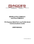
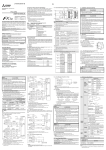
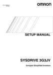
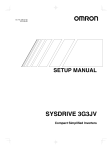
10623 Roselle Street, San Diego, CA 92121 • (858) 550-9559 • FAX (858) 550-7322
[email protected] • www.accesio.com
MODEL
PCI-IDO-XX SERIES
USER MANUAL
FILE: MPCI-IDO-xx.A1j
Notice
The information in this document is provided for reference only. ACCES does not assume any liability arising
out of the application or use of the information or products described herein. This document may contain or
reference information and products protected by copyrights or patents and does not convey any license under
the patent rights of ACCES, nor the rights of others.
IBM PC, PC/XT, and PC/AT are registered trademarks of the International Business Machines Corporation.
Printed in USA. Copyright 2001, 2005 by ACCES I/O Products Inc, 10623 Roselle Street, San Diego, CA
92121. All rights reserved.
WARNING!!
ALWAYS CONNECT AND DISCONNECT YOUR FIELD CABLING WITH
THE COMPUTER POWER OFF. ALWAYS TURN COMPUTER POWER OFF
BEFORE INSTALLING A CARD. CONNECTING AND DISCONNECTING
CABLES, OR INSTALLING CARDS INTO A SYSTEM WITH THE
COMPUTER OR FIELD POWER ON MAY CAUSE DAMAGE TO THE I/O
CARD AND WILL VOID ALL WARRANTIES, IMPLIED OR EXPRESSED.
2
Manual PCI-IDO-XX Series
Warranty
Prior to shipment, ACCES equipment is thoroughly inspected and tested to applicable specifications.
However, should equipment failure occur, ACCES assures its customers that prompt service and support will
be available. All equipment originally manufactured by ACCES which is found to be defective will be repaired
or replaced subject to the following considerations.
Terms and Conditions
If a unit is suspected of failure, contact ACCES' Customer Service department. Be prepared to give the unit
model number, serial number, and a description of the failure symptom(s). We may suggest some simple
tests to confirm the failure. We will assign a Return Material Authorization (RMA) number which must appear
on the outer label of the return package. All units/components should be properly packed for handling and
returned with freight prepaid to the ACCES designated Service Center, and will be returned to the
customer's/user's site freight prepaid and invoiced.
Coverage
First Three Years: Returned unit/part will be repaired and/or replaced at ACCES option with no charge for
labor or parts not excluded by warranty. Warranty commences with equipment shipment.
Following Years: Throughout your equipment's lifetime, ACCES stands ready to provide on-site or in-plant
service at reasonable rates similar to those of other manufacturers in the industry.
Equipment Not Manufactured by ACCES
Equipment provided but not manufactured by ACCES is warranted and will be repaired according to the terms
and conditions of the respective equipment manufacturer's warranty.
General
Under this Warranty, liability of ACCES is limited to replacing, repairing or issuing credit (at ACCES
discretion) for any products which are proved to be defective during the warranty period. In no case is ACCES
liable for consequential or special damage arriving from use or misuse of our product. The customer is
responsible for all charges caused by modifications or additions to ACCES equipment not approved in writing
by ACCES or, if in ACCES opinion the equipment has been subjected to abnormal use. "Abnormal use" for
purposes of this warranty is defined as any use to which the equipment is exposed other than that use
specified or intended as evidenced by purchase or sales representation. Other than the above, no other
warranty, expressed or implied, shall apply to any and all such equipment furnished or sold by ACCES.
3
Manual PCI-IDO-XX Series
Table of Contents
Chapter 1: Introduction...................................................................................................... 5
Figure 1-1: Block Diagram......................................................................................................................... 7
Chapter 2: Installation........................................................................................................ 8
Chapter 3: Option Selection ............................................................................................ 10
Figure 3-1: Option Selection Map............................................................................................................ 10
Chapter 4: Address Selection ......................................................................................... 11
Chapter 5: Programming ................................................................................................. 12
Chapter 6: Connector Pin Assignments......................................................................... 13
Table 6-1: Connector Pin Assignments ................................................................................................... 13
4
Manual PCI-IDO-XX Series
Chapter 1: Introduction
Features
•
•
•
•
•
•
•
Individually-Isolated Digital Outputs for up to three 16-bit groups
Output readback
All solid-state design permits higher throughput than possible with electromechanical relays
Load voltages up to 60 V
Outputs at zero volts at power turn-on and computer reset
Output connectors via on-card ribbon-cable headers
Lower cost per point than externally-racked solid-state relay modules
Description
This series of cards provide 16, 32, or 48 opto-isolated differential outputs. Solid-state, P-Channel FET
switches are used as the output elements and provide both greater reliability and much faster turn-on and
turn-off time than is possible with electromechanical relays. User-supplied load voltages can be from 5V to
60V.
Output connections are via 50-wire ribbon cables that mate with headers on the card. A strain relief bar where
the cables exit the card assures that the cables will not interfere with adjacent cards. Standard cables are six
feet long but alternate lengths are available.
The card uses six bytes of I/O bus address, one byte for each of eight bits of output. The logic on the chip
allows the application to read what was written to the latches. Diodes are included across the load for
inductive-spike protection. There are 48-bit, 32-bit and 16-bit versions. The latter two models are depopulated
versions of the 48-bit card.
Outputs
•
•
•
Number of Channels:
Load Voltage Range:
Load Current per Channel:
•
•
Isolation:
Switching Time:
•
•
•
Switch Resistance:
Switch Leakage Current:
Power Required
16, 32, or 48
5V to 60V (Voltage supplied by User)
1A max. steady state, 2A pulse (Note: Current may be limited by
the cable. Certain ribbon cables limit current to 0.5A.)
On-Card Channel-to-channel and channel-to-computer (* see note)
Turn-On 50μs
Turn-Off 5μs, inductive-spike protection via a diode
0.4Ω when saturated
100 to 300μA
+5 VDC @ 245mA (48 bits)
*Note on Isolation: Opto-Isolators and connectors are rated for at least 500V, but isolation voltage
breakdowns will vary and are affected by factors like cabling, spacing of pins, spacing between traces on the
PCB, humidity, dust and other environmental factors. This is a safety issue so a careful approach is required.
For CE certification, isolation was specified at 60V DC. The design intention was to eliminate the influence of
common mode. Use proper wiring techniques to minimize voltage between channels and to ground.
Tolerance of higher isolation voltage can be obtained on request by applying a conformal coating to the
board.
5
Manual PCI-IDO-XX Series
Environmental
•
•
•
•
Operating Temperature Range:
Storage Temperature Range:
Humidity:
Board Dimensions:
0°C to +70°C
-40°C to +150°C
5% to 90% RH, non-condensing
6.875" (174.6mm) long
Each bit of the card is optically-isolated from the output driver which switches the supply voltage to the output
pin. The negative connection is made on the return pin and each output is isolated from every other output.
When the opto-isolator is OFF the FET is activated by the Zener-diode-limited supply voltage. When the FET
is activated, the full Supply voltage is available at the output pin. When the opto-isolator is ON, the FET
deactivates and the output drops to the return line voltage level. Diodes are included across the load for
inductive-spike protection.
Safety Note
These cards are used mostly as switches for externally supplied power up to 60VDC and up to one Amp. If
the computer is turned OFF and that external power is still applied to the card, all the output lines will be
turned ON. To avoid damage or injury, you MUST turn OFF the external power when the computer is turned
OFF.
6
Manual PCI-IDO-XX Series
Figure 1-1: Block Diagram
7
Manual PCI-IDO-XX Series
Chapter 2: Installation
A printed Quick-Start Guide (QSG) is packed with the card for your convenience. If you’ve already performed
the steps from the QSG, you may find this chapter to be redundant and may skip forward to begin developing
your application.
The software provided with this card is on CD and must be installed onto your hard disk prior to use. To do
this, perform the following steps as appropriate for your operating system.
CD Software Installation
The following instructions assume the CD-ROM drive is drive “D”. Please substitute the appropriate drive
letter for your system as necessary.
DOS
1.
2.
3.
4.
Place the CD into your CD-ROM drive.
Type B- to change the active drive to the CD-ROM drive.
Type GLQR?JJ- to run the install program.
Follow the on-screen prompts to install the software for this board.
WINDOWS
1.
Place the CD into your CD-ROM drive.
2.
The system should automatically run the install program. If the install program does not run promptly,
click START | RUN and type BGLQR?JJ, click OK or press -.
3.
Follow the on-screen prompts to install the software for this board.
LINUX
1.
Please refer to linux.htm on the CD-ROM for information on installing under linux.
Caution! * ESD A single static discharge can damage your card and cause premature failure!
Please follow all reasonable precautions to prevent a static discharge
such as grounding yourself by touching any grounded surface prior to
touching the card.
8
Manual PCI-IDO-XX Series
Hardware Installation
1.
2.
3.
4.
5.
6.
7.
8.
9.
Do not install card into the computer until the software has been fully installed.
Turn OFF computer power AND unplug AC power from the system.
Remove the computer cover.
Carefully install the card in an available 5V or 3.3V PCI expansion slot (you may need to remove a
backplate first).
Inspect for proper fit of the card and tighten screws. Make sure that the card mounting bracket is
properly screwed into place and that there is a positive chassis ground.
Install an I/O cable onto the card’s bracket mounted connector.
Replace the computer cover and turn ON the computer which should auto-detect the card (depending
on the operating system) and automatically finish installing the drivers.
Run PCIfind.exe to complete installing the card into the registry (for Windows only) and to determine
the assigned resources.
Run one of the provided sample programs that was copied to the newly created card directory (from
the CD) to test and validate your installation.
The base address assigned by BIOS or the operating system can change each time new hardware is
installed into or removed from the computer. Please recheck PCIFind or Device Manager if the
hardware configuration is changed. Software you write can automatically determine the base
address of the card using a variety of methods depending on the operating system. In DOS, the
PCI\SOURCE directory shows the BIOS calls used to determine the address and IRQ assigned to
installed PCI devices. In Windows, the Windows sample programs demonstrate querying the registry
entries (created by PCIFind and NTIOPCI.SYS during boot-up) to determine this same information.
9
Manual PCI-IDO-XX Series
Chapter 3: Option Selection
There are no user configurable options on this product.
3.90"
6.90"
Figure 3-1: Option Selection Map
10
Manual PCI-IDO-XX Series
Chapter 4: Address Selection
This card uses I/O addresses offset from the base address assigned by the PCI bus. The address spaces are
defined in the Programming section of this manual.
PCI architecture is Plug-and-Play. This means that the BIOS or Operating System determines the resources
assigned to PCI cards rather than the user selecting these resources with switches or jumpers. As a result,
you cannot set or change the card’s base address or IRQ level. You can only determine what the system has
assigned.
To determine the base address that has been assigned, run the PCIFind utility program. This utility will
display a list of all the cards detected on the PCI bus, the addresses assigned to each function on each of the
cards, and the respective IRQs.
Alternatively, Windows systems can be queried to determine which resources were assigned. In these
operating systems, you can use either PCIFind, or the Device Manager utility from the System Properties
applet of the control panel. The card is installed in the Data Acquisition class of the Device Manager list.
Selecting the card, clicking Properties, and then selecting the Resources Tab will display a list of the
resources allocated to the card.
The PCI bus supports 64K of I/O address space, so your card’s addresses may be located anywhere in the
0000h to FFFFh range. The card occupies eight consecutive 8 bit registers in the I/O address space.
PCIFind uses the Vendor ID and Device ID to search for your card, then reads the base address and IRQ. If
you want to determine the base address and IRQ without using PCIFind, use the following information:
The Vendor ID code is 494F (ASCII for “I/O”)
The Device ID code for the card is 0520
An example of how to locate PCI card resources is provided in the PCI/SOURCE directory, under your
installation directory. This code runs in DOS, and uses the PCI defined interrupt BIOS calls to query the PCI
bus for card-specific information. You will need the Device ID and Vendor ID listed above to use this code.
11
Manual PCI-IDO-XX Series
Chapter 5: Programming
The base address is assigned by the computer system during installation and will fall on an eight-byte
boundary. The card’s read and write functions are as follows:
Address
Write
Read
Base Address +0
Port 0 Bits 0-7
Port 0 Bits 0-7
Base Address +1
Port 0 Bits 8-15
Port 0 Bits 8-15
Base Address +2
Port 1 Bits 0-7
Port 1 Bits 0-7
Base Address +3
Unused
Unused
Base Address +4
Port 1 Bits 8-15
Port 1 Bits 8-15
Base Address +5
Port 2 Bits 0-7
Port 2 Bits 0-7
Base Address +6
Port 2 Bits 8-15
Port 2 Bits 8-15
Base Address +7
Unused
Unused
Writing a byte to Port n address activates each output with a “1” at the bit location, deactivates each output
with a “0” at the bit.
Reading a byte from Port n address displays a “1” for each output that is active, and displays a “0” for each
output that is inactive.
Bit 7/15
D7
Bit 6/14
D6
Bit 5/13
D5
Bit 4/12
D4
Bit 3/11
D3
12
Bit 2/10
D2
Bit 1/9
D1
Bit 0/8
D0
Manual PCI-IDO-XX Series
Chapter 6: Connector Pin Assignments
Three identical 50-pin headers are provided on the product; one for each 16-bit output group. Port 0 is near
the mounting bracket while Port 2 is at the far end of the card. Connector pin assignments are listed below.
Pin
Signal
Pin
Signal
1
Ground
2
Bit 0 Return
3
Bit 0 Out
4
Bit 0 Supply
5
Bit 1 Return
6
Bit 1 Out
7
Bit 1 Supply
8
Bit 2 Return
9
Bit 2 Out
10
Bit 2 Supply
11
Bit 3 Return
12
Bit 3 Out
13
Bit 3 Supply
14
Bit 4 Return
15
Bit 4 Out
16
Bit 4 Supply
17
Bit 5 Return
18
Bit 5 Out
19
Bit 5 Supply
20
Bit 6 Return
21
Bit 6 Out
22
Bit 6 Supply
23
Bit 7 Return
24
Bit 7 Out
25
Bit 7 Supply
26
Bit 8 Return
27
Bit 8 Out
28
Bit 8 Supply
29
Bit 9 Return
30
Bit 9 Out
31
Bit 9 Supply
32
Bit 10 Return
33
Bit 10 Out
34
Bit 10 Supply
35
Bit 11 Return
36
Bit 11 Out
37
Bit 11 Supply
38
Bit 12 Return
39
Bit 12 Out
40
Bit 12 Supply
41
Bit 13 Return
42
Bit 13 Out
43
Bit 13 Supply
44
Bit 14 Return
45
Bit 14 Out
46
Bit 14 Supply
47
Bit 15 Return
48
Bit 15 Out
49
Bit 15 Supply
50
Ground
Table 6-1: Connector Pin Assignments
13
Manual PCI-IDO-XX Series
Customer Comments
If you experience any problems with this manual or just want to give us some feedback, please email us at:
[email protected]. Please detail any errors you find and include your mailing address so that we can
send you any manual updates.
10623 Roselle Street, San Diego CA 92121
Tel. (858)550-9559 FAX (858)550-7322
www.accesio.com
14
Manual PCI-IDO-XX Series