1
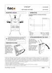
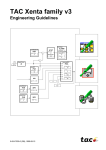
AH02: West
_STATUS
TEMPERATURES
ALARMS
®
TAC Xenta OP
Handbook
0-004-7506-4 (EN), 2001-08-08
TAC Xenta OP Handbook
Foreword
Foreword
Welcome to the manual of TAC Xenta OP, version VMX 3.2 and
higher.
Should you discover errors and/or unclear descriptions in this manual,
please contact your TAC representative.
You may also want to send an e-mail to [email protected].
This edition, -4, applies to TAC Xenta OP version VMX 3.2 or later.
The procedure for de-installation of the OP has been clarified and put
in a separate section, 2.7.
The possibility to select which unit system (SI or US Imperial) is used,
when connecting to TAC Xenta 100, is now described in section 3.2.
TAC AB, 2001-08-08
0-004-7506-4 (EN), 3 (36)
TAC Xenta OP Handbook
Foreword
Copyright © 2001 TAC AB.
This document, as well as the product it refers to, is only intended for licensed users of the product and the document.
TAC AB owns the copyright of this document and reserves the right to make changes, additions or deletions.
TAC AB assumes no responsibility for possible mistakes or errors that might appear in this document.
Do not use the product for any other purposes than those indicated in this document.
Only licensed users of the product and the document are permitted to use the document or any information therein.
Distribution, disclosure, copying, storing or use of the product, the information or the illustrations in the document
on the part of non-licensed users, in electronic or mechanical form, as a recording or by other means, including
photocopying or information storage and retrieval systems, without the express written permission of TAC AB, will
be regarded as a violation of copyright laws and is strictly prohibited.
TAC Xenta®, TAC Menta® and TAC Vista® are registered trademarks of TAC AB in Sweden and other countries.
All other brand names are trade marks of their respective owners.
Revisions list
Art no
Comments
Editor
Date
0-004-7506-0
First version.
KW
1996-08-08
0-004-7506-1
This document has been revised to cover TAC Xenta v 3.0.
KW
1997-09-01
Trade mark change from TA to TAC.
KW
1998-06-11
0-004-7506-2
This document has been revised to cover TAC Xenta v 3.2.
KW
1999-01-26
0-004-7506-3
The explanation of the OP communication mode has been
expanded (section 2.6).
KW
2000-08-08
KW
2001-08-08
The following major changes have been made:
- The Chapter contents have been rearranged.
- A new chapter has been added, showing how to communicate
with Xenta 100 and how to reach the Network Variables.
The OP/RU model with Cyrillic characters added.
0-004-7506-4
The de-installation procedure has been clarified (section 2.7).
Switching between SI and I-P units has been added to section 3.2.
4 (36), 0-004-7506-4 (EN)
TAC AB, 2001-08-08
TAC Xenta OP Handbook
Contents
TAC Xenta OP
Handbook
Subject to modification.
Contents
1
1.1
1.2
1.3
2
2.1
2.2
2.3
2.4
2.5
2.6
2.7
2.7.1
2.7.2
3
3.1
3.2
3.3
3.4
3.5
4
4.1
4.2
4.3
4.4
4.5
4.6
4.7
4.8
4.9
Introduction .................................................................................................................... 7
TAC Xenta OP ....................................................................................................................................... 7
This manual ............................................................................................................................................7
More information .................................................................................................................................. 8
Connection and Basic Functions ................................................................................... 9
Description ............................................................................................................................................. 9
Connecting to TAC Xenta 100 ........................................................................................................... 10
Connecting to TAC Xenta 300/401 .................................................................................................... 11
Keys ...................................................................................................................................................... 12
Local functions of the OP Service menu ........................................................................................... 13
Selecting the OP communication mode ............................................................................................ 15
De-installing the OP ........................................................................................................................... 17
Tool: MetraVision ................................................................................................................................. 17
Tool: LonMaker .................................................................................................................................... 18
Dialogs with TAC Xenta 100........................................................................................ 19
General ................................................................................................................................................
Connecting to TAC Xenta 100 ...........................................................................................................
Setting the Node state in TAC Xenta 100 ..........................................................................................
Reading/checking NVs in TAC Xenta 100 ........................................................................................
Initiate Service pin message ...............................................................................................................
19
19
21
21
22
Dialogs with TAC Xenta 300 and 401 ......................................................................... 23
The menus ...........................................................................................................................................
Find and change a setpoint ................................................................................................................
View/acknowledge alarms ..................................................................................................................
Change the Time channels .................................................................................................................
Access Code .........................................................................................................................................
Edit access code ...................................................................................................................................
Overriding inputs/outputs..................................................................................................................
Daylight saving ....................................................................................................................................
Log off ..................................................................................................................................................
TAC AB, 2001-08-08
23
24
25
26
28
29
29
30
30
0-004-7506-4 (EN), 5 (36)
TAC Xenta OP Handbook
5
Contents
Technical data ............................................................................................................... 31
Index ....................................................................................................................................... 33
This manual contains a total of 36 pages.
6 (36), 0-004-7506-4 (EN)
TAC AB, 2001-08-08
TAC Xenta OP Handbook
1
1 Introduction
Introduction
1.1 TAC Xenta OP
TAC Xenta OP is a small operator panel designed to be used together
with TAC Xenta 100, 300, 401 and 901 units.
The operator panel gives the user access to parameters and alarms
without communicating with a central system. Additionally, it is used
to monitor status, adjust setpoints and time channels. All values are
displayed with an explanatory text in the alphanumeric display window.
Please note!
The TAC Xenta OP and the other products of the Xenta family must
not be used for any other purpose than that for which it was designed.
Installation and repair may only be performed by authorized personnel.
1.2 This manual
This handbook has the following contents:
Chapter 2
In this chapter the connection of the operator panel, TAC Xenta OP,
to the TAC Xenta 100 and TAC Xenta 300/401 controllers is shown.
Chapter 3
The use of the OP together with TAC Xenta 100 and the principles for
handling display of Network Variables are explained in this chapter.
Chapter 4
The use of the OP together with TAC Xenta 300/401 controllers and
the most common menus are discussed here
TAC AB, 2001-08-08
0-004-7506-4 (EN), 7 (36)
TAC Xenta OP Handbook
1 Introduction
Chapter 5
This chapter contains technical data on the TAC Xenta OP.
1.3 More information
TAC Xenta OP is also described or mentioned in the following
documents:
• the TAC Xenta OP Operator panel data sheet (C-98-05)
• the handbooks for the different TAC Xenta controller units
• the “TAC Menta User’s manual”
Stand-alone TAC Xenta 300/3000 controllers and I/O modules can be
commissioned by using the Service menu of TAC Xenta OP (which is
not the same as the local OP service menu). This procedure is described in the TAC Xenta 300 and 401 Handbook.
8 (36), 0-004-7506-4 (EN)
TAC AB, 2001-08-08
TAC Xenta OP Handbook
2
2 Connection and Basic Functions
Connection and Basic Functions
2.1 Description
The TAC Xenta OP Operator panel has an LCD display with 4*20
characters and six push buttons. A modular socket or four screw
terminals are used for communication and for connecting the power
supply. These connectors are placed on the rear. There is also a
potentiometer to adjust the contrast of the display, on the rear.
The OP has an LCD display that can be lighted from beneath. The
light is controlled from the OP Service menu (section 2.5).
LCD display
–
Connectors
(rear)
+
Push buttons
The TAC Xenta OP operator panel
The operator panel is used to monitor status and to adjust setpoints
and time channels. It also makes it possible to list the alarms without
communicating with a central system.
The operator panel is controlled from a master, a TAC Xenta 100, 300
or 401 controller. When you start using the operator panel, it will send
a message to the master telling it what button was pushed. The master
contains the dialogue messages and will direct the operator panel what
to show on the display. Thus the operator panel will act as a dumb
terminal.
TAC AB, 2001-08-08
0-004-7506-4 (EN), 9 (36)
TAC Xenta OP Handbook
2 Connection and Basic Functions
2.2 Connecting to TAC Xenta 100
Normally the TAC Xenta OP is connected to the modular jack on the
lower side of the Wall Module. In this way the Xenta OP will get
power supply from the TAC Xenta 100 unit.
Cable between controller and Operator panel ...................... max. 10 m
TAC Xenta 100
Wall Module
COMFORT
ECONOMY
OFF
Connecting the TAC Xenta OP to TAC Xenta 100 via the Wall Module
The contrast of the display can be adjusted with the potentiometer on
the rear of the operator panel; please refer to the figure in the next
section.
10 (36), 0-004-7506-4 (EN)
TAC AB, 2001-08-08
TAC Xenta OP Handbook
2 Connection and Basic Functions
2.3 Connecting to TAC Xenta 300/401
Cable between controller and Operator panel...................... max. 10 m
When connecting the operator panel there are two alternatives (please
refer to the adjacent figures):
• Use the modular socket on the front of the TAC Xenta 300 or 401
controller and the corresponding socket on the back of the operator
panel. This requires a special cable.
• Use the screw terminals on the back of the operator panel, labelled 1–4. Terminals 1 and 2 are used for communication and
terminals 3 and 4 for 24 V AC (or DC).
At the controller you use the terminals C1, C2 and G, G0.
TAC Xenta 300/401
controller
Socket for
connection to the
operator panel
Socket and screw terminals for
the TAC Xenta controller
connection
Contrast
adjustment
(on the rear)
1 2 3 4
C1 C2 G G0
Service pin
Modular socket
on the OP
TAC Xenta OP connectors and contrast potentiometer
The contrast of the display can be adjusted with the potentiometer on
the rear of the operator panel.
(The Service pin is available from the rear if, in special cases, the
network configuration procedure requires this. When the pin is
pressed, a unique hardware identity code is sent on the network.)
TAC AB, 2001-08-08
0-004-7506-4 (EN), 11 (36)
TAC Xenta OP Handbook
2 Connection and Basic Functions
2.4 Keys
The TAC Xenta OP keys:
–
+
is used to step up one level in the directory hierarchy
(“Home”). There may be several levels in the hierarchy. The
cursor will return to the line selected the last time this level
was active. This button does not by itself make changes
effective.
–
is used to decrease values. If this button is kept depressed,
the stepping speed increases.
+
is used to increase values. If this button is kept depressed,
the stepping speed increases.
is used to move the cursor upwards in a menu list or to move
to previous alarm or logged record.
is used to move the cursor downwards in a menu list or to
move to previous alarm or logged record.
is used to select a line, indicated by the cursor (“Enter”) or
to move between the different adjustable values.
This button also makes changes effective.
12 (36), 0-004-7506-4 (EN)
TAC AB, 2001-08-08
TAC Xenta OP Handbook
2 Connection and Basic Functions
2.5 Local functions of the OP Service menu
For simple hardware check of the OP and for certain system parameters there is a local Service menu in the operator panel. The OP
functions are quite independent of the other TAC Xenta units and only
require that the operator panel is connected to the network and that the
panel has not been set in the TAC Xenta 100 communication mode
(see below).
. and
The Service menu appears if both the keys
pressed for about three seconds simultaneously.
are
OP Service menu
1. Exit service mode
2. Keyboard test
3. Display test
4. LON address
5. National text
6. SW version
7. LonTalk status
8. Display backlight
9. Service pin
10. OP mode
Select the required function and press
.
Two hardware tests
2. Keyboard test
is a simple test of the keyboard functions:
*
*
* *
*
*
Keyboard test
Press keys!
Double-press
for QUIT
Each asterisk corresponds to a key. Double pressing on any key means
leaving the test.
3. Display test
will test all display positions in a number of steps.
Each step is initiated by pressing any key.
System information
4. LON address
6. SW version
7. LonTalk status
9. Service pin
TAC AB, 2001-08-08
shows the current Domain/Subnet/Node address for the operator
panel.
lists the current version of the operator panel version and
shows statistics from the network communication.
is a way to send the unique Neuron ID on the network.
Mainly used for testing purposes.
0-004-7506-4 (EN), 13 (36)
TAC Xenta OP Handbook
2 Connection and Basic Functions
Selecting the language of the OP messages
5. National text
means that the operator can switch between different languages for
those messages that are generated in the OP.
Select language
No reply ...
Wait ...
Press Enter to save!
If you press
German:
or
the language will change, for example into
Select language
Keine Antwort ...
Bitte warten ...
Press Enter to save!
When you have selected a suitable language you press
(“Enter”) and then leave the menu.
Controlling the display light
8. Display backlight controls the background light of the OP display.
There are three modes: OFF, ON and AUTO.
OFF
means that the backlight is always turned off,
ON
means that the light is turned on permanently and
AUTO means that the light is turned on as soon as a button is
pressed, but goes off about 30 minutes after the last key has been
pressed.
Use
+ and –
to select the required mode.
As the display light may cause loss of contrast if turned on permanently, we recommend the AUTO or OFF mode.
Leaving the OP Service menu
1. Exit service mode means leaving the local OP service menu.
This will also happen if no key has been used during about 40 seconds.
Selecting the OP mode
10. OP mode
In TAC Xenta networks the OP may work in one of two
communication modes:
- for communication with Base units, TAC Xenta 300 and 400
- for communication with TAC Xenta 100
Furthermore, the OP can be more or less mobile, depending on the
way the OP is connected to the network.
Please refer to the next section!
14 (36), 0-004-7506-4 (EN)
TAC AB, 2001-08-08
TAC Xenta OP Handbook
2 Connection and Basic Functions
2.6 Selecting the OP communication mode
Xenta 100: ON/OFF
When delivered, the OP is set for Base unit (TAC Xenta 300, 400)
communication. To change the communication mode, you have to call
up the OP Service menu and go to the 10.OP mode menu, where the
TAC Xenta 100 mode can be turned on/off.
Change OP mode
Xenta 100 : OFF
Bindable
: TAC
Use
+ or –
to change the Xenta 100 mode and press
.
When the OP is set to allow the Xenta 100 mode, the operator is given
a choice to access TAC Xenta 100 (in stead of TAC Xenta 300/400)
by pressing “Enter”, each time an OP is connected.
The OP Service menu cannot be reached when the OP is in the Xenta
100 mode.
If you want to turn OFF the Xenta 100 mode, once you are in this
mode, you must temporarily disconnect the OP and let the OP revert to
the Base unit communication mode in order to be able to reach the
Service menu and from there select the 10. Change OP mode
menu.
The TAC Xenta 100 OP communication is described in the next chapter.
“Bindable” is explained after the Summary below.
Summary
To turn ON the Xenta 100 mode
Connecting to
Xenta Base unit
OP Service menu
1. Exit service mode
2. Keyboard test
3. Display test
.
10 OP mode
Change OP mode
Xenta 100 : ON
Bindable
: TAC
1 Connect the OP and wait for message on display.
2 Press both keys
simultaneously.
. and
for about three seconds
3 Select 10.OP mode menu.
+ or –
4 Press
to set the Xenta 100 mode ON and press
.
Press enter to
access Xenta 100
Connecting to
Xenta 100 ...
5 Temporarily disconnect the OP and wait for message on display.
6 Press
to access Xenta 100.
7 Wait for message on display.
TAC AB, 2001-08-08
0-004-7506-4 (EN), 15 (36)
TAC Xenta OP Handbook
2 Connection and Basic Functions
To turn OFF the Xenta 100 mode
Press enter to
access Xenta 100
(wait)
Connecting to
Xenta Base unit
OP Service menu
1. Exit service mode
2. Keyboard test
3. Display test
.
10 OP mode
1 (Disconnect and then) connect the OP; wait for a couple of
seconds for the Base unit message to appear.
2 Press both keys
simultaneously.
. and
for about three seconds
3 Select 10.OP mode menu.
+ or –
Change OP mode
Xenta 100 : OFF
Bindable
: TAC
4 Press
1. Exit service mode
5 Select the 1.Exit service mode menu and press
Bindable
press
to set the Xenta 100 mode OFF and
.
.
“Bindable” is a LonWorks term, describing how the OP is connected
and addressed in the network. This, in turn, affects the mobility of the
OP.
Use
+ or –
• TAC
to select Bindable mode from the following.
OP movable. Two available addresses following each
TAC Xenta Base unit.
• INST OP permanently electrically connected to the network;
installed with a binding tool.
• MAN
OP movable, the domain ID of the network has to be
programmed via OP Service menu – 4.LON address
(communication is here limited to Base units on the same
channel).
For OP version 3.11 and earlier the following modes can be chosen.
• OFF
OP movable. Two available addresses following each
TAC Xenta Base unit.
• ON
OP permanently electrically connected to the network;
installed with a binding tool.
Confirm your choice by pressing
16 (36), 0-004-7506-4 (EN)
.
TAC AB, 2001-08-08
TAC Xenta OP Handbook
2 Connection and Basic Functions
2.7 De-installing the OP
If the OP is to be de-installed from the network, it should be restored
to the original factory setting to avoid problems, if used in another
network.
Depending on which binding tool has been used, the de-installation is
made according to one of the methods shown below.
2.7.1 Tool: MetraVision
1 Select OP Service menu – 10. OP mode and set
Bindable to “TAC” or, in OP version < 3.11, ”OFF”.
2 Disconnect the OP electrically from the network.
3 “Remove” the OP node from the data base.
Factory setting
A
If the OP has been labelled ”Unconfig”, which may happen if step 3
above was executed before step 2, or for any other reason; the OP may
be restored to the factory setting in one of two ways:
Reconnect the OP to the network, reinstall it and perform the steps
above in the correct order,
or,
B
use the Nodutil program and do the following.
1 Select OP Service menu – 10. OP mode and set
Bindable to “TAC” or, in OP version < 3.11, “OFF”.
2 Start Nodutil.
3 Press the Service pin of the OP.
4 Type “G”.
5 Type “1”, press Enter.
6 Type “M”.
7 Type “S”.
8 Type “C”.
TAC AB, 2001-08-08
0-004-7506-4 (EN), 17 (36)
TAC Xenta OP Handbook
2 Connection and Basic Functions
2.7.2 Tool: LonMaker
1 Check in the OP Service menu – 10. OP mode that
Bindable is set to “TAC” or, in OP version < 3.11 to “OFF”.
2 Start the LonMaker Browser.
3 Click right, choose Properties.
Restore SNVT_config_src from cfg_external (1) to cfg_local (0).
SNVT_config_src is called var_2 in the Browser.
Please note!
4 Disconnect the OP electrically from the network.
5 Remove the OP from the data base of LonMaker.
Factory setting
A
If the OP has been de-installed in an incorrect way, it may be restored
to the factory setting in one of two ways:
Reconnect the OP to the network, reinstall it and perform the steps
above in the correct order,
or,
B
use the Nodutil program and perform the following.
1 Select OP Service menu – 10. OP mode and set
Bindable to “TAC” or, in OP version < 3.11, “OFF”.
2 Start Nodutil.
3 Press the Service pin of the OP.
4 Type “G”.
5 Type “1”, press Enter.
6 Type “M”.
7 Type “S”.
8 Type “C”.
9 Type “U”.
10 Type “2”, press Enter.
11 Type “00”, press Enter.
18 (36), 0-004-7506-4 (EN)
TAC AB, 2001-08-08
TAC Xenta OP Handbook
3
3 Dialogs with TAC Xenta 100
Dialogs with TAC Xenta 100
3.1 General
TAC Xenta OP can be used as a service and limited commissioning
tool for the TAC Xenta 100 Zone Controllers. These controllers use
Network Variables of the LonWorks standard type (“SNVT”, Standard
Network Variable Type) for all data communication on the network.
All Network Variables, including the configuration parameters can be
accessed via the keypad and the LCD display.
In order to separate this general kind of communication from the
dedicated communication used with TAC Xenta 300 and 401 controllers, the TAC Xenta OP has two different communication modes.
3.2 Connecting to TAC Xenta 100
Note!
The very first time a TAC Xenta OP is connected to a Xenta network,
the TAC Xenta 100 communication mode is, by default, in the Off
state. Please refer to the end of chapter 2 for the necessary procedures
to change the communication mode. When this has been done, the
operator is given a choice to access TAC Xenta 100 (in stead of the
Base units, TAC Xenta 300 or 401):
Press enter to
access Xenta 100
Press the key
to get the display
Connecting to
Xenta 100 ...
Check that the LED on the Wall Module will flash for some 10
seconds or that the red Service LED turns on and then off after a
couple of seconds, on the connected controller.
If contact is established without the LED flashing, Xenta OP has
connected to another node in the network. In this case disconnect
Xenta OP and then reconnect.
TAC AB, 2001-08-08
0-004-7506-4 (EN), 19 (36)
TAC Xenta OP Handbook
3 Dialogs with TAC Xenta 100
Wait for the display
Xenta 100 is:
Configured
Press <DOWN> to
continue
Press the key
and wait for a display looking like:
Xenta 103v1.00-10
103/A/v10003
units as SI [^]
NV index? 000
The first two lines, showing software versions, are displayed the first
time only.
The third line shows which unit system is used, when SNVT values
are presented in the OP menus.
The
key toggles between SI (metric) and US Imperial
(Inch-Pound) units.
From this display (normally only lines 3-4 appear) the different
Network Variables can be selected.
20 (36), 0-004-7506-4 (EN)
TAC AB, 2001-08-08
TAC Xenta OP Handbook
3 Dialogs with TAC Xenta 100
3.3 Setting the Node state in TAC Xenta 100
When the display
Xenta 100 is:
Configured
Press <DOWN> to
continue
is shown, the second line can be switched between Configured and
Unconfigured, using the + and –
keys.
When Configured the TAC Xenta 100 can send and receive Network
Variables.
When Unconfigured the TAC Xenta 100 cannot communicate on the
network.
In normal operation on a network, the TAC Xenta 100 should always
be set to Configured.
Configured/Unconfigured are normally set by a binding tool, in a
network configuration and by TAC Xenta OP in a stand-alone
configuration. See also the TAC Xenta Network guide.
3.4 Reading/checking NVs in TAC Xenta 100
When connection has been established (section 3.2) a NV (Network
Variable) index can be selected by the use of the + and –
keys.
Keep the key pressed to increase the toggling speed. Press the
key to display the selected variable.
Example: Select NV 004 to get the Effective Setpoint:
4 nvoEffectSetpt
21.00 °C
nvo indicates that this is an output value and cannot be changed
from the OP.
Use the key
TAC AB, 2001-08-08
to return to NV index selection.
0-004-7506-4 (EN), 21 (36)
TAC Xenta OP Handbook
3 Dialogs with TAC Xenta 100
Input variables appear further down in the list:
Example: Select NV 013 to get the Application Mode:
13 nviApplicMode
Auto
_
nvi indicates that this is an input value. The cursor is visible and
allows the value to be changed from the OP.
Use
+
–
and
to change the value. Keep the key pressed to
increase the toggling speed.
Press
If
to enter the new value.
or
or
is pressed before
, no change will
take place.
The keys
list.
and
will take you to the adjoining NVs in the
3.5 Initiate Service pin message
When the NV index selection is displayed
units as SI [^]
NV index? 000
a Service pin message is sent from the Xenta 100, initiated from the
OP, each time the
22 (36), 0-004-7506-4 (EN)
key is pressed.
TAC AB, 2001-08-08
TAC Xenta OP Handbook
4
4 Dialogs with TAC Xenta 300 and 401
Dialogs with TAC Xenta 300 and 401
4.1 The menus
The menus of the operator panel and the order in which they are
presented are designed by an application programmer, using the
TAC Menta design tool.
Thus, the menus shown below are only examples. The principles
showing how to select among the menus and how to change the values
are, however, general.
Cyrillic characters
The TAC Xenta OP/RU model has the capability of displaying
Cyrillic characters.
The TAC Menta User’s manual describes how you switch the character files of the OP.
24 hour clock vs. AM/PM clock
In those menus that allow time (clock) entries, like the Time Schedule, the Holiday chart (Time channels) and the Daylight saving
menus, you may choose to present time with a 24 hour clock or with a
12 hour clock, also called an AM/PM clock. The choice is made
already during the menu design phase in TAC Menta.
To translate between the two modes of display the following table can
be used.
24 hour
clock
AM/PM
clock
01.00
06.00
11.59
12.00
12.59
13.00
18.00
23.59
00.00
00.59
01.00 AM
06.00 AM
11.59 AM
12.00 PM
12.59 PM
01.00 PM
06.00 PM
11.59 PM
12.00 AM
12.59 AM
When the AM/PM clock is used, the time in the OP menus are
compressed to hhAmm and hhPmm for hh.mm AM and hh.mm PM
respectively.
TAC AB, 2001-08-08
0-004-7506-4 (EN), 23 (36)
TAC Xenta OP Handbook
4 Dialogs with TAC Xenta 300 and 401
4.2 Find and change a setpoint
This example starts with the first screen showing all TAC Xenta 300/
401 controllers in the network and shows how to find and change the
supply air setpoint in “AH02 West”:
AH01 East
AH02 West
HEAT-1 North
HEAT-2 South
Press
once and then
AH02: West
_STATUS
TEMPERATURES
ALARMS
Press
once and then
AH02: Temperatures
Outdoor temp:
Now: 16.5 C
Max:22.5 Min:11.3
Press
until the required screen is found
AH02: Temperatures
Supply air
Measured: 17.1 C
Set value: 27.5 C
As there is only one value that could be changed in this screen the
cursor is already in the right position and the setpoint could be set
with + and – .
Changes will be effective as soon as
24 (36), 0-004-7506-4 (EN)
is pressed.
TAC AB, 2001-08-08
TAC Xenta OP Handbook
4 Dialogs with TAC Xenta 300 and 401
4.3 View/acknowledge alarms
To make the operator aware of unacknowledged alarms in the alarm
list the abbreviated application/base unit name (“AH02” in our examples) will flash. When the item “Alarms” has been found and selected
with Enter, a screen like the following will appear:
AH02
ALARMS: 6/6
P1
PUMP STOPPED
99-JAN-15 14:05 ON
On the top row there is an indication that this is alarm number six of
or
six in the list. To see the other alarms in the list use
.
The text “ON” in the above alarm example indicates that the alarm
has tripped but not been acknowledged.
A selected alarm is acknowledged when the operator presses
(Enter). The text “ON” will change to, for example, “ACK”.
Alarms which have tripped and then returned to normal state are
indicated with “OFF”.
On the Operator panel, for each point at any given moment, at most
one of the three alternatives below can appear:
ON
ON
OFF
ACK
Transitions between these three states at moments in time t1, t2 etc.,
and the disappearance from the list, may occur in the way shown in
the diagram below.
Alarm goes off
Acknowledge
New Alarm
t1 Alarm ON
Alarm goes
off
t2a Alarm ACK
New alarm
----
t3 Alarm ON
Acknowledge
t1 Alarm ON
t2b Alarm OFF
---New alarm
t3 Alarm ON
Possible events at alarms and the way they are presented in the alarm list: time, Alarm text, status
The alarm list is sorted in chronological order with the oldest event
displayed at the top. The alarm list is dimensioned to allow all points
of alarm to appear at the same time.
TAC AB, 2001-08-08
0-004-7506-4 (EN), 25 (36)
TAC Xenta OP Handbook
4 Dialogs with TAC Xenta 300 and 401
If a TAC Xenta controller is connected to a supervisory system like
TAC Vista, another indication may appear in the alarm list. An
asterisk (*) in front of the signal name means that the alarm is
blocked, that is, information about changes between alarm on and
alarm off will not be sent to TAC Vista.
The alarms will, however, be listed on the OP as usual.
The blocking request is set/removed from TAC Vista.
Example:
AH02
ALARMS: 2/6
*SF1
SUPPLY FAN STOPPED
99-JAN-15 13:50 OFF
Note!
Starting with TAC Xenta System program v 3.4 this blocking function
has been changed. The alarm information will be sent to TAC Vista, as
any normal alarm, but it will not be displayed on the OP.
Please note that TAC Vista will store the alarm event in the historical
log, even if alarms of priority 0 are not displayed in the alarm list.
4.4 Change the Time channels
The operating hours for a selected object can be adjusted by altering
one or more time channels. This can be done from the operator panel.
The number of week schedules available for a specific time schedule
is defined in the application program.
The following is an example of an object (AH02) controlled by three
different schedules. The object is active 08:00–12:00 and 13:00–17:00
on weekdays and 08:00–12:00 on Saturdays. The example shows how
to change operating hours on Saturdays to be 08:00–13:30.
Example:
Week schedule
Go to the week schedule for AH02.
AH02: Time schedule
1234567
08:00–12:00 MTWTF
13:00–17:00 MTWTF
26 (36), 0-004-7506-4 (EN)
TAC AB, 2001-08-08
TAC Xenta OP Handbook
4 Dialogs with TAC Xenta 300 and 401
To get to the next schedule controlling AH02 press
once.
AH02: Time schedule
1234567
08:00–12:00
S
As the cursor is positioned under “08”,
must be pressed twice to
move the cursor to “12”. Use + and – to change the off hour to
“13”. Press
once and adjust the minutes.
after the last entry and then use
to
When finished, press
return to the previous menu level.
Holiday chart
The week schedule can be modified by a Holiday chart which defines
conditions for certain dates, for example when Christmas Eve occurs
on a workday:
AH02: Holiday chart
1234567
14:00–17:00 MTWTF
**-12-24 : **-12-24
The asterisks (**) act as “wild card”, that is, the date will in this case
be valid each year.
to
Use + and – to change the time and date values. Use
move the cursor between the fields. To obtain asterisks in the date
fields, toggle the month value past 12. To obtain asterisks for the year
value, you must toggle backwards from the value 94.
after the last entry and then use
When finished, press
return to the previous menu level.
to
The Holiday chart is valid throughout the 24 hours.
Note, for example the following case:
Week schedule says
active 08:00-18:00
Holiday chart says
active 00:00-00:01
The object will be active for the one minute only.
TAC AB, 2001-08-08
0-004-7506-4 (EN), 27 (36)
TAC Xenta OP Handbook
4 Dialogs with TAC Xenta 300 and 401
Special cases
If you want the time channel to be turned off for the whole day and
night and use the 24 hour clock, you indicate this by
00:00-00:00
and with the AM/PM clock (please refer to section 4.1)
12A00-12A00
If, in stead, you want the time channel to be turned on for the whole
day and night and use the 24 hour clock, you indicate this by
00:00-24:00
and with the AM/PM clock
12A00-00P00
In the latter case the end time (24:00 respective 00P00) is a normally
’nonexistent’ time value.
4.5 Access Code
Every item that is displayed in a menu on the operator panel has an
access level, which can be low, medium or high. An item with low
access level will always be visible on the display of the operator
panel.
To show items, with access level medium or high, a correct access
code has to be given. There is one code giving access to low and
medium level items and one to give access to all levels.
The default codes are
Medium level: 1111
High level:
2222
To change access level go to the following menu:
AH02: ACCESS CODE
CODE: 0000
Change code to
extend menu
Use
to move the cursor between the digits and use + and –
to change their value. When finished, leave the menu with
.
If the correct code has been entered, some more items will now be
visible in the list, for example “Edit Access code”:
28 (36), 0-004-7506-4 (EN)
TAC AB, 2001-08-08
TAC Xenta OP Handbook
4 Dialogs with TAC Xenta 300 and 401
4.6 Edit access code
To change the code that gives the operator access to the medium or
high level items, the access level code for the level to be changed must
first be entered as described above. Then go to the Edit Access Code
screen:
A2: EDIT ACCESS CODE
EDIT CODE: 0000
Change code for
the active level (no.)
Use
–
to move the cursor between the digits and use
to change their value. When finished, press
+ and
and leave the
menu with
. As the access code is changed only the standard
(low level) items will be shown. To show the medium or high level
menu items the new access code has to be entered as described in the
previous example.
After the download of an application from TAC Menta, the access
code will revert to the default value.
4.7 Overriding inputs/outputs
For access code high, it is possible to override the input and output
values in the Status displays of the OP.
For example, to override a digital output you must indicate “manual
override” in the field just in front of the displayed value:
A2:
Fan status
SF_out
_0
With the cursor in the position just to the left of the 0 value, use
or –
+
twice to toggle up the manual override indicator (->).
Press
to confirm and to move the cursor to the value itself. It is
now possible to change the value, a value that will override the value
set by the controller.
The override indicator will remain visible (for all access levels) until
it is reset to normal, automatic mode.
Network Variables (please refer to the TAC Menta User’s manual)
can also be overridden in this way.
TAC AB, 2001-08-08
0-004-7506-4 (EN), 29 (36)
TAC Xenta OP Handbook
4 Dialogs with TAC Xenta 300 and 401
4.8 Daylight saving
TAC Xenta 300 has built-in support for the European standard daylight saving. However, the OP can be used to set other conditions.
To change the Daylight saving period, the following menu is used.
L2: DAYLIGHT SAVING
MODE: 1
HOURS: 1
FROM: MM:DD HH:MM
TO : MM:DD HH:MM
As long as MODE: is 1, the European standard changeover prevails
(one hour on the night before the last Sunday of March at 02:00 and
October at 03:00).
If MODE: is toggled to 2 the displayed (entered) values will govern
the changeover from/to the Daylight saving time.
MODE: equal to 0 means that there will be no change.
Press
–
to move the cursor between the figures and use
to change the values. When you are finished, press
time and leave the menu with
and
+
a last
.
If an AM/PM clock is used, the time is entered according to the
instructions given in section 4.1
Note!
During the first hour after the automatic changeover from daylight
saving time (MODE:1, 03:00 to 02:00) you must not set the time
manually. Should this happen, the clock will once again move back to
02:00 when the time reaches 03:00.
4.9 Log off
If no changes have been made within 5 minutes, the operator will be
logged off and the access level returned to the default access level
low.
Values that have been modified in the menu, but not “Entered”, will
not be saved at Log off.
30 (36), 0-004-7506-4 (EN)
TAC AB, 2001-08-08
TAC Xenta OP Handbook
5
5 Technical data
Technical data
Supply voltage (from TAC Xenta or external source)
............................................................... 24 V AC ±20%, 50/60 Hz
.........................................................................or 24 (20–30) V DC
Power consumption ............................................................. max 0,5 W
With the display backlight on, in total ........................... max 1,2 W
Ambient temperature:
Storage ................................................................. –20 °C to +50 °C
Operating ................................................................. ±0 °C to 50 °C
Humidity .............................................. max. 90% RH non-condensing
Display ................................................. 4×20 characters, alphanumeric
Mechanical:
Enclosure ........................................................................... ABS/PC
Dimensions (mm).......................................................... 144×96×32
Weight .................................................................................... 0,4 kg
Panel cutout (mm) ......................................... 136 ± 0,5 x 91,5 ± 0,5
Enclosure rating:
Hand-held panel ....................................................................... IP 20
Network communication:
Protocol ........................................................... FTT-10, LONTALK™
Communication speed ........................................................ 78 kbit/s
Unit connection:
TAC Xenta 100 .......................... via modular jack on Wall Module
TAC Xenta 300 .............................. modular jack or screw terminal
TAC Xenta 401 .............................. modular jack or screw terminal
TAC Xenta 901 .............................. modular jack or screw terminal
Standards:
Emission....................................................................... EN 50081-1
Immunity ...................................................................... EN 50082-1
Part number:
Operator terminal TAC Xenta OP ................................ 0-073-0907
Operator terminal TAC Xenta OP/RU ......................... 0-073-0923
Mounting kit panel TAC Xenta OP .............................. 0-073-0904
TAC AB, 2001-08-08
0-004-7506-4 (EN), 31 (36)
TAC Xenta OP Handbook
5 Technical data
Blank page.
32 (36), 0-004-7506-4 (EN)
TAC AB, 2001-08-08
TAC Xenta OP Handbook
Index
Index
Special characters
H
* 26
** 27
-> 29
24 hour clock
hhAmm 23
hhPmm 23
Holiday chart 27
access code 28
ACK 25
acknowledge alarms 25
acknowledged 25
alarm list 25
AM/PM clock 23, 28, 30
asterisk 26
asterisks 27
B
background light 14
Base unit 15, 16
Bindable 16
blocked 26
C
channel 16
communication modes 14, 19
Configured 21
contrast potentiometer 11
cursor 12
Cyrillic characters 23
D
de-install 17
default codes 28
Display backlight 14
Display test 13
E
Edit access code 29
Enter 12
Exit service mode 14
F
Factory setting 17, 18
factory setting 17
Forcing inputs/outputs 29
TAC AB, 2001-08-08
P
push buttons 12
23, 28
A
override 29
override indicator (->) 29
I
Inch-Pound
20
R
returned
K
Keyboard test 13
keys 12
L
Log off 30
LON address 13
LonMaker 18
LonTalk status 13
M
menu list 12
MetraVision 17
metric 20
mobility 16
Modular socket 10, 11
Modularjack 10
Mounting kit 31
N
National text 14
Network
Variables 19, 21, 29
Neuron ID 13
Node state 21
Nodutil 17, 18
nvi 22
nvo 21
O
OFF 25
ON 25
OP mode 14
OP Service menu 13
OP version 3.11 and
earlier 16
operating hours 26
operator panel 11
25
S
Service LED 19
Service menu 13
Service pin 11, 13, 17, 18
Service pin message 22
SI 20
SNVT 19
SNVT_config_src 18
SW version 13
T
TAC Xenta 100 19
TAC Xenta 300, 400 15
TAC Xenta OP 7
TAC Xenta OP 9
TAC Xenta OP/RU 23
Technical data 31
time channels 26
tripped 25
U
Unconfig 17
Unconfigured 21
unit system 20
US 20
V
Wall Module 10
Week schedule 26
wild card 27
X
Xenta 100: ON/OFF 15
Xenta OP 31
Z
Zone Controllers 19
0-004-7506-4 (EN), 33 (36)
TAC Xenta OP Handbook
Index
Blank page.
34 (36), 0-004-7506-4 (EN)
TAC AB, 2001-08-08
TAC
Head office
Sweden
(46) 40 38 68 50
Subsidiaries
Denmark
(45) 44 88 12 12
Finland
(358) 9 584 25 00
UK, Ireland
(44) 1582 81 67 00
Poland
(48) 58 782 00 11
Germany, Austria,
Switzerland
(49) 208 8 24 86 0
Norway
(47) 23 24 40 00
Russia
(7) 095 737 02 26
Singapore
(65) 748 23 93
China Office
(86) 21 6317 4111
Sweden
(46) 8 685 11 00
TAC develops, manufactures and markets system solutions, products and software for the control and supervision of
building services systems via open integrated systems, intended for use by customers looking for optimum indoor
comfort, safety and operating costs. TAC has about 2000 employees, with subsidiary companies in the Nordic
countries, the UK, Germany, Poland and Singapore, complemented by partners in some 70 countries.
For more information, come
and visit us on the Web at:
www.tac-global.com