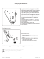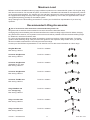
1
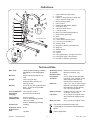
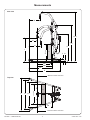
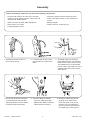
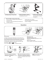
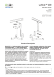
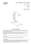
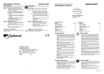
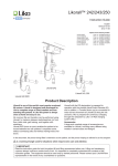
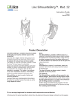
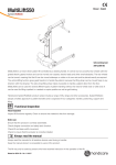
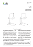
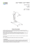
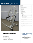
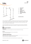
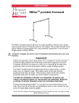
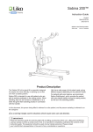
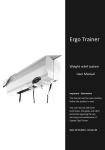
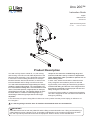
Uno 200™
Instruction Guide
English
7EN150105-05
2014-03-18
Applies to the following model:
Uno 200
Prod. No. 2010020
Product Description
Uno 200 is a fully electric mobile lift, i.e., both raising
and lowering of the lift arm and width adjustment of the
base are done electrically. Uno is designed to be used
in most of the common lifting situations, for example
transfers between bed and wheelchair, to and from the
toilet and bathtub and for lifting to and from the floor.
Uno 200 has three alternative height settings to always
enable the optimal lifting height. The intermediate position is the standard setting and is recommended in most
cases. The lowest position is appropriate, for example,
when lifting from the floor. The highest position is selected when there is a need for extra lifting height; e.g.,
when lifting to beds and gurneys that are not heightadjustable.
Unique for Uno 200 is the variable lifting range and
maximum load that is set by a number of adjustments.
These adjustments make it possible to optimize Uno for
different lifting needs.
In each case, assess the situation to determine how
many caregivers are needed to perform a safe and
ergonomically correct lifting and transferring operation.
Individual trial fitting and trial use of the sling and other
accessories is essential to ensure proper function and
safety during the use of the lift.
To ensure maximum safety for caregivers and patients,
Uno 200 is equipped for both mechanical and electrical
emergency lowering.
In this document, the person being lifted is referred to as the ”patient” and the person helping is referred to as
the ”caregiver”.
is a warning triangle used to warn of situations that demand extra care and attention.
IMPORTANT!
Read the instructions for both the patient lift and the lifting accessories before use. Lifting and transferring a
patient always involves a degree of risk. A complete understanding of the contents of instructions is essential, and only trained personnel should use the equipment. When in doubt, contact Liko/Hill-Rom.
Table of Contents
Safety Instructions........................................................2
Definitions.....................................................................3
Technical Data..............................................................3
Measurements.......................................................... 4-5
Assembly.................................................................. 6-7
Operation.................................................................. 7-8
Adjustments..................................................................9
Charging the Batteries................................................10
Maximum Load...........................................................11
Recommended Lifting Accessories.......................11-12
Simple Troubleshooting .............................................13
Care and Maintenance...............................................14
NOTE! This instruction guide contains information that is important for users of the product. A complete understanding of the contents of the instruction guide is essential, and only personnel who are well informed should use
the equipment. Remember to keep the instruction guide readily accessible for users of the product.
Safety Instructions
Before using the lift for the first time, make certain that:
• the lift is assembled according to the assembly instructions
• the lifting equipment is correctly applied to the lift
• the batteries have been charged for at least 12 hours
• you have read and understood the instruction guides for the lift and lifting accessories
• personnel using the lift have received appropriate instructions and training.
Before lifting always make certain that:
• you have selected the correct type, size, material, and design of slings and accessories to safely meet
the patient’s needs
• lifting accessories are not damaged
• the lifting accessory is correctly applied to the lifting equipment
• the lifting accessory is correctly and securely applied to the patient, so that no personal injury can occur
• the sling’s strap loops are correctly fastened to the sling bar hooks when the sling strap is extended, but
before the patient is lifted from the underlying surface
• the lift is set for the correct max. load.
Unbalanced lifting poses a tipping risk and may damage the lift equipment!
Never leave a patient unattended in a lifting situation!
Uno 200 is tested by an accredited testing institute and comply with the requirements of the directives for medicaltechnical Class 1 products (MDD 93/42/EEC).
Uno 200 complies with the requirements according to IEC 60601-1, IEC 60601-1-2, EN ISO 10535, UL-60601-1
and CAN/CSA C22.2 No. 601.1.
No modification of this product is allowed. Contact Liko/Hill-Rom for further information.
Particular care must be taken when using strong sources of electromagnetic interference, such as diathermy, etc,
so that cables are not positioned on or near the lift. If you have questions, please consult the responsible assistivedevice technician or the supplier.
This equipment is not suitable for use in the presence of flammable mixtures.
Maximum load: 160 kg (350 lbs) / 200 kg (440 lbs) depending on mounting alternative (see page 5).
Uno 200 • 7EN150105-05
2
w w w .l i ko. com
Definitions
1
2
1.
2.
3.
21
3
17
20
4
19
5
18
16
6
15
7
8
14
9
Forward direction
10
11
6
12
22
23
13
24
4.
5.
6.
7.
8.
9.
10.
11.
12.
13.
14.
15.
16.
17.
18.
19.
20.
21.
22.
23.
24.
Upper attachment (lift motor)
Lift mast
Holder for quick reference guide with
colour codes for sling sizes
Manoeuvering handle
H and control
Control unit with built-in battery
Emergency stop
Cable for hand control
Locking handle
Motor for base-width adjustment
Rear wheels with brake
Base
Front wheels
Lower attachment (lift motor)
Lift motor (incl. actuator)
Product decal
Emergency lowering (mechanical)
Sling bar
Safety latches
Flexlink
Lift arm
LED (yellow light) - charger connected
LED (green light) - lift activated
Emergency lowering (electrical)
Technical Data
Max. load:
160 kg (350 lbs) /200 kg (440 lbs)
depending on mounting alternative
Material:
Painted steel with lacquer top
coat.
Weight:
Total: 40 kg (88 lbs)
Heaviest dismountable part:
20.5 kg (45 lbs)
Wheels:
Front: 75 mm (2.9 in) twin wheels.
Rear: 75 mm (2.9 in) lockable
twin wheels.
Operating forces
of controls:
Buttons on hand control: 4 N
Buttons on display: 4 N
Electrical data:
24 V
Intermittent
operation:
Int. Op 10/90, active operation
max 2 min. Out of a time of 100,
active must be less than 10,
though not more than 2 min
Batteries:
2 pcs. 12 V, 2,9 Ah, valve-regulated lead-acid gel-type batteries.
New batteries are provided by
your Liko representative.
Turning diameter: 1330 mm (52.4 pulg.)
Battery charger:
Emergency
lowering:
Mechanical and electrical
External charger, 100-240 V AC,
50-60 Hz, max 500 mA.
Lift motor:
Lifting speed
(without load):
22 mm (0.9 in)/s
for max. load 160 kg (350 lbs)
18 mm (0.7 in)/s
for max. load 200 kg (440 lbs)
24 V, permanent magnet motor
with mechanical safety mechanism
Motor for base:
24 V, permanent magnet motor
Sound level:
42 dB(A)
The device is intended for indoor use.
Protection class:
IP X4
Expected life
time:
ype B degree of protection against electrical
T
shock.
10 years
Class II equipment.
Uno 200 • 7EN150105-05
3
w ww. liko. com
Measurements
Side view
M
Amax
N
Amin
O
E
600 mm
L
Ref. 1
F F1
B3
B2
B1
B
Maximum reach of lift arm
Top view
C
D
D1
700 mm
Ref. 2
D2
Maximum reach of lift arm
Uno 200 • 7EN150105-05
4
w w w .l i ko. com
Adjustments of maximum load/lifting height
X
Y
The lift motor can be mounted in four different
combinations:
X1: o
uter position (X) on the lift arm
upper position (1) on the lift mast
X2: outer position(X) on the lift arm
lower position (2) on the lift mast
Y1: inner position (Y) on the lift arm
upper position (1) on the lift mast
Y2: inner position (Y) on the lift arm
lower position (2) on the lift mast
1
2
The different mounting alternatives affect the lift's lifting
height and maximum allowable load. See "Table of
measurements" below.
Max. load in kg. Dimensions in mm.
A*
C
B
max
B1
D
L*
B2 B3**
min
D1
max
min
max
min
D2**
E*
F
F1
max min
Lifting range
Max. load
Mounting
alternative
Table of measurements
M
N
O
X1
1835 1430
620
200 1785 1380 1220 910 620 600
1735 1330
545
1110
675
1000
570
875
255
1080
1590 710
1030 105 20 1540 660
980
1490 610
885
370 295 425
X2
1755 1430
605
200 1705 1380 1220 910 620 545
1655 1330
545
1110
675
1000
570
875
255
1080
1495 630
1030 105 20 1445 580
980
1395 530
870
340 295 495
Y1
1940 1430
615
160 1890 1380 1220 910 620 595
1840 1330
540
1110
675
1000
570
875
255
1080
1705 675
1030 105 20 1655 625 1035 440 295 460
980
1605 575
Y2
1845 1430
605
160 1795 1380 1220 910 620 545
1745 1330
545
1110
675
1000
570
875
255
1080
1600 565
1030 105 20 1550 515 1040 370 295 570
980
1500 465
A*
C
B
max
min
X1
72.2
440 70.3
68.3
56.3
54.3
52.3
48
X2
69.1
440 67.1
65.2
56.3
54.3
52.3
Y1
76.4
352 74.4
72.4
Y2
76.4
352 74.4
72.4
B1
B2
D
L*
B3**
D1
D2**
E*
F
F1
max min
Lifting range
Max. load
Mounting
alternative
Max. load in lbs. Dimensions in inch.
M
N
O
max
min
max
min
24.4
35.8 24.4 23.6
21.4
43.7
26.5
39.3
22.4 34.4
10
42.5
40.5
38.5
62.6
4.1 0.8 60.6
58.6
48
23.8
35.8 24.4 21.4
21.4
43.7
26.5
39.3
22.4 34.4
10
42.5
40.5
38.5
58.8 24.8
4.1 0.8 56.8 22.8
54.8 20.8
56.3
54.3
52.3
48
24.2
35.8 24.4 23.4
21.3
43.7
26.5
39.3
22.4 34.4
10
42.5
40.5
38.5
67.1 26.6
4.1 0.8 65.1 24.6 40.5 17.3 11.6 18.1
63.1 22.6
56.3
54.3
52.3
48
23.8
35.8 24.4 21.4
21.4
43.7
26.5
39.3
22.4 34.4
10
42.5
40.5
38.5
4.1 0.8
63
61
59
28
26
24
34.6 14.5 11.6 16.7
34 13.4 11.6 19.4
22.3
20.3 40.7 14.5 11.6 22.4
18.3
* Measures vary depending on height setting level, see "Assembly" page 6. NOTE! The measures apply for a lift equipped with standard sling
bar and standard wheels. Before changing lifting equipment or wheels, ensure that the lift still achieves the desired lifting height.
** Reference measurements according to Standard EN ISO10535:2006.
Uno 200 • 7EN150105-05
5
w ww. liko. com
Assembly
Before assembling, make sure you have the following components:
• Lift mast with: lift arm, lift motor (incl. actuator),
holder for quick reference guide, control unit and
sling bar with safety latches
• Base with motor for base-width adjustment
• Hand control, incl. cable
• Locking handles (1 pair)
1. On delivery, the lift is set for a
max. load of 160 kg.
• Instruction guide and quick reference guide
•T
ools: 8 mm Allen wrench 17 mm closed-end
wrench
• Battery charger
• Cable cover incl. screws (2 pcs).
2. Lock
both rear wheels. Place
the lift mast in the tube on the
base.
3. The lifting height can be set at
three different levels. The distance
between two holes is 50 mm (2 in).
The middle hole is recommended
in most cases. See page 9 for more
detailed information on the adjustment options.
3 2 1
4. Secure the lift mast by using the
accompanying locking handles.
Adjust the position of the handles
so that they point downward.
Uno 200 • 7EN150105-05
5. C
onnect cables as follows:
- Lift motor cable to socket 1
- Base-motor cable to socket 2
- Hand control to socket 3.
6
6. Guide the cables through the
opening on the cable cover.
Press the cable cover up into
position. Use a screwdriver to
secure the cable cover with the
accompanying screws (2 pcs).
w w w .l i ko. com
XS
S
MS
M
L
XL
XX
L
7. Place the quick reference guide in
its intended holder on the lift mast.
8.Reset the emergency stop by
turning the button in the direction
indicated by the arrows.
After assembly, check to ensure that:
• lift arm motions correspond with the buttons on
the hand control
• emergency lowering (mechanical and electrical)
functions properly
9. Before using the lift for the
first time, charge the battery
for a minimum of 12 hours,
see page 10.
• wheel brakes work properly
• base-width adjustment works properly
•the lift is charging.
Operation
Hand control
Operate the lift using the pushbuttons on the handcontrol.
For raising and lowering, press either of the two upper pushbuttons. Directional arrows show the direction of movement
(up/down) when the hand control is held as illustrated.
For base-width adjustment, press either of the two lower
push-buttons:
wider,
narrower
The movement stops when you release the buttons.
Electrical emergency lowering
The lift arm is lowered electrically by
pressing the “
-button ".
Uno 200 • 7EN150105-05
Emergency stop
Activate emergency stop:
Push the red emergency stop button on the
control unit.
Reset emergency stop:
Turn the button in the direction of the arrows.
Mechanical emergency lowering
The lift arm is lowered mecanically by
turning the red emergency-lowering
cylinder in the direction of the arrows
(clockwise).
7
Never move the lift by
pulling the actuator!
w ww. liko. com
Locking
Unlocking
XS
S
MS
M
L
XL
XX L
XS
S
MS
M
L
Locking the wheels
The rear wheels can be locked for rotation and lateral movement. To lock the wheels press the brake pedal down with
your foot. Release the wheels by pressing the pedal up.
During lifting, wheels should remain unlocked so that the
lift may shift to the patient's center of gravity. The wheels
should however be locked if there is a risk for the lift moving
into the patient, for example when lifting from the floor.
XL
XX
L
Quick reference guide
A quick reference guide comes with the lift and
should be kept easily accessible in its holder on
the lift mast, so that users of the lift may easily
remind themselves about the use of the lift.
NOTE! The quick reference guide does
not replace the lift's instruction guide.
Locked wheels during lifting increases the risk of
the lift tilting over.
Bild 1.
Installation of Latches
After installation, ensure that the
spring loaded clip is taut against
the sling bar and moves freely in
the sling bar hook.
Position of the Lift when Lifting
From/To:
Bed
Bild 2.
Lift correctly!
Before each lift, make sure that:
– the Sling loops at opposite sides of the Sling are at the same height
– all the Sling loops are fastened securely in to the Sling bar hooks
– the Sling bar is level during the lift, see Figure 1.
If Sling bar is not level (see Figure 2), lower the user to a firm
surface and adjust according to the Sling in use Instruction
Guide.
An improper lift can be uncomfortable for the user and cause
damage to the lift equipment! (see Figure 2).
Chair/Hygiene chair
Floor
NOTE: Place a pillow under the patient’s head for
increased performance and comfort. Always have
the wheels locked when lifting from the floor.
Uno 200 • 7EN150105-05
8
w w w .l i ko. com
Adjustments
Adjustment of maximum load
For guidance on adjustment alternatives, see "Adjustments of maximum load / lifting height", page 5.
Y
Y X
Max 160 kg
Max 160 kg
X
Max 200 kg
Max 200 kg
1. Use Allen wrench 8 mm and closed-end wrench 17 mm
to dismount the upper lift motor attachment from lift arm.
For maximum load 160 kg/350 lbs choose position (Y)
on the lift arm.
For maximum load 200 kg/440 lbs choose position (X)
on the lift arm.
Note! Study the markings on the lift.
On delivery, the lift is set for a max. load of 160 kg/350 lbs),
in position (Y).
2. Secure the upper lift motor attachment in desired
position using accompanying bolt and locking nut.
Use Allen wrench 8 mm and closed-end wrench
17 mm.
Adjustment of lifting height
A
B
1
2
Via the lower lift motor attachment
A. Use Allen wrench 8 mm and closed-end wrench
17 mm to dismount the lower lift motor attachment
from the lift arm. Choose the upper hole (1) for a
higher lifting height and the lower hole (2) for a
lower lifting height.
B. Secure the lower lift motor attachment in desired
position using accompanying bolt and locking nut.
Use Allen wrench 8 mm and closed-end wrench
17 mm.
On delivery, the lower lift motor attachment is
mounted in the lower hole (2).
Via the lift mast Release the lift mast by loosening the locking handles.
The lifting height can be adjusted in three different
levels on the lift mast. Choose one of the three holes
according to the illustration above. The middle hole is
recommended in most cases.The lower hole is recommended when extra lifting height is needed. The upper
hole is recommended when a lower lifting height is
needed. Secure the lift mast by using the accompanying locking handles. Adjust the position of the handles
so that they point downward.
The distance between two holes is 50 mm.
See " Table of measurements", page 5.
If this adjustment not is sufficient, see "Adjustment
of lifting height - Via the lower lift motor attachment",
page. 9.
Uno 200 • 7EN150105-05
9
w ww. liko. com
Charging the Batteries
For maximum battery life, batteries must be charged
regularly. We recommend charging after use or each
night. If the lift is not in daily use, we recommend that
the emergency stop be pressed in after the lift has been
used. This breaks the current and conserves battery
power. Make sure the lift is fully charged before pressing in the emergency stop.
On the control unit there is a display with a yellow LED
(A) that illuminates while the charger is connected to
an electric socket. Maximum charge is reached after
about 12 hours. When the batteries are fully charged,
the charger switches automatically to maintenance
charging.
When battery capacity is low (approx. 2-10 lift cycles
remain) an audible signal sounds. In this case, charge
the lift immedately.
Never charge batteries in a wet area!
The lift cannot be charged with the emergency stop
button activated.
A
Charging procedure
1
With external charger:
1. Connect the charger cable to the charger socket
under the control unit.
2. Connect the charger to a 100-240 V AC electric
socket.
3. When the charger is connected a LED indicates:
-yellow light indicates charging
-green light indicates maintenance charging.
2
3
Note! The lift does not operate when the charger cable is plugged into an electric socket.
Old batteries are to be left at the nearest recycling station
or given to personnel authorized by Liko/Hill-Rom.
Uno 200 • 7EN150105-05
10
w w w .l i ko. com
Maximum Load
Different maximum allowable loads may apply to different products on the assembled lift system: lift, sling bar, sling
and other accessories. For the total lift system, the lowest max. allowable load indicated for the respective products
on the system always applies. For example: An Uno 200 that is approved for 160 kg (350 lbs)/200 kg (440 lbs) may
be equipped with a lifting accessory that is approved for 300 kg (660 lbs). In this case, the applicable max. load is
160 kg(350 lbs)/200 kg (440 lbs) for the total lift system.
Study markings on the lift and lifting accessories or contact your Liko/Hill-Rom representative if you have any
questions.
Recommended Lifting Accessories
Use of accessories other than those recommended may entail risk.
Sling bars and accessories recommended for use with Uno 200 are described below.
Changing sling bars and adding extra accessories affects the maximum lifting height of the lift. Before changing
sling bars and accessories, it is important to ensure that it will still be possible to achieve the desired lifting height
for situations in which the lift will be used.
For choice of appropriate slings and other accessories, consult our brochure “Lifting Accessories”. For further
guidance when selecting slings, study the instruction guides for the respective sling models. Here, you will find
advice on suitable combinations of Liko sling bars and Liko slings.
Contact your Liko/Hill-Rom representative or visit www.liko.com for advice and information on Liko’s range.
SlingBar Mini 220
Max 205 kg / 450 lbs.
Prod. No. 3156005
Universal SlingBar 350
Max 300 kg / 660 lbs.
Prod. No. 3156074
Universal SlingBar 450
(Standard for Uno 200)
Max 300 kg / 660 lbs.
Prod. No. 3156075
Universal SlingBar 600
Max 300 kg / 660 lbs.
Prod. No. 3156076
Universal TwinBar 670
Max 300 kg / 660 lbs.
Prod. No. 3156077
Sling SideBars 450
incl. storage bag
Max 300 kg / 660 lbs.
Prod. No. 3156079
Sling Cross-bar 450
Max 300 kg / 660 lbs.
Prod. No. 3156021
Sling Cross-bar 670
Max 300 kg / 660 lbs.
Prod. No. 3156018
Uno 200 • 7EN150105-05
11
w ww. liko. com
SlingBar Cover Paddy 30
(fits Universal SlingBar 350, 450 and 600
and SlingBar Slim 350)
Bag for SlingBars
Prod. No. 3607001
Prod. No. 2001025
Quick-release Hook
Liko’s Quick-release Hook system enables quick and easy
exchange of lifting accessories on Liko’s mobile and stationary
lifts. Uno 200 requires Q-link 13 for use with Quick-release
Hook.
Quick-release Hook Universal fits Universal SlingBar 350,
450 and 600 (Prod. No. 3156074-3156076). Quick-release
Hook TDM fits SlingBar Mini 220 (Prod. No. 3156005), Sling
Cross-bar 450 and 670 (Prod. No. 3156021 and 3156018) and
Universal TwinBar 670 (Prod. No. 3156077).
When a sling bar mounted with the Quick-release Hook system
is used, the lifting height will be 33 mm shorter than with a
permanently mounted sling bar.
See ”Guide to Liko´s Quick-release Hook System”, which can
be downloaded from our website, www.liko.com, or contact
Liko/Hill-Rom for more information on the advantages and use
of the Quick-release Hook system.
Scale
In need of weighing persons in combination with Uno 200 we
recommend LikoScale 350 (Adapter 12 mm is required).
Max. load 350 kg (770 lbs).
LikoScale 350 is certified according to the european directive
NAWI 90/384 (Non Automatic Weighing Instruments).
Contact Liko/Hill-Rom for more information.
Uno 200 • 7EN150105-05
12
Quick-release Hook
Universal
Prod. No. 3156508
Quick-release Hook
TDM
Prod. No. 3156502
Y
X
Z
Q-link 13
Prod. No. 3156509
0
LikoScale 350
Adapter 12 mm
Prod. No. 3156228
Prod. No 2016504
w w w .l i ko. com
Simple Troubleshooting
The lift does not work up/down.
Width adjustment does not work
in/out.
1. Check that the emergency stop button is
not pushed in (p. 7).
2. Check that the cables to the control unit
are correctly connected (p. 6).
3. Check that the charger cable is not
connected to an electric socket.
4. Check that the battery is charged (p. 10).
5. If the lift still does not work satisfactorily,
contact Liko-Hill-Rom.
Battery charging does not work.
1. Check that the emergency stop button is
not pushed in (p. 7).
2. Check to ensure that the electric socket
is power-supplied.
3. Check that the charger cable is correctly
connected (p.10).
4. If the lift still does not work satisfactorily,
contact Liko/Hill-Rom.
The lift stops in the elevated position.
1. Check that the emergency stop button is
not pushed in (p. 7).
2. Use the electrical emergency lowering
to lower the patient to a stable underlying
surface (p 8).
3. Use the mechanical emergency
lowering to lower the patient to a stable
underlying surface (page 8).
4. Check that the battery is charged (p.10).
5. If the lift still does not work satisfactorily,
contact Liko/Hill-Rom.
If you hear unusual sounds.
Contact Liko/Hill-Rom.
Uno 200 • 7EN150105-05
13
w ww. liko. com
Care and Maintenance
Care and inspection
To ensure trouble-free operation, certain components should be checked each day the lift is used:
• Inspect the lift and check for any signs of external damage.
• Check the fixture of the sling bar.
• Check safety latch function.
• Check raising, lowering and base-width adjustment.
• Check the emergency lowering function (both electrical and mechanical).
• Charge the batteries each day the lift is used and check charger function.
When necessary, clean the lift with a moist cloth and check that the wheels are free from dirt. Find more
detailed information regarding cleaning and disinfection of your Liko/Hill-Rom product in the document
Care and Maintenance at our website: www.liko.com.
The lift should not be exposed to running water.
Service
Uno 200 must be inspected at least once per year, with particular attention to parts that are subject to wear.
Repairs and maintenance may only be carried out in accordance with Liko/Hill-Rom service manuals, by
authorized Liko/Hill-Rom service personnel and using original Liko/Hill-Rom spare parts.
Transportation and storage
During transportation, or when the patient lift is not to be used for some time, the emergency stop button should be
pushed in. The environment where the patient lift is transported and stored should have a temperature between
10 ˚C and 40 ˚C and a humidity between 30 % and 75 %. The air pressure should be between 700 and 1060 hPa.
Recycling
For instructions on how your Liko/Hill-Rom product should be recycled, please visit our website: www.liko.com.
Product changes
Liko’s products undergo continuous development, which is why we reserve the right to make product changes
without prior notice. Contact your Liko/Hill-Rom representative for advice and information about product upgrades.
Design and Quality by Liko in Sweden
Hill-Rom´s Management system are certified in accordance with ISO 9001 and its equivalent for the medical device
industry, ISO 13485. Hill-Rom´s Management system is also certified in accordance with environmental standard
ISO 14001.
w w w . l i k o . com
Manufacturer:
Liko AB
Nedre vägen 100
SE-975 92 Luleå
Sweden
[email protected]
© Copyright Liko AB 2014-03
Service agreements
Liko/Hill-Rom invites you to sign a service agreement for regular maintenance and inspection of your Liko/Hill-Rom
product.