1
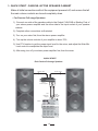
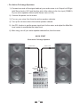
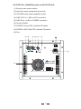
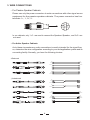
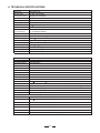
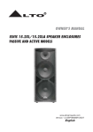
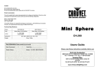
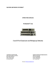
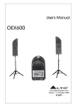
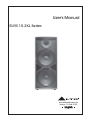
User's Manual
ELVIS 15.2XL Series
R
LTO
www.altoproaudio.com
Version 1.0 Feb. 2007
English
Unplug the product before electrical storms
occur and when unused for long periods of
time to reduce the risk of electric shock or
fire.
SAFETY RELATED SYMBOLS
CAUTION
RISK OF ELECTRIC SHOCK
DO NOT OPEN
External Connection
This symbol, wherever used, alerts
you to the presence of un-insulated
and dangerous voltages within the
product enclosure. These are voltages
that may be sufficient to constitute the
risk of electric shock or death.
Always use proper ready-made insulated
mains cabling (power cord). Failure to do
so could result in shock/death or fire. If
in doubt, seek advice, from a registered
electrician.
Do not Remove any Covers
This symbol, wherever used, alerts
you to important operating and maintenance instructions. Please read.
Protective Ground Terminal
AC mains (Alternating Current)
Hazardous Live Terminal
Within the product are areas where high
voltages may present. To reduce the risk
of electric shock do not remove any
covers unless the AC mains power cord
is removed.
Covers should be removed by qualified
service personnel only.
No user serviceable parts inside.
ON: Denotes the product is turned on.
OFF: Denotes the product is turned off.
WARNING
Describes precautions that should be
observed to prevent the possibility of
death or injury to the user.
Fuse
To prevent fire and damage to the
product, use only the recommended
fuse type as indicated in this manual.
Do not short-circuit the fuse holder.
Before replacing the fuse, make sure
that the product is OFF and disconnected
from the AC outlet.
CAUTION
Describes precautions that should be
observed to prevent damage to the
product.
Protective Ground
Disposing of this product should
not be placed in municipal waste
and should be separate collection.
Before turning the product ON, make sure
that it is connected to Ground. This is to
prevent the risk of electric shock.
Never cut internal or external Ground wires.
Likewise, never remove Ground wiring
from the Protective Ground Terminal.
WARNING
Power Supply
Ensure that the mains source voltage (AC
outlet) matches the voltage rating of the
product. Failure to do so could result in
damage to the product and possibly the user.
Operating Conditions
Always install in accordance with the
manufacturer's instructions.
1
To avoid the risk of electric shock and
damage, do not subject this product to
any liquid/rain or moisture. Do not use this
product when in close proximity to water.
Servicing
Refer all servicing to qualified service
personnel only.
Do not perform any servicing other than
those instructions contained within the
User's Manual.
Do not install this product near any direct
heat source.
Do not block areas of ventilation. Failure
to do so could result in fire.
Keep product away from naked flames.
IMPORTANT SAFETY INSTRUCTIONS
Read these instructions
Follow all instructions
Keep these instructions. Do not discard.
Heed all warnings.
Only use attachments/accessories
specified by the manufacturer.
Power Cord and Plug
Do not tamper with the power cord or plug.
These are designed for your safety.
Do not remove Ground connections!
If the plug does not fit your AC outlet seek
advice from a qualified electrician.
Protect the power cord and plug from any
physical stress to avoid risk of electric shock.
Do not place heavy objects on the power
cord. This could cause electric shock or fire.
Cleaning
When required, either blow off dust from
the product or use a dry cloth.
Do not use any solvents such as Benzol
or Alcohol.
For safety, keep product clean and free
from dust.
2
TABLE OF CONTENT
1. QUICK START - PASSIVE/ACTIVE SPEAKER CABINET........................4
-. For Passive Full-range Speakers
-. For Active Full-range Speakers
2. CONNECTION PLATE..............................................................................6
-. PASSIVE FULL-RANGE Speaker for ELVIS 15.2XL
-. Active FULL-RANGE Speaker for ELVIS15.2XLA
3. WIRE CONNECTIONS...............................................................................8
-. For Passive Full-range Speakers
-. For Active Full-range Speakers
4. TECHNICAL SPECIFICATIONS..................................................................9
3
1. QUICK START - PASSIVE /ACTIVE SPEAKER CABINET
Make all initial connections with all the equipment powered off, and ensure that all
the main volume controls are turned completely down.
-. For Passive Full-range Speakers
1). Connect one side of the speaker cable to the Output CHA/CHB or Binding Post of
your stereo power amplifier and the other side to the Input socket of your speaker
cabinet.
2). Complete other connections as illustrated.
3). Turn on your mixer first, then the stereo power amplifier.
4). Turn up the volume controls of your amplifier to about 70%.
5). Use PFL function to get the proper input level for the mixer, and adjust the Main Mix
Level control to manipulate the output level.
6). After using, turn off your stereo power amplifier first, then the mixer.
QUICK START
Elvis Passive Full-range Speakers
speaker cable
speaker cable
Stereo
Power Amplifier
Left
Main Mix
Output
Right
Main Mix
Output
Mixer
4
-. For Active Full-range Speakers
1). Connect one side of the signal cable at your audio mixer in to Output Left /Right
(with Stereo-Jack or XLR) and the other side of the cable in to the Line Input (COMBO)
of your active speaker cabinet (with Stereo-Jack or XLR).
2). Connect the power cord to mains.
3). Turn on your mixer first, then the active speaker cabinets.
4). Turn up the volume control of the active speaker cabinets.
5). Use PFL function to get the proper input level for the mixer, and adjust the Main Mix
Level control to manipulate the output level.
6). After using, turn off your active speaker cabinets first, then the mixer.
QUICK START
Elvis Active Full-range Speakers
speaker cable
speaker cable
Left
Main Mix
Output
Right
Main Mix
Output
Mixer
5
2. CONNECTION PLATE
- PASSIVE FULL-RANGE Speaker for ELVIS 15.2XL
(1) INPUT: Receive the power coming from an external power amplifier (SPK +1/-1
connected; +2/-2 not connected).
(2) THRU: Direct LINK for connect in parallel a second speaker cabinet (SPK +1/-1
connected; +2/-2 not connected).
LTO
R
ELVIS 15.2XL
SOUND REINFORCEMENT SPEAKER SYSTEM
POWER HANDLING:
CONTINUE - 500 Watts
PEAK - 1K Watts
IMPEDANCE:
4 ohms nominal
MODEL
SERIAL
DESIGNED AND DEVELOPMENT IN ITALY
INPUT
THRU
LINK
6
-. ACTIVE FULL- RANGE Speaker for ELVIS15.2XLA
(1) Bi-polar main power switch
(2) Input AC power socket with main fuse
(3) VOLUME main power amplifier control
(4) LINE OUT at + 4dB on XLR connector
(5) LINE IN at + 4dB on COMBO connector
(6) Ground Swicth
(7) POWER, Green LED, indicate ON status
(8) SIGNAL LIMIT, Red LED, indicate ON status
(9) Fan
(7) (5)
(4) (8) (3)
(6)
(1)
ON
VOLUME
OFF
0dB
NEW
TIDE
POWER
2
1
3
MIN
INPUT
LINK
MAX
SIGNAL
LIMIT
(2)
AC INPUT
BAL
POWER
Use only with a 250V fuse
100-120V~60Hz
FUSE: T6.3AL 250V
R
LTO
(9)
ELVIS 15.2XLA
MODEL
SERIAL
"WARNING" TO REDUCE THE RISK OF FIRE OR ELECTRIC SHOCK DO NOT EXPOSE THIS RODUCT TO RAIN OR MOISTURE.
7
3. WIRE CONNECTIONS
-. For Passive Speaker Cabinets
Please use only the power connectors to make connections with other signal source
equipment for the passive speaker cabinets. The power connector has four
terminals: 1+, 1-, 2+, 2-.
2-
1-
1+
2+
In our cabinets, only 1+/1- are used to connect the Speaker+/Speaker-, and 2+/2- are
not used.
-. For Active Speaker Cabinets
As to these circumstances, audio connections is mostly intended for the signal flow,
so, determine the wire configuration according to your real application system and its
connecting facility. Normally, you have the following choices:
Balanced
TIP RING SLEEVE
SLEEVE RING TIP
Tip
Ring
Sleeve
3
3
1
1
2
2
1
3
2
TIP RING SLEEVE
Tip
Ring
Sleeve
1
2
1
2
3
3
Tip
Ring
1
2
3
Sleeve
Unbalanced
1
Tip
Ring
3
2
Sleeve
TIP RING SLEEVE
Tip
1
3
2
Sleeve
1
2
3
1
2
3
TIP SLEEVE
Tip
TIP SLEEVE
SLEEVE TIP
Sleeve
Tip
Ring
TIP RING SLEEVE
SLEEVE RING TIP
1
2
3
3
1
1
2
2
Sleeve
3
8
Tip
Sleeve
Tip
Ring
Sleeve
1
2
3
4. TECHNICAL SPECIFICATIONS
Model No.
System Type
Continuous Power
Peak Power Rating
Sensitivity (1W, 1m)
Frequency Response
Impedance
Crossover Frequency
Protection
Low-Frequency
ELVIS15.2XL
3-Way Vented Box
500W AES Standard
1000W Peak
101dB /122 dB Max
55Hz /20kHz +/-6dB
4
Nominal
2200Hz 12dB/oct
Electronics High Frequencies Protection
2*15"/385mm Woofer
1"Compression Driver
Custom Horn with Polypropilene Reinforced
80 H 80 V
High-Frequency
Spherical Wave Guide
Horn Coverage
Connectors (+1/-1) 2 x SPK4 Input/Link @+1/-1 Connected - +2/-2 not connected
Enclosure
Trapezoidal Cabinet in 18mm Particle Board P.B. -Covered with Resistant Carpet -Black Metal Grille Protection
Dimensions (H x W x D) 1114 452 449 mm
Net Weight (lbs/kg) 93.92lbs/42.60kg
Gross Weight (lbs/kg) 107.94lbs/48.96kg
Volume
11.91CFT
Model No.
Active System Type
Low Output Power
High Output Power
Max SPL 1mt
ELVIS15.2XLA
2-Way Bi-Amp
350 Watt EIAJ
65 Watt EIAJ
122dB SPL Calculated
Frequency Response 55Hz-20kHz at -10dB
Protection Low - High Analog Limiter
Low Frequency Device 2 x 15" woofer / 2.5" Voice Coil
High Frequency Device 1" Driver / 1" Voice Coil
Coverage (H x V )
80 H x 80 V Spherical Wave Guide
Line +4dB
Input Sensitivity
Input Impedance
Connectors
Enclosure
External Control
Net Weight (lbs/kg)
30k Balanced / 15k Unbalanced
Input with Combo / Link with XLR
Trapezoidal Shape / Particle Board/ Plastic Handle / Gray Carpet Finishing
Line Volume / Clipping LED indicator / Ground Switch
1114 x 452 x 449 (mm)
97.89lbs/44.4kg
Dimensions (H x W x D)
Power Section
Output Power
350 WATT EIAJ (300WATT RMS)
Impedance
4
S/N ratio
>110 dB/A
Load
Distortion
<0.05% (THD, DIM, SMPTE)
Gain
32dB
Bandwidth
10Hz to 50 kHz
Protections
Overload / Short Circuite / Soft Clip Limiter / Thermal Protection Fan Cooling
9
SEIKAKU TECHNICAL GROUP LIMITED
No. 1, Lane 17, Sec. 2, Han Shi West Road, Taichung 40151, Taiwan
http://www.altoproaudio.com Tel: 886-4-22313737
email: [email protected] Fax: 886-4-22346757
All rights reserved to ALTO. All features and content might be changed
without prior notice. Any photocopy, translation, or reproduction of part of this
manual without written permission is forbidden. Copyright c 2007 SEIKAKU GROUP
NF02169-1.1