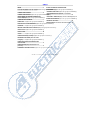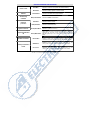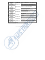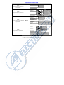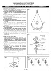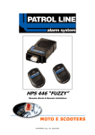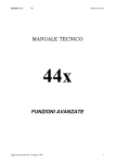
1
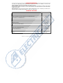
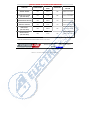
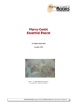
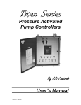
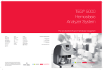
HPS 685
HPS 685/55
HPS 685/55 E
HPS 685 E
12 VOLT
Thanks for choosing one
of our products.
Please, read this manual carefully and
keep it for any further reference.
Suitable for all the vehicles endowed
with original remote control
to close and open the CDL.
HPS 685 rev. 00 February 2006 pag. 1 di 15 COD: 00-99-0068510
INDICE
INDEX ................................................................... 2
ACOUSTIC SIGNALS IN ARMING AND
DISARMING ... Σφάλµα! ∆εν έχει οριστεί σελιδοδείκτης.
ELECTRIC WIRINGS FOR THE ALARMΣφάλµα! ∆εν έχει οριστεί σελιδοδείκτης.
”SUMMER” FUNCTIONΣφάλµα! ∆εν έχει οριστεί σελιδοδείκτης.
CONNECTION DIAGRAM ....................................... 4
”ANTIAGGRESSION FUNCTION” (only version
CONNECTION EXAMPLEΣφάλµα! ∆εν έχει οριστεί σελιδοδείκτης.
“685 E”) .............................................................. 12
ADJUSTEMENT ULTRASONIC SENSOR (only
version 685/55)Σφάλµα! ∆εν έχει οριστεί σελιδοδείκτης.
COMMAND PROGRAMMING ................................. 7
FINAL TEST .... Σφάλµα! ∆εν έχει οριστεί σελιδοδείκτης.
”ANTITHEFT” FUNCTION (only version “685 E”)Σφάλµα! ∆εν έχει οριστεί σελιδοδείκτης.
ALARM MAINTENANCEΣφάλµα! ∆εν έχει οριστεί σελιδοδείκτης.
TECHNICAL FEATURES ....................................... 14
QUICK GUIDE TO ACTIVATE THE FUNCTIONS ... 15
SOLUTION TO LITTLE PROBLEMSΣφάλµα! ∆εν έχει οριστεί σελιδοδείκτης.
WORKING ...... Σφάλµα! ∆εν έχει οριστεί σελιδοδείκτης.
NEUTRAL TIME AND CHECK CONTROLΣφάλµα! ∆εν έχει οριστεί σελιδοδείκτης.
ALERT STATE . Σφάλµα! ∆εν έχει οριστεί σελιδοδείκτης.
PANIC ALARM ..................................................... 10
ALARM ........... Σφάλµα! ∆εν έχει οριστεί σελιδοδείκτης.
SIREN EXCLUSION (if linked)Σφάλµα! ∆εν έχει οριστεί σελιδοδείκτης.
MEMORIA DI ALLARME (solo con sirena
collegata) ....... Σφάλµα! ∆εν έχει οριστεί σελιδοδείκτης.
SIREN LIMITATION FOR CONSECUTIVE
ACTIVATIONS ..................................................... 11
POWER BACKUP(only with the siren self
powered) ............................................................ 11
EMERGENCY MECHANICAL KEYΣφάλµα! ∆εν έχει οριστεί σελιδοδείκτης.
HPS 685 rev. 00 February 2006 pag. 2 di 15 COD: 00-99-0068510
ELECTRIC WIRINGS FOR THE ALARM
Red Wire:
Connect to a fused 12 volt positive line from the battery.
Power 12 Volt
Black Wire:
Blinkers
Yellow Wires:
Alarm arming
command
White/Yellow Wire:
Blue Wire:
Connect to battery negative or vehicle chassis.
Connect to the flasher wires (right and left).
Connect to a wire of the blinkers.
Connect to the door switch.
Perimeter
protection
Blue/Red Wire:
Connect to the bonnet switch.
Ignition switch on
Green/Black Wire:
Connect to a positive under key.
Engine Immobilization
8A
Green/White Wire:
These wires are from a potential free relay with a maximum
current of 8A. This relay is open when the alarm is triggered
and the ignition key is on. It may be used to control the fuel
pump.
Modules Command
Brown Wire:
Negative output with the alarm armed. Connect to the
command wire for the optional modules. Max. current 100 mA.
White Wire:
Positive auxiliary control to avoid the disarming. For the
wiring, make reference to the technical sheet of the vehicle.
Green Wire:
Negative auxiliary control to avoid the disarming. For the
wiring, make reference to the technical sheet of the vehicle.
Auxiliary commands to
unlock
HPS 685 rev. 00 February 2006 pag. 3 di 15 COD: 00-99-0068510
Programming
button
Grey/Black Wire:
Connect to the GREY/BLACK wire of the programming push
button.
LED command
White/Black Wire:
Connect to the black wire of the signalling LED. Max 100mA.
Plant
predisposition
4 pins connector:
Connection for the ultrasonic module HPS 55.
Extra siren
command
White/Red Wire:
Negative command of device in alarm. Max 1Amp.
Windows rising
“COMFORT” type
command
Brown/Black Wire:
30 seconds negative command useful for the windows rising (if
endowed with comfort system). Max 1A.
Opening
switch control
Violet Wire:
Switch control for door opening command through key. To be
used only when the original blinkers flashing is missing.
Closing
switch control
Yellow/Blue Wire:
Switch control for door closing command through key. To be
used only when the original blinkers flashing is missing.
Opening
engine control
Black/Pink Wire:
Engine control for opening command trough remote control. To
be used only when the original blinkers flashing is missing.
Closing
engine control
Black/Blue Wire:
Engine control for closing command trough remote control. To
be used only when the original blinkers flashing is missing.
For the wires connection, take a look to the technical sheet of the vehicle.
HPS 685 rev. 00 February 2006 pag. 4 di 15 COD: 00-99-0068510
WIRING DIAGRAM CONNECTION
HPS 55
Connect the ultrasonic capsules
following the right connector colors
HPS 685
20 19 18 17 16 15 14 13 12 11
10
9
8
7
6
5
4
3
2
OFF
1
ON
HPS 55
ULTRASONIC SENSOR
Connect the emergency
wired key
+ 30
RED Pos. 11
+ 30
POSITIVE FIXED
WHITE/BLACK Pos. 4
BLACK
RED
GREEN/BLACK Pos. 14
ENGINE BLOCK MAX 8A
PROGRAMMING BUTTON
GREEN/WHITE Pos. 12
GREEN/WHITE Pos. 13
BLACK Pos. 15
GREY/BLACK Pos .18
YELLOW Pos. 9
YELLOW Pos. 10
+ 15
POSITIVE UNDER KEY
NEGATIVE FIXED
INDICATOR LIGHTS
Pos .3
BLUE
DOORS BUTTON
WHITE/YELLOW Pos. 17
BLUE/RED
BONNET BUTTON
POSITIVE COMMAND OF
ARMING AND DISARMING
DIODE
already present
OPTIONAL BUTTON
(ex. trunk)
CONNECTION FOR THE VEHICLE WITHOUT
THE ORIGINAL FLASH LAMPS
WHITE Pos. 16
AUXILIAR POSITIVE CHECK
FOR ARMING BLOCK
GREEN Pos. 20
AUXILIAR NEGATIVE CHECK
FOR ARMING BLOCK
WHITE/RED Pos. 1
SIREN COMMAND
Max 1Amp
PURPLE Pos . 6
Lock and unlock check
trough the external lock
YELLOW/BLUE Pos . 7
USE THEM ONNLY IF THERE ISN'T
THE ORIGINAL BLINKER FLASHING
BROWN Pos. 5
BLACK/PINK Pos . 8
ADDITIONAL MODULES
COMMAND Max 100mA
BLACK/BLUE Pos . 19
MARRONE/NERO Pos. 2
TEMPORIZED NEGATIVE COMMAND
30 SECONDS WINDOWS SLOPE
COMFORT SYSTEM. Max 1A
Rev.00 di May/2006
HPS 685 rev. 00 February 2006 pag. 5 di 15 COD: 00-99-0068510
EXAMPLES OF CONNECTIONS
YELLOW alarm
to the left blinker
Type 1:
connections with a car equipped whit
original flashing.
HPS 685
YELLOW alarm
to the right blinker
WHITE/YELLOW alarm
1N4004 Diode
to the front left blinker
YELLOW alarm
to the lateral left blinker
Type 2:
to the rear left blinker
connections with a car equipped whit
original flashing in separated lines
HPS 685
to the front right blinker
YELLOW alarm
to the lateral right blinker
to the rear right blinker
WHITE/YELLOW alarm
YELLOW alarm
YELLOW alarm
to the left blinker
to the blinker right
WHITE/YELLOW alarm
Type 3:
connections with a car not equipped whit
original flashing.
HPS 685
BLACK/BLUE alarm
BLACK/PINK alarm
YELLOW/BLUE alarm
VIOLET alarm
to the POSITIVE command wire of the CDL closing
to the POSITIVE command wire of the CDL opening
to the NEGATIVE command wire of the CDL switch closing
to the NEGATIVE command wire of the CDL switch opening
1N4004 diode
to the front left blinker
YELLOW alarm
to the lateral left blinker
to the rear left blinker
to the front blinker right
YELLOW alarm
Type 4:
connections with a car not equipped whit
original flashing in separated lines
HPS 685
to the lateral blinker right
to the rear blinker right
WHITE/YELLOW alarm
BLACK/BLUE alarm
BLACK/PINK alarm
YELLOW/BLUE alarm
VIOLET alarm
to the POSITIVE command wire of the CDL closing
to the POSITIVE command wire of the CDL opening
to the NEGATIVE command wire of the CDL switch closing
to the NEGATIVE command wire of the CDL switch opening
HPS 685 rev. 00 February 2006 pag. 6 di 15 COD: 00-99-0068510
ULTRASONIC SENSOR ADJUSTMENT (version 685/55 only)
ADJUSTMENT OF THE ULTRASONIC SENSOR SENSITIVITY:
Ultra-sounds adjustment
The sensitivity of the ultrasonic sensor can be modified working on the regulation
trimmer of the module. Turn the trimmer clockwise to increase the sensitività and
anticlockwise to decrease it. Be careful: a non correct adjustment can cause false
alrms.
Module HPS 55
COMMANDS PROGRAMMING
Once the electric connections are over, it is necessary to syncronize the original remote control of the vehicle with
the alarm following this procedure:
PROCEDURE OF FIRST PROGRAMMATION
1. Take off the ignition key and turn clockwise (ON) the mechanical key of the alarm.
The LED of the dashboard ON fixed and 10 quick flashings will confirm that the syncronization is started.
2. Verify that the car is completely closed (bonnet, doors and boot) and press the closing button of the original
remote control.
3. Once the flashings are over, the switching off of the LED and an acoustic signal will confirm that the closing
command has been memorized.
4. Press the opening button of the original remote control.
5. Once the flashings are over, an acoustic signal will confirm that the opening command has been memorized
and the procedure is finished.
HPS 685 rev. 00 February 2006 pag. 7 di 15 COD: 00-99-0068510
PROCEDURE OF PROGRAMMATION AFTER THE FIRST ONE.
In case it would be necessary to erase the previous programmation, it must be followed the procedure here under to
repeat the syncronization:
1.
Turn anticlockwise (OFF) the mechanical key of the alarm.
2.
Switch on, and leave on, the ignition key.
3.
Turn clockwise (ON) the mechanical key of the alarm.
The LED of the dashboard ON fixed and 10 quick flashings will confirm that the syncronization is started.
4.
Switch off the ignition key, verify that the car is completely closed (doors, bonnet and boot) and press the
closing button of the original remote control.
5.
Once the flashings are over, the switching off of the LED and an acoustic signal will confirm that the
closing command has been memorized.
6.
Press the opening button of the original remote control.
7.
Once the flashings are over, an acoustic signal will confirm that the opening command has been
memorized and the procedure is finished.
Optional Functions Available
In case the original remote control has more buttons and, pressing for a second time the closing button, the blinkers
flash like the first closing, it is possible to syncronize the following extra functions:
•
Panic Alarm
•
Siren Exclusion
To enable them
When switching on through the mechanical key, during the 10 quick flashings of the blinkers (beginning of the
commands programming phase) press for 3 seconds the programming button of the alarm.
To disable them
Ripeat the phase of programming without pressing the programming button.
FINAL TESTING
Once the programmations are over and once verified that the car is completely closed, press the closing button of
the original remote control and verify that the LED on the dashboard is ON.
Test all the functions and verify the regulation of the crash and ultrasonic sensors.
Press the opening button of the original remote control and verify that the LED of the dashboard switches off.
HPS 685 rev. 00 February 2006 pag. 8 di 15 COD: 00-99-0068510
SOLUTION TO LITTLE PROBLEMS
Here under, a simple and useful guide to solve little problems:
•
Check the power supply of the alarm.
THE ALARM
•
Verify that the mechanical key of the alarm is clockwise turned (position "ON”).
DOES NOT ARM
•
Check that on the Green/Black wire there is not a positive with the ignition key “off”.
•
If the problem is not solved, repeat the syncronization of the original remote control.
•
Repeat the syncronization procedure of the original remote control.
•
Programm the “acousting signalling of arming and disarming” function through the
programming button.
•
Verify that all the doors are well closed.
•
Verify the regulation of the crash sensor
AFTER ARMING
•
If the problem is not solved, disconnect the sensors (one by one) and identify the defective
one.
THE VEHICLE DOES NOT
•
Verify that the alarm is disarmed (LED off).
SWITCH ON
•
Verify the connection of the wire GREEN/WHITE of the alarm. We suggest a soft soldering.
•
Verify if the car is endowed with “self closing” function (original function which close
authomatically the cdl if is not opened a door).
THE ALARM ARM WHEN
OPENING THE CAR
THE ALARM DOES NOT EMIT
ANY SOUND WHEN ARMING
"BEEP" SIGNALLING
THE ALARM ARMS
BY ITSELF
HPS 685 rev. 00 February 2006 pag. 9 di 15 COD: 00-99-0068510
User’s Manual
Thaks for choosing one of our products.
Please, read this manual carefully and keep it for any further reference.
WORKING
ALARM ARMING
Press the CLOSING button of the remote control. The arming will be confermed by:
•
3 acoustic signals (if programmed and if installed)
•
Switching on of the LED on the dashboard
•
•
•
Switching on of the blinkers of the vehicle
Activation of the electric engine immobilization
Activation of the modules output (windows-rising, ultrasounds, ecc.)
ALARM DISARMING
Press the OPENING button of the remote control. The disarming will be confermed
by:
•
1 acoustic signal (if programmed and if installed)
•
Switching off of the LED on the dashboard
•
Switching on of the blinkers of the vehicle
•
•
Deactivation of the electric engine immobilization
Deactivation of the modules output (windows-rising, ultrasounds, ecc.)
INIBITION TIME & SYSTEM CHECK
Once the blinkers flashing is over, the alarm system enters its “inibition time” for approximately 30 seconds, as
signalled by the fixed light of the LED. During the inibition time, it is possible to test the good working of the alarm
sensors without triggering the siren. Bumping into the vehicle, opening the doors or the boot (perimetral buttons), a
short acoustic signal will confirm that the sensor has noticed the alarm. During this phase, the alarm does not enable
the high power siren but provide anyway to block the engine. WARNING: should the ignition switch on, the siren
sound will immediately start.
ALERT STATE
At the end of the inibition time (30 seconds), the alarm system is ready to signal any theft attemp.The alert state is
signalled by quick flashes of the LED installed on the dashboard.
HPS 685 rev. 00 February 2006 pag. 10 di 15 COD: 00-99-0068510
PANIC ALARM
If the original remote control repeat the closing signalling (as described in the paragraph “optional functions available”)
when the alarm is armed, it is possible to make the siren sounding through another pression of the closing button of
the original remote control.
ALARM
In case of tampering, the system weill emit an optic-acoustic signalling (blinkers flashing and siren sound) for 30
seconds.
SIREN EXCLUSION
If the original remote control repeat the closing signalling (as described in the paragraph “optional functions available”)
while the alarm is still sounding, it s possible to stop the siren sound without disarming the alarm through another
pression of the closing button of the original remote control.
MEMORY OF ALARM
If the central unit notices one o more causes of alarm, they are signalled, when disarming, through another flashing of
the blinkers and by a number of "beep" as per the alarms occurred (if the acoustic signalling function is programmed).
To verify which type of alarm has occurred, press for 1 second the programming button. Compare the number of
beeps emitted by the alarm with the following table.
N° Beep
CAUSE
1
DOOR, BONNET AND BOOT SWITCH LINE
3
ULTRASONIC SENSOR
4
ENGINE SWITCHING ON ATTEMPT
Note: The signalling of the LED will stop after the ninth or until the swiching on of the ignition key.
SIREN LIMITATION FOR CONSECUTIVE ACTIVATIONS
If, during the alert state, the alarm sensors notice for 3 consecutive times a cause of alarm, at the fourth cause of
alarm the central unit will exclude its siren signalling the alarm only by the blinkers flashing. During this phase, is in
any case active the electric engine block.
WARNING: in case the ignition key is on, the sound of the siren is restored.
HPS 685 rev. 00 February 2006 pag. 11 di 15 COD: 00-99-0068510
POWER BACKUP
The alarm is endowed with INSIDE batteries which guarentee its working even in case somebody cut the cable which
connect the battery to the alarm wiring plant.
MECHANICAL EMERGENCY KEY
In an emergency, insert the emergency key into the alarm and turn it anti-clockwise. The alarm system is so
completely switched off and the electric block engine is restored.
Funzioni Programmabili
ACOUSTIC SIGNALLING WHEN ARMING AND DISARMING
Through the original remote control the alarm is activated and this is confirmed by the blinkers flashing and the LED
switched on. Sometimes can be useful signal the arming and the disarming with an acoustic signalling (not activated
from the firm).
•
Acoustic signalling function.
To enable it:
With the alarm disarmed and the ignition key switched off, check the correct lock of the vehicle (bonnet, doors and
boot) and, if the vehicle is endowed with tempirized roof lamp, wait until also this one is switched off.
Press the programming button for more than 3 seconds.
The activation of the function is signalled by 5 beeps. (if the siren is installed)
To disable it:
Ripeat the operations described above.
The deactivation of the function will be signalled by 1 beep. (if the siren is installed)
“ESTATE” FUNCTION
If you need to leave the windows open avoiding false alarms because of the ultrasonic sensors, you can enable the
“estate” function (not activated from factory)
•
“Estate” function
To enable it:
With the alarm disarmed and the ignition key turned off, open the door on the driver’s side.
Press the programming button for more than 3 seconds.
The activation of the function will be confirmed by 2 beeps. (if the siren is installed)
To disable it:
Ripeat the operations described above.
The deactivation of the function will be signalled by 1 beep. (if the siren is installed)
HPS 685 rev. 00 February 2006 pag. 12 di 15 COD: 00-99-0068510
“ANTIAGGRESSION” FUNCTION” (only version “685 E”)
IMPORTANT: BEFORE TO PROGRAM THIS FUNCTION, READ CAREFULLY THE FOLLOWING NOTE.
ATTENTION: IN CASE TO ACTIVATION OF THIS FUNCTION, THE COMPLIANCE WITH THE EUROPEAN DIRECTIVE 95/56 IS NOT MORE VALID.
ATTENTION: IN CASE TO ACTIVATION OF THIS FUNCTION, THE ENGINE BLOCK CAN BE ACTIVED WHEN VEHICLE IS MOVING.
If programmed, when the key is turned ON, the dashboard LED turn ON, the function start.
After 50 seconds, the alarm active the siren (if installed) and the blinkers flashes for 20 seconds (pre-alarm), finally
will be active also the engine block of the vehicle.
To stop the “antiaggression” function it’s necessary to press the programming button.
IN ANY CASE,THE COMPANY IS NOT RESPONSIBLE
FOR DAMAGES (CAUSED BY PROPERTY OR PERSON) RESULTING FROM THE
OPERATION OF THE ANTIAGGRESSION.
To active it:
Alarm disarmed and key ON, open the drive side door.
Push the programming button for more of 5 seconds.
The activation of this function will be confirmed by 3 beep (only with the siren installed)
To disable it:
Replace the precedent operation.
The deactivation will be confirmed by 1 beep (only with the siren installed)
“ANTITHEFT” FUNCTION” (only version “685 E”)
IMPORTANT: BEFORE TO PROGRAM THIS FUNCTION, READ CAREFULLY THE FOLLOWING NOTE.
ATTENTION: IN CASE TO ACTIVATION OF THIS FUNCTION, THE COMPLIANCE WITH THE EUROPEAN DIRECTIVE 95/56 IS NOT MORE VALID.
ATTENTION: IN CASE TO ACTIVATION OF THIS FUNCTION, THE ENGINE BLOCK CAN BE ACTIVED WHEN VEHICLE IS MOVING.
If programmed, when the door is opened and closed with the key ON, the dashboard LED turn ON, the function
start.
After 50 seconds, the alarm active the siren (if installed) and the blinkers flashes for 20 seconds (pre-alarm), finally
will be active also the engine block of the vehicle.
To stop the “antitheft” function it’s necessary to press the programming button.
IN ANY CASE,THE COMPANY IS NOT RESPONSIBLE
FOR DAMAGES (CAUSED BY PROPERTY OR PERSON) RESULTING FROM THE
OPERATION OF THE ANTIAGGRESSION.
To active it:
Alarm disarmed and key ON, all the doors, trunk and bonnet must be close and the internal light must be OFF.
Push the programming button for more of 5 seconds.
The activation of this function will be confirmed by 4 beep (only with the siren installed)
To disable it:
Replace the precedent operation.
The deactivation will be confirmed by 1 beep (only with the siren installed)
HPS 685 rev. 00 February 2006 pag. 13 di 15 COD: 00-99-0068510
ALARM MAINTENANCE
Our alarms are sophisticated systems characterised by a high level of reliability. This reliability as well as time life
may be furthermore incremented just adopting some precautions such as:
VEHICLE CLEANING: should you clean the vehicle with high-pressure devices (hydrobeam or similar), please protect
the alarm before starting the cleaning. In case of water infiltrations caused by hydrobeam, this will authomatically
invalidate the warranty.
MAIN MAINTENANCE: all the repairs must be done by PATROL LINE assistance centres. Tampering to the alarm by non
authorised staff may invalidate alarm feasibility as well as your vehicle safety.
TECHNICAL FEATURES
TENSION FEEDING……………..………………………………………………………………………….
9V ÷ 15V
CURRENT CONSUMPTION (ALARM ARMED)…………..……………………………………….………
6 mA
CURRENT CONSUMPTION (ALARM ARMED WITH ULTRASONIC SENSORS).……………….………
16 mA
MAX CURRENT ON THE BLINKERS RELAY……… ……………………….……….………………….…
6A + 6A
MAX CURRENT ON THE ENGINE IMMOBILIZATION RELAY……………………………………………
8A
INHIBITION TIME………………………………………………………………………….………………
< 30 sec.
ALARMING DURATION………………………………..……………………………………………………
< 30 sec.
OUTPUT FOR ADDITIONAL MODULES..…………………………………………………………………
100 mA
OTPUT FOR COMFORT WINDOWS-RISING COMMAND…….…………………………………………
1A
OUTPUT FOR SUPPLEMENTARY SIREN ………..………………………….……………………………
1A
OPERATING TEMPERATURE………………………………………………………………………………
-40°C / +85°C
DIMENSIONS……………………………………………………….………………………………………
74 x 57 x 30
WEIGHT..……………………………………………………………………..……………………………
220 gr.
HPS 685 rev. 00 February 2006 pag. 14 di 15 COD: 00-99-0068510
QUICKLY GUIDE TO ACTIVATE THE FUNCITONS
FUNCTION
ALARM SYSTEM
DRIVER DOOR
STATE
VEHICLE KEY
PROGRAMMING
BUTTON
“ESTATE” function
OFF
OPENED
OFF
PRESSED FOR 3 SECONDS
ARMING ACOUSTIC SIGNAL
(ONLY WITH SIREN)
OFF
CLOSED
OFF
PRESSED FOR 3 SECONDS
“ANTIAGGRESSION” FUNCTION*
OFF
OPENED
ON
PRESSED FOR 5 SECONDS
“ANTITHEFT” FUNCTION*
OFF
CLOSED
ON
PRESSED FOR 5 SECONDS
OFF
OPENED
OFF
PRESSED FOR 3 SECONDS
OFF
CLOSED
OFF
PRESSED FOR 3 SECONDS
PANIC ALARM**
(ONLY WITH SIREN)
SIREN EXCLUSION**
(ONLY WITH SIREN)
*AVAILABLE ONLY FOR THE VERSION HPS 685E
**THIS FUNCTION DEPEND FROMTHE ORIGINAL REMOTE CONTROL OF THE VEHICLE
Bestidea s.r.l. Via C. Cantù 15/C 22031 Albavilla (CO) ITALY.
Tel 0039 031 3354411
Fax: 0039 031 629417
E-mail: [email protected]
HPS 685 rev. 00 February 2006 pag. 15 di 15 COD: 00-99-0068510