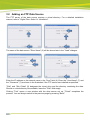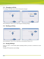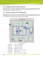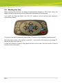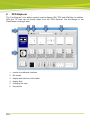
1
PLATEPATCHER 14.0
USER MANUAL
09.07.2014
PlatePatcher 14.0
© Copyright 2014
Esko-Graphics Imaging GmbH, 25524 Itzehoe, Germany
All rights reserved. This document and all information and instructions contained herein are the property
of Esko-Graphics. These documents contain the product descriptions according to their current state at
the time of publication, but no responsibility whatsoever is taken for the correctness of this information.
Based on the information in these documents, guarantees will neither be granted nor uprated.
Furthermore, Esko-Graphics will not guarantee the correctness of information in illustrations showing the
usage of the products or provided with the software, nor will Esko-Graphics guarantee the results when
using the software. Esko-Graphics will accept no responsibility for direct, indirect, consequential or latent
damages caused by using the software or by making use of the information contained herein, or by
failing to do so.
The technical data contained herein and the content of this manual are subject to change without prior
notification. Revisions which point out such changes and/or supplements may be issued from time to
time.
Without express written consent, no part of this document may be reproduced, transferred, electronically
stored or published, irrespective of the reasons and irrespective of the method or means used, i. e.,
electronic, mechanical, by printing, microfilm, etc.
These documents replace all previous versions.
Grapholas® is a registered trademark of Esko-Graphics Imaging GmbH.
Cyrel®, Cyrel® Digital Imaging System and Cyrel® Digital Imager (CDI) are registered trademarks of
DuPont.
Microsoft and the Microsoft Logo are registered trademarks of Microsoft Corporation in the U.S. and
other countries.
The Esko-Graphics software may include the "RSA Data Security, Inc. MD5 Message-Digest Algorithm".
JDF and the JDF Logo are trademarks of the CIP4-Organisation. Copyright 2001 The International
Cooperation for the Integration of Processes in Prepress, Press and Postpress (CIP4). All rights
reserved.
Java and all Java-based trademarks and logos are trademarks or registered trademarks of Sun
Microsystems in the U.S. and/or other countries.
Some parts of this software use technologies of JGoodies, Barbecue (Copyright 2003, International
Barcode Consortium), and Jakarta (licensed by Apache: www.apache.org/licenses/LICENSE-2.0.txt).
All other product names are trademarks or registered trademarks of their respective owners.
2
PlatePatcher 14.0
Table of Contents
1
SYSTEM REQUIREMENTS ............................................................................................................................. 5
2
DIGITAL FLEXO SUITE SERVICE ..................................................................................................................... 6
2.1
FIRST START-UP OF THE SOFTWARE ...................................................................................................................... 6
2.2
ENTERING THE LICENSE KEY ................................................................................................................................. 6
2.3
SETTING THE LANGUAGE ..................................................................................................................................... 7
3
MANAGING DATA SOURCES ........................................................................................................................ 8
3.1
ADDING A LOCAL DATA SOURCE ........................................................................................................................... 8
3.2
ADDING AN FTP DATA SOURCE............................................................................................................................ 9
3.3
CHANGING AN ENTRY ....................................................................................................................................... 10
3.4
DELETING AN ENTRY ........................................................................................................................................ 10
3.5
SAVING SETTINGS ............................................................................................................................................ 10
4
PLATEPATCHER ......................................................................................................................................... 11
4.1
SETTING THE PLATEPATCHER OPTIONS ................................................................................................................ 12
4.1.1
4.1.2
4.1.3
4.1.4
Adding Settings ............................................................................................................................... 12
Changing Settings ........................................................................................................................... 12
Deleting Settings ............................................................................................................................. 12
Possible Settings .............................................................................................................................. 13
4.2
REGISTER AND MOUNTING MARKS FOR PLATEPATCHER ......................................................................................... 17
4.3
SELECTING TECHNICAL INKS ............................................................................................................................... 18
4.4
EDITING A JOB ................................................................................................................................................ 19
4.5
MULTI-PATCH MODE....................................................................................................................................... 25
4.6
CUTTING LARGE PLATE PIECES ........................................................................................................................... 26
4.7
"PLOT & CUT" - "DRILL" .................................................................................................................................. 27
4.8
"PREMOUNT": MOUNTING WITH THE CDI .......................................................................................................... 29
4.8.1
Recommended Working Mode ........................................................................................................ 32
4.9
MACROFLEX ................................................................................................................................................... 33
4.10
AV OPTIMOUNT ............................................................................................................................................. 33
4.11
ZERO POINT FOR AV OPTIMOUNT, MACROFLEX AND HEAFORD ............................................................................... 33
4.12
LOADING TIF FILES .......................................................................................................................................... 34
4.13
WRITING TIF FILES .......................................................................................................................................... 34
4.14
OUTPUT DIRECTORIES ...................................................................................................................................... 34
4.15
JOB INFORMATION........................................................................................................................................... 35
4.16
LOADING IMAGES VIA "DRAG & DROP" ............................................................................................................... 35
5
KONGSBERG XL GUIDE .............................................................................................................................. 36
5.1
REGISTRATION ................................................................................................................................................ 36
5.2
SETTING THE TOOLS ......................................................................................................................................... 37
5.2.1
5.2.2
5.3
Setting the "Bevel Knife" (45° Knife)................................................................................................ 37
Drill Setup ........................................................................................................................................ 38
OPTIMISATION ................................................................................................................................................ 38
3
PlatePatcher 14.0
5.4
ASSIGNMENT OF THE OUTPUT CHANNELS ............................................................................................................ 39
5.4.1
Output Channels of the PlatePatcher .............................................................................................. 39
5.5
ALIGNING THE PLATE ON THE KONGSBERG TABLE .................................................................................................. 40
5.6
STARTING THE JOB ........................................................................................................................................... 42
6
DFS EXPLORER ........................................................................................................................................... 43
6.1
CHANGING THE VIEW ....................................................................................................................................... 44
6.2
ROTATING, MIRRORING AND DELETING FILES ....................................................................................................... 44
6.3
DISPLAYING DATA ........................................................................................................................................... 45
7
ACM VIEWER ............................................................................................................................................. 46
8
SUPPORT ................................................................................................................................................... 48
4
PlatePatcher 14.0
1
System Requirements
The following minimum requirements must be met:
•
Intel Dual Core 2 processor
•
2 GB RAM
•
network board
•
screen resolution of 1280 x 1024 pixels
•
CD-ROM drive
•
32-bit operating system
•
Microsoft Windows XP
•
disabled firewall
•
disabled UAC (User Account Control)
•
FTP server installed and enabled
(Only in combination with Grapholas 10.3)
•
Grapholas 10.3 on the CDI
•
Grapholas 12.1 on the CDI with Full HD Flexo or Pixel+
The following configuration is recommended:
•
Intel i7 processor
•
8 GB RAM
•
Hard drives: 512 GB SSD
•
1 GB network board
•
Microsoft Windows 8 – 64 bit
•
disabled firewall and user account control (UAC)
•
Grapholas 14.0 on the CDI
5
PlatePatcher 14.0
2
Digital Flexo Suite Service
The following services are automatically installed with the Digital Flexo Suite:
•
Esko CDI Service - "bsl_cdisvc"
•
Esko http - "bsl_http" (port 5580)
The following programs must be enabled:
•
gravurd
•
cmotsim
2.1 First Start-Up of the Software
The "PlatePatcher" analyses the image content of LEN or TIF files and applies register marks to
the determined areas. A coordinate file is created for automatic mounting. A printout of an ACM
or EPS file is used for manual mounting.
The "Viewer" is used to display and measure the LEN/TIF files. The angle and the rasterization
can also be measured.
All important settings are copied over during an update. If the software is being installed for the
first time, the network settings must be set.
2.2 Entering the License Key
During initial installation or when updating from an older version, the license key must be
entered to start the "Merger":
The ESKO-Service provides a serial number for this "ProductID" which needs to be entered in
the "Serial Number" field and confirmed by ENTER. The license can be subsequently changed
with the "New License" program in the Windows Start Menu under "Esko - Digital Flexo Suite System".
6
PlatePatcher 14.0
2.3 Setting the Language
The language can be changed in the Windows start menu under "ESKO – Digital Flexo Suite System – UI Language":
7
PlatePatcher 14.0
3
Managing Data Sources
The image data can be loaded from the local hard drive, over a network release, or via FTP.
With regard to data security, transmission via FTP protocol is to be preferred over network
release.
The path entered during installation for the "User Data" is already released as a network drive.
Additional data sources can be set up under "Edit – Data Source".
3.1 Adding a Local Data Source
Local data sources can be located on the hard drive of the computer or accessible in the
network via "share" function.
The name of the data source "Drive Name" (3) will be shown later in the "Load" dialogue.
"Disk" and "Sub Folder" (6) designate the drive letter and the directory containing the data.
Clicking "Test" (7) opens a new window with the data source set up. "Finish" (9) completes the
process. You can always switch to the previous page by pressing "Back".
8
PlatePatcher 14.0
3.2 Adding an FTP Data Source
The FTP server of the data source requires a virtual directory. For a detailed installation
manual, refer to "Digital Flexo Suite 101 Installation".
The name of the data source "Drive Name" (3) will be shown later in the "Load" dialogue.
Enter the IP address or the network name in the "Host" field (6). Enter the "User-Name" (7) and
the "Password" (7) as shown in the illustration if the FTP server was installed as specified.
"Disk" and "Sub Folder" (9) designate the virtual drive and the directory containing the data.
Should no virtual directory be available, leave the "Disk" field empty.
Clicking "Test" opens a new window with the data source set up. "Finish" completes the
process. You can always switch to the previous page by pressing "Back".
9
PlatePatcher 14.0
3.3 Changing an Entry
The settings of the data source can be subsequently changed.
After selecting the "Drive" (3), you can change the following settings.
3.4 Deleting an Entry
After selecting the "Drive" (3), you can remove it by pressing "Remove" (4).
3.5 Saving Settings
Exiting via "Quit", a new window opens requesting whether you want to overwrite the current
settings.
Pressing "OK" saves the current settings.
10
PlatePatcher 14.0
4
PlatePatcher
opens the PlatePatcher in a new window.
The PlatePatcher automatically searches the LEN or TIF files for free areas to cut out the
remaining image content. Depending on the output device, the relevant files will be created for
subsequent mounting.
For digital mounting, a camera and a mounting file are used to mount the plate pieces with
mounting marks on the mounting film. The accuracy is very high.
For analogue mounting, a printout or mounting pins are used to manually mount the plate
pieces on the mounting film. The accuracy is low.
Digital output devices:
• "AV-Optimount"
round mounting and flat mounting possible
• "Macroflex"
flat mounting
• "Heaford"
flat mounting
• "PreMount" on CDI
flat mounting - exposure of the plate pieces on the CDI
Analogue output devices:
• "ACM-PLOT"
cutting and labelling of mounting film
• "EPS PLOT"
film labelling
• "Drill"
drilling holes into the mounting film and the plate pieces
• "Bieffebi"
labelling of film and camera control
11
PlatePatcher 14.0
4.1 Setting the PlatePatcher Options
Templates are created for the PlatePatcher options by calling up the "PlatePatcher Workflow
Editor…" under "Edit":
For each mode, the "PlatePatcher Workflow Editor" shows a preview with the currently set
values. Irrespective of the output, an ACM file is generated so that the mounting film on the
Kongsberg table can be cut and labelled.
On either side, different values are set:
"Mount":
setting of the output device
"Carrier Sheet": setting of the mounting film
"Output":
setting of the file output
4.1.1 Adding Settings
By selecting "New" (1), a new window appears in which you can enter a name for this setting.
"OK" confirms the input. The new setting is automatically selected.
Adjust the required settings and save them by pressing "Save" (1).
4.1.2 Changing Settings
Select the setting (2) and change it. Press "Save" (1) to save the setting.
To not lose existing settings, the new settings can be renamed by pressing "Save as" (1).
4.1.3 Deleting Settings
Select the setting (1) and delete it by pressing "Delete".
12
PlatePatcher 14.0
4.1.4 Possible Settings
Each mounting device can be adjusted individually. Before starting the device for production,
these properties must be set and checked during a test mounting. For this purpose, a job which
is unsymmetrical in X and Y direction is to be used.
Mount:
"Default Frame": Minimum distance between the patch and the edge of the created image. If
this is set too small, a collision can occur during automatic grouping.
"Film Gap": Gap between the register mark and the edge of the image section. This area is
also used for subsequent cuts using the 45° knife.
"Patch Distance": Defines the distance between two image elements by compiling them
automatically in one grouping. Elements with a larger distance are separated.
"Vertical Distance": Height above which additional register marks are added to the patch.
"Export - LEN / TIF": The resulting images are exported directly into directories instead of
transmitting them to the Merger. An extra licence is required to output TIFs.
"Front Text": The patch labelling is not exposed together with the plate but craved into the
frame area using the knife on the Kongsberg table. This labelling needs not to be removed
afterwards.
"Cut RegisterMarks": For Plot output, the register marks can be carved with a knife. This way,
is not necessary to remove the marks later on.
"Crop Marks": Adds guides to the corners of each output file which can be used for manual
cropping.
"Force 4 Marks": Always creates four marks in Plot&Cut mode.
13
PlatePatcher 14.0
"Ignore Collision": Writes register marks even if they overlap with image data. In this case, the
marks should be manually moved to a position where they will not interfere later when printing
the image.
Carrier Sheet:
"Camera Distance": Determines the minimum camera distance for the selected mounting
device. A higher value creates wider patches.
"Mount Offset": With AV Optimount, an upper and lower image border is inserted in the
grouping window. This is required when register marks must be positioned above or below the
image. The entire co-ordinate plane is moved by this value, which results in a difference to the
original gripper distance during the mounting.
"Font Size": Size of the texts on the mounting film.
"2nd Font Size": Size of the job name. When entering "0", "Font Size" is used.
"Register Mark File": You can select the mounting marks from a list. An overview can be found
in the appendix.
"Regmark Scale": Enlarges the mounting marks on the mounting film significantly.
"Opaque Tape": Creates lines on the mounting film outside the image file in Plot&Cut mode so
that it can be mounted more easily. This option should be used in combination with "Force 4
Marks"!
"Top Grip": Mirrors the output coordinates in the circumference direction. This option has to be
activated when the image data is mirrored after patching, which is the case with some other
types of CTP exposure units.
"Emulsion down": Rotates the output coordinates by 180°.
"Add Job Name": Automatically inserts the file name under each output file.
14
PlatePatcher 14.0
"Origin Bottom Left": Places the origin of the coordinates at the bottom left when using
Macroflex. The mounting is usually performed from the middle. In this case, this option must not
be activated.
"Cut Carrier Sheet": Automatically cuts the mounting film on the Kongsberg table after the
register marks or mounting holes and the carton cut have been drawn. Depending on the plate
distortion, the gripper distance and the height of the mounting film are automatically counted
back.
"Reference to technical ink": When activated, the centerline - and for Macroflex also the
baseline - is related to the cut.
"Landscape": The ACM file for the Kongsberg table is rotated by 90°. This is necessary to, for
example, cut a 4260 plate on an XL 20 table.
Style - Premount
"Carrier Sheet Width" and "Carrier Sheet Height": Specifies the desired output format of the
mounting film for the PreMount output (see "PreMount").
"Post Cut": Distance between the finishing cut and the edge of the plate piece for PreMount.
The value "-5" is also suitable for thick plates. The finishing cut removes the edge around the
patch which was created during UV exposure.
"Pre-Mount Gap": Enlarges image sections in the mask for plate mounting when using
PreMount.
"Minimum Width" and "Minimum Height": Enlarges small plate pieces to this minimum size
at "PreMount" output.
"JBar offset": For "PreMount" output, the mounting film is labelled. This value indicates the
distance of this label from the lower edge of the mounting film, so it will not be covered by the
mounting rail.
"Do Post Plot": If available, the carton cut for PreMount can be written subsequently on the
film. It is not written on the mounted plates.
15
PlatePatcher 14.0
"Do Post Cut": The UV exposure creates an elevated edge around each "patch". This edge is
removed in the last step using the 45° knife. The unexposed plates are cut using the straight
knife.
If this option is deactivated, a mask is automatically created for the UV exposure. The
unexposed plates are then cut using the 45° knife.
Output:
"Mount Target Folder": Is the folder where the mounting file is stored.
"Patch Target Folder": Is the folder where the plate pieces are stored when "Export" is
selected.
"Plot Device": Sets the output format for the plotter. ACM is always available for the output on
the Kongsberg table. EPS output requires an extra license.
"Technical Ink": In order to be able to identify the technical ink (carton cut) later on, the name
must be determined according to the file name (for example, file name_PLOT).
"MAT Info": As an option, the name of the XL Guide "Job Setups" which will be automatically
loaded on the Kongsberg table can be entered in this field.
"Crop Patches": If areas are grouped in different separations in multi patch mode, the resulting
patches are reduced to the required size. If this function is deactivated, patches of the same
size are created.
"Multiple mount files": Creates a file with coordinates for each separation. If this function is
deactivated, all coordinates are written into one file.
"Dual Output": When this option is activated, an additional Heaford mounting file is created for
the Macroflex output and the AV output.
"Round Mounter": For AV Optimount, the coordinate file is counted back to 100%. The
distortion values are entered on the mounting device.
"Old Macroflex Format": Writes the DHM file for older versions of Macroflex without line break.
"Count Separations": Enumerates the separations in the Macroflex output file.
"Patch Multi-Line": Creates three lines in the Macroflex output file for each patch. In this way,
the upper and lower register marks can be used even with older Macroflex models (see "Vertical
Distance").
16
PlatePatcher 14.0
4.2 Register and Mounting Marks for PlatePatcher
17
PlatePatcher 14.0
4.3 Selecting Technical Inks
Since the Esko Automaton Engine 12, LEN files can be provided with the technical ink. The CF2
file is no longer used in this case.
Depending on the application, the name of the technical ink may be different or several
technical inks may exist. For this reason, one or more technical inks can be selected.
When a job is loaded in the PlatePatcher, the LEN files are searched for technical inks and a
warning message appears if an unregistered ink is included.
The "Channel-Editor" displays the currently selected file with the included technical inks:
A left mouse click on the CAD channel (1) updates the display (2).
In the "Selected" (3) area, the desired CAD channels can be selected; this selection is then
saved in the selected PlatePatcher setting using "Save" (4). Different technical inks can be
assigned to each PlatePatcher setting.
18
PlatePatcher 14.0
4.4 Editing a Job
Independent of the mounting machine, patching is always carried out in the same sequence.
The following job "GaelicGhost" with 4 colours plus the technical ink and the CF2 file of
ArtiosCAD for the carton cut is used to explain the patching of image data.
The PlatePatcher requires the job data in the mounting alignment.
The file names are used to assign the technical ink and the CF2 file to the job. As with the
"Merger", the names may not include special characters. The ink designation may not include
spaces or underscores:
Job:
GaelicGhost_c.len - GaelicGhost_k.len - GaelicGhost_y.len - GaelicGhost_1605.len
Technical ink:
GaelicGhost_PLOT.len
CF2 file:
GaelicGhost.cf2
The start is carried out in the "Preview" mode. The "Merger" remains in the background but
cannot be used.
19
PlatePatcher 14.0
1
Selecting the mounting settings:
2
Load the job.
Select only one separation, then confirm it with "OK" or double-click the file to load
it. The other separations and control files are automatically copied into the working
directory and displayed.
3
Check if the technical ink (P) and the CF2 file (T) were loaded. If these files are
missing contrary to expectations, check the file names.
20
PlatePatcher 14.0
In some cases, no CF2 file is required since the cutting file is already included in the
LEN file. If an error message is displayed, the technical color is to be added as
described previously.
4
By selecting "View…", the entire job is opened in the "Bitmap-Viewer".
5
Clicking on "Clear" removes the images from the display, and the options can be
selected again. This step does not delete any data on the storage medium.
6
Under "Separations", the "Single" option is to be selected to patch single
separations. "Patch Distance" defines the distance between two image elements by
compiling them automatically in one grouping. Elements with a larger distance are
separated.
7
Select the separation. A preview is displayed in the main window.
8
By selecting "Analyse image", the image is analysed and displayed in the grouping
window. You can also start the analysing process by double-clicking the respective
separation.
"Close" closes the PlatePatcher.
7
Clicking on the eye next to the ink in the table activates or deactivates the display.
21
PlatePatcher 14.0
8
Several patches can be selected by pressing the "Ctrl" button and the left mouse
button simultaneously and then grouped by clicking on "Group" (12) or "g".
Alternatively, you can also use the left mouse button to pull a lasso around several
"patches".
Press Ctrl + a to mark all plate pieces.
9
Overlaying plate pieces are marked in red and listed in the information display (11).
10 Collisions of marks with image data are highlighted with an exclamation mark. The
patches can be created but the mounting marks will not be drawn in order to not
change the image content.
11 The information field displays the area saved in cm² and as a percentage, the
number of plate pieces and the errors caused by overlapping plate pieces or
mounting marks.
12 Marks can be moved subsequently. Clicking on the mounting mark once changes
the colour to yellow and a green frame is shown. The mark can be moved
horizontally by holding down the left mouse button in the green frame.
Another click on the yellow mark changes the colour to red. The mark can now be
moved vertically with the left mouse button pressed on the mark. The opposite mark
is automatically moved simultaneously.
13 Hidden elements are marked with a cross.
14 The arrangement of the plate pieces and the number of register marks can be
changed as follows:
22
PlatePatcher 14.0
groups the plate pieces or ungroups them.
automatically inserts an additional mounting mark between the
marks in the centre. To this end, the plate piece must be marked.
inserts an additional drill hole at any position.
After actuating this button, you can select the position by clicking
the left mouse button.
removes the selected register mark.
sets the mounting marks for the marked patch back to their
original positions.
analyses the currently selected patch with the reset "Patch
Distance".
cuts a large plate piece. After selecting the plate piece, this icon
is activated. Then left-click the desired cut position within this
plate piece. Cutting is not possible in the frame areas.
automatically removes all overlays.
activates the zoom function.
Press and hold the left mouse button to select an area to be
zoomed in.
As an alternative, you can use the mouse wheel.
displays the entire image.
"Jobname" is used to add the file name to the lower edge of the patch.
"Hide" or "x" hides one or more marked patches. This option can be used to hide
unnecessary elements.
"Dye Cut" activates or deactivates the output of the technical ink
23
PlatePatcher 14.0
15 The distortion "Rip Scale" is automatically read from the LEN file. For TIF files or if
the distortion information is missing, the distortion is calculated based on the size
difference between the CF2 file and the technical ink. If the information is indefinite,
100.0 is displayed as value but can be changed manually.
With some mounting devices, "Mount Scale" can be used to scale the output file.
This is not possible if "Cut Mylar" was selected in the PlatePatcher settings.
"Rotate" rotates all output files by 90°.
"Negative" inverts all output files for film exposure units because negative images
cannot be edited in PlatePatcher.
The settings "Negative" and "Rotate" can only be changed in the first separation
and are then valid for the entire job.
16 The size of the mounting film can be changed as follows:
The position of the image data can only be set for "PreMount" and "Plot&Cut"
output.
If these values are not changed, the size of the loaded image file will be used.
Depending on the settings, the plate distortion will be taken into account.
The image file is automatically positioned in the centre. As soon as the "Mylar
Width" is changed, the gap between the image and the left film side is calculated
anew in the "Left Gap" field.
The centerline, which will be drawn at a later time, can be moved in the "Center
Offset" field.
The automatically calculated gripper distance can be changed in the "Gripper" field.
This requires consultation with the design department.
17 "Create Patches" cancels the grouping. The requested files are created and
transmitted to the "Merger" or a directory. This process may take several minutes,
depending on the complexity. Collisions of register marks with image elements and
overlays are displayed in a corresponding message window. In general, no image
data is overwritten.
"Close" closes the grouping view without creating files.
24
PlatePatcher 14.0
All separations are edited in sequence. Select the next separation (5) and repeat the process.
Mounting files are always updated when data is created so that all required data is available at
the end.
4.5 Multi-Patch Mode
All separations are displayed and edited together. The selected base separation "Master" is not
cut and includes the register marks of all other separations after editing. All other separations
are based on this base separation on the mounting device at a later time.
If "Multiple" is selected, the table with the separations extends:
"Master" selects the base separation from the loaded job. The master must still have sufficient
free space to allow the register marks of the other separations to be placed.
"Reference" selects a separation which is not to be cut. For mounting, mounting marks are
placed to the left and the right of the image.
"Patch" displays the separations which will be analysed.
Set the "Patch Distance" and open the grouping window by selecting "Analyse image…".
The same editing options as in the "Single Patch Mode" are available.
As opposed to "single patching", collisions can now also occur on the "Master". As the
separations are still mounted separately, overlays between different separations no longer
occur.
Showing and hiding separations makes it easier to keep an overview when working on complex
jobs. The reference separation is labelled "ref", the master separation "Master".
25
PlatePatcher 14.0
4.6 Cutting Large Plate Pieces
cuts a large plate piece.
After selecting the plate piece, this icon is activated. Then left-click the desired cut position
within this plate piece. Cutting is not possible in the frame areas.
New positioning marks are added to each side apart from the seam. To manually undercut this
seam, the two plate pieces overlap. In addition, a mark is added to the top and the bottom of the
seam which can be used for manual cutting.
26
PlatePatcher 14.0
4.7 "Plot & Cut" - "Drill"
For "Plot" or "Drill" mounting, the PlatePatcher creates an ACM file for each separation for the
Kongsberg table. These ACM files include data for labelling, drilling and cutting the mounting
film.
The carton cut, the mounting marks and the guides are drawn first. Then the mounting film is
cut to the required size. For the "Drill" output, holes will be drilled beforehand.
As of version 10.0, the output size of the mounting film for the "Plot & Cut" output is no longer
determined by the size of the image data. For the "Drill" output, the LEN file and the film size
must still be identical.
The "Cut Mylar" option must be selected in the settings. This prevents the elements to be
placed outside the mounting film.
In addition, the plate distortion for the gripper distance (2) and for the mounting film height (1)
are counted back to 100%. The calculated plate distortion should be checked in the grouping
window of the PlatePatcher.
The centerline refers to the center of the loaded image, except if the "Use Cut" option is active.
In this case, the centerline refers to the cut.
Green drill holes (2 & 3) can be moved in all directions in the green frame by pressing and
holding down the left mouse button and deleted by selecting "Remove". Additional mounting
marks in the frame can only be moved to a certain extent.
27
PlatePatcher 14.0
The frame is automatically filled with drill holes or mounting marks (2). The parameter
"Vertical Distance" determines the distance.
Drill holes can be added subsequently at any position (3). For this purpose, select icon 4 and
left-click on the position of the new drill hole.
Additional mounting marks can only be added between the two marks in the center of a patch
(6). To this end, mark the patch and click on icon 5. Marked holes can be removed by clicking
icon 7.
In order to mount the plate pieces, additional drilling information is added to the LEN files so
that the "Merger" can transmit the drill holes to the Kongsberg when sending the plate job. The
option XL CUT must be activated. Each plate piece will have its own drilling pattern in order to
avoid confusion during the mounting of the plates. Depending on the size, three or four holes
will be drilled. These hole positions cannot be moved in the PlatePatcher.
Blue drill holes are automatically added (1). These holes cannot be changed in order to avoid
confusion during the mounting.
The number of possible positions of the holes is defined by the hole size and the frame around
the plate pieces. If too many small plate pieces were created, it is possible that there are not
enough positions for all of them. A message window is displayed. In this case, either the frame
or the plate pieces must be enlarged by grouping.
Setting-up the drill hole size must be carried out by a service technician at the location. The
"Flexo Drill Toolkit" is required for the Kongsberg table.
28
PlatePatcher 14.0
4.8 "PreMount": Mounting with the CDI
For "PreMount" mounting, the PlatePatcher creates plate pieces which are cut out of the
unexposed plate. These will be positioned on the mounting film which will then be mounted in
the CDI. The mounting accuracy is very high.
29
PlatePatcher 14.0
1
Processing the image data in the PlatePatcher and output of the corresponding LEN
files to the "Merger" or in a folder. For each separation, an ACM file containing the
cutting and mounting information will be output.
If the carton cut is to be drawn subsequently, the plate pieces are to be edited using
the 45° knife or the mounting film is to be cut to the desired size, an ACM file with
the "_POST" extension will be created for each separation in addition. This file is
used to edit the finished mounting film again just before delivery.
If "Do Post Cut" is deactivated, a mask with the extension "_Mask" is created and
used to cover the edges for the UV exposure after imaging. This prevents the
formation of an elevated edge.
2
Drawing information for mounting and cutting of the films. The film placed on the
Kongsberg table should always be a little larger than the desired size.
The 2-point registration is also used in this case so that the width of the mounting
film is displayed right at the beginning.
Due to patent restrictions, the positions of the plate pieces must not be drawn on
the mounting film. These positions are drawn on another film and then placed under
the mounting film to mount the plate pieces. The individual channels are selected on
the Kongsberg table.
3
Sending the plate pieces for cutting the unexposed plates on the Kongsberg table.
Nothing is sent to the CDI. For this purpose, the PreMount drum must be selected
which has been set up by an ESKO technician.
The plate pieces are labelled at the top for subsequent mounting.
4
Sending the "Master" file to the CDI. The file is automatically centred and positioned
with the desired gripper distance. For this purpose, the PreMount drum must be
selected.
30
PlatePatcher 14.0
In addition, the thickness of the adhesive tape, the mounting film (Mylar) and the
support must be entered.
Since the thickness change is known now, the plate type in use can be used as for
normal jobs.
5
Positioning the unexposed plate pieces on the mounting film.
6
Mounting the mounting film on the CDI. The start position is preset.
7
The finished mounting film can be cut to the desired size just before delivery.
The "_POST" file is loaded and the two corners of the mounting film (1 + 2) are
registered using the camera. This accuracy is very important in case the mounting
film is cut to the correct size afterwards (4).
If the plate pieces are not masked during the main exposure, the exposed edges
can be removed in this last step using the 45° knife (3).
In addition, the carton cut can be drawn. In this case, the carton cut is not drawn
onto the mounted plate pieces.
31
PlatePatcher 14.0
4.8.1 Recommended Working Mode
The mounting effort on the CDI is minimised if the mounting film is always cut to the entire drum
size (50 x 80: 2030 mm x 1270 mm).
In order to save mounting film and minimise the washer time, the entire circumference can be
used optionally. This is obtained by setting the width of the mounting film to "0".
If it is not required to trim the finished mounting film, the unexposed plates should be cut using
the 45° knife and the edges should be masked before the exposure using adhesive tape. For
this purpose, a "Film Gap" must be entered in the PlatePatcher corresponding to the thickest
plate. Otherwise, the data of the unexposed plates cannot be used in the "Merger" using the 45°
knife.
The speed of the 45° knife should be set to "5" when cutting the unexposed plates. In addition,
a good vacuum is required. When small plate pieces are concerned, at least one side should be
taped.
If it is not required to mask the edges, the unexposed plates should be cut using the straight
knife so that the exposed edge can be removed afterwards using the 45° knife.
In general, it is recommended to leave a margin around each plate piece of at least 15 mm. The
thinner this margin, the more accurate the plate pieces must be positioned on the mounting film.
32
PlatePatcher 14.0
4.9 Macroflex
All coordinates of the Macroflex output refer to the loaded image. When a cutting file is
available, the "Use Cut" option can be activated. When activated, all coordinates refer to the
baseline and to the position of the cut.
4.10 AV Optimount
To be able to place registry marks underneath or above the image, a lower or upper edge is
required respectively. This edge is set up with "Mount Offset" as described in the mounting
settings.
This creates an offset in circumferential direction which has to be subtracted from the desired
gripper distance (black area) for the mounting:
Example:
"Mount Offset":
20 mm
Desired black area:
100 mm
Required offset:
80 mm (100 mm – 20 mm)
4.11 Zero Point for AV Optimount, Macroflex and Heaford
The PlatePatcher places the zero point in the bottom left corner of the ripped LEN or TIF file or
the cut. If, in addition, job information and screen wedges are set in the customer's job, an offset
to the desired zero point is created in the X and Y directions. In most cases, this offset varies,
which may lead to incorrect mounting.
The required zero point (1) is moved in the wrong design (3). In addition, the screen wedge
outside the image width displaces the mounting centre (2). This can be avoided by extending
the image symmetrically to both sides.
33
PlatePatcher 14.0
4.12 Loading TIF Files
TIF files are normally read from left to right. Because of the technical requirements of imaging,
Digital Flexo Suite reads TIF files from the bottom to the top. This rotates the display
accordingly:
The alignment of the images in PlatePatcher has to match the alignment in mounting. The
image has to be rotated 90° in the design for exporting.
4.13 Writing TIF Files
TIF files can be exported directly from PlatePatcher using the TIF export function. The TIF data
is exported with the alignment as described in the previous chapter which results in a rotated
display in other programs.
The software of some of the CTP exposure units available on the market displays the TIF data
with the same alignment as in the design, even though the data has to be read from the bottom
to the top for imaging.
This is caused by the different alignment between drum and image. The "Merger" assumes that
the height corresponds to the circumference of the drum and the width corresponds to the width
of the drum. The drum may be shown rotated by 90° in the displays of other CTP exposure
units.
4.14 Output Directories
In order to output mounting and preview files, the PlatePatcher needs predefined directories.
The mounting settings can be called up under "Options – Preferences – Folder" in the "Merger".
The PlatePatcher options provide more settings.
34
PlatePatcher 14.0
4.15 Job Information
For every job, an HTML file with the original file name is saved in the "Patcher Redo" directory.
All important information concerning the job is stored in that directory. The output directory
"d:\files\output\PatcherRedo" is preset.
4.16 Loading Images via "Drag & Drop"
Image files (LEN and TIF) can directly be dragged into the "PlatePatcher" from the Windows
Explorer or from the "Len Explorer". First, the data is copied into the working directory, then it is
loaded.
35
PlatePatcher 14.0
5
Kongsberg XL Guide
If PreMount output or 6064-point registration is used, at least XL Guide version 4 must be
installed on the Kongsberg table.
If an ACM file created with XL CUT or PlatePatcher in XL Guide is opened, the global setting is
automatically changed to "Ctp Flexo".
The cut and sequence optimisation is deactivated in this setting. If set in the Digital Flexo Suite,
"Job Setup" is loaded additionally.
The interface of the version 6064 slightly changed. It is no longer necessary to select the
positions of the register marks. Furthermore, the register wizard is compiled in one window.
5.1 Registration
By clicking on this icon, a new window with the option to change the registration
behaviour is opened:
Under "Register mark input", the "From input file" option (1) must be activated, otherwise the
plate cannot be cut correctly.
Under "Transformation", the "Offset and rotation only" option (2) must be selected to ensure that
the cut is not distorted during the registration.
It is possible to register using the laser pointer or the camera (3). The cutting accuracy of the
camera is higher.
36
PlatePatcher 14.0
5.2 Setting the Tools
The knives can be set in the "Job Setup" window which is opened via the "Options" menu. Each
element in the ACM file is assigned to its own channel (line) (1). The speed and the acceleration
(3) must be determined on site.
Since Digital Flexo Suite 7.5, the ACM file contains more channels which can be selected at the
Kongsberg table.
Therefore, the "No tool = Ignore" (2) option must be activated.
5.2.1 Setting the "Bevel Knife" (45° Knife)
Before using the "BevelKnife" (45° knife), the option "Single cut" must be activated in "Job
Setup" under "Extended Setup …" as the step will otherwise not be performed properly. The
knife speed for the "BevelKnife" should not exceed a value of "30".
37
PlatePatcher 14.0
5.2.2 Drill Setup
In order for the drill to drill - independent of the plate thickness - to the table top, the drilling
depth must be limited by entering "T" (1). The speed should be set to "1000" (2).
5.3 Optimisation
To use the cutting lines at best, the "Sequencing" option should be activated in the XL Guide
settings:
38
PlatePatcher 14.0
5.4 Assignment of the Output Channels
Each element in the ACM file is assigned to its own channel (line). The channels cannot be
defined or hidden in the Digital Flexo Suite. This has the advantage that the operator of the
Kongsberg table can change the output quickly.
5.4.1 Output Channels of the PlatePatcher
Depending on the selected output device, the PlatePatcher uses up to nine channels. Only the
required channels are set up in the "Job Setup" window. All other channels must be set to "No
Tool". In addition, the "No tool = Ignore" option must be activated.
• Channel 1:
contour of mounting film
• Channel 2:
contour of the image
• Channel 3:
contour of the "patch"
• Channel 4:
labelling of the "patch"
• Channel 5:
labelling of the mounting mark
• Channel 6:
mounting mark
• Channel 7:
centre line with arrow for gripper
39
PlatePatcher 14.0
• Channel 8:
job name
• Channel 9:
carton cut
• Channel 13:
drill holes for "Drill" mounting
• Channel 14:
mounting holes of the drum for "PreMount"
• Channel 16:
finishing cut of plate pieces for "PreMount"
• Channel 32:
"IGNORE"
5.5 Aligning the Plate on the Kongsberg Table
The positioning marks are normally on the operator’s side (1+2). Only if the alignment "Vertical"
+ "Landscape" has been deactivated, the positioning marks are on the right-hand side (3).
When activating the 3-point registration, a third positioning mark is placed on the opposite side.
The text for identifying the plate is always located between the first two marks.
If the "X-Mirror" (X) or "Y-Mirror" (Y) option for back labelling has been selected in the "Merger",
the plate is rotated accordingly.
As cut optimisation cannot be used for the 45° Knife, the plate should be fixed to the table as an
additional measure. To achieve a clean cut, this knife requires a special set-up.
40
PlatePatcher 14.0
41
PlatePatcher 14.0
5.6 Starting the Job
When importing the ACM file, the setting is automatically changed to "CTP Flexo". Here, the
register wizard is activated and some optimisation parameters are deactivated.
If the "MAT Info" field was filled in the "XL CUT" submenu, the file with the knife settings is
automatically loaded.
The setup of the plate is started by pressing the "I" button on the Kongsberg operating panel.
Move the laser pointer to the centre of mark No. 1 and confirm this position by pressing "I".
Repeat this step with mark No. 2.
If used, the camera is moved in the general direction of the mark, then the mouse is used to
click the centre of the mark.
42
PlatePatcher 14.0
6
DFS Explorer
The "Len Explorer" is an add-on product used to display LEN, TIFF and ACM files. In addition,
LEN and TIF files can be directly drawn from the "DFS Explorer" into the Merger or the
PlatePatcher via drag & drop.
1
menus for additional functions
2
file reread
3
display and selection of the folder
4
display filter
5
changing the view
6
file preview
43
PlatePatcher 14.0
6.1 Changing the View
The slider can be used to change the view from detail (far left) to large preview (far right).
In the detailed view, a left mouse click on the respective field sorts the table by name, date,
width, height, resolution or file size.
6.2 Rotating, Mirroring and Deleting Files
In the DFS Explorer, several files can be selected and rotated, mirrored or deleted with a right
mouse click.
44
PlatePatcher 14.0
6.3 Displaying Data
Double-clicking the file opens the Bitmap viewer for LEN or TIFF files and the ACM viewer for
ACM files.
45
PlatePatcher 14.0
7
ACM Viewer
This program is used to display and control the ACM files which were created by using the
Digital Flexo Suite.
After the Digital Flexo Suite installation, all ACM files are automatically linked to the "ACM
Viewer".
The distance between two points can be measured by using the right mouse button (hold
pressed) (1). The image content can be enlarged by using the mouse wheel (2) and moved by
using the left mouse button (hold pressed and pull) (3).
Double-click one ACM file and an additional window (4) will be opened. "Start" in the "Manual
Step" area (5) starts a simulation of the cutting and drawing process. In the "Settings" area (6),
the line thickness can be changed.
Additional information can be displayed in the "View" menu.
If the ACM Viewer of the Digital Flexo Suite is used, LEN files can also be displayed.
Cutting information of "Staggered Cut" and CAD information of Flexrip are displayed in addition.
46
PlatePatcher 14.0
Using the function "File – Overlay File", it is possible to place the according LEN or TIF file over
the ACM file. Holding the "Ctrl" button, you can move the contour of the ACM with the left
mouse button until both register marks are above each other.
Then you can check the cut.
Several LEN files are created when the output is performed on a CDI with ABS. A revision
of the images is no longer possible!
47
PlatePatcher 14.0
8
Support
To contact ESKO, please visit www.esko.com.
48