1
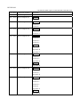
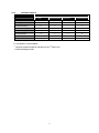
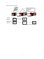
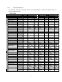
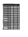
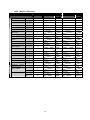
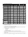
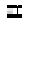
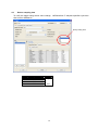
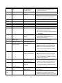
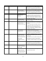
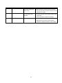
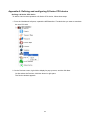
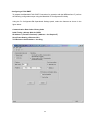
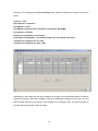
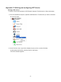
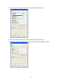
SAFETY PRECAUTIONS (Always read these instructions before using this equipment.) Before using this product, please read this manual and the relevant manuals introduced in this manual carefully and pay full attention to safety to handle the product correctly. The instructions given in this manual are concerned with this product. For the safety instructions of the programmable controller system, please read the CPU module user's manual. In this manual, the safety instructions are ranked as "DANGER" and "CAUTION". DANGER Indicates that incorrect handling may cause hazardous conditions, resulting in death or severe injury. CAUTION Indicates that incorrect handling may cause hazardous conditions, resulting in medium or slight personal injury or physical damage. Note that the ! CAUTION level may lead to a serious consequence according to the circumstances. Always follow the instructions of both levels because they are important to personal safety. Please save this manual to make it accessible when required and always forward it to the end user. [Design Instructions] DANGER When performing data changes or status control from the personal computer to the running PLC, configure up an interlock circuit outside the PLC system to ensure that the whole system will operate safely. In addition, predetermine corrective actions for the system so that you can take measures against any communication error caused by a cable connection fault or the like in online operations performed from the peripheral device to the PLC. CAUTION Read the manual carefully before performing the online operations (especially forced output and operating status change) which will be executed with the personal computer connected to the running CPU module. Not doing so can damage the machine or cause an accident due to misoperation. REVISIONS * The manual number is given on the bottom left of the back cover. Print Date * Manual Number Revisions Oct., 2008 BAD-804Q006-A0 First edition May., 2009 BAD-804Q006-A1 Addition Section 5.1 Nov., 2009 BAD-804Q006-A2 Correction Section 3.1 Section 4.1 Feb., 2010 BAD-804Q006-A3 Correction Section 4.1 Section 5.4 Sep., 2010 BAD-804Q006-A4 Correction Section 3.1 Section 4.1 Section 5.1 Addition Appendix A Appendix B Appendix C Jan., 2011 BAD-804Q006-A5 Correction Section 3.1 Section 4.1 Appendix A Addition Appendix D Jun., 2011 BAD-804Q006-A6 Correction Section 3.1 Section 4.1 Appendix D Mar., 2012 BAD-804Q006-A7 Correction Section 3.1 Section 4.1 Section 5.1 Section 6 Appendix A Addition Appendix E This manual confers no industrial property rights or any rights of any other kind, nor does it confer any patent licenses. Mitsubishi Electric Corporation cannot be held responsible for any problems involving industrial property rights which may occur as a result of using the contents noted in this manual. © 2012 MITSUBISHI ELECTRIC CORPORATION This book applies to the Mitsubishi Electric Corporation MESInterface IT product components and to all subsequent releases and modifications until otherwise indicated in new editions. Make sure you are using the correct edition for the level of the product. MITSUBISHI ELECTRIC CORPORATION PROVIDES THIS BOOK "AS IS," WITHOUT WARRANTY OF ANY KIND, EITHER EXPRESS OR IMPLIED, INCLUDING, BUT NOT LIMITED TO, THE IMPLIED WARRANTIES OF MERCHANTABILITY OR FITNESS FOR A PARTICULAR PURPOSE. Some states do not allow disclaimer of express or implied warranties in certain transactions therefore, this statement may not apply to you. This book could contain technical inaccuracies or typographical errors. Changes are made periodically to the information herein. Mitsubishi Electric Corporation. May make improvements and changes at any time to the product(s) and/or program(s) described in this book. When you send information to Mitsubishi Electric Corporation, you grant Mitsubishi Electric Corporation a nonexclusive right to use or distribute the information in any way it believes appropriate, without incurring any obligation to you. Contents Using Driver............................................................................................................................................1 1 Process for creating the CPU in Devices node ............................................................................1 2 Assumptions .................................................................................................................................1 3 SYSTEM CONFIGURATION AND SPECIFICATIONS ............................................................2 3.1 4 5 6 System Configuration ...........................................................................................................2 SPECIFICATIONS .......................................................................................................................4 4.1 Accessible Devices and Ranges.............................................................................................4 4.2 Device sampling time ..........................................................................................................13 4.3 Max number of accessible CPU module .............................................................................14 4.4 Device comment ..................................................................................................................15 SETTINGS AND PROCEDURE TO OPERATION ..................................................................17 5.1 Step1 Defining the MELSEC CPU .....................................................................................17 5.2 Step2 Checking CPU state .................................................................................................20 5.3 Step3 Modifying CPU state ................................................................................................20 5.4 Step4 Checking CPU performances ...................................................................................21 Error code ...................................................................................................................................22 Appendix A: Defining and configuring Q Series CPU device ..........................................................28 Defining a Q Series CPU device....................................................................................................28 Configuring a Q Series CPU .........................................................................................................33 Appendix B: Defining and configuring FX CPU device ...................................................................35 Defining a FX CPU device.............................................................................................................35 Configuring a FX3U ENET ...........................................................................................................38 Appendix C: Defining and configuring GOT device.........................................................................40 Defining a GOT device...................................................................................................................40 Configuring a GOT device .............................................................................................................43 Appendix D: Defining and configuring QnUDE(H) Series CPU (Built-in Ethernet) or L Series CPU (Built-in Ethernet) device ........................................................................................................45 Defining a QnUDE(H) Series CPU (Built-in Ethernet) or L Series CPU (Built-in Ethernet) device..............................................................................................................................................45 Configuring a QnUDE(H) Series CPU or L Series CPU ..............................................................48 Appendix E: Defining and configuring L Series CPU (CC-Link IE Field) device ..........................51 Defining a L Series CPU (CC-Link IE Field) device ....................................................................51 Using Driver This booklet provides the information for MELSEC PLC driver usage in MESInterface IT and clarifies the specification the driver supports. The MELSEC PLC driver is used to communicate between MESInterface IT and MELSEC Q PLC. MELSEC Q is not only one on the same base unit (whose communication is called local access) but also one on the another base unit via network (whose communication is called remote access). 1 Process for creating the CPU in Devices node The process to create the MELSEC CPU in Devices node, add new MELSEC CPU, define the type of CPU, and define of connection parameters. You can check the network the target CPU from the Workbench, even if the target CPU is not connected directly from Workbench but via relay CPU. Also in devices you can see the CPU status that information includes either CPU work or not work. Process The following lists the order of the steps to create and then test the CPU • Step 1:Defining the MELSEC CPU . This step describes how to add MELSEC CPU item. • Step 2:Checking MELSEC CPU state. This step describes how to check the MELSEC CPU states. The connection between Workbench and MESInterface core is also checkable • Step 3:Modifying MELSEC CPU state. This step describes how to modify the MELSE CPU state • Step 4:Checking MELSEC CPU performances. This step describes how to checking the performance of MELSEC CPU. 2 Assumptions Before you begin, make sure the following has occurred: •You installed an MESInterface IT module on the rack of a supported programmable logic controller. •You installed the Workbench on a computer that has TCP connectivity to the MESInterface IT module. •The Workbench was previously started and you have a user ID and password. 1 3 SYSTEM CONFIGURATION AND SPECIFICATIONS 3.1 System Configuration 3.1.1 Overall system configuration This section shows the overall system configuration when using the MESInterface IT with C Controller Module. This module is placed at middle of MELSEC equipment and IT system, and it manages FA system under it. MESInterface IT C Controller Module Q12DCCPU-V MODE RUN CF CARD ERR. CH3 SD/RD USER USB iQ Automation iQ Automation iQ Automation iQ Automation iQ Automation QCPU Multi-CPU QCPU Multi-CPU QCPU Multi-CPU QCPU Multi-CPU QCPU Multi-CPU QnPH QnPH Qn(H) Qn(H) QnUD(H) QnUD(H) QnUDE(H) QnUDE(H) QnUD(H) QnUDE(H) L02CPU/L26CPU-BT QnPH Qn(H) QnUD(H) QnPH/Qn(H)/QnUD(H)/QUTE QnUDE(H) FX3U(C)/FX3G QnUDE(H) GT16/GT15 QUTE QUTE QUTE L02CPU/L26CPU-BT 2 3.1.2 Basic System configuration 33 Base unit Power module Network module CPU module C Controller module CF card (MESInterface IT core) 1. CPU module Follow show the available CPU module as CPU module. CPU type QCPU (Q mode) CPU model name Basic model QCPU Q00CPU,Q01CPU High Performance model QCPU Q02(H)CPU,Q06HCPU,Q12HCPU,Q25HCPU Process CPU Q02PHCPU,Q06PHCPU,Q12PHCPU,Q25PHCPU Redundant CPU Universal model QCPU Q00UCPU,Q01UCPU,Q02UCPU Q03UDCPU,Q04UDHCPU,Q06UDHCPU, Q10UDHCPU,Q13UDHCPU, Q20UDHCPU,Q26UDHCPU, Q03UDECPU,Q04UDEHCPU,Q06UDEHCPU, Q10UDEHCPU,Q13UDEHCPU,Q20UDEHCPU, Q26UDEHCPU,Q50UDEHCPU,Q100UDEHCPU CPU module should be mounted as No.1 CPU, and only 1 CPU is available to mount. 2. C Controller module Only Q12DCCPU-V is available. Only 1 C Controller module is available to mount. C Controller module can operate in a rack without any Q Series CPUs in that rack. In this case, the C Controller module is mounted in the "CPU" slot. In this case, Network module is not available. 3. Network module Refer following Available network section for which network is supported. All network modules are controlled by No.1 CPU. Refer MELSEC PC manual for QCPU User's Manual (Multiple CPU System) for detail information. 3 4 SPECIFICATIONS 4.1 Accessible Devices and Ranges This section explains the accessible devices and accessible ranges. For inaccessible programmable controller CPUs, refer to the following. 4.1.1 Accessible CPU Module CPU type QCPU (Q mode) CPU model name Basic model QCPU Q00CPU,Q01CPU,Q00JCPU High Performance model QCPU Q02(H)CPU,Q06HCPU,Q12HCPU,Q25HCPU Process CPU Q02PHCPU,Q06PHCPU,Q12PHCPU,Q25PHCPU Redundant CPU Q12PRHCPU,Q25PRHCPU Universal model QCPU Q00UJCPU,Q00UCPU,Q01UCPU,Q02UCPU, Q03UDCPU,Q04UDHCPU,Q06UDHCPU, Q10UDHCPU,Q13UDHCPU, Q20UDHCPU,Q26UDHCPU, Q03UDECPU,Q04UDEHCPU,Q06UDEHCPU, Q10UDEHCPU,Q13UDEHCPU,Q20UDEHCPU, Q26UDEHCPU,Q50UDEHCPU,Q100UDEHCPU FXCPU FX3U FX3U-16M,FX3U-32M,FX3U-48M, FX3U-64M,FX3U-80M,FX3U-128M GOT (1000series) FX3UC FX3UC-16M,FX3UC-32M,FX3UC-64M,FX3UC-96M FX3G FX3G-14M,FX3G-24M,FX3G-40M,FX3G-60M GT16 GT1695M-XTBA,GT1695M-XTBD,GT1685M-STBA, GT1685M-STBD,GT1675M-STBA,GT1675M-STBD, GT1675M-VTBA,GT1675M-VTBD,GT1675-VNBA, GT1675-VNBD,GT1672-VNBA,GT1672-VNBD, GT1665M-STBA,GT1665M-STBD,GT1665M-VTBA, GT1665M-VTBD,GT1662-VNBA,GT1662-VNBD, GT1665HS-VTBD GT15 GT1595-XTBA,GT1595-XTBD,GT1585V-STBA, GT1585V-STBD,GT1585-STBA,GT1585-STBD, GT1575V-STBA,GT1575V-STBD,GT1575-STBA, GT1575-STBD,GT1575-VTBA,GT1575-VTBD, GT1575-VNBA,GT1575-VNBD,GT1572-VNBA, GT1572-VNBD,GT1565-VTBA,GT1565-VTBD, GT1562-VNBA,GT1562-VNBD,GT1555-VTBD, GT1555-QTBD,GT1555-QSBD,GT1550-QLBD LCPU L02CPU,L26CPU-BT 4 4.1.2 Available Network Network QCPU (Q mode) target CPU GOT (1000series) FXCPU LCPU Ethernet(E71 module)*1*2 O x x x Ethernet(port on CCPU) O O O O O x x x O x x x x x x x CC-Link IE Field O x x O CC-Link x x x x C24 x x x x *1 CC-Link IE Control MELSECNET/10(H) *1 MELSECNET(Ⅱ)/B *1 O Available, XUnavailable *1 : Network module should be managed of the 1st Multi-CPU. *2 : Ethernet Bridged mode. 5 Rooting network is not supported. Network 1, 2 type is follow CC-Link IE Control CC-Link IE Field MELSECNET/H Ethernet DBMS/DB Ethernet 33 MESInterface IT Available Network NOT Available Network Network 1 Network 2 MESInter face IT module Access target CPU MESInter face IT module Relay station Access target CPU *even if Network 1 and 2 types are same 6 4.1.3 Accessible Devices The following shows the accessible devices from MESInterface IT module and default range of each accessible devices. QCPU (EZ) Device type QCPU Qn(H)CPU (Q mode) QnUD(H)CPU QnUDE(H)CPU Number Range of point Number of point Range QUTE Number of point Range Internal Register Input relay X O X0 -> 1FFF 8192 X0 -> 1FFF 8192 X0 -> 7FF 2048 Output relay Y O Y0 -> 1FFF 8192 Y0 -> 1FFF 8192 Y0 -> 7FF 2048 Internal relay M O M0 -> 8191 8192 M0 -> 8191 8192 M0 -> 8191 8192 Latch relay L O L0 -> 8191 8192 L0 -> 8191 8192 L0 -> 2047 2048 Annunciator F O F0 -> 2047 2048 F0 -> 2047 2048 F0 -> 1023 1024 Edge relay V x Step relay S x Link relay B O B0 -> 1FFF 8192 B0B -> 1FFF 8192 B0 -> 7FF 2048 Link special relay SB O SB0 -> 7FF 2048 SB0 -> 7FF 2048 SB0 -> 3FF 1024 *1 O T0 -> 2047 2048 T0 -> 2047 2048 T0 -> 511 512 O - 0 - 0 - 0 Timer Retentive timer T ST *2 *1 Counter C O C0 -> 1023 1024 C0 -> 1023 1024 C0 -> 511 512 Data register D O D0 -> 12287 12288 D0 -> 12287 12288 D0 -> 11135 11136 Link register W O W0 -> 1FFF 8192 W0 -> 1FFF 8192 W0 -> 7FF 2048 Link special register SW O SW0 -> 7FF 2048 SW0 -> 7FF 2048 SW0 -> 3FF 1024 Function input FX x Function output FY SM0 -> 2047 2048 SM0 -> 2047 2048 SM0 -> 1023 1024 SD0 -> 2047 2048 SD0 -> 2047 2048 SD0 -> 1023 1024 ZR0 1041407 1017k ZR0 4184063 4086k ZR0 65535 64k Special relay Function register Special register x SM *3 O M9000~ x FD x *3 External Register SD O D9000~ x Link input Jn¥X x Link output Jn¥Y x Link relay Jn¥B x Link special relay Jn¥SB x Link register Jn¥W x Link special register Intelligent function module device Index register Jn¥SW x Un¥G x Z x V x R x ZR*2 O File register 7 -> -> -> *4 FXCPU Device type FXCPU FX3U(C) CPU Number Range FX3G CPU Number Range of point of point Internal Register External Register Input relay X O X0 -> 377(OCT)*5 256 X0 -> 177(OCT)*5 128 Output relay Y O Y0 -> 377(OCT) 256 Y0 -> 177(OCT) 128 Internal relay M O M0 -> 7679 7680 M0 -> 7679 7680 Step relay S O S0 -> 4095 4096 S0 -> 4095 4096 Timer T x Counter C x Data register D O D0 -> 7999 8000 D0 -> 7999 8000 File register R O R0 -> 32767 32768 R0 -> 23999 24000 File register ER x GOT The following are virtual devices of GOT used by the "microcomputer connection". Device type GOT (1000series) GT16 Range Number of point GT15 Range Number of point Internal Register Data register D O D0 -> 4095 4096 D0 -> 4095 4096 File register R O R0 -> 4095 4096 R0 -> 4095 4096 Latch relay L O L0 -> 2047 2048 L0 -> 2047 2048 Internal relay M Special register Special relay O M0 -> 2047 2048 M0 -> 2047 2048 *3 O SD0 -> 15 16 SD0 -> 15 16 *3 O SM0 -> 63 64 SM0 -> 63 64 SD SM 8 QnUDE(H)CPU (Builtin Ethernet) Device type QCPU (Q mode) QnUDE(H)CPU Number Range of point Internal Register Input relay X O X0 -> 1FFF 8192 Output relay Y O Y0 -> 1FFF 8192 Internal relay M O M0 -> 8191 8192 Latch relay L O L0 -> 8191 8192 Annunciator F O F0 -> 2047 2048 Edge rely V x Step relay S x Link relay B O B0 -> 1FFF 8192 Link special relay SB x *1 x Timer Retentive timer T ST *2 *1 x Counter C x Data register D O D0 -> 12287 12288 Link register W O W0 -> 1FFF 8192 Link special register SW x Function input FX x Function output FY ZR0 -> 4184063 4086k Special relay Function register Special register x SM *3 x M9000~ x FD x *3 External Register SD x D9000~ x Link input Jn¥X x Link output Jn¥Y x Link relay Jn¥B x Link special relay Jn¥SB x Link register Jn¥W x Link special register Intelligent function module device Index register Jn¥SW x Un¥G x Z x V x File register R x *2 ZR O 9 LCPU (Builtin Ethernet) Device type LCPU L02CPU Number Range L26CPU-BT Number Range of point of point Internal Register External Register Input relay X O X0 -> 1FFF 8192 X0 -> 1FFF 8192 Output relay Y O Y0 -> 1FFF 8192 Y0 -> 1FFF 8192 Internal relay M O M0 -> 8191 8192 M0 -> 8191 8192 Latch relay L O L0 -> 8191 8192 L0 -> 8191 8192 Annunciator F O F0 -> 2047 2048 F0 -> 2047 2048 Edge rely V x Step relay S x Link relay B O B0 -> 1FFF 8192 B0 -> 1FFF 8192 Link special relay SB x Timer T x Retentive timer ST x Counter C x Data register D O Link register W O D0 -> 12287 D12288 -> 45055 W0 -> 1FFF 12288 32768 8192 D0 -> 12287 D12288 -> 143359 W0 -> 1FFF 12288 131072 8192 Link special register SW x Function input FX x Function output FY x Special relay SM x Function register FD x Special register Intelligent function module device Index register SD x Un¥G x Z x V x ZR0 -> 65535 65536 ZR0 -> 393215 393216 File register R x *2 ZR O 10 LCPU (EZ) (CCLink IE Field) Device type LCPU L02CPU Number Range L26CPU-BT Number Range of point of point Internal Register Input relay X O X0 -> 1FFF 8192 X0 -> 1FFF 8192 Output relay Y O Y0 -> 1FFF 8192 Y0 -> 1FFF 8192 Internal relay M O M0 -> 8191 8192 M0 -> 8191 8192 Latch relay L O L0 -> 8191 8192 L0 -> 8191 8192 Annunciator F O F0 -> 2047 2048 F0 -> 2047 2048 Edge rely V x Step relay S x Link relay B O B0 -> 1FFF 8192 B0 -> 1FFF 8192 Link special relay SB O SB0 -> 7FF 2048 SB0 -> 7FF 2048 *1 O T0 -> 2047 2048 T0 -> 2047 2048 O - 0 - 0 1024 12288 32768 8192 C0 -> 1023 D0 -> 12287 D12288 -> 143359 W0 -> 1FFF 1024 12288 131072 8192 Timer T Retentive timer ST *2 *1 External Register Counter C O Data register D O Link register W O C0 -> 1023 D0 -> 12287 D12288 -> 45055 W0 -> 1FFF Link special register SW O SW0 -> 7FF 2048 SW0 -> 7FF 2048 Function input FX x Function output FY SM0 -> 2047 2048 SM0 -> 2047 2048 SD0 -> 2047 2048 SD0 -> 2047 2048 ZR0 -> 65535 65536 ZR0 -> 393215 393216 x Special relay SM Function register FD Special register Intelligent function module device Index register File register *3 O x *3 SD O Un¥G x Z x V x R x *2 ZR O O Available, XUnavailable *1 :Contact of QCPU's T and C device is only for reading. *2 :Set number of points to use by the device setting for the PC parameter in GX Works2 as using it. *3 :SM/SD has 3 directions for data setting as follow. ・ Set by system. ・ Set by user. ・ Set by system and user. Refer MELSEC PC manual for which device is specified with which direction. *4 :Except Q00JCPU and Q00JCPU-S8. They don’t have the device type. Because they don’t have a memory card I/F. *5 :FXCPU's X device occupied as an external input. Available to read the device only. The number 11 of external input with which X device is occupied is as follows. CPU model Range(Oct) Number of point FX3U(C)-16M X0 -> 7 8 FX3U(C)-32M X0 -> 17 16 FX3U-48M X0 -> 27 24 FX3U(C)-64M X0 -> 37 32 FX3U-80M X0 -> 47 40 FX3UC-96M X0 -> 57 48 FX3U-128M X0 -> 77 64 FX3G-14M X0 -> 7 8 FX3G-24M X0 -> 17 16 FX3G-40M X0 -> 27 24 FX3G-60M X0 -> 47 40 12 4.2 Device sampling time To notify the trigger using device value change, MESInterface IT samples specified cycle time that is set in Workbench. Priority setting area Setting value (unit :msec) 50 200 500 1000 Priority high low 13 4.3 Max number of accessible CPU module This section explains the max number of accessible CPU module. Max number of accessible CPU module is restricted by license key. Default is 5 CPU. What is accessible CPU module …. Q12DCCPU-V can connect and communicate with Local CPU which is mounted on same base module, and other station via network. The module that MESInterface IT can read and write the devices value of those CPU, specially among the connected modules, is named the accessible CPU module. Follow is the accessible CPU module type. • Host station: Default name is Local CPU. It is mounted on same base module with Q12DCCPU-V including MESInterface IT. • Other station: The modules are specialized by network type, network number, and station number. Each of record shows accessible module What is the max number of accessible CPU module …. • Default License: Max 5 modules are accessible from one C Controller Module. • Optional License: Additional 5 modules are accessible. Please contact to Mitsubishi Electric Corp, or any subsidiaries you always contact. 14 What is the confirmation method of max number of accessible CPU module … Devices number is the max accessible CPU modules 4.4 Device comment To use known name for devices, MESInterface IT has two functionality : device comment and alias. The difference between device comment and alias is follow • device comment: The explanation of device • alias: proxy name of device. It can be used as device. Device comments for each register Alias 15 4.4.1 Device comment Device comment is used for description that explains about each register. Follow shows the sample screen. Device comments for each register 4.4.2 Alias Alias can be used as another name for devices. 16 5 SETTINGS AND PROCEDURE TO OPERATION 5.1 Step1 Defining the MELSEC CPU When you install the Workbench, you also installed the MELSEC Driver and up to 5 connection to CPU. This chapter shows the procedure to connect specifying Network Number and Station Number. For more information on the definition and configuration of the device, refer to the following. • Appendix A: Defining and configuring Q Series CPU device • Appendix B: Defining and configuring FX CPU device • Appendix C: Defining and configuring GOT device • Appendix D: Defining and configuring QnUDE(H) Series CPU (Built-in Ethernet) or L Series CPU (Built-in Ethernet) device • Appendix E: Defining and configuring L Series CPU (CC-Link IE Field) device Point --------------------------------------------------------------------------------------------------------------------- In order to access a CPU on another station, routing parameters must be set in addition to this setting. For the routing parameters, refer to the following: Manual for the network module used ------------------------------------------------------------------------------------------------------------------------------- 1. From the Workbench left pane, expand the MESInterface IT module that you want to associate the new CPU with. 17 2. On the Devices screen, right click to display its pop-up menu, and the click New. Or after select the Devices, click New button in right pane. The Device window appears. This window defaults to the CPU type. 3. In the Name box, type MyCPU. This will be the unique name for the CPU. You will not be able to type invalid characters. For example, spaces are not allowed. You will not be able to insert a space in the name. 4. In the Type box, select “Q CPU (EZ)”. This is the CPU type that you want to connect. You can also select "FX CPU", "GOT", "QnUDE(H) CPU (Built-in Ethernet)", "L CPU (Built-in Ethernet)" and "LCPU (EZ) (CC-Link IE Field)" besides "Q CPU (EZ)". 5. In the CPU Number box, select number of CPU in the multiple CPU system. 6. In the Protocol box, select “BRIDGE”. This is the protocol to use the MESInterface module and CPU. 7. In the Timeout box, type the value that affects connection times. You can input the value of range 0 to 60000 (60 sec). 18 8. In the Network number box, type the network number of CPU if the CPU is remote. You can input the value of range 1 to 254. 9. In the Station number box, type the station number of CPU if the CPU is remote. You can input the value of range 0 to 120. 10. Click Validate The Workbench tests the connection to the CPU. 11. A message will tell you whether or not the validation was successful. Click OK. 12. If no errors are received, click Save. The new CPU is saved to the MESInterface IT module and added the Devices window. Add button is used for adding properties owned by devices MELSEC Driver doesn’t have any own properties, so you don’t need set properties. 19 5.2 Step2 Checking CPU state You can see CPU state by table shown upper of right pane. 5.2.1 State Started …. The CPU is working, and the Workbench can connect to the CPU. Starting … The CPU is starting. Disabled … It’s failed to connect to the CPU from Workbench. Stopped … CPU is not working. Or the workbench has not yet connected to the CPU.. 5.2.2 Last State Changed It shows the last time of CPU state changed by modification function explained follow section. 5.2.3 Last State Modified It shows the last time of CPU parameter of MESInterface IT changed with saving.. 5.2.4 Status / Ext.Status They show the error status of MELSEC CPU. Status 0 means the connection is successful. Status NA means the connection has not yet be tried. For getting detail information, check the Error code chapter. 5.3 Step3 Modifying CPU state When you change the CPU status, you can put CPU status by click the buttons shown bottom of right pane. 5.3.1 New Create new CPU settings. 5.3.2 Edit Edit existing CPU settings. This button is available if any CPU is selected. 5.3.3 Delete Delete existing CPU settings. This button is available if any CPU is selected. 5.3.4 Start Start existing CPU. This button is available if any disabled or stopped CPU is selected. 5.3.5 Stop Stop existing CPU. This button is available if any started CPU is selected. 5.3.6 Refresh Refresh the CPU status. 20 5.4 Step4 Checking CPU performances When you check the CPU records or performances, you can see several parameter of them. 1. From the Workbench right pane, select CPU that you want to check. CPU that you want to check 2. You can see the selected CPU owned parameters at Status tab. There is no property for MELSEC Driver to be shown at the Attributes tab screen. Caution --------------------------------------------------------------------------------------------------------------If MESInterface IT reboots when the device starts, Free Memory might be shortage. Stop the other device and restart the device. ------------------------------------------------------------------------------------------------------------------------------- 21 6 Error code This section describes the error codes that you might encounter when using the MESInterface IT MELSEC Driver. These error codes are available from the Devices window — Status and Extended Status columns. The Status column will always be a generic error code that can tell you if the error is a communication error, a data error, or some other internal device error. The Extended Status column provides the error code from the device driver. These error codes can be basic MESInterface IT error codes or specific to the third-party device driver. You must check the device driver documentation for a list of the specific error codes. The value “-6232” means that MESInterface IT Communication Error was occurred. If the value “-6232” is set at Status, MELSEC driver own error code is set at Ext.Status. Error codes about MELSEC Driver are defined as following Error code 0001h Error Name System error Description Action ・ -- When this error occurs, please consult your local Mitsubishi service center or representative, explaining a detailed description of the problem. 0002h Response time out error There is no response ・ Review the “Access CPU settings.” from the other station. ・ Check the status of the communication cable, and the status of the access CPU. 0041h to 0044h System error 0045h Processing code error ・ -- When this error occurs, please consult your local Mitsubishi service center or representative, explaining a detailed description of the problem. An unsupported ・ The CPU type may have changed. Execute processing code was validation once again. If the error still occurs, issued. please consult your local Mitsubishi service center or representative, explaining a detailed description of the problem. 22 Error code 0046h Error Name Station No. specification error 0047h Receive data error 0048h System error Description Action The specified station ・ number is wrong. Data have not been received. -- Review the station number setting under “Access CPU settings.” ・ Review the CPU of the access path. ・ When this error occurs, please consult your local Mitsubishi service center or representative, explaining a detailed description of the problem. 0049h 004Dh 004Eh 0050h 0051h 0064h System error -- ・ When this error occurs, please consult your local Mitsubishi service center or representative, explaining a detailed description of the problem. 0065h Routing parameter error Routing parameters are not set. ・ Set the routing parameters in the MELSECNET/G, MELSECNET/H, and MELSECNET/10 modules. 0066h 0067h 0080h Data send error Failed to send the data. Data receive error Failed to receive the data. Read size error The read size is not correct. Data transmission failed. ・ Review the CPU of the access path. Data reception failed. The read size is abnormal. ・ The CPU type may have changed. Execute validation once again. If the error still occurs, please consult your local Mitsubishi service center or representative, explaining a detailed description of the problem. 0082h Device No. error The specified device number is out of range. ・ The CPU type may have changed. Execute validation once again. If the error still occurs, please consult your local Mitsubishi service center or representative, explaining a detailed description of the problem. 0083h Device point error 0084h Write size error The number of device ・ The CPU type may have changed. Execute points is abnormal. validation once again. If the error still occurs, The write size is please consult your local Mitsubishi service abnormal. center or representative, explaining a detailed description of the problem. 0085h Link parameter error 0087h to 0089h System error The link parameters have ・ Reset the link parameters of the PLC CPU on the been destroyed. access path. ・ When this error occurs, please consult your local -- Mitsubishi service center or representative, explaining a detailed description of the problem. 23 Error code 00D4h Error Name System error Description Action ・ -- When this error occurs, please consult your local Mitsubishi service center or representative, explaining a detailed description of the problem. 00D8h Protocol error The communication ・ procedure is abnormal. When this error occurs, please consult your local Mitsubishi service center or representative, explaining a detailed description of the problem. 00D9h Address error 00DBh Write error The address is abnormal. ・ The CPU type may have changed. Execute Writing cannot be validation once again. If the error still occurs, performed. please consult your local Mitsubishi service center or representative, explaining a detailed description of the problem. 00E0h Station No. error 00E1h Processing mode error The specified station ・ number does not exist. A request that the access target CPU settings.” ・ Review the PC series under “Access target CPU target CPU cannot process has been made. Review the station number setting under “Access settings.” ・ The CPU type may have changed. Execute validation once again. If the error still occurs, please consult your local Mitsubishi service center or representative, explaining a detailed description of the problem. 00E3h Other data error The request data ・ contains an error. ・ When this error occurs, please consult your local Review the CPU on the access path. Mitsubishi service center or representative, explaining a detailed description of the problem. 00E4h Link specification error A request that the link ・ Refer to the accessible range and review the module on the access path cannot process has access path. ・ When this error occurs, please consult your local been received. Mitsubishi service center or representative, (Unsupported access explaining a detailed description of the problem. path) 00E8h System error ・ When this error occurs, please consult your local -- Mitsubishi service center or representative, explaining a detailed description of the problem. 00E9h Link timeout During processing, the ・ Recover the link on the access path. link of the access target was cancelled. 00EAh Special module BUSY Preparations for reception cannot be made. The access target receive buffer may be full. 24 ・ Review the hardware of the intelligent function (special function) module. Error code 00ECh Error Name Access target BUSY Description Action Preparations for ・ Review the access target. ・ Recover the link on the access path. reception cannot be made. The access target receive buffer may be full. 00F0h Link error 100Eh System error A request was made to a link cancelled station. 2000h to 20FFh 4000h ~ 4FFFh 9000h 9006h 9008h ・ When this error occurs, please consult your local -- Mitsubishi service center or representative, explaining a detailed description of the problem. -- Error detected by the ・ Refer to the user’s manual of the access target access target CPU CPU. System error Send buffer full An applicable send buffer ・ Review the CPU on the access path. does not exist. 9202h System error ・ When this error occurs, please consult your local -- Mitsubishi service center or representative, explaining a detailed description of the problem. 9204h 920Ah 9920h 9922h 9923h 9E20h Processing code error A processing code that ・ Review the CPU on the access path. cannot be processed by the other CPU was issued. 9E82h Device No. error The device number specified for the access ・ Review the device number entered under “Device tag settings.” target station is out of range. 9E83h Number of device points error The number of device points specified for the ・ Review the device number entered under “Device tag settings.” access target station is out of range. C000h to CFFFh -- D000h to DFFFh -- Error detected by the Ethernet interface ・ Refer to the Ethernet interface module user’s manual. module Error detected by the CC-Link IE Field network system 25 ・ Refer to the CC-Link IE Field network system reference manual. Error code E000h to EFFFh Error Name -- F000h to FEFFh -- Description Action Error detected by the ・ Refer to the CC-Link IE Control network system CC-Link IE Control reference manual. network system Error detected by the MELSECNET/H or ・ Refer to the MELSECNET/H or MELSECNET/10 network system reference manual. MELSECNET/10 network system FFD0h System error ・ When this error occurs, please consult your local -- Mitsubishi service center or representative, explaining a detailed description of the problem. FFD2h to FFD4h System error FFD6h System error ・ When this error occurs, please consult your local -- Mitsubishi service center or representative, explaining a detailed description of the problem. ・ When this error occurs, please consult your local -- Mitsubishi service center or representative, explaining a detailed description of the problem. FFD7h FFD9h to FFDEh FFDFh Incorrect access target error ・ Review the device number entered under “Device tag settings.” ・ When this error occurs, please consult your local Mitsubishi service center or representative, explaining a detailed description of the problem. FFE0h System error ・ When this error occurs, please consult your local -- Mitsubishi service center or representative, explaining a detailed description of the problem. FFE1h FFEDh to FFEFh FFF0h Station or Network No. error The setting of the access Review the “Access target CPU settings.” target CPU is incorrect. FFF1h System error ・ When this error occurs, please consult your local -- Mitsubishi service center or representative, explaining a detailed description of the problem. FFF5h System error ・ When this error occurs, please consult your local -- Mitsubishi service center or representative, explaining a detailed description of the problem. FFF8h FFFAh 26 Error code FFFBh Error Name Size error Description Action The device exceeds the ・ Review the device number used in the settings. device range. ・ The CPU type may have been changed. Execute validation once again. FFFCh CPU error An invalid station was specified. ・ Check the settings of the network module on the access path. ・ Review the station number in the settings. FFFFh System error ・ When this error occurs, please consult your local -- Mitsubishi service center or representative, explaining a detailed description of the problem. 27 Appendix A: Defining and configuring Q Series CPU device Defining a Q Series CPU device To define a device that represents a Q Series CPU device, follow these steps: 1. From the Workbench left pane, expand the MESInterface IT module that you want to associate the new CPU with. 2. On the Devices screen, right click to display its pop-up menu, and the click New. Or after select the Devices, click New button in right pane. The Device window appears. 28 3. Use the Type down-arrow, to select “Q CPU (EZ) “ under the Mitsubishi group. 4. The Device window changes to accommodate the selected device type. 5. To define a device that represents a “Q CPU (EZ)“, set this new device’s fields as follows: 29 Mitsubishi Q Series CPU TCP or UDP Fields In order to connect Q Series CPU by TCP or UDP, Q12DCCPU-V’s first five digits of serial No. should be "12042" or later. Field Description Name Enter a name for the Q Series CPU Type Select “Q CPU (EZ)“ Protocol Select “TCP” or “UDP” CPU Number Enter the location (slot number) of the CPU in the rack. The default value is 1. IP Address Enter the IP Address of the device. Timeout Enter the timeout value to use when communicating with this device. This is entered in milliseconds. Network number Enter the network number (1 – 254) for the device Station number Enter the station number (1 – 120) for the device Local station number Enter a local station number (1 – 120) for the MESInterface IT module Per Variable Security Select False to disable the allocation of additional memory to track User to Variable access for all Variables in this Device. to enable this feature if required. Select True See “Setting up Read Write per device variable” in the MESInterface IT Systems Administration User’s Guide for more information. Caution --------------------------------------------------------------------------------------------------------------For use of MESInterface IT software version "1.07H" or earlier If you choose "TCP" in the Protocol box and the communication trouble happens between MESInterface IT and the target Q Series CPU, it is not possible for MESInterface IT to reconnect until you reboot MESInterface IT. Please select "UDP" in the Protocol box if this is inconvenient for your system, or use “1.08J” or later. ------------------------------------------------------------------------------------------------------------------------------- 30 Mitsubishi Q Series CPU – BRIDGE Fields In order to connect Q Series CPU via CC-Link IE Field, Q12DCCPU-V’s first five digits of serial No. should be "14012" or later. Field Description Name Enter a name for the Q Series CPU device. Type Select “Q CPU (EZ)” Protocol Select “BRIDGE” CPU Number Enter the location (slot number) of the CPU in the rack. The default value is 1. Timeout Enter the timeout value to use when communicating with this device. This is entered in milliseconds. Network number Enter the network number (1 – 254) for the device Station number Enter the station number (0 – 120) for the device Per Variable Security Select False to disable the allocation of additional memory to track User to Variable access for all Variables in this Device. to enable this feature if required. Select True See “Setting up Read Write per device variable” in the MESInterface IT Systems Administration User’s Guide for more information. 7. Select Validate to have MESInterface IT validate the fields and connect to the Mitsubishi PLC. If there is a problem connecting to the Mitsubishi PLC, an error code will be displayed. 8. Select Save to save the device definition. The device will appear in the Devices window list of devices. 31 9. You can now control the device (Start, Stop), access the device’s variables by using the Variables window, and build solutions that use the device’s resources. Caution --------------------------------------------------------------------------------------------------------------For use of MESInterface IT software version "1.09K" or earlier It cannot be connected to Q Series CPU via CC-Link IE Field. ------------------------------------------------------------------------------------------------------------------------------- Warning --------------------------------------------------------------------------------------------------------------As using CC-Link IE Control or MELSECNET/H network system for communication among PLCs Don't set 0 to the "Station number". If you do, it will access a control station in the network system. ------------------------------------------------------------------------------------------------------------------------------- 32 Configuring a Q Series CPU The Q Series CPU must be available to the MESInterface IT enabled device via a TCP/IP connection. The IP address of the CPU can easily be set and later obtained using the MELSOFT GX Developer software. In this example it’s assumed the user has taken the steps necessary to either create a Q series CPU GX Developer Project or has read an existing GX Developer project. 1. Select the Network Option. The Network Parameter window will be displayed. 33 2. Select the MELSECNET/Ethernet option on the Network Parameter window. The Module layout associated with the Q CPU will be displayed in the right pane of the GX Developer panel. 3. Select the Operational settings button on the Module that MESInterface IT will be communicating with. A window will be displayed that allows you to view and modify the IP address defined on the Q CPU. 34 Appendix B: Defining and configuring FX CPU device Defining a FX CPU device To define a device that represents a FX CPU device, follow these steps: 1. From the Workbench left pane, expand the MESInterface IT module that you want to associate the new CPU with. 2. On the Devices screen, right click to display its pop-up menu, and the click New. Or after select the Devices, click New button in right pane. The Device window appears. 35 3. Use the Type down-arrow, to select “FX CPU“ under the Mitsubishi group. 4. The Device window changes to accommodate the selected device type. 5. To define a device that represents a “FX CPU“, set this new device’s fields as follows: 36 Mitsubishi FX CPU Fields Field Description Name Enter a name for the Mitsubishi FX device. Type Select “FX CPU”. Protocol Select “TCP”. IP Address Enter the IP Address of the device. Port Enter the port number used by the device. Timeout Enter the timeout value to use when communicating with this device. This is entered in milliseconds. D Points Enter the number of D points defined on the PLC. M Points Enter the number of M points defined on the PLC. R Points Enter the number of R points defined on the PLC. X Points Enter the number of X points defined on the PLC. Y Points Enter the number of Y points defined on the PLC. S Points Enter the number of S points defined on the PLC. Per Variable Security Select False to disable the allocation of additional memory to track User to Variable access for all Variables in this Device. enable this feature if required. Select True to See “Setting up Read Write per device variable” in the MESInterface IT Systems Administration User’s Guide for more information. 7. Select Validate to have MESInterface IT validate the fields and connect to the Mitsubishi PLC. If there is a problem connecting to the Mitsubishi PLC, an error code will be displayed. 8. Select Save to save the device definition. The device will appear in the Devices window list of devices. 9. You can now control the device (Start, Stop), access the device’s variables by using the Variables window, and build solutions that use the device’s resources. 37 Configuring a FX3U ENET To prepare the Mitsubishi FX3U ENET Connection for operation with the MESInterface IT, perform the following configuration steps using the Mitsubishi Fx Configurator-EN Utility. Using the Fx Configurator-EN Operational Settings panel, select the features as shown in the figure below. Communication Data Code = Binary Code Initial Timing = Always Wait for OPEN IP Address = (Format = Decimal) / (Address = ‘As Required’) Send Frame Setting = Ethernet V2.0 TCP Existence Confirmation = Use Ping 38 Using the Fx Configurator-EN Open Settings panel, select the features as shown in the figure below. Protocol = TCP Open System = Unpassive Fixed Buffer = Send Fixed Buffer Communication Procedure = Procedure Exists(MC) Pairing Open = Disable Existence Configuration = No Confirm Host Station Port Number = ‘As Required’ (We have used 10000 and 10010) Transmission Target Device IP = N/A Transmission Target Device Port = N/A Depending on the model, the user may configure up to eight concurrent MESInterface IT interface channels using the FX3U ENET Adapter. Save the configurations settings to the FX3U unit and ENET module and then cycle power to the controller for a complete reset. You should be able to connect and command the FX3U controller. 39 Appendix C: Defining and configuring GOT device Defining a GOT device To define a device that represents a GOT(Graphic Operator Terminal) device, follow these steps: 1. From the Workbench left pane, expand the MESInterface IT module that you want to associate the new CPU with. 2. On the Devices screen, right click to display its pop-up menu, and the click New. Or after select the Devices, click New button in right pane. The Device window appears. 40 3. Use the Type down-arrow, to select “GOT“ under the Mitsubishi group. 4. The Device window changes to accommodate the selected device type. 5. To define a device that represents a “GOT“, set this new device’s fields as follows: 41 Mitsubishi GOT Device Fields Field Description Name Enter a name for the GOT device. Type Select “GOT”. Protocol Select “TCP” or “UDP”, based on the protocol configured in the GOT device. IP Address Enter the IP Address of the device. Port Enter the port number used by the device. The default is 5021. Timeout Enter the timeout value to use when communicating with this device. This is entered in milliseconds. Per Variable Security Select False to disable the allocation of additional memory to track User to Variable access for all Variables in this Device. enable this feature if required. Select True to See “Setting up Read Write per device variable” in the MESInterface IT Systems Administration User’s Guide for more information. 7. Select Validate to have MESInterface IT validate the fields and connect to the Mitsubishi PLC. If there is a problem connecting to the Mitsubishi PLC, an error code will be displayed. 8. Select Save to save the device definition. The device will appear in the Devices window list of devices. 9. You can now control the device (Start, Stop), access the device’s variables by using the Variables window, and build solutions that use the device’s resources. 42 Configuring a GOT device The GOT must have a firmware level that supports Protocol Format 7, (MC Protocol 4E frames) over Ethernet. To prepare the GOT for communication with the MESInterface IT, perform the following configuration steps using the Mitsubishi GT Designer 3 software. 1. In the Project for the GOT, select the Common tab and then the I/F Communication Setting option: 2. In the Extend I/F Setting section, for the 1st setting select: CH No. = 1 Driver = Ethernet(MICROCOMPUTER) 43 3. Select the “Detail Setting…” button, to display the following window: 4. Set the fields in the Detail Setting window to match your device and network configuration, including these specific values: Property Value GOT IP Address The IP address in the network. This IP address is used in the MESInterface IT device that represents this GOT. GOT Communication 5021 is the default. If this is changed, it must also be changed in Port No. the MESInterface IT device. 32bit Storage LH Order Protocol Select TCP/IP or UDP/IP. MESInterface IT device. Format 7 (MC protocol binary) Living Confirmation Yes Living 20 Confirmation Cycle(Sec) 44 This must match the value in the Appendix D: Defining and configuring QnUDE(H) Series CPU (Built-in Ethernet) or L Series CPU (Built-in Ethernet) device Defining a QnUDE(H) Series CPU (Built-in Ethernet) or L Series CPU (Built-in Ethernet) device To define a device that represents a QnUDE(H) Series CPU (Built-in Ethernet) or L Series CPU (Built-in Ethernet) device, follow these steps: 1. From the Workbench left pane, expand the MESInterface IT module that you want to associate the new CPU with. 2. On the Devices screen, right click to display its pop-up menu, and the click New. Or after select the Devices, click New button in right pane. The Device window appears. 45 3. Use the Type down-arrow, to select “QnUDE(H) CPU (Built-in Ethernet)” or “L CPU (Built-in Ethernet)” under the Mitsubishi group. 4. The Device window changes to accommodate the selected device type. 5. To define a device that represents a “QnUDE(H) CPU (Built-in Ethernet)“ or “L CPU (Built-in Ethernet)“, set this new device’s fields as follows: 46 Mitsubishi QnUDE(H) Series CPU (Built-in Ethernet) or L Series CPU (Built-in Ethernet) Fields Field Description Name Enter a name for the QnUDE(H) Series CPU or L Series CPU device. Type Select “QnUDE(H) CPU (Built-in Ethernet)” or “L CPU (Built-in Ethernet)”. Protocol Select TCP. IP Address Enter the IP Address of the device. *See “Configuring a QnUDE(H) Series CPU or L Series CPU” for details on setting/obtaining the IP Address for a QnUDE(H) Series CPU or L Series CPU. Port Enter the port number used by the device. The default for the QnUDE(H) and L Series CPU is 5012. Timeout Enter the timeout value to use when communicating with this device. This is entered in milliseconds. Maximum A numeric value that indicates the maximum number of asynchronous Connections connections that MESInterface IT will attempt to make with this QnUDE(H) Series CPU or L Series CPU device. The default value is 1, the maximum value is 10. Per Variable Security Select False to disable the allocation of additional memory to track User to Variable access for all Variables in this Device. enable this feature if required. Select True to See “Setting up Read Write per device variable” in the MESInterface IT Systems Administration User’s Guide for more information. 7. Select Validate to have MESInterface IT validate the fields and connect to the Mitsubishi PLC. If there is a problem connecting to the Mitsubishi PLC, an error code will be displayed. 8. Select Save to save the device definition. The device will appear in the Devices window list of devices. 9. You can now control the device (Start, Stop), access the device’s variables by using the Variables window, and build solutions that use the device’s resources. 47 Configuring a QnUDE(H) Series CPU or L Series CPU The MESInterface IT has the ability to interface with the QnUDE(H) family of Mitsubishi MELSEC CPUs and the MELSEC L Series of CPUs. The configuration steps for the QnUDE(H) and L Series CPUs using the MELSOFT GX Works2 software are similar. The QnUDE(H) or L Series CPU must be available to the MESInterface IT enabled device via a TCP/IP connection. The IP address of the CPU can easily be set and later obtained using the MELSOFT GX Works2 software. In this example it’s assumed the user has taken the steps necessary to either create a new Q or L CPU GX Works2 Project or has read an existing GX Works2 project. 1. After creating a GX Works2 Project (or opening an existing one), expand the Parameter option and then select the PLC Parameter option. 48 2. The Q or L Parameter Setting panel will be displayed. Select the Built-in Ethernet Port Setting tab. 3. On this panel, set the fields as follows: Property Value Input Format DEC. IP Address The IP address of the QnUDE(H) or L Series CPU Subnet Mask Pattern As specified by your network administrator Default Router IP Address As specified by your network administrator Communication Data Code Select Binary Code Enable online change (FTP, MC Protocol) Select this check box 49 4. Select the Open Setting button to display the Built-in Ethernet Port Open Setting panel 5. On this panel, set the number of TCP connections you want configured for the QnUDE(H) or L Series CPU by setting: Protocol = TCP Open System = MC Protocol Host Station Port No. = 1394 The example panel above shows 7 TCP connections configured with the Port value entered in hexadecimal. The value 1394 in hex equals the value 5012 that you can configure in the MESInterface IT Device definition for the CPU (the port value of 5012 is the default value in the MESInterface IT definition). The number of TCP connections configured in the GX Works2 project is for all applications that might connect to the QnUDE(H) or L Series CPU. The MESInterface IT Device definition for the CPU has a field Maximum Connections, which is the maximum number of connections that the MESInterface IT will attempt to use when connected to the CPU. For this example CPU, the GX Works2 definition has 7 TCP connections. The MESInterface IT Device definition might be set to 3, if other applications besides MESInterface IT also need to connect to the CPU. 50 Appendix E: Defining and configuring L Series CPU (CC-Link IE Field) device Defining a L Series CPU (CC-Link IE Field) device To define a device that represents a L Series CPU (CC-Link IE Field) device, follow these steps: 1. From the Workbench left pane, expand the MESInterface IT module that you want to associate the new CPU with. 2. On the Devices screen, right click to display its pop-up menu, and the click New. Or after select the Devices, click New button in right pane. The Device window appears. 51 3. Use the Type down-arrow, to select “L CPU (EZ) (CC-Link IE Field)“ under the Mitsubishi group. 4. The Device window changes to accommodate the selected device type. 5. To define a device that represents a “L CPU (EZ) (CC-Link IE Field)“, set this new device’s fields as follows: 52 Mitsubishi L Series CPU (CC-Link IE Field) – BRIDGE Fields In order to connect L Series CPU via CC-Link IE Field(BRIDGE is Selected as Protocol), Q12DCCPU-V’s first five digits of serial No. should be "14012" or later. Field Description Name Enter a name for the L Series CPU device. Type Select “L CPU (EZ) (CC-Link IE Field)“ Protocol Select “BRIDGE” CPU Number Enter the location (slot number) of the CPU in the rack. The default value is 1. Timeout Enter the timeout value to use when communicating with this device. This is entered in milliseconds. Network number Enter the network number (1 – 254) for the device Station number Enter the station number (0 – 120) for the device Per Variable Security Select False to disable the allocation of additional memory to track User to Variable access for all Variables in this Device. to enable this feature if required. Select True See “Setting up Read Write per device variable” in the MESInterface IT Systems Administration User’s Guide for more information. 7. Select Validate to have MESInterface IT validate the fields and connect to the Mitsubishi PLC. If there is a problem connecting to the Mitsubishi PLC, an error code will be displayed. 8. Select Save to save the device definition. The device will appear in the Devices window list of devices. 9. You can now control the device (Start, Stop), access the device’s variables by using the Variables window, and build solutions that use the device’s resources. 53 "deviceWISE™ enabled" deviceWISE is a trademark of ILS Technology LLC. Microsoft, Windows, Windows Vista, SQL server, and Visual Studio are registered trademarks of Microsoft Corporation in the United States and other countries. Sun, Sun Microsystems, Java, J2ME and J2SE are either trademarks or registered trademarks of Sun Microsystems, Inc. in the United States and other countries. Oracle is a registered trademark of Oracle Corporation. Adobe and Acrobat are registered trademarks of Adobe Systems Incorporation. Pentium and Celeron are trademarks of Intel Corporation in the united States and other countries. Ethernet is a trademark of Xerox Co., Ltd. in the United States. CompactFlash is a trademark of SanDisk Corporation. Other company names used in this document are trademarks or registered trademarks of respective owners. The Program may contain some or all of the following third party components: EZSocket Copyright (C) 2008 Mitsubishi Electric Corporation iconv Copyright (C) 2007 Free Software Foundation javasqlite Copyright (C) 2008 Christian Werner libxml2 Copyright (C) 2008 xmlsoft.org log4j as originally developed by Apache.org OpenSSL Toolkit, Open SSL Project, OpenSSL Copyright (C) 1998-2008 the Open SSL Project; This product includes cryptographic software written by Eric Young ([email protected]) and by Tim Hudson ([email protected]) Jamaica JVM Copyright (C) 2008 Aicas MODEL MODEL CODE BAD-804Q006-A7 MITSUBISHI ELECTRIC CORPORATION HEAD OFFICE : TOKYO BUILDING, 2-7-3 MARUNOUCHI, CHIYODA-KU, TOKYO 100-8310, JAPAN NAGOYA WORKS : 1-14, YADA-MINAMI 5-CHOME, HIGASHI-KU, NAOGYA, JAPAN When exported from Japan, this manual does not require application to the Ministry of Economy, Trade and Industry for service transaction permission. Specifications subject to change without notice.