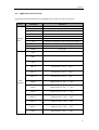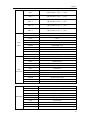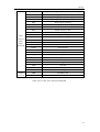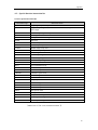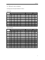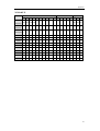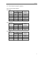
1
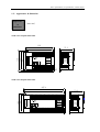
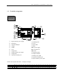
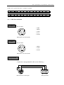
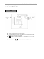
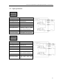
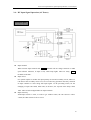
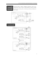
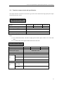
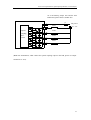
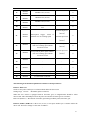
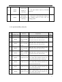
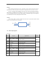
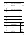
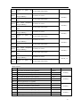
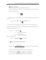
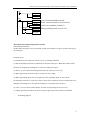
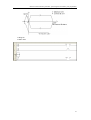
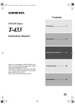
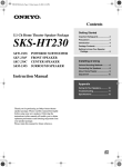
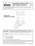
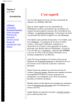
XCM motion controller User manual Xinje Electronic Co., Ltd. Data No. PC02 20080412 3.0 Xinje Electronic Catalog Foreword XCM ———————————————————— Motion control type PLC XCM User manual summarize motion controller 1 ———————————————————— The power circuit specifications, input/output specifications and 2 external wiring ———————————————————— Action and function of various register, motion control instruction 3 explanation and parameters ———————————————————— Appendix ———————————————————— The first edition 4 This manual includes some basic precautions which you should follow to keep you safe and protect the products. These precautions are underlined with warning triangles in the manual. About other manuals that we do not mention please follow basic electric operating rules. Precautions Correct Application Please follow the precautions. If not, it may lead the control system incorrect or abnormal, even cause fortune lose. The models could only be used according to the manual, and an only be used along with the peripheral equipments recognized or recommended by Xinje Electronic. They could only work normally in the condition of be transported, kept and installed correctly, also please operate and maintain them according to the recommendation. Xinje Electronic Co., Ltd. Copyright reserved Without exact paper file allowance, copy, translate or using the manual is not allowed. Disobey this, people should take the responsibility of loss. We reserve all the right of expansions and their design patent. Duty Declare We have checked the manual, its content fits the hardware and software of the products.As mistakes are unavoidable, we couldn’t promise all correct. However, we would check the data in the manual frequently, and in the next edition, we will correct the necessary information. Your recommendation would be highly appreciated 20008.06 CATALOG FOREWORD ........................................................................................................................................... 8 1.XCM MOTION CONTROLLER SUMMARIZE............................................................................ 10 1-1.INTERNAL SPECIFICATION .......................................................................................................... 21 1-2.APPEARANCE & DIMENSION ...................................................................................................... 23 1-3.TERMINAL ARRANGEMENT ........................................................................................................ 24 1-4.COM PORT DEFINITION ............................................................................................................. 25 2. POWER SPECIFICATION, I/O SPECIFICATION, EXTERNAL LAYOUT ............................... 26 2-1.POWER SPECIFICATION............................................................................................................... 27 2-2.AC POWER SUPPLY, DC INPUT ................................................................................................... 28 2-3.INPUT SPECIFICATION................................................................................................................. 29 2-4.DC INPUT SIGNAL OPERATION (AC POWER) ............................................................................. 30 2-5.TRANSISTOR OUTPUT CIRCUIT AND SPECIFICATIONS ................................................................. 32 3.MOTION CONTROL INSTRUCTION, PARAMETER, SPECIAL DATA REGISTER AND AUXILIARY RELAY ............................................................................................................................ 36 3-1.SOFT ELEMENT ID LIST .............................................................................................................. 38 3-2.MOTION CONTROL INSTRUCTION LIST (SPECIAL FOR XCM SERIES) .......................................... 40 3-3.HOW TO READ THE INSTRUCTIONS ............................................................................................. 41 3-4. OUTPUT TERMINAL ARRANGEMENT TABLE ............................................................................... 42 3-5.MOTION CONTROL INSTRUCTIONS ............................................................................................ 43 3-6.MOTION CONTROL PARAMETER ................................................................................................. 62 3-7.SPECIAL DATA REGISTER LIST .................................................................................................... 66 3-8.SPECIAL AUXILIARY RELAY LIST ................................................................................................ 67 3-9.PULSE OUTPUT SIGN BIT ............................................................................................................ 68 3-9.APPLICATION ............................................................................................................................. 74 4.APPENDIX ...................................................................................................................................... 83 4-1.BASIC ORDER CONTROL INSTRUCTION LIST ............................................................................... 85 4-2.APPLICATION INSTRUCTION LIST ............................................................................................... 87 4-3.SPECIAL FUNCTION INSTRUCTION LIST ...................................................................................... 90 4-4.HIGH SPEED COUNTER ASSIGNMENT .......................................................................................... 91 4-5.EXTERNAL INPUT INTERRUPTION ASSIGNMENT ......................................................................... 93 4-6.FREQUENCY MEASUREMENT...................................................................................................... 94 Foreword Features of XCM motion controller XCM motion controller features: The PLC integrate motion control function and ordinary PLC function in one XCM motion controller not only supports proprietary function, but also majority functions of ordinary PLC, including high speed pulse, high speed count, interruption, PID control, etc. Support at most 10-axis pulse output function XCM series contains 3/4/10-axis pulse output, meet users control demands. Predominant motion control capability It can make 2-axis linkage motion, support basic motion control instructions such as circular, linear interpolation, etc. Plane transformation Support PLAN instruction, can transform among plane X-Y, Y-Z, X-Z etc. Can expand XC series digital, analog module and BD board Similar to XC series, XCM series also support module and BD board expansion, including digital I/O, temperature control and analog module, etc. Tracking control function XCM-32T-E-3PLS has tracking control function, which is suitable for continuous processing. It can realize fixed-length and fixed-scale working. XCM serials including models: XCM-32T-E:4-axis pulse output, transistor output. XCM-32T-E-3PLS: 3-axis pulse output, transistor output. XCM-60T-E:10-axis pulse output. Supplement explanation: The instruction noted in this manual is motion control function instructions, other instructions such as sequence control, application or special function instructions, please refer to XC series PLC user manual. Notes: (1) XCM-60T-E can expand BD board, but cannot expand modules. (2) XCM-60T-E cannot support motion control instructions. Remark XCM motion controller summarize 1.XCM motion controller summarize The chapter focus on XCM series product general specifications, appearance and dimension, terminal arrangement and the definition of each communication pin. 1-1.Internal specification 1-2.Appearance and dimension 1-3.Terminal arrangement 1-4.The pin definition of communication port Power specification, I/O specification, external layout 1-1.Internal specification General Items specification Insulate voltage Specifications Above DC 500V 2MΩ Anti-noise 1000V 1uS pulse 1 minute Ambient temperature 0~60℃ Ambient humidity 5%~95% COM 1 RS-232, connect with host machine, HMI program or debug COM 2 RS-232/RS-485, connect with network or aptitude instrument、inverters etc. COM 3 Performance BD board COM port RS-232C/RS-485 Installation Can use M3 screw to fix or install directly on DIN46277 (Width 35mm) rail Ground The third type of ground (can’t ground with strong power system.) XCM performance & specification table: & Specification Item 32 points Specification 60 points Program executing format Loop scan format, timing scan format Program format Instruction, C language, ladder chart Dispose speed 0.3µs Power cut retentive Use FlashROM and Li battery User program’s capacity 128KB I/O points Interior coil’s points (M) Points Timer Input 18 points Output 14 points Input 36 points Output 24 points 8768 points 640 points 100mS timer:Set time 0.1~3276.7 seconds (T) Spec. 10mS timer:Set time 0.01~327.67 seconds 1mS timer:Set time 0.001~32.767 seconds Points Counter (C) 640 points 16 bits counter:set value K0~32767 Spec. 32 bits counter:set value K0~2147483647 Power specification, I/O specification, external layout Data Register(D) 5024 words FlashROM Register(FD) 524 words High speed dispose High speed count, pulse output, external interrupt Setting of time scan space 0~99mS Password protection 6 bits ASCII Self diagnose function Power on self-diagnose, Monitor timer, grammar checking Note: the “user program capacity 128KB” should choose password download mode. Power specification, I/O specification, external layout 1-2.Appearance & dimension Appearance & (Unit: mm) Dimension XCM series 32-point main units 139 131 COM FG COM X1 X0 73.3 X3 X2 X5 X4 X7 X6 X11 X10 X13 X12 X15 X14 X17 X16 X21 X20 110 102 94 PWR XCM-32RT-E RUN PORT1 PORT2 ERR Y 0 1 2 3 4 5 6 7 24V 0V A B COM0 Y0 COM1 Y1 COM2 Y3 Y2 Y5 Y4 Y6 Y10 COM3 Y7 TYPE:XCM-32RT-E DATE:20060410 SN:0067032266 X Xinje Electronic Co.,Ltd 0 1 2 3 4 5 6 7 COM4 Y13 Y15 Y11 Y12 Y14 3.5 XCM series 60-point main units 207.4 199.4 COM COM X0 X1 X2 X3 X4 X5 X6 X7 X10 X11 X12 X13 X14 X15 X16 73.3 X17 X20 X21 X22 X23 X24 X25 X26 X27 X30 X31 X32 X33 XCM-60RT-E RUN ERR PORT2 Y 0 1 2 3 4 5 6 7 24V 0V CAN+ A CAN- B COM0 Y0 COM1 Y1 COM2 Y2 COM3 Y3 COM4 Y4 Y5 COM5 Y6 Y7 COM6 Y10 Y11 Y12 Y13 COM7 Y14 Y15 Y16 Y17 COM8 Y20 Y21 Y22 Y23 TYPE:XCM-60RT-E DATE:20060410 SN:0067032266 PWR X PORT1 Xinje Electronic Co.,Ltd 102 94 0 1 2 3 4 5 6 7 Power specification, I/O specification, external layout 1-3.Terminal arrangement Main units 1 2 3 12 FG COM COM X0 X1 X3 X2 X4 X5 X6 X7 X10 X11 X13 X12 X14 X15 X16 X17 X20 13 14 X21 0 1 2 3 4 5 6 7 4 5 6 7 8 ① ② ③ ④ ⑤ ⑥ ⑦ ⑧ ⑨ ⑩ 19 C0 AO0 PORT2 18 AO1 VO1 AO X PWR PWR XC3-32R-E PORT1 C1 VO0 RUN AI ERR Y 0 1 2 3 4 5 6 7 0V A 24V COM0 B Y0 COM1 COM2 Y1 Y3 Y2 Y4 Y5 COM3 Y6 Y7 Y10 COM4 Y13 Y15 Y11 Y12 Y14 VI0 C0 9 AI1 C1 AI0 VI1 VI2 C2 C3 AI2 17 AI3 VI3 15 10 16 11 : input terminal, power supply : input label : expansion BD port : COM2 : COM1 : cover : output label : output terminal, 24V output : output LED : expansion module port 11: mounting hole 12: screw 13: input LED 14: LED PWR: power supply RUN: program run ERR: error 15: expansion cable 16: output terminals 17: PWR: power LED 18: expansion module port 19: input terminal, power input XCM series 60-point main units:36 Input /24 Output COM 0V 24V A COM X0 B X1 X2 COM0 X3 Y0 X4 COM1 X5 Y1 X6 COM2 X7 X10 Y2 X11 X12 COM3 Y3 Y4 X13 X14 X15 X16 X17 X20 X21 X22 X23 X24 X25 X26 X27 X30 X31 X32 X33 X34 X37 X35 X36 X40 X41 X42 X43 Y5 Y6 COM5 COM7 COM9 Y25 Y11 Y12 Y15 Y17 Y20 Y22 Y27 COM4 COM6 Y14 Y16 COM8 Y21 Y23 Y24 Y26 Y7 Y13 Y10 Power specification, I/O specification, external layout XCM series 32-point main units:18 Input /14 Output FG 0V COM A 24V COM X1 COM0 B X3 X0 Y0 X2 COM1 X5 X4 COM2 Y1 X7 X6 Y3 Y2 X11 X10 Y5 Y4 X13 X12 Y6 COM3 Y10 Y7 X15 X17 X14 X16 X21 X20 COM4 Y13 Y15 Y11 Y12 Y14 1-4.COM Port definition COM 1 Pin of COM 1: 1 2 3 4 6 5 8 7 2: PRG 4: RXD 5: TXD 6: VCC 8: GND Mini Din 8 core socket (hole) COM 2 Pin of COM 2: 1 2 3 4 6 5 7 8 4: RXD 5: TXD 8: GND Mini Din 8 core socket (hole) Program cable Connection of programmable cable as the following: 5 2 1 5 43 8 6 7 Mini Din 8core socket (pin) 1 9 6 DB 9 pin (hole) Power specification, I/O specification, external layout 2.Power specification, I/O specification, external layout This chapter focus on the power composing, internal signal circuit composing, output circuit composing and external layout method. 2-1.Power specification 2-2.AC power supply, DC input type 2-3.Input specification 2-4.DC input signal disposal (AC power supply) 2-5.Transistor output circuit and specifications Power specification, I/O specification, external layout 2-1.Power specification For the power specification of XCM motion controller basic units, please see the following table: AC power type Rated voltage AC100V~240V Voltage allowable range AC90V~265V Rated frequency 50/60Hz Allowable momentary power-cut time Interrupt time≤0.5 AC cycle,alternation≥1 s Impact current Max 40A 5mS below/AC100V max 60A 5mS below /AC200V Max power consumption 12W Power for sensor DC power type 24VDC±10% max 400mA To avoid voltage decrease, please use the power cable above 2mm2 Even power off within 10ms, PLC still can work. But if power off for long time or abnormal power voltage decreasing, PLC will stop working, output will be in OFF status, when the power on again, the PLC will auto-run. Connect the ground terminals of basic units and expansion modules together, and then ground. Rated voltage DC24V Voltage allowable range DC21.6V~26.4V Input current (Only for basic unit) 120mA DC24V Allowable momentary power-cut time 10mS DC24V Impact current 10A DC26.4V Max power consumption 12W Power for sensor 24VDC±10% Max 400mA Power specification, I/O specification, external layout 2-2.AC power supply, DC input Wiring · The power is connected between L and N terminals. 24+, COM terminals can be used as 400mA/DC24V power for sensor. Besides, this terminal can’t be given power from outside. Terminal is vacant terminal, please do not connect it or use it as relay terminal. Please connect the COM terminals of basic unit and expansion unit. Power circuit specification, input/output specification, external layout 2-3.Input specification Basic Units Model XCM-32T/XCM-60T Input signal voltage DC24V±10% Input signal current 7mA/DC24V Input ON current Above 4.5mA Input OFF current Below 1.5mA Input response time About 10ms Input signal format Contactor input or NPN open collector transistor Circuit insulation Optical-coupled insulation Input action display LED lights when input ON Expansions Model XCM-32T/XCM-48T Input signal voltage DC24V±10% Input signal current 7mA/DC24V Input ON current Above 4.5mA Input OFF current Below 1.5mA Input response time About 10ms Input signal’s format Contactor input or NPN open collector transistor Circuit insulation Optical-coupled insulation Input action display LED lights when input ON. 29 Power circuit specification, input/output specification, external layout 2-4.DC Input Signal Operation (AC Power) DC input signal Input terminal When connect input terminal and COM terminal with no-voltage contactor or NPN open collector transistor, if input is ON,LED lamp lights. There are many COM terminals in the PLC. Input circuit Use optical coupler to insulate the input primary circuit and secondary circuit, There’s a C-R filter in the secondary circuit. It is set to avoid wrong operation caused by vibration of input contactor or noise along with input signal. As the preceding reason, for the changing of input ON→OFF, OFF→ON, in the PLC, the response time delays about 10ms. There is built-in digital filter for input terminals. Input sensitivity XCM input current is 7mA, in order to get reliable action, the ON current is above 3.5mA, the OFF current is below 1.5mA. 30 Power circuit specification, input/output specification, external layout Exterior circuit for the sensors The input current of XCM is supplied by inside 24V power. If use external power to drive sensor or optical-electricity switch, the voltage should be DC 24V±4V, please use NPN open collector transistor for sensor output. Input Connection 31 Power circuit specification, input/output specification, external layout 2-5.Transistor output circuit and specifications The output terminals of XCM are all transistor type which can be divided into high-speed pulse output and normal transistor output. High-speed pulse output Model High-speed pulse output terminal XCM-32T-E XCM-32T-E-3PLS XCM-60T-E Y0~Y3 Y0~Y2 Y0~Y11 External power supply Below DC5~30V Action display LED Max current 50mA Max output frequency of the pulse 200KHz Notes: (1) For XCM-32T-E-3PLS, Y0 and X7 (high speed counter input) cannot use at the same time. (2) Y1 cannot work with expansion BD board at the same time. Normal transistor output Model Transistor output terminal External power supply Circuit insulation XCM-32T-E XCM-32T-E-3PLS XCM-60T-E Y4~Y15 Y3~Y15 Y12~Y23 Below DC5~30V Optical-coupling insulation Action display LED Maximum load 0.8A Resistance load Induce load 12W/DC24V Lamp load 1.5W/DC24V Minimum load DC5V 2mA Response time Below 0.2ms OFF→ON ON→OFF Below 0.2ms 32 Power circuit specification, input/output specification, external layout Normal transistor output circuit Output terminal The transistor output of basic unit has 1~4 common output. External power supply Please use DC5~30V power supply to drive the load. Circuit insulation Use the photo-electricity-coupling to insulate the PLC internal circuit and output transistor. Beside, each public block is separated. Action display When driving the optical-coupling, LED lights, output transistor is ON. Response time From photo-electricity coupling device driving (or cut) to transistor ON (or OFF), the time is below 0.2ms. Output current The current is 0.5A per point. But as restrict of temperature rising, the current is 0.8A every four points. Open circuit current Below 0.1mA. 33 Power circuit specification, input/output specification, external layout Y*4 Optical 光 耦 coupling 驱 drive 动 circuit 电 路 To avoid burning output unit and the PLC 为防止负载短路等故障烧坏 PCB board, please choose suitable fuse. 输出单元,烧坏可编程控制 器的基板配线,请选用合适 各负载的保险。 1A DC power DC电源 负载 Load DC5~30V Load 负载 Y*5 Load 负载 Y*6 Load 负载 Y*7 (Note: For XCM-60T-E, when connect the optical coupling output to the load, please use output terminal Y12~Y23). 34 Connect with servo driver The following is the wiring diagram of RT type PLC and servo driver. PLC Servo driver 2KΩ PUL- Y0 脉冲 Pulse PUL+ DC24V 2KΩ DIR- Y4 方向 Direction DIR+ DC24V (If external power supply is DC5V, there is no need to connect 2KΩ resistance.) 35 3.Motion control instruction, parameter, special data register and auxiliary relay The chapter introduces XCM motion control instruction function, motion control parameter, special data register and auxiliary relay. In the end of the chapter, we select two examples for reference. 3-1.Soft element ID list 3-2.Motion control instruction list 3-3.Instruction explanation reading method 3-4. Output terminal arrangement table 3-5.Motion control instruction explanation 3-6.Motion control parameter list 3-7.Special data register list 3-8.Special auxiliary relay list 3-9.Application case 36 37 3-1.Soft element ID list XCM series soft element ID is as follows. Besides, when connect input, output expansion device and special expansion device with basic units, for the input/output relay NO., please see user manual. Mark Name X Range Points 32 points 60 points 32 points 60 points Input point X000~X021(Octal ) X000~X043(Octal) 18 points 36 points Y Output point Y000~Y015(Octal) Y000~Y027(Octal) 14 points 24 points M Internal relay M0~M2999【M3000~M7999】 8000 Special use M8000~M8767 768 S0~S511 S Flow 【S512~S1023】 1024 T0~T99:100ms not accumulation T100~T199:100ms accumulation T200~T299:10ms not accumulation T Timer T300~T399:10ms accumulation 640 T400~T499:1ms not accumulation T500~T599:1ms accumulation T600~T639:1ms with interruption, precise timing C0~C299:16 bits positive/negative counter C Counter C300~C599:32 bits positive/negative counter 640 C600~C639:high speed counter D0~D2999 D Data register 【D4000~D4999】 4000 38 FlashROM register FD 1024 FD0~FD63 64 Special use FD8000~FD8349, FD8890~FD8999 460 ED0~ED36863 36864 Expansion internal register ED Special use D8000~D9023 NOTE: ※1. The area in 【 】 is the defaulted power failure retentive area. The retentive area of D, M, S, T, C can be changed. For the details, please see the following table. ※2. Flash ROM register does not have to set power failure retentive area; its data won’t lose when power is off (No battery). ※3. The address of input coil, output relay are octal data, other No. are all decimal data. ※4. The I/O which does not connect to external device can be used as internal relay. Soft element power-off retentive area settings: Name Area Function System default value Power-off retentive range D FD8202 Start denotation of D power-off retentive area 4000 D4000~D4999 M FD8203 Start denotation of M power-off retentive area 3000 M3000~M7999 T FD8204 Start denotation of T power-off retentive area 620 Not set C FD8205 Start denotation of C power-off retentive area 320 C320~C635 S FD8206 Start denotation of S power-off retentive area 512 S512~S1023 ED FD8207 Start denotation of ED power-off retentive area 0 ED0~ED36863 39 3-2.Motion control instruction list (Special for XCM series) DRV High speed positioning LIN Linear Interpolation Positioning CW Circular clockwise interpolation CCW Circular anticlockwise interpolation DRVZ Back to machine zero CHK Servo checking end DRVR Back to electrical zero SETR Electrical zero setting TIM Delay instruction ABS Absolute address INC Incremental address SETP Set coordinate system PLAN Plane selection FOLLOW Following instruction Notes: XCM-60T-E cannot support motion control instructions. 40 3-3.How to read the instructions 1 2 4 3 5 6 Notes: Instruction name 16 bits instruction and 32 bits instruction Ladder chart illustration Applicable models S· It denotes that the operand doesn't change with the instruction, called source operand. It denotes that the operand changes with the instruction, called target operand. D· 6. Successively explain the instruction's basic movement, use method, application example, expansion function, notice point, etc. 1. 2. 3. 4. 5. 41 3-4. Output terminal arrangement table There are rules for XCM output terminal function and related operation axis: XCM-32T-E Output Y0 Y1 Function Y2 Y3 Y4 Y5 Pulse output Y6 Y7 Direction output Operation axis K0 K1 K2 K3 K0 K1 K2 K3 Axis X Y Z U X Y Z U XCM-32T-E-3PLS Output Y0 Y1 Y2 Function Y3 Pulse output Y4 Y5 Direction output Operation axis K0 K1 K2 K0 K1 K2 Axis X Y Z X Y Z 42 3-5.Motion Control Instructions PLAN: select plane or space 16-bit instruction:-- 32-bit instruction:see the description below Function & Action M0 PLAN S1 S2 K0 K1 Function: select axis X and Y for operation which is XY plane. It defines the operation axis of all the following motion instructions. S1· : define the first operation axis; the following instructions will recognize this axis as the first operation axis. S2· : define the second operation axis; the following instructions will recognize this axis as the second operation axis. Notes: If do not use PLAN to define the plane, X and Y axis are default operation axis. Operation plane is X, Y. Example Instructions: LD M0 PLAN K1 K2 SETP K10000 K20000 When M0 ON, select K1 and K2 as operation axis, which is Y, Z plane. SETP can set coordinate system instruction. Change the current position register value to 10000 and 20000 for K1 and K2 axis. 43 , , plane plane plane , SETP: set coordinate system 16-bit instruction:-- 32-bit instruction: see the description below Function & action M0 SETP S1 S2 K1000 K100 Function: set the coordinate, define the plane by PLAN instruction (such as the up diagram, the new coordinate is K1000, K100). S1· Set the new coordinate of the first operation axis S2· Set the new coordinate of the second operation axis Notes: The new coordinate will instead of the old one when this instruction is executed. Besides, the value in machine zero and electric zero registers have not changed, so in fact the position of the machine zero and electric zero have changed. Example Such as the following diagram, in the original coordinate system, the current register value is (200, 200), machine zero register value is (50, 50), electric zero register value is (150, 100); after implementation of the instruction SETP K100 K100, the reference frame has changed, but the register value has not changed, at last the position has changed. 44 250 200 250 (200,200) Current value 150 200 100 150 50 Current value (100,100) (150,100) Electric zero (50,50) 100 50 (150,100) Electric zero (50,50) Machine zero (0,0) 50 100 150 200 250 Machine zero (0,0) 50 100 150 200 250 Original coordinate system Such as: current value is (200, 200) (absolute coordinates), after implementation of the instruction SETP K100 K100, the zero has changed as the following: ABS: absolute address 16-bit instruction:-- 32-bit instruction:-- Suitable type: XCM-32 Function & action After executing ABS instruction, coordinates (X, Y) will be recognized as the absolute value of zero (0, 0). 45 The displacement value of arc center (I, J) and radius (r) will be recognized as incremental value. If the address isn’t defined, it will be recognized as absolute value. Notes: ABS is corresponding to INC, once the ABS instruction is executed; it will be effective until the INC instruction is executed. Example Y 300 (100,250) 250 ABS 200 150 LIN K200 K0 100 50 ( 0,0) ( 200,0) 50 100 150 200 250 300 X After ABS instruction, the LIN instruction will do linear interpolation according to the absolute coordinates. INC: incremental address 16-bit instruction: -- 32-bit instruction: -- Suitable type XCM-32 Function & action INC After the implementation of INC instruction, address (X, Y) will be recognized as incremental value of the current position. INC instruction is similar to ABS, once INC is executed, it will be effective until ABS is 46 executed. Example INC LIN K200 K0 Y 300 ( 100,250) 250 ( 300,250) 200 150 100 50 (0,0) 50 100 150 200 250 300 X After executing INC instruction, LIN instruction will do linear interpolation according to the incremental address relatives to the current position. In the up diagram, same coordinates produce different results by using ABS and INC instructions. SETR: set electric zero 16-bit instruction:-- 32-bit instruction:-- Suitable type: XCM-32 Function & action M0 SET R 47 The current position will be stored into the electric zero register, the original zero will be replaced. Example After executing SETR instruction, the current coordinates (100, 250) will be stored into electric zero register. For actual applications, this instruction can simplify the coordinate system. Y 300 (100,250 ) 250 Electric zero 200 150 100 50 (0,0) 50 100 150 200 250 300 X DRVR: electric return to zero 16-bit instruction:-- 32-bit instruction:-- Suitable type: XCM-32 Function & action M0 DRVR The machine will return to the electric zero at high-speed and do servo end checking. The acceleration time is up to FD8910, deceleration time is up to FD8912, operation speed is up to FD8908. In actual applications, DRVR makes the coordinate system clear and simplifies the operation, decreases the error. 48 DRVZ: return to machine zero 16-bit instruction:-- Suitable type: XCM-32 32-bit instruction:-- Function & action First, we will introduce the machine zero. (1) There are two modes 1 and 2. Parameter 26 can set the mode (which is return to machine zero parameter). The bit 4 to 7 defines whether to use close-point switch. Besides, the bit 8 to 11, 12 to 15 is also related to close-point switch. (2) The other parameters related to machine zero include: (the details please refer to the appendix) Parameter 16, 17, 18, 19: set the machine zero of axis X, Y, Z, U. Parameter 20: the speed (frequency) of return to machine zero. Parameter 21: crawling speed of return to machine zero. Parameter 22, 23: corresponding to axis X, Y, zero (phase Z) pulse value whose crawling speed needs count. About mode 1 and 2: Mode1: The bit 4 to 7 of parameter 26 is 0, means do not use close-point switch. Mode2: The bit 4 to 7 of parameter 26 is 1, means use close-point switch. The bit 4 to 7 of parameter 26 is corresponding to the close-point switch of axis X, Y, Z and U. The X-axis and Y-axis support mode 1 and 2. The Z-axis and U-axis support mode1 only. The input terminals of the switch setting: Operation axis X-axis Y-axis Close-point switch setting input Z-phase zero input X2 X10 X5 X11 Z-axis U-axis — — — — Mode 1: there is no close-point switch setting. The machine decides the target position coordinates according to the parameter 16 to 19 when returning to the machine zero, and decides the direction of return to machine zero according to bit 0 to 3 of parameter 26, return speed depends on parameter 20. Mode 2: there is close-point switch setting. During the machine is returning to the machine zero, when the machine arrives the close-point switch, the speed will decrease from the value of parameter 20 (setting speed) to parameter 21 (crawling speed). The machine will stop according to the counting zero (Z-phase) pulse signal of parameter 22 and 23. Please see the following 49 diagram: X0 DRVZ Function: the machine will return to machine zero at the highest speed. PLC will select which axis to return according to the current plane, it will also decide whether to return to the machine zero according to the value of M8261~M8264 (sign bit of return to machine zero forbidden). M8265~M8268 (returning to zero sign bit of axis X, Y, Z) will be ON after returning to the zero. Two axes will return to machine zero at the same time. If need one return after another, set ON sign bit of return to machine zero forbidden. Please refer to chapter 3-5 and 3-7 for sign bits and parameters. Program example Return to the zero of axis-X, and then return to the zero of Y-axis. SET M8262 forbid the Y-axis to return to zero DRVZ the X-axis returns to machine zero RST M8262 permit the Y-axis to return to zero SET M8261 forbid the X-axis to return to zero DRVZ the Y-axis returns to machine zero RST M8261 permit the X-axis to return to zero 50 Notes: If M8261 and M8262 are all ON, DRVZ will not be executed. DRV: High Speed Positioning 16Bits Instruction: -- 32 Bits Instruction: Below Suitable Model: XCM-32 Function & Action ● S1· S2· X-axis and Y-axis high speed positioning with the maximum speed: X-axis target position; operands: K、TD、CD、D、FD. Y-axis target position; operands: K、TD、CD、D、FD. The instruction specifies the travel to the target coordinates with independent settings for the X and Y-axes. This instruction doesn’t realize interpolation function. Each axis maximum speed is specified by parameter register FD8908; acceleration/deceleration speed is determined by acceleration time parameter FD8910 and deceleration parameter FD8912. 51 Whether the position is incremental (distance from the zero point) or absolute (distance from the zero point) is specified by instruction ABS, INC. When the target position, operate speed are specified by indirect registers, the system default them as double words. Program Example Y (2000,3000) 3000 IN C 2500 2000 DRV K 1000 K 2000 1500 1000 (1000,1000) 500 (0,0) INC DRV K1000 K2000 500 1000 1500 2000 2500 3000 X Incremental Drive Method; High speed positioning with the maximum speed, the target address is: (1000,2000) LIN: Linear Interpolation Positioning 16bits instruction:-- 32bits instruction: Below Suitable Model: XCM-32 Function & Action M0 LIN S1 S2· S3 S4 k1000 k100 k0 k1000 Function: The first and second axes do linear interpolated positioning at appointed speed; the plane will be defined by PLAN. S1 First axis target position coordinates. Operand: K, TD, CD, D, FD 52 S2· S3· S4 Second axis target position coordinates. Operand: K, TD, CD, D, FD Third axis target position coordinates. Operand: K, TD, CD, D, FD (Notes: three axes motion control is not open, it is not useful to set the parameter here, but these bits must be reserved.) The speed of linear interpolated positioning. Operand: K, TD, CD, D, FD. (The highest speeds can up to 80 kHz for LIN and CW/CCW instructions) If there is no appointed speed for the first and second axes, the PLC will do linear interpolated positioning at the highest speed. M0 S D LIN S· D· k1000 k1000 The first axis target position coordinates. Operand: K, TD, CD, D, FD The second axis target position coordinates. Operand: K, TD, CD, D, FD This instruction uses two axes to move the machine to target position through beeline INC and ABS will define whether the target position is incremental or absolute value The default operation is double words when the target position and speed are appointed by registers. Program example Y (2000, 3000) 3000 2500 (1000,2000) 2000 ABS 1500 1000 LIN K1000 K2000 K0 K5000 500 ABS (0,0) 500 1000 1500 2000 2500 3000 X Absolute drive method; LIN K1000 K2000 K0 K5000 this instruction moves the machine to the target position (1000, 2000) with linear interpolated positioning at the speed of 5 KHz. 53 CW/CCW:Circular interpolation 32 digit instructions:The following 16 digit instructions-- Applicable model XCM-32 Function & Action M0 CW S1 S2 S3 S4 S5· S6 k100 k100 k100 k100 k100 k100 Function: run circular interpolation at certain speed according to the center position and target position of first and second axes. The coordinate plane will be defined by PLAN. CW is clockwise interpolation, CCW is counterclockwise interpolation. S1· S2· S3 The first axis target position coordinates, operands: K, TD, CD, D, FD. The second axis target position coordinates, operands: K, TD, CD, D, FD. Arc center position coordinates of the first axis, operands: K, TD, CD, D, FD. S4 S1· Arc center position coordinates of the second axis, operands:K, TD, CD, D, FD. S5 The third axis position, operands: K, TD, CD, D, FD. (Notes: three axes motion control is not open, so these parameters are not useful but they are reserved.) Circular peripheral speed, operands: K, TD, CD, D, FD. (The highest speed can up to 80 kHz for LIN and CW/CCW instructions) S6 If the peripheral speed is not defined, the system will default to the highest speed: M0 CW S1 S2 S3 S4 k100 k100 k100 k100 The center coordinates of first and second axes will be seemed as incremental address based on starting point. 54 Acceleration/deceleration time of the peripheral speed is set individually in FD8910 and FD8912. INC and ABS will define whether the target position is incremental or absolute value. It is default to double words operation when the target position or speed is defined by registers. If the start position and the target position is the same, the trajectory is a full circle. Program example ABS CW K1000 K500 K200 K0 K5000 Define the drive method is absolute address, move along the arc whose center incremental address is (200, 0) at the speed of 5 kHz, start from A(600,500) to B(1000,500). 55 CHK:Servo end check 16-bit instructions:-- 32-bit instructions:-- Function & Action CHK Applicable models XCM-32 Function: the machine runs servo end checking after finishing the interpolation, then runs another operation. If there is no servo end checking, the machine will run without pause when interpolating, the turning point will become smooth curve. Please note the following points when using motion control instructions: (1) If insert CHK between 2 motion control instructions, the trajectory will pause for a while when gets to appointed point, then continue running the next instruction. Otherwise, the trajectory is a smooth curve. (2) When continuous use PLAN, please add CHK before the second PLAN, otherwise the trajectory will deviate. The coil can be contained in CHK. The coil can stand for the positioning completion signal of the servo driver. The machine will pause when running CHK. The machine will run the next instruction when the coil is ON. If the coil is always ON, the function is the same as CHK without coil. If the coil is always OFF, the machine will stop and never go to the next instruction. S1 CHK S1· M100 : the coil of CHK, operand: X, Y, M, S, T, C Example 1 The machine moves from A to B to C. If inserts CHK between LIN, the trajectory is like solid line. If no CHK, the trajectory is like dotted line. 56 INC LIN K150 K200 K0 K5000 CHK LIN K50 K-150 K0 K5000 B(200,250) 250 200 150 100 50 (250,100) A (50,50) C (0,0)50 100 150 200 250 Example 2 The machine moves from A to B to C to D to E to A. Please see the solid line in the following diagram. In the program, select the XY plane at first. Select absolute drive mode, set the coordinate system to (K0, K0). At this time, select incremental drive mode in order to measure the coordinate system. After completion of the first linear interpolation instruction, run CHK M0 to cause pause which avoid smooth curve. It runs the next LIN instruction when M0 is ON. PLAN K0 K1 ABS SETP K0 K0 INC LIN K100 K0 CHK M0 LIN K0 K200 CHK M1 CW K100 K0 CHK LIN K0 K-200 CHK LIN K-200 K0 (100,200) 250 K0 K100 200 (200,200) C D B E (200,0) 150 K0 K100 K50 K0 K0 K100 K0 K100 100 50 A (0,0)50 100 150 200 250 K0 K100 57 Example(3) When there are many plane conversions in the program, select XY plane and do circular interpolations in incremental mode, then insert CHK, and select YZ plane. PLAN INC CW K0 CHK PLAN INC LIN K0 K0 K1 K0 K15000 K0 K0 D2 K1 K2 K10000 K0 D2 , Plane , Plane , Plane TIM: Delay 16-bit instruction:-- 32-bit instruction: remarks Function & Action X0 S1· Applicable models XCM-32 S1 TIM K1000 Delay time(Dwell),operands:K、TD、CD、D、FD. Use this instruction to set the waiting time between completion of one instruction and execution of another. 58 Time TIM ● Unit is 1ms, K1000 means delay 1s. ● The value of delay time is indirect set by data register. Default is double words operation. Example X0 PLAN K0 K1 K0 K0 LIN K1500 K0 K0 K1000 TIM K1000 LIN K0 K2000 K0 K1000 ABS SETP INC As the ladder chart, delay 1s after the completion of linear interpolation, then run the second linear interpolation instruction. Please see the following instructions: LD X0 PLAN K0 K1 ABS SETP K0 K0 INC LIN K1500 K0 K0 K1000 TIM LIN K0 K2000 K0 K1000 59 FOLLOW:Following instruction Applicable models XCM-32 16-bit instruction:-- Function & Action 32-bit instruction:As follows M0 FOLLOW S1· S2· S3 S4 S1· S5 S1 S2 S3 S4 C630 K10 K20 Y0 S5· Y1 : High-speed counter, it can be AB phase, single phase or direction +pulse : Operand K10 is multiplicative coefficient, operands: K, TD, CD, D, FD : Operand K20 is divided coefficient, operands: K, TD, CD, D, FD : Operand Y0 is port No. of pulse output : Operand Y1 is port NO. of pulse direction output Following instruction can output 4 or 1 time of the high-speed counter signal. The output frequency will change as the input frequency, the pulse quantity is calculated by multiply/divide coefficient. The meaning of following is: geometric magnify or minify the high-speed counter signal, then add pulse forward or backward via phase checking, finally output the pulse in the mode of pulse+direction. The output pulse quantity depends on C630. The pulse quantity is 4 times of 1-time pulse input mode when selecting 4-time pulse input mode. This instruction is used to adjust the digital control system. Control the back/forward of the operation table by manual pulse generator. It also can be applied in some cases need precise synchronization. 60 FOLLOW instruction diagram: (take Y0 as an example) Pulse input Frequency multiplication factor FD8241 High-speed counter C630 Following coefficient m/n(multiply/ divide) Feed forward compensation coefficient range (0-100%) Following fine tuning value D8502 (-100~+100) X-axis position register D8482 Position Calculation Following pulse quantity D8500 Pulse output Y0 The relationship between FOLLOW and motion control instructions: FOLLOW can be used independently without motion instructions. However, it needs to build the relationship between FOLLOW and motion control instructions when need manual pulse generator to adjust coordinates position. The pulse quantity is stored in register D8500~D8501 when running FOLLOW. At the same time, the pulse variation will be transformed into position variation of corresponding output axis, and reflect in current axis register. So FOLLOW and motion control instructions will constitute a whole unit. FOLLOW can point at X-axis, Y-axis, Z-axis, U-axis. Make sure the direction of position and encoder is consistent, the direction of FOLLOW and motion control must be consistent. Such as the above example, Y0 outputs the pulse, the direction must output from Y4. Feed forward compensation coefficient: XCM has delay from receiving to sending pulse. Modify the feed forward compensation coefficient (FD8950) to decrease the delay. The range is 0~100%. 0 means no feed forward compensation. Following fine tuning pulse quantity If the following runs for long time, it may produce the pulse accumulated error which causes the motor pulse to lead or lag. Modify D8502 can adjust the error of next pulse period. If the motor leads, set D8502 to negative, if the motor lags, set it to positive. The value in D8502 is effective in one pulse period; D8502 will be reset after the fine tuning. 61 3-6.Motion control parameter The motion control parameter can be set in special FLASH register. Each parameter and corresponding XCM register address is as following: PARA NO. Special register Name Description Default value 1 FD8892 FD8893 Pulse rate (X-axis) Pulse number per revolution 0 2 FD8894 FD8895 Pulse rate (Y-axis) Pulse number per revolution 0 3 FD8896 FD8897 Pulse rate (Z-axis) Pulse number per revolution 0 4 FD8898 FD8899 Pulse rate (U-axis) Pulse number per revolution 0 5 FD8900 FD8901 Motor resolution(X-axis) Move distance per revolution 0 6 FD8902 FD8903 Motor resolution(Y-axis) Move distance per revolution 0 7 FD8904, FD8905 Motor resolution(Z-axis) Move distance per revolution 0 8 FD8906 FD8907 Motor resolution(U-axis) Move distance per revolution 0 9 FD8908 FD8909 The highest speed Unit: Hz 0 10 FD8910 FD8911 Accelerate time Unit: ms 0 11 FD8912 FD8913 Decelerate time Unit: ms 0 12 FD8914 FD8915 Electrical zero (X-axis) 0 13 FD8916 FD8917 Electrical zero (Y-axis) 0 14 FD8918 FD8919 Electrical zero (Z-axis) 0 15 FD8920 FD8921 Electrical zero (U-axis) 0 16 FD8922 FD8923 Machine zero (X-axis) 0 62 17 FD8924 FD8925 Machine zero (Y-axis) 0 18 FD8926 FD8927 Machine zero (Z-axis) 0 19 FD8928 FD8929 Machine zero (U-axis) 0 20 FD8930 FD8931 The speed of return to machine zero 0 External input X2 21 FD8932 FD8933 Interruption trigger: return to machine zero at crawling speed (X-axis) External input X10 0 (Y-axis) 22 23 24 FD8934 FD8935 FD8936 Zero-point (Z phase) pulse number of X-axis crawling speed which need to be count Zero-point (Z phase) pulse number of Y-axis crawling speed which need to be count External input X5 (X-axis) 0 External input X11 (Y-axis) 0 - - 0 - - 0 See table (3-5-1) 0 25 FD8937 26 FD8938 27 FD8940 Magnification coefficient 28 FD8950 Feed forward coefficient Return to machine zero settings (power series of 2) 0 The following is the detailed explanation of motion control parameters: PARA.1: Pulse rate Set the X-axis pulse number per revolution which add to the driver unit Setting range: 1~65535 PLS/REV (pulse/revolution) When the servo motor is equipped with an electronic gear, its magnification should be taken into account. The relationship between the pulse rate and the electronic gear is as follows: Pulse rate (PARA.1) = Resolution of encoder (positioning feedback pulse)/electronic gear PARA.2, PARA.3, PARA.4: set the Y-axis, Z-axis, U-axis pulse number per revolution add to the driver unit. The basic settings are the same as PARA.1. 63 PARA.5: Feed rate Set the trip of the machine per rotation of the motor Setting range :1~999999(um/REV, mdeg/REV, 10-1 minch/REV) PARA.6, PAARA.7, PARA.8 set motor per rotation trip of Y-axis, Z-axis, U-axis. The basic settings are the same as PARA.1. PARA.9: Maximum speed (default speed) The machine runs as this speed if there is no appointed speed in positioning program. Other speed must be set equal to or less than this speed. Setting range: 0~200000 Hz Notes: the highest speed is 80KHz for LIN and CW/CCW instructions. PARA.10: Acceleration time Set the time of achieving the maximum speed Setting range: 0~5000ms When PARA.10 is 0, the machine actually accelerates in 1 ms. PARA.11: Deceleration time Set the time to stop the machine. Setting range: 0~5000ms When PARA.11 is 0, the machine actually decelerates in 1 ms. PARA.12: X-axis electric zero address The absolute address of DRVR instruction Setting range:-999999 to +999999 The address is an absolute value. PARA.13, PARA.14, PARA.15 set the electric zero absolute address of Y-axis, Z-axis, U-axis. The basic setting is the same as PARA.12. PARA.16: Machine zero address After the operation of DRVZ(return to zero), set the current address as the machine configuration. Setting range:-999999 to +999999 PARA.17, PARA.18, PARA.19 set the machine zero address of Y-axis, Z-axis, U-axis. The basic setting is the same as PARA. 16. PARA20: return to machine zero speed Set the speed when the machine is returning to the zero point, the set value must be equal to or less than the maximum speed of PARA.9 Setting range:10 to 50000 Hz. 64 PARA.21: crawling speed returning to the machine zero The low speed after the near-point DOG signal (external input X2 of X-axis, external input X10 of Y-axis) is turn on. Setting range: 10 to 50000 Hz PARA.22: zero point (Z phase) pulse number of crawling speed which needs to be count After near-point DOG signal is triggered, the external input X5 of X-axis and external input X11 of Y-axis receive the encoder zero-point signal. If this signal is equal to the appointed zero point pulse number, the machine will stop. Setting range: 0 to 2147483647 PARA.23: zero point (Z phase) pulse number of Y-axis crawling speed which needs to be count. The basic setting is the same as PARA.22. PARA.24, PARA.25: invalid parameters PARA.26: returning to machine zero (FD8938) (0~3 bit) the direction returning to the machine zero (4~7 bit) Whether to use proximity switch If not use proximity switch, then machine zero returning is the same as electrical zero returning, direct decelerate and stop. (8~11 bit) Proximity switch state 0: normal open 1: normal closed (12~15 bit) Proximity switch logic 0: rising edge is effective 1: falling edge is effective 0 bit 1 bit 2 bit 3 bit X-axis machine zero returning direction (0:positive 1:negative) Y-axis machine zero returning direction (0:positive 1:negative) Z-axis machine zero returning direction (0:positive 1:negative) U-axis machine zero returning direction (0:positive 1:negative) 4 bit 5 bit 6 bit 7 bit X-axis whether to use proximity switch (0: not use 1: use) Y-axis whether to use proximity switch (0: not use 1: use) Z-axis whether to use proximity switch (0: not use 1: use) U-axis whether to use proximity switch (0: not use 1: use) 65 8 bit 9 bit 10 bit 11 bit X-axis proximity switch state (0: normal open 1: normal close) Y-axis proximity switch state (0: normal open 1: normal close) Z-axis proximity switch state (0: normal open 1: normal close) U-axis proximity switch state (0: normal open 1: normal close) 12 bit 13 bit 14 bit 15 bit X-axis proximity switch logic(0: rising 1: falling) Y-axis proximity switch logic(0: rising 1: falling) Z-axis proximity switch logic(0: rising 1: falling) U-axis proximity switch logic(0: rising 1: falling) PARA.27: Amplification factor When the system operates the data, all the decimals will be ignored, the data will be stored in integer. Before the system operation, expand 2n (n: amplification factor) times for the data which can improve the calculation precision. After the calculation, divide the data by 2n. The bigger the amplification factor, the higher the calculation precision. However, if the factor is too big, the register will overflow. Generally, set the factor to 6. (Notes: normally, don’t set this parameter, to avoid calculation error). PARA.28: Feed forward compensation coefficient Range: 0%~100%. 0% means no feed forward compensation. The following instruction outputs the pulse after receiving the pulse and internal processing, so there will be delay effect. Modify the delay effect by feed forward compensation to achieve the best synchronization. 3-7.Special data register list No. Special data register Function Explanation 1 D8482 D8483 Current position (0-axis) 0-axis current coordinates position 2 D8484 D8485 Current position (1-axis) 1-axis current coordinates position 3 D8486 D8487 Current position (2-axis) 2-axis current coordinates position 4 D8488 D8489 Current position (3-axis) 3-axis current coordinates position Current segment The No. of current running motion control instruction. (Current segment only points to motion control instructions. General PLC instructions are not included in it.) 5 D8490 D8491 Default value 0 0 0 0 0 66 6 7 D8500 D8501 Current pulse number of following The pulse number output by FOLLOW instruction D8502 Fine tuning pulse number of following Increased or decreased pulse number in one scanning period. It resets after the scanning period. 3-8.Special auxiliary relay list NO. Special auxiliary relay Function Explanation Default value 1 M8260 Flow control bit See note[1] 0 M8261 Forbid X-axis return to machine zero bit When this bit is ON, the return to zero instruction of this axis will not work. M8262 Forbid Y-axis return to machine zero bit When this bit is ON, the return to zero instruction of this axis will not work. M8263 Forbid Z-axis return to machine zero bit When this bit is ON, the return to zero instruction of this axis will not work. M8264 Forbid U-axis return to machine zero bit When this bit is ON, the return to zero instruction of this axis will not work. When running DRVZ, this bit will from ON to OFF, when machine reach the zero point, this bit become ON, see Note [2]. 0 M8265 X-axis return to machine zero end bit When running DRVZ, this bit will from ON to OFF, when machine reach the zero point, this bit become ON. 0 M8266 Y-axis return to machine zero end bit When running DRVZ, this bit will from ON to OFF, when machine reach the zero point, this bit become ON. 0 M8267 Z-axis return to machine zero end bit When running DRVZ, this bit will from ON to OFF, when machine reach the zero point, this bit become ON. 0 M8268 U-axis return to machine zero end bit 2 3 4 5 6 7 8 9 0 0 0 0 67 Note[1]: When scanning the ladder chart in PLC, implement one after another. But motion control is based on process control, only when one instruction is completed, the next one will be executed. So, uses a special M register (M8260) to show the state of the last positioning instruction. When running, set ONM8260; when completed, set it OFF. The next instruction starts to run when receiving the M8260 falling edge signal. When running, set ON M8260 again; when completed, set it OFF. Repeat as this way, the program will run in order. Note[2]: When running DRVZ instruction, M8265 turns from ON to OFF. When machine reaches machine zero point, M8265 turns to ON again. run 3-9.Pulse output sign bit Bit register: Address Function Explanation M8170 Pulse output M8171 32-bit pulse overflow M8172 Direction 1 is positive direction, related direction output ON M8173 Pulse output ON when pulse output M8174 32-bit pulse overflow M8175 Direction 1 is positive direction, related direction output ON M8176 Pulse output ON when pulse output M8177 32-bit pulse overflow M8178 Direction 1 is positive direction, related direction output ON M8179 Pulse output ON when pulse output M8180 32-bit pulse overflow Pulse number ON when pulse output output output output output ON when overflow ON when overflow ON when overflow ON when overflow PULSE_1 PULSE_2 PULSE_3 PULSE_4 68 M8181 Direction 1 is positive direction, related direction output ON M8730 Pulse output ON when pulse output M8731 32-bit pulse overflow M8732 Direction 1 is positive direction, related direction output ON M8733 Pulse output ON when pulse output M8734 32-bit pulse overflow M8735 Direction 1 is positive direction, related direction output ON M8736 Pulse output ON when pulse output M8737 32-bit pulse overflow M8738 Direction 1 is positive direction, related direction output ON M8739 Pulse output ON when pulse output M8740 32-bit pulse overflow M8741 Direction 1 is positive direction, related direction output ON M8742 Pulse output ON when pulse output M8743 32-bit pulse overflow M8744 Direction 1 is positive direction, related direction output ON M8745 Pulse output ON when pulse output M8746 32-bit pulse overflow M8747 Direction M8210 pulse alarm (frequency 1 is alarm, 0 is correct change suddenly) M8211 Whether alarm M8212 pulse alarm (frequency 1 is alarm, 0 is correct change suddenly) M8213 Whether alarm M8214 pulse alarm (frequency 1 is alarm, 0 is correct change suddenly) M8215 Whether alarm M8216 pulse alarm (frequency 1 is alarm, 0 is correct change suddenly) output output output output output output ON when overflow ON when overflow ON when overflow ON when overflow ON when overflow ON when overflow PULSE_5 PULSE_6 PULSE_7 PULSE_8 PULSE_9 PULSE_10 1 is positive direction, related direction output ON to ignore the to ignore the to ignore the PULSE_1 1 is stop output when alarm PULSE_2 1 is stop output when alarm PULSE_3 1 is stop output when alarm PULSE_4 69 M8217 Whether alarm to ignore the M8750 pulse alarm (frequency 1 is alarm, 0 is correct change suddenly) M8751 Whether alarm M8752 pulse alarm (frequency 1 is alarm, 0 is correct change suddenly) M8753 Whether alarm M8754 pulse alarm (frequency 1 is alarm, 0 is correct change suddenly) M8755 Whether alarm M8756 pulse alarm (frequency 1 is alarm, 0 is correct change suddenly) M8757 Whether alarm M8758 pulse alarm (frequency 1 is alarm, 0 is correct change suddenly) M8759 Whether alarm M8760 pulse alarm (frequency 1 is alarm, 0 is correct change suddenly) M8761 Whether alarm to ignore the to ignore the to ignore the to ignore the to ignore the to ignore the 1 is stop output when alarm PULSE_5 1 is stop output when alarm PULSE_6 1 is stop output when alarm PULSE_7 1 is stop output when alarm PULSE_8 1 is stop output when alarm PULSE_9 1 is stop output when alarm PULSE_10 1 is stop output when alarm Words register: Address Function D8170 Low 16-bit accumulative pulse quantity Explanation Pulse number Latched D8171 High 16-bit accumulative pulse quantity PULSE_1 D8172 Current segment (No. n segment) D8173 Low 16-bit accumulative pulse quantity Latched D8174 High 16-bit accumulative pulse quantity PULSE_2 D8175 Current segment (No. n segment) D8176 Low 16-bit accumulative pulse quantity Latched D8177 High 16-bit accumulative pulse quantity PULSE_3 D8178 Current segment (No. n segment) D8179 Low 16-bit accumulative pulse quantity D8180 High 16-bit accumulative pulse quantity Latched PULSE_4 D8181 Current segment (No. n segment) 70 D8730 Low 16-bit accumulative pulse quantity Latched D8731 High 16-bit accumulative pulse quantity PULSE_5 D8732 Current segment (No. n segment) D8733 Low 16-bit accumulative pulse quantity Latched D8734 High 16-bit accumulative pulse quantity PULSE_6 D8735 Current segment (No. n segment) D8736 Low 16-bit accumulative pulse quantity Latched D8737 High 16-bit accumulative pulse quantity PULSE_7 D8738 Current segment (No. n segment) D8739 Low 16-bit accumulative pulse quantity Latched D8740 High 16-bit accumulative pulse quantity PULSE_8 D8741 Current segment (No. n segment) D8742 Low 16-bit accumulative pulse quantity Latched D8743 High 16-bit accumulative pulse quantity PULSE_9 D8744 Current segment (No. n segment) D8745 Low 16-bit accumulative pulse quantity Latched D8746 High 16-bit accumulative pulse quantity PULSE_10 D8747 Current segment (No. n segment) D8210 Error segment no. PULSE_1 D8212 Error segment no. PULSE_2 D8214 Error segment no. PULSE_3 D8220 Accuracy of frequency measurement The bit behind decimal point 1 means ×10, 2 means ×100 D8216 Error segment no. PULSE_4 D8750 Error segment no. PULSE_5 D8752 Error segment no. PULSE_6 D8754 Error segment no. PULSE_7 D8756 Error segment no. PULSE_8 71 D8758 Error segment no. PULSE_9 D8760 Error segment no. PULSE_10 D8190 Low 16-bit of current pulse quantity D8191 High 16-bit of current pulse quantity D8192 Low 16-bit of current pulse quantity D8193 High 16-bit of current pulse quantity D8194 Low 16-bit of current pulse quantity D8195 High 16-bit of current pulse quantity D8196 Low 16-bit of current pulse quantity D8197 High 16-bit of current pulse quantity D8770 Low 16-bit of current pulse quantity D8771 High 16-bit of current pulse quantity D8772 Low 16-bit of current pulse quantity D8773 High 16-bit of current pulse quantity D8774 Low 16-bit of current pulse quantity D8775 High 16-bit of current pulse quantity D8776 Low 16-bit of current pulse quantity D8777 High 16-bit of current pulse quantity D8778 Low 16-bit of current pulse quantity D8779 High 16-bit of current pulse quantity D8780 Low 16-bit of current pulse quantity D8781 High 16-bit of current pulse quantity D8230 Rising time of absolute/relative positioning instruction (Y0) D8231 Falling time of origin returning instruction (Y0) D8232 Rising time of absolute/relative positioning instruction (Y1) D8233 Falling time of origin returning instruction (Y1) D8234 Rising time of absolute/relative positioning instruction (Y2) D8235 Falling time of origin returning instruction (Y2) D8236 Rising time of absolute/relative positioning instruction (Y3) D8237 Falling time of origin returning instruction (Y3) D8790 Rising time of absolute/relative positioning instruction (Y4) D8791 Falling time of origin returning instruction (Y4) D8792 Rising time of absolute/relative positioning instruction (Y5) D8793 Falling time of origin returning instruction (Y5) D8794 Rising time of absolute/relative positioning instruction (Y6) D8795 Falling time of origin returning instruction (Y6) PULSE_1 PULSE_2 PULSE_3 PULSE_4 PULSE_5 PULSE_6 PULSE_7 PULSE_8 PULSE_9 PULSE_10 PULSE_1 PULSE_2 PULSE_3 PULSE_4 PULSE_5 PULSE_6 PULSE_7 72 D8796 Rising time of absolute/relative positioning instruction (Y7) D8797 Falling time of origin returning instruction (Y7) D8798 Rising time of absolute/relative positioning instruction (Y10) D8799 Falling time of origin returning instruction (Y10) D8800 Rising time of absolute/relative positioning instruction (Y11) D8801 Falling time of origin returning instruction (Y11) PULSE_8 PULSE_9 PULSE_10 73 Motion control instruction, parameter, special register and auxiliary relay explanation 3-9.Application 1. Model system XCM controls the worktable position via controlling the servo motor. Worktable Electronic device CMX/CDV Locating device XCM Servo amplifier Pf: 8192[pls/rev] Servo motor M Ball screw Reducer Encoder PB 5mm 2. Parameter settings ⑴ Servo driver parameter settings: The rated speed of servo motor is 3000[r/min], the feedback pulse of encoder is 8192 [pls/rev]. As the characteristic of servo motor, at certain rotation speed, command pulse frequency f0 is equal to the feedback pulse frequency PB, and then you will obtain the following equation: f0: Command pulse frequency (Hz) (Output from the XCM) Pf: Feedback pulse (locating feedback pulse) quantity [pls/rev] PB: The screw pitch of ball screw N0: The rotation speed of servo motor[r/min] CMX: The numerator of servo driver command pulse amplification (electronic gear) CDV: The denominator of servo driver command pulse amplification (electronic gear) When the servo motor reaches the rated rotation speed, XCM needs to output the maximum command pulse frequency, here we select 200 KHz. The result is as below: CMX N0 1 256 Pf CDV 60 f 0 125 So, set "CMX=256,CDV=125" in servo amplifier. 74 Motion control instruction, parameter, special register and auxiliary relay explanation ⑵ Pulse rate and feed rate Deduce pulse rate and feed rate according to the following steps. 1.Pulse rate means the pulse quantity of servo motor rotating a circle, it can calculate pulse rate as the following formula: A Pf 1 CMX CDV Substitute the previous value (CMX:256 CDV:125) into the formula, then you will get the pulse rate. Pulse rate: A 8192 pls / rev 1 4000 pls / rev 256 125 2.Feed rate means the motion quantity of the work piece when servo motor rotates one circle. When ball screw finishes one screw pitch PB, motor rotates N2 circles, and the transmission ratio between motor and ball screw is N1. B N1 PB Feed rate N1: N2: PB: Below is calculating process: Feed rate 1 N2 machine transmission ratio rotate circle quantity screw pitch of the ball screw 1 1 B 5mm 5mm / rev 1 1rev ⑶ Convert motion quantity to pulse quantity Machine quantity Pulse quantity = × pulse quantity of every motor rotation Motor feed rate per rotation We need the work piece to move 200mm, then convert it to pulse quantity: Pulse quantity So if the work piece moves 200mm, XCM need to output 160000 pulses. 75 Motion control instruction, parameter, special register and auxiliary relay explanation If the work piece moves at the speed of 30cm/min, then convert it to pulse frequency: Pulse quantity: So if the work piece moves at 30cm/min, XCM should output pulse frequency of 4000Hz. 3. Program explanation ▲ Axis position control operation Positioning summarize: positioning device only moves as the current motion quantity. ● Operating steps ⅰ:When positioning device receives starting command, it will move as current quantity. ⅱ:When the moving ends, sets ON Y10. ● Motion diagram Speed X axis start input turn-on Output Y10 Move distance ● Procedure 76 Motion control instruction, parameter, special register and auxiliary relay explanation X0 SET M0 RST Y10 M0 INC SETR DRV K10000 K0 M8260 SET Y10 RST M0 Set to incremental address mode Set the current location to electrical zero Position at coordinate (10000, 0) When positioning ends, sets on Y10 Y10 ▲ Position with reciprocating motion constant ● Positioning summarize XCM controls work piece moving from left to right, and controls work piece up-down moving via electromagnet. ● Operate steps (1) Only the first time work piece returns to zero via starting command. (2) The electromagnet Y0 turns on which moves down the work piece. When lower limit switch X0 turns on, clamping electromagnet Y1 turns on to clamp work piece. (3) After 1.5s, move-down electromagnet Y0 turns off, work piece moves up. (4) When upper limit switch X1 turns on, work piece moves right. (5) When positioning device arrives at right side of the worktable (2000, 0), move-down electromagnet Y0 turns on, work piece starts to move down. When lower limit switch X0 turns on, clamping electromagnet Y1 turns off, the clamp loose to put down the work piece. (6) After 1.5s, move-down electromagnet Y0 turns off, positioning device moves up. (7) When upper limit switch X1 turns on, work piece goes back to the left side of worktable. ● Running diagram 77 Motion control instruction, parameter, special register and auxiliary relay explanation ● Program Ladder chart: 78 Motion control instruction, parameter, special register and auxiliary relay explanation 79 Motion control instruction, parameter, special register and auxiliary relay explanation Instruction: LDP M0 OUT C0 K1 count the starting times LDP C0 when starting at the first time, set on process S0 SET S0 STL S0 LD S0 OUT T201 K5 LD T201 RST M10 RST M11 ABS DRVZ go back to electrical zero DRV K0 K0 fast position to (0, 0) SETR set the current position to electrical zero LDP X1 RST S0 STLE LDP M0 not start M0 at the first time 80 Motion control instruction, parameter, special register and auxiliary relay explanation RST M11 RST M10 LDP M0 OR Y11 ANI T0 LDF M8260 AND Y12 ORB ANI M11 OUT Y11 LDP X0 MCS LDI M10 SET Y12 LD M10 RST Y12 LD M8000 SET M12 MCR LD M12 OUT T0 K15 LD T0 RST M12 LDF Y12 SET M13 LD M13 OUT T1 K15 LDP SET RST LDI MCS CHK INC DRV LDF SET MCR LDP ANI ANI SET STL reset M11 and M10 when M0 turns on, move-down electromagnet Y11 turns on when move right is finished, move-down electromagnet Y11 turns on when lower limit switch X0 turns on, clamping electromagnet Y12 turns on M12 is seemed as X0 lower limit switch sign delay for 1.5 seconds and clamping electromagnet turns on after 1.5 seconds, loose the move-down electromagnet delay for 1.5 seconds, after 1.5 seconds, turn off the move-down electromagnet, it moves up T1 M11 M13 M10 X1 K2000 M8260 M10 X1 Y11 Y12 S1 S1 K0 when X1 turns on, fast position to (2000, 0) when X1 turns on again, start process S1 and fast return 81 Motion control instruction, parameter, special register and auxiliary relay explanation LD OUT LD ABS DRV LDP RST STLE S1 T200 T200 K5 K0 K0 M0 S1 82 Appendix 4.Appendix The chapter introduces the basic and applied instructions of PLC, motion control instructions and parameters of motion controller. 4-1.Basic order control instruction list 4-2.Application instruction list 4-3.Special function instruction list 4-4.High speed counter assignment 4-5.External input interruption assignment 4-6.Frequency measurement 83 Appendix 84 Appendix 4-1.Basic order control instruction list Instruction Function Usable soft element LD Initial logical operation open) contactor NO (normally LDD Directly read state from contactor X LDI Initial logical operation NC (normally closed) contactor X、Y、M、S、T、C、Dn.m、FDn.m LDDI Directly read contactor LDP Initial logical operation-Rising edge pulse LDF Initial logical operation-Falling /trailing edge pulse X、Y、M、S、T、C、Dn.m、FDn.m AND Serial connection of NO (normally open) contactors X、Y、M、S、T、C、Dn.m、FDn.m ANDD Directly read state from contactor X ANI Serial connection of NC (normally closed) contactors X、Y、M、S、T、C、Dn.m、FDn.m ANDDI Directly read contactor ANDP Serial connection of rising edge pulse ANDF Serial connection of falling/trailing edge pulse X、Y、M、S、T、C、Dn.m、FDn.m OR Parallel connection of NC (normally closed) contactors X、Y、M、S、T、C、Dn.m、FDn.m ORD Directly read state from contact X ORI Parallel connection of NC (normally closed) contactors X、Y、M、S、T、C、Dn.m、FDn.m ORDI Directly read contactor ORP Parallel connection of rising edge pulse ORF Parallel connection of falling/trailing edge pulse ANB Serial connection of multiply parallel circuits None ORB Parallel connection of multiply parallel circuits None NC(normally NC(normally NC(normally closed) closed) closed) X、Y、M、S、T、C、Dn.m、FDn.m X X、Y、M、S、T、C、Dn.m、FDn.m X X、Y、M、S、T、C、Dn.m、FDn.m X X、Y、M、S、T、C、Dn.m、FDn.m X、Y、M、S、T、C、Dn.m、FDn.m 85 Appendix OUT Final logic operation coil drive OUTD Directly output to loop SET Set a bit device permanently ON RST Reset a bit device permanently OFF PLS Rising edge pulse PLF Falling/trailing edge pulse MCS Connect the public serial contactors None MCR Clear the public serial contactors None ALT The status of the assigned device is inverted on every operation of the instruction NOP No operation or null step None END Force the current program scan to end None GROUP Start the fold of instruction group None GROUPE End the fold of instruction group None Y、M、S、T、C、Dn.m Y Y、M、S、T、C、Dn.m Y、M、S、T、C、Dn.m X、Y、M、S、T、C、Dn.m X、Y、M、S、T、C、Dn.m X、Y、M、S、T、C、Dn.m (Note: refer to《XC series instruction manual》) 86 Appendix 4-2.Application instruction list Application instruction kinds and corresponding kinds of each series showed as below: Sort Program Flow Mnemonic Function CJ Condition jump CALL Call subroutine SRET Subroutine return STL Flow start STLE Flow end SET Open the assigned flow, close the current flow ST Open the assigned flow, not close the current flow FOR Start of a FOR-NEXT loop NEXT End of a FOR-NEXT loop FEND First end LD= LD> LD< Data Compare LD activates if (S1) = (S2) LD activates if (S1) > (S2) LD activates if (S1) =< (S2) LD<> LD activates if(S1)≠(S2) LD<= LD activates if(S1)≤(S2) LD>= LD activates if(S1)≥(S2) AND= AND activates if(S1)=(S2) AND> AND activates if(S1)>(S2) AND< AND activates if(S1)<(S2) AND<> AND activates if(S1)≠(S2) AND<= AND activates if(S1)≤(S2) AND>= AND activates if(S1)≥(S2) OR= OR activates if(S1)=(S2) 87 Appendix Data Move Data Operation Data Shift OR> OR activates if(S1)>(S2) OR< OR activates if(S1)<(S2) OR<> OR activates if(S1)≠(S2) OR<= OR activates if(S1)≤(S2) OR>= OR activates if(S1)≥(S2) CMP Data compare ZCP Data zone compare MOV Move BMOV Block move FMOV Fill move FWRT Flash ROM write MSET Zone set ZRST Zone reset SWAP Exchange the high byte and low byte XCH Exchange ADD Addition SUB Subtraction MUL Multiplication DIV Division INC Increment DEC Decrement MEAN Mean WAND Word And WOR Word OR WXOR Word exclusive OR CML Compliment NEG Negative SHL Arithmetic Shift Left SHR Arithmetic Shift Right LSL Logic shift left LSR Logic shift right ROL Rotation shift left ROR Rotation shift right SFTL Bit shift left SFTR Bit shift right WSFL Word shift left WSFR Word shift right 88 Appendix Data Convert Float Point Operation Clock Operation WTD Single word integer converts to double word integer FLT 32 bits integer converts to float point FLTD 64 bits integer converts to float point INT Float point converts to binary BIN BCD converts to binary BCD Binary converts to BCD ASC Hex. converts to ASCII HEX ASCII converts to Hex DECO Coding ENCO High bit coding ENCOL Low bit coding ECMP Float compare EZCP Float Zone compare EADD Float Add ESUB Float Subtract EMUL Float Multiplication EDIV Float division ESQR Float Square Root SIN Sine COS Cosine TAN Tangent ASIN Anti-sine ACOS Anti-cosine ATAN Anti-tangent TRD Read RTC data TWR Set RTC data (Note: refer to《XC series instruction manual》) 89 Appendix 4-3.Special function instruction list Generic special instruction list Instruction sign Instruction name PLSY Single segment pulse output without accelerate/decelerate PLSR Single/multiple segment, with accelerate/decelerate, single/double direction pulse output PLSF Variable frequency pulse output PLSNEXT/PLSNT Pulse segment switch PLSMV Save pulse number into register STOP Pulse stop COLR Modbus loop read INPR Modbus input loop read COLW Modbus single loop write MCLW Modbus multiple loops write REGR Modbus register read INRR Modbus input register write REGW Modbus single register write MRGW Modbus multiple registers write SEND Free format data send RCV Free format data incept CCOLR CAN-bus loop read CCOLW CAN-bus loop write CREGR CAN-bus register read CREGW CAN-bus register write PWM Pulse width modulate FRQM Frequency measurement STR Precise timing EI Allow interruption DI Forbid interruption IRET Interruption return PID PID operation control ZRN Zero point returning DRVA Absolute positioning DRVI Relative positioning (Note: refer to《XC series instruction manual 》) 90 Appendix 4-4.High speed counter assignment XCM high speed count input distribution as follows: XCM-32T-E Incremental mode Pulse + direction mode AB phase mode C600C602 C604C606 C608C610 C612C614 C616C618 C620 C622C624 C626C628 C630 C632C634 Max frequency 80K 10K 80K 80K 4-time √ frequency Interruption √ X000 √ U X001 √ √ U A Dir B X002 X003 U XCM-32T-E-3PLS Incremental mode Pulse + direction mode AB phase mode C600C602 C604C606 C608C610 C612C614 C616C618 C620 C622C624 C626C628 C630 C632C634 Max frequency 80K 10K 10K 10K 80K 10K 4-time 80K 10K √ frequency Interruption √ X000 √ U X001 √ √ U A Dir B X002 X003 U X004 U A Dir B X005 X006 X007 U U Notes: X7 cannot work with Y0 at the same time. 91 Appendix XCM-60T-E Incremental mode Pulse + direction mode AB phase mode C600C602 C604C606 C608C610 C612C614 C616C618 C620 C622C624 C626C628 C630 C632C634 Max frequency 80K 10K 10K 10K 4-time 80K 10K 10K √ √ √ frequency Interruption √ X000 X001 √ √ U A U B X002 X003 X004 X005 X006 U A X007 X010 X011 B U A B 92 Appendix 4-5.External input interruption assignment XCM external interruption definition: XCM-32T-E: Pointer Disable interruption Input Rising interruption Falling interruption X2 I0000 I0001 M8050 X5 I0100 I0101 M8051 X10 I0200 I0201 M8052 X11 I0300 I0301 M8053 X12 I0400 I0401 M8054 X13 I0500 I0501 M8055 XCM-32T-E-3PLS: Pointer Disable interruption Input Rising interruption Falling interruption X2 I0000 I0001 M8050 X5 I0100 I0101 M8051 X10 I0200 I0201 M8052 XCM-60T-E: Pointer Disable interruption Input Rising interruption Falling interruption X2 I0000 I0001 M8050 X3 I0100 I0101 M8051 X4 I0200 I0201 M8052 X5 I0300 I0301 M8053 93 Appendix 4-6.Frequency measurement XCM frequency measurement input: Type Input XCM-32T-E X3 XCM-32T-E-3PLS X6, X7 XCM-60T-E X1 Notes: X7 and Y0 of XCM-32T-E-3PLS cannot work at the same time. 94 Xinje Electronic Co., Ltd. 4th Floor Building 7,Orignality Industry park, Liyuan Development Zone, Wuxi City, Jiangsu Province 214072 Tel: (510)85134136 Fax: (510)85111290 www.xinje.com