1
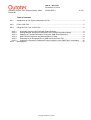
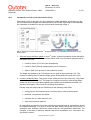
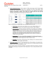
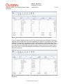
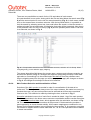
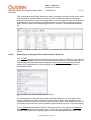
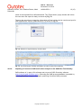
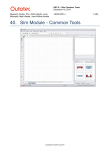
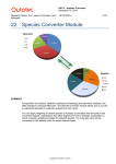
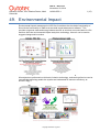
HSC 8 - Sim LCA
November 20, 2014
Research Center, Pori / Markus Reuter, Matti
Peltomäki
14022-ORC-J
1 (15)
49. Environmental Impact
Environmental impact assessment in HSC Sim 8 combines the simulation functionality of
Sim with the functionality of GaBi environmental impact assessment software1. This
provides a rigorous mass and energy balance as well as a techno-economic basis for LCA
and thus links the environmental impact analysis to technology. Hence it can be used to
suggest change and innovation.
All analyses are performed on this basis, linked to technology, and can therefore be used to
innovate the technology and/or the system and understand its resource efficiency, as
shown in Fig. 1.
Copyright © Outotec Oyj 2014
HSC 8 - Sim LCA
November 20, 2014
Research Center, Pori / Markus Reuter, Matti
Peltomäki
14022-ORC-J
2 (15)
Table of Contents
49.1.
Introduction to Life Cycle Assessment (LCA)........................................................................ 3
49.2.
LCA in HSC Sim ................................................................................................................... 5
49.3.
Using the LCA Tool in HSC Sim ........................................................................................... 6
49.3.1.
Automatic Import of All Input and Output Streams ......................................................... 6
49.3.2.
Adding Manual Streams not Defined in the Process Simulation Model .......................... 8
49.3.3.
Mapping of Process Simulation Flows with GaBi Flow Definitions ................................. 9
49.3.4.
Main Product Selection and Normalization of Data ...................................................... 10
49.3.5.
Exporting as an Ecospold File to GaBi and as an Excel File........................................ 11
49.3.6.
Importing a Process to GaBi and Further Analysis in the GaBi Plan Functionality ....... 12
49.4.
Bibliography ....................................................................................................................... 15
Copyright © Outotec Oyj 2014
HSC 8 - Sim LCA
November 20, 2014
Research Center, Pori / Markus Reuter, Matti
Peltomäki
49.1.
14022-ORC-J
3 (15)
Introduction to Life Cycle Assessment (LCA)
Calculating a LCA is defined in the ISO 14040 and 14044 standards, which belong to the
ISO environmental management standards family ISO 14000. According to the standards,
the calculation is divided into the four main phases presented in Fig. 1.
Fig. 1. Steps of Life Cycle Assessment1-4 to capture Scope 1 to 3 emissions and impacts on the
environment.
1. Goal and scope definition phase. In this 1st phase, system boundaries will be defined for
the analyzed system. System boundaries define which Unit Processes (phases) will be
included in the LCA.
Cradle to Grave (Full Life Cycle Assessment)
Cradle to Gate (Exclude transportation part to customer)
Gate to Gate (One process in the production chain)
The depth and breadth of an LCA depend on the goal of each particular LCA. The
reason for making the LCA and the target group usually define the goal of the LCA.
2. Inventory analysis phase. This phase is also called the Life Cycle Inventory (LCI) phase,
which is the 2nd phase of LCA. This phase is usually the most time-consuming phase,
where the input and output data regarding the system are studied and collected. LCI
answers the question: How much of everything flows where?
Usually input and output can be classified into the following main fields:
energy inputs, raw material inputs, ancillary inputs, other physical inputs
products, co-products, and waste
releases into air, water and soil, and
other environmental aspects.
All calculating procedures should be explicitly documented and all assumptions should
be explained carefully. It is good to check the data validity during the LCA process. A
production flow definition should be made using the real production distribution. For
example, in the case of electricity, details such as fuel combustion, mix, conversion, etc.
should be included.
Copyright © Outotec Oyj 2014
HSC 8 - Sim LCA
November 20, 2014
Research Center, Pori / Markus Reuter, Matti
Peltomäki
14022-ORC-J
4 (15)
3. Impact assessment phase. The 3rd phase of LCA is also known as Life Cycle Impact
Analysis (LCIA). LCI results allow you to calculate the LCIA of the system. LCIA
identifies and evaluates the amounts and significance of the potential environmental
impacts of the product system. LCIA answers the question: What are the resulting
impacts? Calculating is usually done using four steps, where the first two are
mandatory. Fig. 2 describes the steps with example values.
Fig. 2. Life Cycle Impacts Analysis steps and a few impact factors for CO2 Eq.
Classification (All emissions are linked to one or more impact category), for
example CH4 belongs to the Global Warming Potential (GWP) category.
Characterization (Converts reference substance of the category by multiplying
the quantities by the characterization factor, which means that the result unit is
changed to the reference unit of the category where the quantity belongs. For
example, CH4 has a factor of 25, which means that CH4 contributes 25 times
more than CO2 to the global warming potential. The most common factor
developers are the Institute of Environmental Science (CML) in Europe and
TRAICI in the United States3-4.
Normalization (Converts and possibly aggregates the indicator results across
impact categories using numerical factors based on value choices. The aim is to
understand the relative magnitude for each indicator result.)
Evaluation (Gives better understanding of the reliability of the collected indicator
results. More like a quality control step.)
4. Interpretation phase. In this 4th and final phase of the LCA procedure, the results of the
LCI or LCA or both, are summarized. The main idea here is to identify significant issues
based on the LCI and LCIA phases of LCA.
Not all of these phases are always mandatory. Sometimes sufficient information is already
assimilated by carrying out only the LCI and LCIA phases. This is usually referred to as an
LCI study.
Copyright © Outotec Oyj 2014
HSC 8 - Sim LCA
November 20, 2014
Research Center, Pori / Markus Reuter, Matti
Peltomäki
49.2.
14022-ORC-J
5 (15)
LCA in HSC Sim
The HSC Sim LCA tool covers LCA phases one and two. Subsequent phases are
performed by 3rd party LCA software. When the LCI has been completed via HSC Sim, the
process and/or flowsheet is/are exported to a separate file that can be imported into GaBi
LCA software (the file is in Ecospold format). In GaBi software, other Scope 2 and 3
processes, transportation etc. are added, as will be shown in the example below. Please
consult www.pe-international.com for more information and details about GaBi at
http://www.gabi-software.com/.
The HSC Sim LCA tool can also be used to capture, in a black box summary, how much of
a compound is released into the environment, without the use of GaBi software. However,
GaBi provides mid- and end-point analyses of the impacts of these flows, materials,
compounds etc. providing a detailed impact analysis of the flows.
HSC Sim LCA analysis is always based on a complete HSC Sim process model, where the
input and output streams represent the data for the LCIA phase. In LCA analysis, the
substances of interest are only the input and output streams to the environment. Internal
streams are not taken into account because they are not relevant when analyzing the
process as one black box. As LCA does not generally base its analysis of complete
systems on closed mass and energy balances, it is always advisable to create a detailed
process model to make the LCA results more accurate.
Copyright © Outotec Oyj 2014
HSC 8 - Sim LCA
November 20, 2014
Research Center, Pori / Markus Reuter, Matti
Peltomäki
49.3.
14022-ORC-J
6 (15)
Using the LCA Tool in HSC Sim
When the process simulation model is ready, the LCA tool is started by selecting Tools
LCA Evaluation from the main menu as shown in Fig. 3.
Fig. 3. Starting the LCA tool from the main menu, also showing a Sankey diagram for total mass flow
and some extra information required for slag chemistry to check the results.
49.3.1.
Automatic Import of All Input and Output Streams
The LCA tool creates up to five sheets, namely Input, Output, Manual Input, Manual Output,
and Indicator as shown in Fig. 4. The Input and Output Streams Info sheets contain all the
process input and output streams in HSC Sim format for the process or complete flowsheet.
In these sheets, stream detail content is available and imported directly from the simulation
model.
NOTE: No internal streams are captured through this, as only streams that can interact with
the environment and flow out from the system into the environment are used in the
assessment.
Copyright © Outotec Oyj 2014
HSC 8 - Sim LCA
November 20, 2014
Research Center, Pori / Markus Reuter, Matti
Peltomäki
14022-ORC-J
7 (15)
Fig. 4. “Input” streams info sheet extracted from flowsheet showing the laterite details.
The LCA streams sheets contain the HSC Sim stream names (as defined by the design
engineer) and amounts, which must be mapped to the GaBi LCA equivalents on the GaBi
database. The default is “No Mapping” which, unless changed, will exclude that stream
from the evaluation. Fig. 4 shows the details of the laterite input stream while Fig. 5 shows
the output and more specifically the pig iron stream. Please note that the exergy value is
also given, which is very useful additional information for analyzing technology, reactors,
plants, and systems.
Fig. 5. LCA Streams sheet for “Output,” also marking the main product relative to which every flow is
normalized.
Copyright © Outotec Oyj 2014
HSC 8 - Sim LCA
November 20, 2014
Research Center, Pori / Markus Reuter, Matti
Peltomäki
49.3.2.
14022-ORC-J
8 (15)
Adding Manual Streams not Defined in the Process Simulation Model
Sometimes, during the LCI development via HSC Simulation, some missing streams may
be identified. The best and recommended way is to add missing streams directly to the
process simulation model. This typically would include all fugitive emissions, additional
power, leakages from the system, etc. In some cases it is also appropriate to add streams
for LCA purposes only. Adding these is done via the “Manual Streams” sheet, as depicted
in Fig. 6.
For example, if general ancillary process electricity usage is not defined with its own stream
in the process simulation model, then it can be defined via the manual streams dialog
sheet. This can also be done for the output side. As shown in Fig. 6, the stream can be
added (click on “Add new input stream” button at the bottom of the window), adding a name
as well as the units and the amount for the flow that matches the data in the flowsheet as it
is being simulated.
Fig. 6. LCA Manual Streams sheet for defining additional flows that do not appear in the simulation.
The key indicator sheet offers the possibility to examine how much of the compounds are
released into the environment in the offgas or flue dust etc. This is a valuable part of the
evaluation as a transparent analysis can be made of all the compounds that flow into the
environment. Fig. 7 shows all the indicator values and adds them together once they have
been mapped as entering the environment. You can use the “*”’ wildcard (Table 1) to
capture more than a single compound, e.g. CO* will collect all CO and CO2 etc. species, as
defined in the model.
Table 1. Possible wildcard for compound definition
Wildcard
*
?
#
Description
Zero or more characters
Any single character
Any single digit (0-9)
You can type any compound in the sheet after having clicked on the Add new input stream
bar at the bottom of the window. Some defaults are given. The compound definition may
contain wildcards, as presented in Table 1. The LCA tool will automatically check if there
are double counts of elements/compounds/species. A message box informs the user of
double counting and will not add the compound to the list.
Copyright © Outotec Oyj 2014
HSC 8 - Sim LCA
November 20, 2014
Research Center, Pori / Markus Reuter, Matti
Peltomäki
14022-ORC-J
9 (15)
All the indicators which have some amount will be automatically added to the Manual
Output streams list. If these emissions are to be excluded from the LCA analysis, the
streams can be deleted manually by clicking the red cross.
Fig. 7. Key Indicator sheet, showing the entry of a new compound that has to be tracked for
environmental impact.
49.3.3.
Mapping of Process Simulation Flows with GaBi Flow Definitions
In order to perform LCA calculations, all HSC streams have to be mapped to GaBi
equivalents. All automatically included input and output streams have to be mapped but
mapping of predefined manual streams are not mandatory. Non-mapped streams are
discarded automatically. The mapping dialog is started by clicking the mapping button on
the button menu. On the left side of the dialog window, all the HSC Sim process streams
are given and the search tool for the GaBi database is on the right side. Stream mapping
and selection is done by drag-and-drop from the GaBi side to the HSC side (see Fig. 8).
The right side will be updated automatically if changes are made to that stream.
Fig. 8. Selecting a stream for mapping by drag-and-drop from the right into the LCA Equivalent box
as shown in red. Please note that here you also have to select where this stream comes from, using
the dropdown menu.
Selection of the flow group is always a very important step. The flow group defines the
nature of the stream, i.e. where it comes and where it flows to. There are specific group
types for input flows and output flows. The flow group is selected from the dropdown menu
as shown in Fig. 8.
Copyright © Outotec Oyj 2014
HSC 8 - Sim LCA
November 20, 2014
Research Center, Pori / Markus Reuter, Matti
Peltomäki
14022-ORC-J
10 (15)
There are two possibilities to search for the LCA equivalent of each stream.
A keyword search is one option, during which the hits are listed below the search word (Fig.
8) and the second option is a tree view for manual searching (Fig. 9). In both cases, double
click on the stream name to make a selection. With the keyword search, it is possible to
limit the search by selecting some tree view node before the search, so that the search is
performed under the selected node. All hits below that node will be presented. Also shown
is the pulldown menu for the LCA Group (Fig. 8) and the possible places where it can flow
to as selected, as shown in Fig. 9.
Fig. 9. LCA equivalent search from the GaBi database structure, selection of LCA Group. When
navigating away you are asked to apply mapping.
The stream description field shows the stream name, category and reference quantity, as
shown at the bottom of Fig. 9. If changes are required, simply drag and drop a new GaBi
equivalent or if something is to be omitted select Not defined from the pulldown menu.
When navigating away from the page you will be prompted to apply the changes as shown
in Fig. 9. All changes must always be saved to be effective.
49.3.4.
Main Product Selection and Normalization of Data
Selection of the Main product is needed in order for normalization of the data to be
performed. The Main product is always one of the output streams. No matter how many byproducts there are, only one main product can be selected as all flows are normalized
relative to this. This selection is made by checking the box, as shown in Fig. 5.
Normalize calculates how much of each flow is needed to obtain 1 kg of the main product.
The Normalize button in the button menu executes normalization and the results are written
in a new LCA normalized data sheet, which appears after the calculation, as shown in Fig.
10. The normalization sheet summarizes all the process LCA data and also provides a
good opportunity to check the data validity. All the same mappings are combined in one
stream and unmapped streams are not included in the summary. If, for example, more than
one stream is mapped with the same GaBi data “Air”, all Air LCA Equivalents will be added
to create one stream.
Copyright © Outotec Oyj 2014
HSC 8 - Sim LCA
November 20, 2014
Research Center, Pori / Markus Reuter, Matti
Peltomäki
14022-ORC-J
11 (15)
This normalization sheet (Fig. 10) also provides a complete overview of all the flows, which
thus provides an excellent black box summary of the complete simulation, producing a
complete and consistent mass and energy balance. As only mapped inputs and outputs are
considered and no internal flows, the black box does not reveal any proprietary process
detail, making it ideal for benchmarking processes, inclusion in environmental databases,
etc.
Fig. 10. A complete normalized data set defining as a black box the complete process, flowsheet or
system.
49.3.5.
Exporting as an Ecospold File to GaBi and as an Excel File
The To GaBi exporting menu button writes an Ecospold version 1.0 XML file. The exported
file contains metadata, which provides general process information as required by the LCA
methodology. Metadata information is entered in the Process Information window and
needs to be completed before exporting (Fig. 11). Stream details are taken from the
normalization sheet.
Fig. 11. Process Info dialog for entering process detail.
It is not mandatory to complete all process information fields but it is worth filling well in
order to export the process in a form that is best usable in GaBi. After completion of the
process information, save it by clicking. Process info can also be used without the LCA tool
to describe the process well, hence providing a good summary for use in a process design.
The To GaBi exporting button is found on the button menu, to the right of the Normalize
button. If normalization has not been done, the LCA tool will automatically ask you to
perform normalization first. Exporting opens a file search dialog where the location and
Copyright © Outotec Oyj 2014
HSC 8 - Sim LCA
November 20, 2014
Research Center, Pori / Markus Reuter, Matti
Peltomäki
14022-ORC-J
12 (15)
name of the exported file is defined/entered. The “Export done” popup window will inform
the user when the export is ready, as shown by Fig. 12.
There is also an option to export the information to Excel, which can be used as an input for
other applications, reports, publications etc. as shown in Fig. 13.
Fig. 12. Selection of export directory and file name.
Fig. 13. The Excel export of all the information for further use by other software.
49.3.6.
Importing a Process to GaBi and Further Analysis in the GaBi Plan Functionality
GaBi software is 3rd party LCA software and not part of HSC Chemistry software
(http://tutorials.gabi-software.com/)4. Extending the GaBi process database is possible by
selecting Database Import Ecospold, producing functional GaBi processes.
Copyright © Outotec Oyj 2014
HSC 8 - Sim LCA
November 20, 2014
Research Center, Pori / Markus Reuter, Matti
Peltomäki
14022-ORC-J
13 (15)
Fig. 14. Importing a new process to the GaBi database from the directory into which the XML file
was exported.
A file searching window opens for the exported HSC Sim file search, as shown in Fig. 14.
File selection first opens the process summary, where the user is also informed of the
process export path in the GaBi process tree. Fig. 14 lists all the flows and amounts and if
this summary is OK, the final import can be started by clicking the green play button. At the
end of this import, a log file popup appears in GaBi that informs the user whether the import
was successful or not. The log file can be closed without saving in GaBi.
Fig. 15. Process summary presented during import as a check before clicking on the play button to
complete the import.
The new process is available in GaBi Processes under the HSC folder. This HSC Sim
generated process can now be used in the new LCA plans together with all other GaBi
processes, functionality and an impact assessment performed as shown in Fig. 17.
Copyright © Outotec Oyj 2014
HSC 8 - Sim LCA
November 20, 2014
Research Center, Pori / Markus Reuter, Matti
Peltomäki
14022-ORC-J
14 (15)
Fig. 16. New process located in Processes folder under the HSC node.
Fig. 17. The imported process can now be linked to other GaBi processes, e.g. energy and the
calculated environmental impacts.
Copyright © Outotec Oyj 2014
HSC 8 - Sim LCA
November 20, 2014
Research Center, Pori / Markus Reuter, Matti
Peltomäki
49.4.
14022-ORC-J
15 (15)
Bibliography
1.
2.
3.
4.
5.
E. Worrell and M.A. Reuter (2014): Handbook of Recycling, Elsevier BV, Amsterdam,
595p. (ISBN 978-0-12-396459-5).
SFS-EN ISO 14044
SFS-EN ISO 14040
J. Gediga, Life-Cycle Assessment, pp. 555-562, In: E. Worrell and M.A. Reuter
(2014): Handbook of Recycling, Elsevier BV, Amsterdam, 595p.
GaBi Paper Clip tutorial, Handbook for Lifecycle Assessment, Using the GaBi
software, http://tutorials.gabi-software.com/
Copyright © Outotec Oyj 2014