1
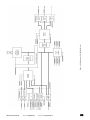
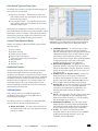
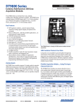
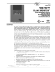
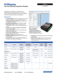
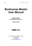
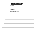
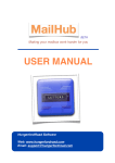
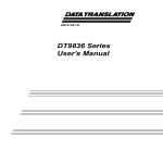
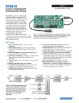
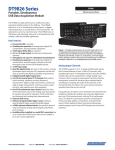
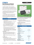
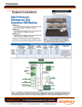
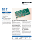
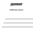
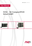
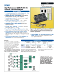
DT9862 and DT9862S DT9862 and DT9862S 10MHz High-Speed, Isolated Simultaneous USB Data Acquisition Module The DT9862 and DT9862S are high-speed, multifunction data acquisition (DAQ) modules for the USB bus. The DT9862 and DT9862S feature simultaneous analog inputs, deglitched waveform analog outputs, 32 digital input/output lines, 2 counter/timers, and 3 quadrature decoders. All subsystems can be simultaneously triggered internally or externally. The data can then be streamed synchronously to host memory. This can be done via external trigger or by the internal clock of the module. The synchronous operation allows all I/O data to be processed and correlated for all inputs and outputs. This is very valuable in determining the response across a deviceunder-test (DUT) to stimuli at the same exact instant. Key Features: ■ ■ ■ ■ ■ ■ ■ ■ ■ ■ ■ ■ ■ ■ ■ ■ ■ Throughput rate up to 10 MSamples/s The DT9862 provides a bandwidth of 10 MHz. The DT9862S provides a bandwidth of 300 MHz (typical), which allows under-sampling. Two single-ended, simultaneous analog input channels Simultaneous operation of analog input, analog output, digital I/O, and counter/timer subsystems 16-bit resolution Input range of ±2.5V (DT9862) and ±1.25V (DT9862S) 32 digital I/O lines (16 input/16 output) Two 32-bit counter/timer (C/T) channels that perform event counting, up/down counting, frequency measurement, edge-to-edge measurement, continuous edge-to-edge measurement, continuous pulse output, one-shot, and repetitive one-shot operations Three 32-bit quadrature decoders that can provide relative or absolute position of quadrature encoder input and calculate rotational speed Synchronize digital, counter, and quadrature decoder inputs with the analog measurements 0 or 2 16-bit D/A channels (depending on model selected), with output rate up to 2 MSamples/s (in small steps < 100 mV) or 500 kSamples/s per channel (simultaneous) DACs are deglitched to prevent noise from interfering with the output signal Continuous output mode or waveform generation mode External or internal clock source Trigger operations using a software command, an analog threshold value, or an external digital trigger ±500 V galvanic isolation barrier that prevents ground loops to maximize analog signal integrity and protect your computer Available installed in a 1U, 1/2 rack metal connection box with SMA connectors, or as a board-level OEM version that can be installed in a custom application www.datatranslation.com US/Canada (800) 525-8528 High-Speed USB Data Acquisition Module Figure 1. The DT9862 high-speed USB data acquisition module features SMA connectors to ensure signal integrity at maximum throughput rate of up to 10 MHz. Maximum Sampling Frequencies and Data Rates to the Host for Various Channel List Configurations Maximum Sampling Frequency Maximum Data Rate to Host Burst Sampling: 2 analog input channels 10 MHz1 28.57 MB/s1 1 analog input channel (either channel 0 or channel 1) 10 MHz 20MB/s 2 analog input channels 5 MHz2 Input Channel List Configuration 2 analog in channels + digital in + 2 counter/ timers + 3 quad decoders 0.96 MHz 28.57MB/s 3 25MB/s 1. Both channels captured in FIFO at 10 MHz. Max acquire time for 2 analog channels is 3.2768mSec. Sample rate formula: sample rate x number of channels)/1 x 65536. This is a subset of continuous acquire (the number of samples is less than or equal to the size of the input FIFO). 2. Rates as high as 7.143 MHz have been attained with an optimized system 3. Sample rate below 1 MHz can reduce accuracy. For the complete table of Maximum Sampling Frequencies and Streaming Data Rates to the Host for Various Channel List Configurations, see Appendix E in the DT9862 User’s Manual. High-Speed Analog Input Channels The DT9862 modules support two single-ended analog inputs. Each channel features its own 16-bit A/D converter, with sampling rates up to 10 MSamples/s. Using a DT9862 module, data can be acquired from a single analog input channel or from both analog input channels using the analog input channel list. Using software, specify the channels to sample. Up to 13 entries can be made in the channel list for the DT9862 and DT9862S, including the analog input channels, digital input port, two 32-bit counter/timers, and three 32-bit quadrature decoder inputs. This feature is particularly useful to correlate the timing of analog, digital, counter/timer, and quadrature decoder events. Europe/Asia +49 (0) 7142-9531–0 DT9862-2-2-OEM Board Callouts All Power Functions Synchronized ...eliminates “beat” frequencies ... minimizes subtle errors in sampling Full Simultaneous Operation and Triggering of all Functions ... analog inputs, analog outputs, DIO, C/T, Quad Decoders ±500V Galvanic Isolation Barrier Maximizes Signal Integrity ... Prevents ground loops, protects computer Synchronous Triggering & Operation for Data Streaming to Host Memory ...via external trigger or internal clock ... allows exact data correlation & response of DUT to stimuli 32 Digital I/O, 2 Counter/Timers (32-bit), 3 Quad Decoders (32-bit) Input/Output Timing and Trigger Control Input FIFO Holds 64K samples Output FIFO Holds 128K samples Board Dimensions: 7.85” (199.34mm) W 9.18” (233.17mm) L 0.85” (21.59mm) H 10 Layer PC Board ...includes 4 Layers of Ground Plane for Power and Ground to give noise-free operation Figure 2. Board Callouts 2 High-Speed Parallel 16-bit A/D Channels ... 10MHz throughput on a single channel ... 5MHz throughput on both channels operating simultaneously, ±2.5V www.datatranslation.com “Screw-on” SMA Connectors for All Analog Inputs and Outputs, Clocks, Triggers ... provides best high frequency characteristics and impedance matching US/Canada (800) 525-8528 Europe/Asia +49 (0) 7142-9531–0 2 Fast Settling, Deglitched 16-bit D/A Channels ... 2MHz (500nS) settling with small step of <100mV ... 500kHz (2uS) throughput for full scale ±2.5V 2 Figure 3. Block Diagram of the DT9862 Module www.datatranslation.com US/Canada (800) 525-8528 Europe/Asia +49 (0) 7142-9531–0 3 Input Sample Clock Sources Analog Input Conversion Modes The DT9862 series module allows the following clock sources to pace analog input operations: The DT9862 series modules support the following conversion modes: ■ ■ Internal A/D clock – Using software, specify the clock source as internal and the clock frequency at which to pace the operation. The DT9862 series modules support a minimum sampling frequency of 500 kHz, and a maximum sampling frequency of 10 MHz when sampling one analog input channel, 5 MHz when sampling two analog input channels, or 2 MHz or less when sampling other combination of input channels. External A/D clock – An external A/D clock to pace acquisitions at rates not available with the internal A/D clock. Connect an external A/D clock to the AD Clk connector on the DT9862 series module. Conversions start on the falling edge of the external A/D clock input signal. Using software, specify the clock source as external. The clock frequency is always equal to the frequency of the external A/D sample clock input signal that you connect to the module. Bandwidth of the DT9862 The DT9862 is a digitizer and provides a bandwidth of 10 MHz. It does not allow for under-sampling. For the DT9862, specify a sampling frequency that is at least twice as fast as the input’s highest frequency component (Nyquist sampling theory). For example, to accurately sample a 1 MHz signal, specify a sampling frequency of at least 2 MHz. Doing so avoids an error condition called aliasing, in which high frequency input components erroneously appear as lower frequencies after sampling. Bandwidth of the DT9862S The DT9862S is a sampler and provides a bandwidth of 300 MHz typical (100 MHz minimum), which allows undersampling. For example, if you know the approximate frequency of the signal that you are trying to acquire and the signal has a very stable frequency, you can use under-sampling to acquire many cycles of the waveform to recreate an accurate representation of the waveform. Alternatively, you can use under-sampling to isolate and remove a known high frequency component from a signal. ■ ■ Single-Value Mode Continuous Scan Mode Single-Value Mode Single value operations are the simplest to use. Using software, specify the analog input channel to sample. The module acquires the data from the specified channel and returns the data immediately. For a single-value operation, a clock source, trigger source, scan mode, or buffer cannot be specified. Single-value operations stop automatically when finished. Continuous Scan Mode Continuous scan mode takes full advantage of the capabilities of the DT9862 series module. Use continuous scan mode to accurately control the period between successive simultaneous conversions of all channels in a channel list. Specify the channel list, clock source, trigger source, scan mode, and buffer using software. When it detects an initial trigger, the module simultaneously samples all of the input channels, including the digital inputs, counter/timers, and quadrature decoders, and converts the data from the analog input channels. If the channel is included in the channel list, the sampled data is placed in the allocated buffer(s) and the operation continues until the allocated buffers are filled or the operation is stopped. The conversion rate is determined by the frequency of the input sample clock. The sample rate, which is the rate at which a single entry in the channel list is sampled, is the same as the conversion rate due to the simultaneous nature of the module. To select continuous scan mode, use software to specify the data flow as Continuous and to specify the initial trigger (the trigger source that starts the operation). The following trigger types can be selected: software trigger, an external, positive digital (TTL) trigger, an external, negative digital (TTL) trigger, or a positive analog threshold trigger as the initial trigger. Using software, a continuous scan can be stopped by performing either an orderly stop or an abrupt stop. In an orderly stop, the module finishes acquiring the current buffer, stops all subsequent acquisition, and transfers the acquired data to host memory; any subsequent triggers are ignored. In an abrupt stop, the module stops acquiring samples immediately; the current buffer is not completely filled, it is returned to the application only partially filled, and any subsequent triggers are ignored. www.datatranslation.com US/Canada (800) 525-8528 Europe/Asia +49 (0) 7142-9531–0 4 Input Triggers ■ A trigger is an event that occurs based on a specified set of conditions. Acquisition starts when the module detects the initial trigger event and stops when all the allocated buffers have been filled or when the operation is stopped. The DT9862 series modules support the following trigger sources: ■ ■ ■ Software trigger – A software trigger event occurs when you start the analog input operation (the computer issues a write to the module to begin conversions). Using software, specify the trigger source as a software trigger. External digital (TTL) trigger – An external digital (TTL) trigger event occurs when the DT9862 series module detects either a rising-edge (positive) or falling-edge (negative) transition on the signal connected to the AD Trig connector on the module. Using software, specify the trigger source as an external, positive digital (TTL) trigger or an external, negative digital (TTL) trigger. Analog threshold trigger – An analog threshold trigger event occurs when the signal on the first channel in the analog input channel list rises above a programmable threshold level. Hysteresis is fixed at 50 mV. Using software, specify the trigger source as a positive (low-tohigh transition) threshold trigger. Data Transfer Before acquisition begins, buffers must be allocated to hold the data. An event is raised whenever a buffer is filled allowing data to be moved and/or processed as needed. Data is written to multiple allocated input buffers continuously; when no more empty buffers are available, the operation stops. The data is gap-free. Output Triggers A trigger is an event that occurs based on a specified set of conditions. The DT9862 series modules support the following output trigger sources: ■ ■ The DT9862 series modules supports the following conversion modes: ■ The DT9862 series modules allows the following clock sources to pace analog output operations: Internal DAC clock – Using software, specify the clock source as internal and the clock frequency at which to pace the operation. The DT9862 series modules support a minimum sampling frequency of 0.01164 Samples/s, and a maximum sampling frequency of 2 MSamples/s (with small steps < 100 mV) or 500 kHz (full scale). www.datatranslation.com ■ Single-Value Operations are the simplest to use but offer the least flexibility and efficiency. Use software to specify the analog output channel to update, and the value to output from that channel. For a single-value operation, a clock source, trigger source, or buffer cannot be specified. Single-value operations stop automatically when finished; you cannot stop a single-value operation. Continuous analog output operations take full advantage of the capabilities of the DT9862 series module. In this mode, an output channel list, clock source, trigger source, buffer, and buffer wrap mode can be specified. Two continuous analog output modes are supported: streaming and waveform generation mode. Streaming Analog Output Output Clock Sources ■ Software trigger – A software trigger event occurs when you start the analog output operation. Using software, specify the trigger source as a software trigger. External digital (TTL) trigger – An external digital (TTL) trigger event occurs when the DT9862 series module detects a rising-edge or falling-edge transition on the signal connected to the DAC Trig connector on the module. Using software, specify the trigger source as either external, positive digital (TTL) trigger or external, negative digital (TTL) trigger. Analog Output Conversion Modes High-Speed, High-Resolution Analog Outputs The DT9862 series modules support up to two 16-bit DC-level analog output channels (depending on the DT9862 model selected). The DACs are deglitched to prevent noise from interfering with the output signal. They power up to a value of 0 V ±10 mV. The DT9862 series modules can output data to a single DAC or sequentially to both DACs and/or the digital output port. External DAC clock – An external DAC clock to pace acquisitions at rates not available with the internal A/D clock. Connect an external D/A clock to the DAC Clk connector on the DT9862 series module. Conversions start on the rising edge of the external D/A clock input signal. Using software, specify the clock source as external. The clock frequency is always equal to the frequency of the external A/D clock signal that you connect to the module. US/Canada (800) 525-8528 Use streaming analog output mode to accurately control the period between conversions of individual channels in the output channel list. Use software to fill the output buffer with the values that you want to write to the DACs and to the digital output port, if applicable. When the module detects a trigger, it starts writing the values from the output buffer to the channels specified in the output channel list. The operation repeats continuously until all the data is output from the buffers. Europe/Asia +49 (0) 7142-9531–0 5 To stop a streaming analog output operation, you can stop sending data to the module, letting the module stop when it runs out of data, or perform either an orderly stop or an abrupt stop using software. In an orderly stop, the module finishes outputting the current buffer, and then stops; all subsequent triggers are ignored. In an abrupt stop, the module stops outputting samples immediately; all subsequent triggers are ignored. Waveform Generation Use waveform generation mode if you want to output a waveform repetitively. Use software to fill the output buffer with the values that you want to write to the channels in the output channel list. For guaranteed operation with no overrun errors, use a waveform pattern that ranges from 2 to 131,072 samples (128 kSamples) if you are using one channel, 2 to 65,536 samples (64 kSamples) if you are using two channels, or 2 to 43,690 samples if you are using three channels. When it detects a trigger, the host computer transfers the entire waveform pattern to the module, and the module starts writing output values to the output channels, as determined by the output channel list. A single buffer is output repeatedly. Use software to allocate the memory and specify the waveform pattern. The DT9862 series modules allow you to program the first eight digital input lines to perform interrupt-on-change operations. Counter/Timer Channels The DT9862 series module provides two 32-bit counter/timers. Each counter accepts a clock input signal and gate input signal and outputs a pulse (pulse output signal). Using software, one or more of the counter/timers can be specified in the analog input channel list. The following clock sources are available for the counter/ timers: ■ ■ Internal C/T clock –Through software, specify the clock source as internal, and specify the frequency at which to pace the operation (this is the frequency of the Counter n Out signal). External C/T clock – An external C/T clock is useful to pace counter/timer operations at rates not available with the internal C/T clock or to pace at uneven intervals. The frequency of the external C/T clock can range up to 25 MHz. Counter/timer operations start on the rising edge of the clock input signal. Gap Free Data Gate Types Before you begin writing data to the output channels, you must allocate and fill buffers with the appropriate data. An event is returned whenever a buffer is transferred to the module. This allows you to reuse that buffer, and refill it with additional output data. In streaming mode, data is written from multiple output buffers continuously; when no more buffers of data are available, the operation stops. The data is gap-free. If the size of your buffers is less than 128 kSamples and you stop the analog output operation, the operation stops after the current buffer and the next buffer have been output. If a single buffer is used, data is written from a single output buffer continuously; when all the data in the buffer has been output, the module returns to the first location of the buffer and continues outputting the data. This process continues indefinitely until you stop it. The edge or level of the Counter n Gate signal determines when a counter/timer operation is enabled. The DT9862 series modules support the following gate types: ■ ■ ■ High-Speed Digital I/O Lines The DT9862 series module supports one digital input port, consisting of 16 digital input lines and one digital output port, consisting of 16 digital output lines. The resolution is fixed at 16 bits. You can read all 16 digital input lines or write all 16 digital output lines with a single-value digital I/O operation. In addition, you can specify the digital input port in an analog input channel list to perform a continuous digital input operation, or you can specify the digital output port in an output channel list to perform a continuous digital output operation. A digital line is high if its value is 1; a digital line is low if its value is 0. On power up or reset, a low value (0) is output from each of the digital output lines. www.datatranslation.com US/Canada (800) 525-8528 ■ ■ None – A software command enables any counter/timer operation immediately after execution. Logic-low level external gate input – Enables a counter/ timer operation when the Counter n Gate signal is low, and disables the counter/timer operation when the Counter n Gate signal is high. Note that this gate type is used for event counting and rate generation modes. Logic-high level external gate input – Enables a counter/ timer operation when the Counter n Gate signal is high, and disables a counter/timer operation when the Counter n Gate signal is low. Note that this gate type is used for event counting and rate generation modes. Falling-edge external gate input – Enables a counter/ timer operation when a high-to-low transition is detected on the Counter n Gate signal. In software, this is called a low-edge gate type. Note that this gate type is used for edge-to-edge measurement, one-shot, and repetitive one-shot mode. Rising-edge external gate input – Enables a counter/ timer operation when a low-to-high transition is detected on the Counter n Gate signal. In software, this is called a high-edge gate type. Note that this gate type is used for edge-to-edge measurement, one-shot, and repetitive one-shot mode. Europe/Asia +49 (0) 7142-9531–0 6 Pulse Output Types and Duty Cycles The DT9862 series modules can output the following types of pulses from each counter/timer: ■ ■ High-to-low transitions – The low portion of the total pulse output period is the active portion of the counter/ timer clock output signal. Low-to-high transitions – The high portion of the total pulse output period is the active portion of the counter/ timer pulse output signal. Specify the pulse output type in software. The duty cycle (or pulse width) indicates the percentage of the total pulse output period that is active. For example, a duty cycle of 50 indicates that half of the total pulse output is low and half of the total pulse output is high. Specify the duty cycle in software. Counter/Timer Operation Modes DT9862 series modules support the following counter/timer operation modes: ■ ■ ■ ■ ■ ■ ■ ■ Figure 4. quickDAQ acquires analog data from all devices supported by DT-Open Layers for .NET software at high speed, plots it during acquisition, analyzes it, and/or saves it to disk for later analysis. ■ Event counting Up/down counting Frequency measurement Edge-to-edge measurement Continuous edge-to-edge measurement Rate generation One-shot Repetitive one-shot ■ Quadrature Decoder The Quadrature Decoder module contains three quadrature decoders which allow simultaneous decoding of three quadrature encoded inputs. The quadrature decoders may be used to provide relative or absolute position or, by calculating the difference between samples, the rotational speed. Each quadrature decoder supports ʻAʼ, ʻBʼ, and ʻIndexʼ inputs. The index input may be used to zero out the positional count and the A and B input relationships are used to increment or decrement the positional count. ■ ■ Software Options Many software choices are available for application development, from ready-to-measure applications to programming environments. ■ The following software is available for use with USB modules and is provided on the Data Acquisition Omni CD: ■ DT9862 device driver – The device driver allows the use of a DT9862 module with any of the supported software packages or utilities. www.datatranslation.com US/Canada (800) 525-8528 ■ ■ quickDAQ application – An evaluation version of this .NET application is included on the Data Acquisition Omni CD. quickDAQ acquires analog data from all devices supported by DT-Open Layers for .NET software at high speed, plots it during acquisition, analyzes it, and/or saves it to disk for later analysis. Note: quickDAQ supports analog input functions only. DT9817 and DT9835 modules are DIO only and are not supported. Quick DataAcq application – The Quick DataAcq application provides a quick way to get up and running using your USB module. Using this application, verify key features of the module, display data on the screen, and save data to disk. DT-Open Layers® for .NET Class Library – Use this class library if you want to use Visual C#® or Visual Basic® for .NET to develop application software for your USB module using Visual Studio® 2003/2005/2008; the class library complies with the DT-Open Layers standard. DataAcq SDK – Use the Data Acq SDK to use Visual Studio 6.0 and Microsoft® C or C++ to develop application software for your USB module using Windows®; the DataAcq SDK complies with the DT-Open Layers standard. DTx-EZ – DTx-EZ provides ActiveX® controls, which allows access to the capabilities of your USB module using Microsoft Visual Basic or Visual C++®; DTx-EZ complies with the DT-Open Layers standard. DAQ Adaptor for MATLAB – Data Translation’s DAQ Adaptor provides an interface between the MATLAB® Data Acquisition (DAQ) toolbox from The MathWorks™ and Data Translation’s DT-Open Layers architecture. LV-Link – This software is included on the Data Acquisition Omni CD. Use LV-Link to use the LabVIEW™ graphical programming language to access the capabilities of your USB module. Europe/Asia +49 (0) 7142-9531–0 7 DT9862 acquiring data in quickDAQ Figure 5. Burst sampling allows 2 channels to acquire data at 10MHz each, and then compare results in relation to each other. For example, time periods between pulses can be measured or magnitudes compared for 2 different signals with the same triggered time frame. For burst sampling, data can be acquired for up to or less than the size of the input FIFO or 64K samples. www.datatranslation.com US/Canada (800) 525-8528 Europe/Asia +49 (0) 7142-9531–0 8 USB 2.0 Compatibility Ordering Information These modules are fully compatible with USB 2.0 and USB 1.1. USB 2.0 extends the speed of connection to up to 480 Mbps. For optimal performance, it is recommended that you use the series with a USB 2.0 port. They can be used with a USB 1.1 port, but at USB 1.1 performance. 500V Galvanic Isolation Protects Your Data Computers are susceptible to ground-spikes through any external port. These spikes can cause system crashes and may even cause permanent damage to your computer. These modules feature 500 Volts of galvanic isolation to protect your computer from ground-spikes and to ensure a reliable stream of data. EMI and ESD Design Criteria The DT9862 and DT9862S have been designed to perform with the lowest noise characteristics. Damping resistors in series with every I/O line minimize ringing and EMI and provide current limits that protect against transient signals. Flexible Packaging Configurations The DT9862 is available in two packaging configurations: a SMA connection box and an OEM embedded version. Physical dimensions in enclosure: 8.380” (212.85mm) W x 9.319” (236.7mm) L x 1.720” (43.69mm) H. Physical dimensions without enclosure (OEM): 7.848” (199.34mm) W x 9.18” (233.17mm) L x 0.85” (21.59 mm) H. The standard DT9862 module is shipped with an EP361 +5V power supply and cable. For the OEM version of the DT9862 module, you must provide your own +5 V power source or purchase the EP361 power supply and cable from Data Translation. Cross-Series Compatibility Virtually all Data Translation data acquisition modules are compatible with the DT-Open Layers for .NET Class Library. This means that if your application was developed with one of Data Translationʼs software products, you can easily upgrade to a new Data Translation board. Little or no reprogramming is needed. Documentation Each data acquisition module includes a comprehensive user’s manual. Manuals are provided in electronic (PDF) format on the Data Acquisition Omni CD provided with the module. All Data Translation hardware products are covered by a 1-year warranty. For pricing information, please visit our website or contact your local reseller. HARDWARE ■ DT9862-2-2 ■ DT9862-2-0 ■ DT9862-2-2-OEM ■ DT9862-2-0-OEM ■ DT9862S-2-0 ACCESSORIES ■ EP361 (for OEM versions) – +5V power supply and cable ■ EP379 – Dual-Rack mount kit ■ EP380 – Single-Rack mount kit ■ EP390 – 1.52-meter cable with two 78pin connectors that connect the STP78 screw terminal panel to the DT9862 ■ STP78 – Screw terminal panel for connecting digital signals to the DT9862 SOFTWARE The following software is available for purchase separately: ■ quickDAQ (SP8501-CD) – Highperformance, ready-to-run application that lets you acquire, plot, analyze, and save data to disk at up to 2 MHz per channel. FREE SOFTWARE The following software is available for free download from our website: ■ DAQ Adaptor for MATLAB – Access the analyzation and visualization tools of MATLAB®. ■ LV-Link – Access the power of Data Translation boards through LabVIEW™. Technical Support Application engineers are available during normal business hours to discuss your application requirements. Extensive product information, including drivers, example code, pinouts, a searchable Knowledge Base, and much more, is available 24 hours a day on our web site at www.datatranslation.com. You can also request complimentary support via email or fax at any time. For more information about the DT9862, please visit: http://www.datatranslation.com/info/DT9862/ Copyright © 2011 Data Translation, Inc. All rights reserved. All trademarks are the property of their respective holders. Prices, availability, and specifications are subject to change without notice. www.datatranslation.com US/Canada (800) 525-8528 Europe/Asia +49 (0) 7142-9531–0