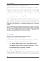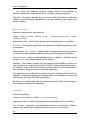
1
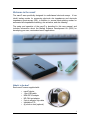
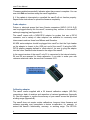
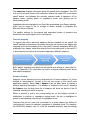
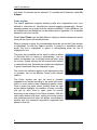
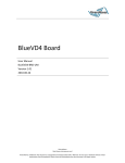
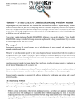
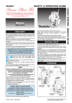
nanoZ User Manual Disclaimer Information in this document is subject to change without notice. No part of this document may be reproduced or transmitted without the express written permission of White Matter LLC. While every precaution has been taken in the preparation of this document, the publisher and the author assume no responsibility for errors or omissions, or for damages resulting from the use of information contained in this document or from the use of programs and source code that may accompany it. In no event shall the publisher and the author be liable for any loss of profit or any other commercial damage caused or alleged to have been caused directly or indirectly by this document. Distributed by Tucker Davis Technologies 11930 Research Circle Alachua, FL 32615 USA Phone: 386.462.9622 Fax: 386.462.5365 e-mail: [email protected] March 2010. © 2009-2010 White Matter LLC. All rights reserved. Table of Contents Welcome to the nanoZ.................................................................................................1 What’s in the box?......................................................................................................................................................1 Software installation.................................................................................................................................................2 Setting up the nanoZ .................................................................................................................................................2 Firmware updates......................................................................................................................................................3 Probe adaptors............................................................................................................................................................4 Calibration adaptor ...................................................................................................................................................4 nanoZ Software............................................................................................................6 Overview ........................................................................................................................................................................6 Channel mapping........................................................................................................................................................7 Adaptor window.........................................................................................................................................................7 Probe window..............................................................................................................................................................8 Report window............................................................................................................................................................9 Operating Modes .......................................................................................................11 Manual control mode.............................................................................................................................................11 Impedance test mode ............................................................................................................................................12 DC electroplate mode ............................................................................................................................................13 Impedance spectroscopy mode ........................................................................................................................14 Activation mode.......................................................................................................................................................15 Matlab Software Development Kit .............................................................................17 nanoz MEX library ..................................................................................................................................................17 Sample scripts...........................................................................................................................................................18 Function descriptions............................................................................................................................................19 getversion....................................................................................................................................................................19 enumdevs.....................................................................................................................................................................19 open ...............................................................................................................................................................................19 close ...............................................................................................................................................................................20 selectchannel .............................................................................................................................................................20 setfreq ...........................................................................................................................................................................20 startimpmetering ....................................................................................................................................................21 getimpdata .................................................................................................................................................................21 getwaveformcaps ....................................................................................................................................................22 getplatingcaps ..........................................................................................................................................................23 preparewaveform....................................................................................................................................................24 startplating ................................................................................................................................................................24 getplatingdata ..........................................................................................................................................................25 stop.................................................................................................................................................................................26 Appendix A: Principle of Operation ...........................................................................27 Appendix B: Technical Specifications.........................................................................28 Hardware....................................................................................................................................................................28 Software ......................................................................................................................................................................28 Appendix C: Channel Mapping ..................................................................................30 Adaptor definitions ................................................................................................................................................30 Electrode definitions .............................................................................................................................................31 Appendix D: NZ-‐CAL Component Values.....................................................................33 2 Year Limited Warranty ............................................................................................34 Welcome to the nanoZ The nanoZ was specifically designed for multichannel electrode arrays. It has inbuilt testing modes for measuring electrode site impedances and electrode impedance spectroscopy (EIS), in addition to several electroplating modes for automated site impedance matching, site activation, and site cleaning. The setup and operation of the nanoZ is described in this user manual, and includes information about the Matlab Software Development Kit (SDK) for developing your own, customized nanoZ applications. What’s in the box? Each nanoZ comes supplied with: o o o o o o o nanoZ device 1.8m USB cable NZA-DIP16 adaptor NZ-CAL test adaptor 3-pin to alligator clip cable Installation CD (4) stick-on feet (optional) 1 nanoZ User Manual If any item is missing or appears to be damaged or faulty, please contact the distributor from whom you purchased your nanoZ. Software installation 1. Connect your nanoZ to the computer using the USB cable provided. Let Windows search for the driver on the installation CD (in the Drivers subfolder). Follow the on-screen instructions to install the USB drivers. Note that Windows 7 may have inbuilt FTDI drivers, which are fine to use instead. 2. Run 'setup.exe' from the installation CD. Follow the on-screen instructions to install the application suite, including the optional Matlab SDK if you want to develop your own nanoZ applications under Matlab. 3. The software is ready for use. You can run the nanoZ control program from the Windows Start Menu or Desktop Shortcut. Note that if you are re-installing the software using the ʻsetup.exeʼ installer, it will overwrite any existing ʻelectrodes.iniʼ and ʻprefs.iniʼ files without warning. If you have modified these files, be sure to back them up before doing a re-installation. Setting up the nanoZ The nanoZ requires no additional hardware other than a PC with a USB port. thread mount probe connector power indicator future I/O mode indicator USB port A simple way to mount the nanoZ is with a regular laboratory retort stand or tripod and a three-prong clamp. Position the nanoZ over a small beaker of saline (or plating) solution. With this setup, it is easier to put the beaker on a heightadjustable laboratory jack and raise or lower the jack to immerse the probe in the solution, rather than adjusting the height of the nanoZ on the stand. Alternatively, remove the screw on the nanoZ adjacent to the ʻfuture I/Oʼ port, and replace with a threaded rod (3.40mm outer thread diameter) attached to a micromanipulator. This setup is ideal for in vivo applications. 2 To use the nanoZ with in vitro dish electrodes, such as MEAs from Multi Channel Systems, attach the supplied stick-on feet to the underside of the nanoZ. Place the nanoZ on a flat surface, plug the MEA adaptor into the nanoZ, and plug the MEA into the adaptor. Fill the MEA well with saline (or plating) solution. A piece of platinum wire immersed in the bath solution makes an ideal reference connection, as does a silver-silver chlorided wire or other inert metal. If the probe is connected directly to the nanoZ (e.g. a NeuroNexus A32 or A64 packaged probe), use a short jumper wire to connect one of the ʻGʼ pins on the probe PCB to the bath electrode. If using a NZA series adaptor, such as the NZA-DIP16, connect the bath electrode to the adaptor using the 3-pin-alligator cable supplied. Care should be taken to protect your setup from electromagnetic interference (EMI). The nanoZ is susceptible to EMI because it uses very small test signals for measuring impedance. To ensure accurate results, regularly check the signal quality using the Scope display of the nanoZ application. It is recommended to keep the electrode and reference connections as short as possible. Long wires may also distort results due to their capacitance. Avoid open ends which act as antennas. If necessary, wrap wire mesh or aluminum shielding around the setup, and ground the shield to the reference clip. In especially noisy environments it may also help to run the nanoZ from a battery-powered laptop. Particular care should be taken not to expose the nanoZ to liquids of any kind. If liquid gets splashed on the nanoZ, wipe it off with a moist cloth and allow to dry. If solution gets spilled inside the nanoZ, immediately unplug it and remove any attached electrodes or electrode adaptors. For water spills, allow the nanoZ to dry completely before resuming use. For saline or other solutions, remove the two screws that secure the end-cap closest to the probe connector. Slide out the printed circuit board, being careful not to damage the probe connector on the enclosure opening. Flush with distilled water to remove all traces of the spillage, and allow the circuit board to completely dry before re-assembling the nanoZ. Firmware updates Follow these instructions to update the firmware on your nanoZ: 1. Plug in the nanoZ and run the 'nanoZ' application. 2. Select Help | Update firmware from the Main Menu. 3. Click File to select the new firmware (e.g. 'nanoZ_firmware1.13x.hex'). 4. Select the nanoZ device you wish to update by serial number. If only one device is plugged in, only one serial number will appear in the drop-down list. 5. Click Update. While the new firmware is being uploaded the green LED on the nanoZ will flicker. Do not unplug the nanoZ during the upload. The message 3 nanoZ User Manual 'Firmware updated successfully' indicates when the process is complete. You can now click Exit and continue using the nanoZ application. 6. If the update is interrupted or cancelled the nanoZ will not function properly. Repeat these instructions to upload the firmware completely. Probe adaptors Probes or electrode arrays that have Samtec connectors (MOLC‐110‐01‐S‐Q) can be plugged directly into the nanoZ, assuming they conform to the nanoZʼs native pin mapping (see Appendix C). The nanoZ comes with a NZA-DIP16 adaptor for probes that use a DIP16 connector, and a variety of other adaptors are available for commonly used interconnects such as those from Millmax and Omnetics. All NZA series adaptors should be plugged into nanoZ so that the 3-pin header on the adaptor is closest to the USB port end of the nanoZ. If using the NZADIP16 adaptor mapping defined in ʻelectrodes.iniʼ, be sure to plug the adaptor into the ʻlowerʼ Samtec socket closest to the edge of the nanoZ. In the current version of the nanoZ, only R1 is connected to the internal circuitry. R2 and R3 are reserved for future expansion. If you wish to make your own reference electrode cable, be sure that it connects to R1. R1 plug adaptor into the nanoZ with this end oriented towards the USB port Calibration adaptor The nanoZ comes supplied with a 32 channel calibration adaptor (NZ-CAL) comprising a bank of resistors and capacitors of various impedances (Appendix D). Use this adaptor to confirm the accuracy of your nanoZ across the specified working range (Appendix B). The nanoZ does not require routine calibrations, however future firmware and software upgrades may necessitate a device re-calibration, for example, to extend the nanoZʼs functionality, accuracy, or working range. The NZ-CAL 4 adaptor may also be used to test whether 3rd party electrode adaptors or tether cables introduce errors in the impedance measurements. 5 nanoZ User Manual nanoZ Software Overview There are two options for interfacing with the nanoZ: a Windows-based nanoZ application, and the Matlab SDK, which runs under Matlab. Refer to the ʻMatlab software development kitʼ section of the User Manual for detailed instructions on how to control the nanoZ from Matlab. The nanoZ application can be run from the Windows Start menu or Desktop shortcut. The application will connect with the first available nanoZ device. If the nanoZ is plugged into the USB port after the application has already started, it can be selected from the Device list on the Main Menu. adaptor, electrode selection virtual DMM, scope display mode selection settings for current mode device status An intuitive graphical user interface makes the nanoZ easy to use. User-programmable electrode site configurations (see Probe window) provide a meaningful way to visualize the integrity of the electrode array, and allow subsets of channels to be tested and/or conditioned by selecting the relevant sites with a few mouse clicks. A virtual digital multimeter (DMM) displays real-time impedance measurements and the current plating voltage, depending on the mode of operation. Clicking on Scope or selecting View | Scope from the Main Menu will display a virtual oscilloscope display with the test or plating (output) waveform in green, and the measured (input) waveform in cyan. Use the arrow icons to change the horizontal (time) and vertical (amplitude) zoom. To switch back to the DMM display, click DMM or select View | DMM from the Main Menu. 6 The status bar displays information about the nanoZ device hardware. The LED icon on the left hand corner of the status bar reflects the mode LED on the actual nanoZ device, and indicates the currently selected mode of operation: off for passive mode, glowing green for impedance mode, and glowing red for electroplating mode. Impedance data are displayed in an Excel-like spreadsheet (see Report window), which can be saved to file for storage or further analysis in programs like Microsoft Excel or Matlab. The specific settings for the manual and automated modes of operation are described in the next chapter of the User Manual. Channel mapping To support the various electrode adaptors that are available for the nanoZ, the nanoZ application seamlessly translates the probe site layout to the adaptor pin mapping, and from the adaptor pins to the nanoZʼs internal multiplexer (MUX). By mapping in two stages, rather than directly from the probe layout to the nanoZ, it is unnecessary to construct a new probe mapping for different adaptors. probe site layout adaptor pin mapping nanoZ MUX channel Both adaptor mappings and electrode site layouts are defined in ʻelectrodes.iniʼ. Refer to Appendix C for information on how to configure additional probe layout and adaptor mappings. Adaptor window Adaptors can be selected from the drop-down list of known adaptors (i.e. those defined in ʻelectrodes.iniʼ) located in the left top corner of the nanoZ main application window. Select View | Adaptor from the Main Menu to display a window depicting the adaptor. If no adaptor is attached to the nanoZ, selecting No Adaptor from the drop-down list of adaptors will show the layout of the 64 channels used by the native connector. When a channel is active, the corresponding pin on the Adaptor window is highlighted. In passive or impedance testing mode, the pin is highlighted in green; in electroplating mode the pin is highlighted in red. Channels that are not used (not connected) for a given adaptor (as defined in ʻelectrodes.iniʼ) cannot be selected, regardless of operating mode. For example, the NZA-DIP16 adaptor uses 16 of the 64 available channels, and accordingly 7 nanoZ User Manual only these 16 channels can be selected. To re-enable all 64 channels, select No Adaptor. Probe window The nanoZ application supports arbitrary probe site configurations and, once defined in ʻelectrodes.iniʼ, handles the channel mapping transparently. Several example probes are provided with the default installation. Probe definitions can be modified and new definitions can be added; refer to Appendix C for a detailed description on how to do this. Select View | Probe from the Main Menu to display a window showing the probe electrode site layout with numbered sites. When a channel is active, the corresponding electrode site on the Probe window is highlighted. As with the Adaptor window, in passive or impedance testing mode, the site is highlighted in green; in electroplating mode the site is highlighted in red. The probe layout window can be used to select a subset of electrode sites for testing or electroplating. You can select and deselect one or multiple electrode sites using the mouse. Double clicking the left mouse button selects or deselects all sites. Selected site numbers are displayed in green; deselected sites are displayed in grey. The current site selection applies to all automated modes of operation, but not the Manual Control mode channel selector. The Probe window can also be used to visualize impedance test results according to the probe site layout, which is more intuitive than interpreting tabular results. Once a probe has been tested, holding down the right mouse button highlights the condition of every recording site (red for short, blue for open, green for normal, according to the settings in the Report window). With the right mouse button held down, moving the mouse pointer over individual electrode sites will display a small pop-up window with the measured impedance magnitude and phase for that site. 8 Report window When using any of the automated modes of operation, the nanoZ stores test results in an Excel-like spreadsheet. To view or hide the report window, select View | Report from the Main Menu. The upper panel of the report shows information about the currently selected probe and when it was most recently tested, user-defined criteria for flagging whether or not an electrode site is faulty, and several display options. If an electrode has been selected in the main nanoZ program, the probe name and description, extracted from the corresponding ʻelectrodes.iniʼ file, is shown. The time and date when the last impedance test or plating procedure began is also displayed. The Short and Open user input boxes are editable. An electrode is considered shorted when the measured impedance magnitude falls below the value entered in Short, and is considered open circuit when the impedance magnitude is greater than the value entered in Open. Impedances within this range are considered normal. The left-most column in the spreadsheet displays the electrode site index. The column titles show the impedance test frequency and, if applicable, the plating current that was applied. In electrode impedance spectroscopy mode there will be additional columns, two for each test frequency. The body of the spreadsheet contains the most recent site impedance measurements for all tested sites. If the Phase checkbox is checked, then both the impedance magnitude and phase are displayed. If unchecked, only the impedance magnitude is shown. For electroplating modes, the cumulative plating time is shown for each individual electrode, which may vary from site to site, for example, if impedance matching mode was run. Both pre- and post-plating impedances are stored in separate columns to the left and right of the cumulative plating time, respectively. If the Statistics checkbox is checked, then the average impedance magnitude and phase ± standard deviation of all tested sites is shown at the bottom of each column. Note that if the Condition checkbox is checked, only ʻnormalʼ sites are included in these aggregate statistics. 9 nanoZ User Manual If the Condition checkbox is checked then shorted site impedance values are highlighted in red on the spreadsheet and Probe layout window. Open sites are highlighted in blue. Normal sites are displayed in green. The report can be saved to file by clicking the icon in the main program window, or selecting File | Save Report from the Main Menu. Data are saved in tab-delimited ASCII format according to the current checkbox settings (i.e. phase information will be exported only if the Phase checkbox is checked, aggregate statistics are exported according to the Statistics checkbox, etc). 10 Operating Modes The nanoZ application has five separate modes of operation for performing a variety of different tasks. These modes can be selected by clicking a button on the left pane of nanoZ application or via the Mode menu on the Main Menu. The following instructions assume that a suitable electrode adaptor and probe configuration have been chosen, and the electrode sites of interest have been selected in the Probe window. The screenshots below were taken from Windows XP. The appearance of the user interface may vary depending on the version of Windows you are using. Manual control mode This mode provides manual control of the nanoZʼs site selection, impedance testing, and DC constant current electroplating functions. A B C Selecting Impedance (A) will continuously measure the impedance of the currently selected channel (B) at the specified Test freq (C). The impedance (in Mohms), and phase angle (in degrees) will be displayed on the DMM. If One shot is checked, a single impedance measurement will be made. To stop continuous impedance measurements, select Off (A). Selecting Current (A) mode will apply a DC constant current to the currently selected channel (B) at the level indicated adjacent to the Current level slider (C). The current can be adjusted from -12uA (electrode negative) to +12uA (electrode positive) in ~100nA steps by moving the position of the slider with the mouse or arrow keys. The voltage across the electrode site will be displayed on the DMM. The DMM has limited measurement resolution (39mV) and should be considered approximate, however the calibrated current reading adjacent to the slider is accurate to within a few nA. The DMM also indicates if the voltage is out 11 nanoZ User Manual of compliance, that is, if the voltage needed to achieve the desired current is greater than the nanoZ can generate. To stop applying the current, select Off (A). Impedance test mode This mode rapidly cycles through all (or a subset) of the channels on the selected probe, measuring the impedance of each electrode. The impedance results are tabulated in the Report window (View | Report). A B C (A) Set the impedance Test frequency to the desired value. The actual test frequency that will be used is shown in the status bar. (B) Choose the number of Test cycles. The default setting of 40 cycles is a good trade-off between accuracy and speed. Increasing the number of cycles will marginally improve the accuracy due to averaging, at the expense of a longer testing duration, whereas decreasing the number of cycles may lower accuracy due to insufficient localization of the test signal in the frequency domain. The testing time per site is displayed in the status bar. (C) Click the Test probe button to begin the test. Clicking on Test probe again or pressing ESC at any time will pause the test, and you will be given the option of continuing the test or stopping. Impedance test results in the Probe report can be saved by clicking the 12 icon. DC electroplate mode This mode cycles through all (or a subset) of the electrodes on the selected probe, applying a controlled DC constant current to each site. It has two submodes of operation: fixed plating time per channel; and match impedances mode, whereby the nanoZ will only advance to the next channel when the electrode site impedance is lowered to the specified Target impedance. The DC Electroplate mode has many possible applications, including: o plating with gold or other metals to lower electrode site impedances o deposition of conductive polymers such as PEDOT to simultaneously lower the electrode site impedance and improve the site charge capacity o electrode site cleaning o in vivo or in vitro rejuvenation of electrode sites o tissue lesioning and electrode track marking B A C D (A) Select the plating mode, either Fixed plating time, or Match impedances. (B) Set the DC plating current. The current can be adjusted from -12uA (electrode negative) to +12uA (electrode positive) in ~100nA steps by moving the position of the slider. The exact current that will be applied to the electrode is indicated adjacent to the slider. The DMM has limited measurement resolution (39mV) and should be considered approximate, however the calibrated current reading adjacent to the slider is accurate to within a few nA. (C) For a fixed plating duration per site, set the desired plating Duration. If Test Z is checked, the post-plating electrode impedance is measured. For impedance matching mode, set the desired Target impedance, test frequency, and plating Interval. The plating interval specifies how long to apply the plating current before re-testing the electrode impedance. For example, a setting of 2 will apply the specified current for two seconds, test the impedance, and alternate between these two modes every two seconds until the target impedance is achieved. The 13 nanoZ User Manual total plating time is limited by the Retries setting. Once this number of plating/Z test cycles has occurred, the nanoZ will advance to the next channel even if the target impedance has not been reached. Note that if the initial electrode impedance measurement is already less than or equal to the target impedance, no current will be applied to that electrode. (D) Click the Autoplate button to begin the electroplating sequence. Clicking on Autoplate again or pressing ESC at any time will pause the plating, and you will be given the option of skipping the current electrode (Ignore), continuing the sequence, or stopping. The (pre- and post-plating) impedance test results in the Probe report can be saved by clicking the icon. Impedance spectroscopy mode This mode cycles through all (or a subset) of electrodes on the selected probe, measuring the impedance of each electrode at multiple test frequencies. A B C (A) Select the impedance Test Frequencies (in Hz) from the check-box list, or check All to test at all frequencies in the list. Click the icon to edit the list of test frequencies. Valid frequencies range between 1Hz and 4986Hz. The nanoZ will generate test sinusoidal waveforms as close as possible to the specified test frequencies. The exact test frequencies used will be displayed in the status bar and in the column titles of the Probe report. (B) Choose the number of Test cycles. The default setting of 40 cycles is a good trade-off between accuracy and speed. Increasing the number of cycles will marginally improve the accuracy due to averaging, at the expense of a longer testing duration, whereas decreasing the number of cycles may lower accuracy 14 due to insufficient localization of the test signal in the frequency domain. The total testing time per site is displayed in the status bar. (C) Click the Test probe button to begin the test. Clicking on Test probe again or pressing ESC at any time will pause the test, and you will be given the option of continuing the test or stopping. The impedance spectroscopy results in the Probe report can be saved by clicking the icon. Activation mode This mode uses cyclic voltammetry to increase the charge capacity of all (or a subset of) electrodes on the selected probe for either a fixed duration, or to match a target electrode charge capacity. Activation mode applies a bipolar, constant current square-wave to the electrode, which both lowers the impedance and increases the charge capacity, two properties that are desirable for effective electrical stimulation. With suitable electrodes and appropriate waveform settings, the activation mode can also be used for in vivo or in vitro microstimulation. A C B D (A) Only the Fixed activation time is implemented in the current software version, so this setting is currently ignored. (B) Set the Activating current. Both current settings can be adjusted from -12uA (electrode negative) to +12uA (electrode positive) in ~100nA steps, by moving the position of the sliders. The exact currents that will be applied to the electrode are indicated above the sliders. The DMM has limited measurement resolution (39mV) and should be considered approximate, however the calibrated current readings adjacent to the sliders are accurate to within a few nA. 15 nanoZ User Manual (C) Set the desired activation frequency, the Duty cycle, and the activation Duration per electrode. The Duty cycle determines the relative time of the two current phases, where the percentage refers to the first current setting in (B). If Test Z is checked, the post-plating electrode impedance is measured (at the test frequency specified). (D) Click the Activate probe button to begin the activation sequence. To illustrate a typical activation sequence, using the settings shown above as an example (i.e. 1Hz activation frequency, 25% duty cycle, currents -5uA to +2uA, and duration 30s), the nanoZ will apply 30 activation (square wave) cycles comprising a ~5uA electrode-negative current for 250ms immediately followed by a ~2uA electrode-positive current for 750ms. The post-plating site impedance will then be measured and the nanoZ will advance to the next selected electrode site. Clicking on Activate probe again or pressing ESC at any time will pause the activation, and you will be given the option of skipping the current electrode (Ignore), continuing, or stopping. The (pre- and post-activation) impedance test results in the Probe report can be saved by clicking the icon. 16 Matlab Software Development Kit The nanoZ Matlab SDK allows users to program customized nanoZ applications that are not supported by the bundled Windows program. To use the Matlab SDK you should have a licensed copy of Matlab installed on the host PC (version 2006a or later) and have the nanoZ SDK installed (refer to the Software Installation section of this User Manual). nanoz MEX library MATLAB applications can access the nanoZ through the ʻnanozʼ MEX files. Two versions are provided, one each for 32- and 64-bit versions of Matlab running under Windows (ʻnanoz.mexw32ʼ and ʻnanoz.mexw64ʼ, respectively). A MEX file can contain only one Matlab function, and because the nanoZ SDK provides multiple functions, the actual function names are passed as the first argument when calling the ʻnanozʼ gateway function. The following syntax is used for all function calls: [<output>] = nanoz('function name', arg1, arg2, ... argN); The function name is not case sensitive and can be one of the following: Name Purpose getversion Returns the version of the nanoz MEX file enumdevs Enumerates attached nanoZ devices open Opens a free nanoZ device for access by other functions close Closes an opened nanoZ device, releases system resources selectchannel Selects a channel setfreq Sets the test frequency for impedance measurements startimpmetering Starts impedance measurement getimpdata Retrieves impedance measurement data getwaveformcaps Returns information about the waveform generation capabilities getplatingcaps Returns information about the electroplating capabilities 17 nanoZ User Manual preparewaveform Prepares a waveform for use during electroplating startplating Starts electroplating getplatingdata Retrieves electroplating voltage feedback data stop Stops impedance metering or electroplating Sample scripts The following demonstration Matlab scripts are provided: o get_info.m: display hardware information about all attached nanoZ devices o measure_impedance.m: measure the impedance of a single electrode o electroplating.m: electroplating with a DC constant current They can be found in the Matlab SDK folder, accessible from the short-cut in the Windows Start Menu. These sample scripts, along with the supporting functions they use, should provide a foundation for building you own customized nanoZ applications. 18 Function descriptions getversion Returns the version of the nanoz MEX file. Usage: [major_version, minor_version] = nanoz(‘getversion’); Arguments: none. Return values: major_version, minor_version – major and minor versions of the currently installed nanoz MEX file, respectively. enumdevs Enumerates attached nanoZ devices. Usage: devs = nanoz(‘enumdevs’); Arguments: none. Return value: devs – cell array of strings, one string per each attached device, containing the device-specific serial numbers. Remarks: If a device is attached but already opened by this MEX file, or another application, it will not be enumerated. An empty cell array is returned if no devices are attached or available. open Opens and allocates a free nanoZ device for access by other functions. Usage: handle = nanoz(‘open’, serial_number); Arguments: serial_number – string, device serial number, which can be obtained using the enumdevs function. Return value: handle – number, handle to the opened device to be used to access all other device functions. Remarks: If a nanoZ device with a given serial number is not attached, or is already opened by this MEX file or another application, this function will fail. 19 nanoZ User Manual close Closes an opened nanoZ device and releases system resources. Usage: nanoz(‘close’, handle); Arguments: handle – handle to an opened device returned by the open function. Return values: none. Remarks: User Matlab programs must close the device after they have finished using it, to release system resources and allow other programs access. If a program fails to close the device, it will stay open until Matlab finishes or until the nanoz MEX file is unloaded. To unload the MEX file, issue the Matlab command ‘clear nanoz’, which will unload the MEX file, closing all open nanoZ devices. selectchannel Selects a channel to perform impedance measurement or electroplating on. Usage: nanoz(‘selectchannel’, handle, channel); Arguments: handle - handle of an opened device returned by the open function; channel – channel number to select, from 1 to 64, or 0 to de-select all channels. Return values: none. Remarks: This function connects the measurement circuit to a specific channel. Prior to switching channels any impedance measurement or electroplating that was in progress is automatically stopped. Channel switching may cause a transition on the measurement circuit that lasts about 0.5 seconds. To preserve accuracy impedance measurement is not recommended during this period. After switching channels, the circuit is put into passive mode, not applying any voltage or current to the target electrode. setfreq Sets the test frequency used for impedance measurement. Usage: [freq_achieved, fs] = nanoz(‘setfreq’, handle, freq_desired); Arguments: handle – handle to an opened device returned by the open function; freq_desired – The desired test frequency, in Hz. 20 Return values: freq_achieved – The frequency, in Hz, which can be generated by the device, as close as possible to the desired frequency, and on which the actual measurement will be performed. fs – optional return value. It receives the sampling frequency used for signal measurement. Remarks: This function prepares the device for impedance measurement. During measurements, the nanoZ applies a sinusoidal current on the target electrode and records the voltage across at the sampling frequency returned by the fs output argument. startimpmetering Starts impedance measurement. Usage: nanoz('startimpmetering’, handle, nsam_measure, numdsps); Arguments: handle – handle to an opened device returned by the open function; nsam_measure – number of samples to measure per single impedance reading; numdsps – number of overlapping impedance measurements. Return values: none. Remarks: Calling this function initiates the impedance measurement process, applying sinusoidal test current to the target electrode and measuring the voltage across it. After a given number of samples is collected (which is specified by the nsam_measure argument), the data are converted to a single, average impedance reading. Because it may take considerable time, typically about a second, to collect data for result conversion, it is possible to perform multiple concurrent conversions, partially overlapping in time with each other. This allows more impedance readings per second. The multiplication factor is specified as the numdsps parameter. For example, if one measurement lasts one second, and numdsps parameter is set to 4, there will be 4 impedance readings per second. While measuring impedance, the user program has to poll the results by calling the getimpdata function every ~30ms, or a data buffer overrun may occur. Prior to measuring impedance, a channel must be selected and a working frequency must be specified by calling the selectchannel and setfreq functions, respectively. getimpdata Retrieves impedance measurement data. 21 nanoZ User Manual Usage: [signal_samples, Z] = nanoz(‘getimpdata’, handle); Arguments: handle – handle to an opened device returned by the open function. Return values: signal_samples – vector of integers which are raw analog signal readings from the target electrode. The user application may use these readings in order to monitor, for example, the noise and interference levels during impedance measurement. If the signal is not clean, the impedance reading may be inaccurate. Z – vector of complex impedance readings, in Ohms. Remarks: During impedance measurement, the user program must call this function approximately every 30ms to poll for incoming data. Output vectors are sized according to the amount of new data that were collected between two successive calls of this function. If no data were acquired, the vectors will be empty. In typical situations, the Z vector is empty most of the time, but occasionally it has one element – the impedance reading that was most recently acquired. Failure to call this function at regular intervals may result in a buffer overrun error. Recovery from a buffer overrun requires impedance measurement to be stopped. This will cause any pending results to be lost. Note that if a buffer overrun error does occur, the impedance measurement test waveform is still applied to the currently selected channel until the ʻstopʼ function is called. getwaveformcaps Returns information about waveform generation capabilities. Usage: caps = nanoz(‘getwaveformcaps’, handle); Arguments: handle – handle to an opened device returned by the open function. Return value: caps – a Matlab structure with the following fields: fs_gen: generator sampling frequency, in Hz. Typical value is 83333Hz. fs_adc: Sampling frequency of the A/D converter. Typical value is 10417Hz. maxsam: Maximum length of the waveform, in samples. interpol: List of supported interpolation factors. Remarks: The nanoZ generates waveforms for impedance measurement and electroplating with an 8-bit digital to analog converter clocked at a sampling frequency of 83333Hz. Since this may change in future firmware upgrades, user 22 applications should not rely on the values quoted in the specifications, but rather query the attached device for its actual capabilities (fs_gen parameter). Sampling of the analog signal on the electrode is a fraction of the generator sampling frequency, in this case 1/4, which also may be changed in the future. The user program should rely on the fs_adc parameter of the caps structure. Waveforms must be uploaded into the memory of the nanoZ's microcontroller. The current version has memory for waveforms up to 126 samples (bytes) long. The minimum frequency that can be generated with a sampling frequency of 83333Hz and 126 samples is approximately 661Hz. Waveform interpolation is used to generate lower frequencies. The interpol field of the caps structure lists supported interpolation factors. Linear interpolation is used for factors of 8 or less. 16x and higher interpolation is performed by 8x linear interpolation combined with 2x or higher ratio hold interpolation, which effectively reduces the generator sample rate. Using the maximum 1024x interpolation factor (8x linear + 128x hold), frequencies down to 0.645Hz can be generated. For impedance measurement, the MEX library automatically chooses the best interpolation factor and synthesizes a waveform of appropriate length, to achieve a test signal frequency as close as possible to that specified by the user. For electroplating, arbitrary user-supplied waveforms may be used, which puts the responsibility of choosing waveform length and interpolation factor on the user application. getplatingcaps Returns information about electroplating capabilities. Usage: caps = nanoz(‘getplatingcaps’, handle); Arguments: handle – handle to an opened device returned by the open function. Return value: caps – a Matlab structure with the following fields: min_current The minimum (negative) current, in amperes, which the nanoZ's electroplating current source can generate. max_current The maximum (positive) current, in amperes, which the nanoZ's electroplating current source can generate. current_step The minimum step size, in amperes, by which the requested electroplating current can be decreased or increased. min_voltage The minimum (negative) voltage, which can be produced by nanoZ to maintain the requested current (i.e. negative voltage compliance). 23 nanoZ User Manual max_voltage The maximum (positive) voltage, which can be produced by nanoZ to maintain the requested current (i.e. positive voltage compliance). Remarks: The values returned by this function reflect the device's calibration status, not just the design specifications, and can therefore vary slightly from device to device. preparewaveform Prepares a waveform for electroplating. Usage: [output_waveform, achieved_current] = nanoz(‘preparewaveform’, handle, desired_waveform); Arguments: handle – handle to an opened device returned by the open function. waveform – user-supplied waveform to be generated during electroplating. Units are amperes. Return values: raw_waveform – device-specific, raw waveform which is produced on the basis of user-supplied waveform, taking into account device calibration. achieved_current – values of electroplating current, in amperes, which are based on the raw_waveform values returned by this function. Remarks: This function converts the user-specified electroplating currents into raw values that are output by the nanoZ's 8-bit DAC during waveform generation. An attempt is made to produce a current waveform that is as close as possible to that requested, taking into account the device calibration. The application can modify the raw waveform prior to uploading it into nanoZ, for example, to implement dithering, a technique which in some cases can overcome inaccuracies due to the 8-bit DAC quantization. As there is a low pass filter after the waveform-generation DAC, fast changes in electroplating current will be dampened. startplating Starts electroplating. Usage: nanoz(‘startplating’, handle, raw_waveform, interpol); Arguments: handle – handle to an opened device returned by the open function; raw_waveform – waveform of electroplating current to be generated, in devicespecific units, which can be obtained from the preparewaveform function; 24 interpol – interpolation factor to be used during waveform generation. Return value: none. Remarks: This function uploads the user-specified waveform into the nanoZ's memory and starts the electroplating process. During electroplating the voltage across the target electrode is constantly monitored. To prevent a possible buffer overrun the user application must call the getplatingdata function to fetch the results of this monitoring. The exact moment when electroplating actually starts is not predictable. Depending on the waveform length, uploading the waveform may take some time and delay the start of electroplating. When the electroplating duration must be exactly controlled the application should determine the exposure time from the number of samples returned by the getplatingdata function and stop plating when the prescribed number of samples has been acquired. If, for whatever reason, the user application crashes during electroplating the nanoZ device will not be informed of it and will continue to supply electroplating current to the target electrode. For this reason it is a good idea to encapsulate electroplating sections of the Matlab code in try/catch clauses, in order to ensure that electroplating is stopped in all cases, even if an error occurs. The most reliable way to stop electroplating without generating further errors is to execute a clear nanoz Matlab statement. getplatingdata Retrieves electroplating voltage feedback data. Usage: voltage = nanoz(‘getplatingdata’, handle); Arguments: handle – handle to an opened device returned by the open function. Return value: voltage – a vector of voltage values measured across the target electrode during electroplating. Units are in volts. Remarks: During electroplating the nanoZ monitors the voltage on the target channel. This voltage is sampled at the frequency that is returned by the getwaveformcaps function. This function returns all samples that have been collected since electroplating was started, or from the time this function was previously called. It may be an empty matrix if no new values were acquired. The user application should call this function every ~30ms or a data overrun may result. The total number of samples returned by this function since electroplating was started can be used to determine the exact electroplating duration. 25 nanoZ User Manual Values returned by this function take into account device calibration, and have units of volts. stop Stops impedance metering or electroplating. Usage: nanoz(‘stop’, handle); Arguments: handle – handle to an opened device returned by the open function. Return value: none. Remarks: This function stops any impedance measurement or electroplating process. The measurement circuit remains connected to the selected channel. Consequently, a new impedance measurement on the same channel may start immediately because there will not be any transient channel-switching artifact. The Matlab application should call this function prior to calling any function other than getimpdata or getplatingdata on the target device. Calling other nanoZ library functions may also indirectly stop impedance measurement or electroplating but is not guaranteed to do so. 26 Appendix A: Principle of Operation For measuring impedance, the nanoZ utilizes a voltage divider circuit: According to Ohm's law, the ratio of voltages V1 and V2 in the circuit is: Rref V1 = 1+ V2 Zx This formula generalizes to AC sinusoidal signals where V1, V2 and Zx are complex numbers whose angles represent phase relations in the circuit. When a known voltage V1 is applied, and V2 is measured, it is possible to solve the € above equation for Zx, which is exactly how the nanoZ measures impedance. During impedance measurement test currents flow through the circuit. The nanoZ uses a 4mV peak-to-peak sinusoidal waveform for V1, which yields a maximum test current through Zx of 1.4nA RMS when Zx is approaching zero, and 0.7nA RMS when Zx is 1MOhm. The nanoZ has a single measurement circuit, including the generator voltage V1, the amplifier for V2, and the reference resistor Rref. Different channels, having different electrode impedances Zx, are connected to this circuit via an on-board 64-to-1 analog multiplexer. Here is a simplified schematic of the overall circuit: Either the impedance measurement circuit or the electroplating constant current source can be connected to a channel via switches SW1 and SW2. The electroplating current source is programmed by a voltage coming from an 8bit DAC, yielding 256 current steps between -12uA (electrode negative) and +12uA (electrode positive). The DAC can produce both DC and alternating waveforms from the nanoZ's on-board memory. 27 nanoZ User Manual Appendix B: Technical Specifications Hardware Number of channels 64 Z measurement range 1kΩ to 10MΩ Z accuracy & precision 1kΩ display resolution 5kΩ to 5MΩ ±5% channels matched to within 1% Z test current 1.4nA RMS (max) bias/leakage current 50pA (typ) Test signals default 1kHz sinusoid waveform frequency range 1Hz to 4986Hz arbitrary user-defined waveforms Electroplate mode Bipolar constant current Electroplate range ±12µA, -4.9 ~ 4.3V compliance Electroplate resolution 100nA adjustment step (nom) LED Indicators power, operating mode EEPROM device-specific calibration values PC interface USB 1.1 or 2.0 (no additional power supply required) Connectivity Two Samtec FOLC‐110‐01‐S‐Q 2.5mm phono socket (future I/O) optional electrode adaptors Weight 2.9 oz (82 g) Dimensions 3.2 x 2.8 x 0.47 inches (81 x 70 x 12 mm) The nanoZ, electrode adaptors, and all accessories are certified ROHS Compliant. Software Operating systems Windows XP, XP64, Vista or 7 Operating modes Probe impedance test, electrode impedance spectroscopy, DC electroplate, site activation, manual operation Data export ASCII file format Matlab SDK (included) Requires Matlab 2006a or later 28 The figures below show the percent error in (A) impedance magnitude and (B) phase measurements, as a function of impedance magnitude and test frequency, across the working range of the nanoZ: A B The same data on a semi-log plot: A B 29 nanoZ User Manual Appendix C: Channel Mapping The nanoZ application stores adaptor and electrode site mappings in the ʻelectrodes.iniʼ file, which can be accessed from the link in the Windows Start menu. You can use a standard text editor to add, remove, or modify the existing channel mappings, however care must be taken to adhere to the correct syntax described in this Appendix. We recommend you backup ʻelectrodes.iniʼ before making any changes to this file. Adaptor definitions The mapping between the nanoZʼs internal 64 channel MUX and the two native Samtec connectors is depicted here (as viewed facing the connector, with the lowest channel numbers closest to the USB port end of the nanoZ). Use this numbering scheme when programming the channel selection in the Matlab SDK, or when designing custom-made electrode adaptors. The electrode reference pins (R1, R2 and R3, shown in red) cannot be selected by the nanoZ software, however R1 must be physically connected to the electrolyte in order to complete the circuit. R2 and R3 are not currently used but are reserved for future versions of the nanoZ. To describe the format of the adaptor definitions contained in ʻelectrodes.iniʼ, the NZA DIP16 adaptor mapping is used as an example in the following step-by-step instructions: 1. choose a name for the adaptor, and enter it on a new line in the [Known Adaptors] section. Spaces are allowed, but the last character must have an ʻ=ʼ sign to be recognized. For the DIP16 adaptor, the entry is NZA DIP16=. 2. create a corresponding section name for this adaptor by adding the adaptor name to a new line, enclosed in square brackets (e.g. [NZA DIP16]). 3. the next few lines define the adaptor name, description, adaptor pin dimensions, and whether the pins are round or square. The values assigned to the Name and Description fields will appear in the drop-down list of known adaptors and in the Report window, respectively. They should be succinct yet informative, and include version identifiers if multiple versions of the same adaptor exist. The ContactSizeX and ContactSizeY determine the relative size of the pins in the Adaptor window. If RoundContact is zero, the pins will be square, otherwise they will appear round. 30 4. the next few lines defines the shape of the adaptor as displayed in the Adaptor window. Typically this will define one or two rectangles representing one or both of the nanoZʼs Samtec connectors, however it can be any shape. The NumPoints field specifies the number of points that comprise the adaptor outline. The format for these points is: Outline_ = x, y, where _ is an arbitrary suffix, and x & y are 2D pixel coordinates. The outline must form an enclosed region. Repeating the same Outline coordinates on two consecutive lines indicates that this is the last point in that shape, with subsequent Outlines representing the next shape. For example, with the NZA DIP16 adaptor shown here on the left, the single rectangle requires 6 points, with the last two points (Outline4, Outline5) having the same coordinates as Outline0 to complete the rectangle. Unless you require an adaptor with a special shape, it is probably simplest to just copy and paste this section from one of the existing 32 or 64 channel adaptors, as required. 5. the last section of the adaptor definition is the most important, as it defines the mapping from the nanoZʼs internal MUX to the pins of the adaptor. The NumChans field specifies the number of adaptor channels to map. The format for the mapping is: MUX n = x, y, where n is the nanoZ MUX channel (1 ~ 64), and x and y define the pin location on the Adaptor window. The ordinal position defines the adaptor pin number. So, for example, the first line in the NZA DIP16 definition: MUX 51 = -75, 375, means that channel 1 of the adaptor is connected to MUX channel 51, and is situated on the bottom left-hand corner of the DIP16 socket. Finally, restart the application or click File | Reload definitions from the Main Menu to make the nanoZ application aware of any changes to ʻelectrodes.iniʼ. Electrode definitions The format for the electrode definitions in ʻelectrodes.iniʼ is similar to that used for adaptor definitions. Steps 1 to 4 for defining the electrode name, description, site appearance and outline are almost identical except for subtle differences in the field names. Step 5 is different: 5. the last section of the electrode definition is the most important, as it defines the mapping from the adaptor pinout to the electrode site layout. The NumSites field specifies the number of electrode sites. The format for this mapping is: Site n = x, y, sizeX, sizeY, where n is site number, x and y define the site location on the Probe window, and sizeX and sizeY are optional values that replace the default dimensions in SiteSizeX and SiteSizeY, thereby allowing for electrode arrays with different site sizes. For simplicity, specify all these values in microns. The ordinal position defines the mapping between the electrode site and the adaptor pin number. So, for example, the 4th line in the MCS 8x8 standard electrode definition: 31 nanoZ User Manual Site 15 = -350, 450, means that channel 4 of the adaptor is connected to site 15. Since the mapping is determined by ordinal position, n is only used for the site label in the Probe window and Probe report, and can therefore use any numbering scheme. This added flexibility allows for zero-based vs. one-based electrode site numbering (different data acquisition systems use one or the other), or, for example, the row and column site numbering used by the MCS 8x8 standard MEA. Finally, restart the application or click File | Reload definitions from the Main Menu to make the nanoZ application aware of any changes to ʻelectrodes.iniʼ. 32 Appendix D: NZ-‐CAL Component Values The following table shows the channel mapping for the bank of test resistors (1% tolerance) and capacitors (5% tolerance) on the NZ-CAL adaptor. channel R (MOhm) C (nF) channel R (MOhm) C (nF) 1 6.8 - 17 short circuit - 2 10 0.1* 18 0.12 - 3 4.7 - 19 1.0 - 4 3.3 - 20 1.0 - 5 20 - 21 0.0051 - 6 2.2 - 22 0.51 - 7 1.0 - 23 0.010 - 8 1.5 - 24 1.0 - 9 10 - 25 - 100 10 1.0 - 26 - 10 11 1.0 - 27 - 1.0 12 0.82 - 28 - 0.22 13 8.2 - 29 - 0.033 14 1.0 - 30 0.020 - 15 13.3 - 31 1.0 - 16 open circuit - 32 0.051 - * R and C in parallel The measured phase angle of pure resistors should be 0°, with an impedance that is independent of test frequency, whereas pure capacitors should report a phase angle of -90°, with an impedance magnitude that varies inversely with frequency. For comparison, most electrophysiology electrodes will have a phase angle between -50° and -80°, indicating a largely capacitive impedance. 33 nanoZ User Manual 2 Year Limited Warranty White Matter LLC (White Matter), the manufacturer of the nanoZ, warrants to the original purchaser that the nanoZ will be free from defects in materials and workmanship for two years from the date of purchase. White Matter will repair or replace any nanoZ product or part thereof which, upon inspection by White Matter, is found to be defective in materials or workmanship. The nanoZ must be returned to the Distributor from which it was bought together with proof-of-purchase. A return authorization must be obtained from the Distributor in advance of return. Please include a brief description of any claimed defect(s). The customer shall be responsible for all costs of transportation and insurance to the Distributor. The Distributor will cover the return shipping costs. This warranty shall be void and of no force of effect in the event the nanoZ has been modified in design or function, or subjected to abuse, misuse, mishandling or unauthorized repair. Water or other liquid-related damage is specifically excluded from this warranty. Furthermore, product malfunction or deterioration due to normal wear is not covered by this warranty. 34