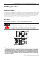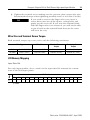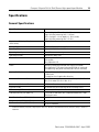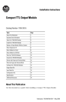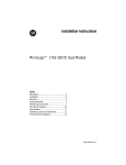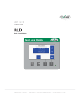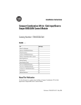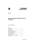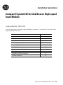
1
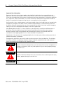
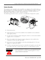
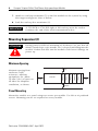
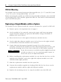
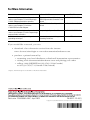
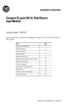
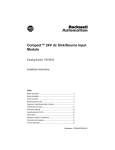
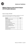
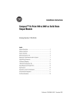
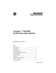
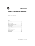
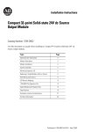
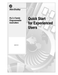
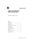
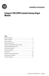
Installation Instructions
Compact 16-point 24V dc Sink/Source High-speed
Input Module
Catalog Number 1769-IQ16F
Use this document as a guide when installing a Compact™ 16-point 24V dc sink/source
high-speed input module.
Topic
Page
Important User Information
2
Module Description
3
Module Installation
4
Mounting Expansion I/O
6
Replacing a Single Module within a System
8
Field Wiring Connections
9
Spare/Replacement Module Parts
12
Specifications
13
Hazardous Location Considerations
15
For More Information
16
Publication 1769-IN064A-EN-P - April 2003
2
Compact 16-point 24V dc Sink/Source High-speed Input Module
Important User Information
Because of the variety of uses for the products described in this publication, those responsible for the
application and use of these products must satisfy themselves that all necessary steps have been taken to
assure that each application and use meets all performance and safety requirements, including any applicable
laws, regulations, codes and standards. In no event will Rockwell Automation be responsible or liable for
indirect or consequential damage resulting from the use or application of these products.
Any illustrations, charts, sample programs, and layout examples shown in this publication are intended solely
for purposes of example. Since there are many variables and requirements associated with any particular
installation, Rockwell Automation does not assume responsibility or liability (to include intellectual property
liability) for actual use based upon the examples shown in this publication.
Allen-Bradley publication SGI-1.1, Safety Guidelines for the Application, Installation and Maintenance of
Solid-State Control (available from your local Rockwell Automation office), describes some important
differences between solid-state equipment and electromechanical devices that should be taken into
consideration when applying products such as those described in this publication.
Reproduction of the contents of this copyrighted publication, in whole or part, without written permission of
Rockwell Automation, is prohibited.
Throughout this publication, notes may be used to make you aware of safety considerations. The following
annotations and their accompanying statements help you to identify a potential hazard, avoid a potential
hazard, and recognize the consequences of a potential hazard:
WARNING
!
Identifies information about practices or circumstances that can cause an explosion in a
hazardous environment, which may lead to personal injury or death, property damage,
or economic loss.
ATTENTION
!
IMPORTANT
Identifies information about practices or circumstances that can lead to personal injury
or death, property damage, or economic loss.
Identifies information that is critical for successful application and understanding of the
product.
Publication 1769-IN064A-EN-P - April 2003
Compact 16-point 24V dc Sink/Source High-speed Input Module
3
Module Description
Item Description
1
2a
3
DANGER
Do Not Remove RTB Under Power
Unless Area is Non-Hazardous
10a
IN 1
IN 3
1
bus lever
(with locking function)
2a
upper panel mounting tab
2b
lower panel mounting tab
3
I/O diagnostic LEDs
4
module door with terminal
identification label
5a
movable bus connector
with female pins
5b
stationary bus connector
with male pins
6
nameplate label
7a
upper
tongue-and-groove slots
7b
lower
tongue-and-groove slots
8a
upper DIN rail latch
8b
lower DIN rail latch
9
write-on label (user ID tag)
10
removable terminal block (RTB)
with finger-safe cover
10a
RTB upper retaining screw
10b
RTB lower retaining screw
IN 0
IN 2
IN 4
IN 5
IN 6
IN 7
10
IN 9
DC
COM1
IN 8
IN 11
IN 10
IN 13
IN 12
IN 15
10b
DC
COM 2
IN 14
Ensure Adjacent
Bus Lever is Unlatched/Latched
Before/After
Removing/Inserting Module
4
1769-IQ16F
1769-IQ16
8a
7a
7a
2b
5a
5b
9
6
7b
7b
8b
Publication 1769-IN064A-EN-P - April 2003
4
Compact 16-point 24V dc Sink/Source High-speed Input Module
Module Installation
Compact I/O is suitable for use in an industrial environment when installed in
accordance with these instructions. Specifically, this equipment is intended for use
in clean, dry environments (Pollution degree 2(1)) and to circuits not exceeding
Over Voltage Category II(2) (IEC 60664-1).(3)
Prevent Electrostatic Discharge
ATTENTION
!
Electrostatic discharge can damage integrated circuits or
semiconductors if you touch bus connector pins. Follow these
guidelines when you handle the module:
•
•
•
•
•
•
Touch a grounded object to discharge static potential.
Wear an approved wrist-strap grounding device.
Do not touch the bus connector or connector pins.
Do not touch circuit components inside the module.
If available, use a static-safe work station.
When not in use, keep the module in its static-shield box.
Remove Power
ATTENTION
!
Remove power before removing or inserting this module.
When you remove or insert a module with power applied, an
electrical arc may occur. An electrical arc can cause personal
injury or property damage by:
– sending an erroneous signal to your system’s field
devices, causing unintended machine motion
– causing an explosion in a hazardous environment
Electrical arcing causes excessive wear to contacts on both the
module and its mating connector. Worn contacts may create
electrical resistance.
(1)
Pollution Degree 2 is an environment where, normally, only non-conductive pollution occurs except that occasionally a
temporary conductivity caused by condensation shall be expected.
(2)
Over Voltage Category II is the load level section of the electrical distribution system. At this level transient voltages are
controlled and do not exceed the impulse voltage capability of the product’s insulation.
(3)
Pollution Degree 2 and Over Voltage Category II are International Electrotechnical Commission (IEC) designations.
Publication 1769-IN064A-EN-P - April 2003
Compact 16-point 24V dc Sink/Source High-speed Input Module
5
System Assembly
The module can be attached to the controller or an adjacent I/O module before or
after mounting. For mounting instructions, see Panel Mounting on page 6, or DIN
Rail Mounting on page 8. To work with a system that is already mounted, see
Replacing a Single Module within a System on page 8.
The following procedure shows you how to assemble the Compact I/O system.
3
4
2
1
6
1
5
1. Disconnect power.
2. Check that the bus lever of the module to be installed is in the unlocked
(fully right) position.
3. Use the upper and lower tongue-and-groove slots (1) to secure the modules
together (or to a controller).
4. Move the module back along the tongue-and-groove slots until the bus
connectors (2) line up with each other.
5. Push the bus lever back slightly to clear the positioning tab (3). Use your
fingers or a small screw driver.
6. To allow communication between the controller and module, move the bus
lever fully to the left (4) until it clicks. Ensure it is locked firmly in place.
ATTENTION
!
When attaching I/O modules, it is very important that the
bus connectors are securely locked together to ensure
proper electrical connection.
Publication 1769-IN064A-EN-P - April 2003
6
Compact 16-point 24V dc Sink/Source High-speed Input Module
7. Attach an end cap terminator (5) to the last module in the system by using
the tongue-and-groove slots as before.
8. Lock the end cap bus terminator (6).
IMPORTANT
A 1769-ECR or 1769-ECL right or left end cap must be used to
terminate the end of the serial communication bus.
Mounting Expansion I/O
ATTENTION
!
During panel or DIN rail mounting of all devices, be sure that all
debris (metal chips, wire strands, etc.) is kept from falling into the
module. Debris that falls into the module could cause damage on
power up.
Minimum Spacing
End Cap
Compact I/O
Compact I/O
Compact I/O
Controller
Side
Compact I/O
Top
Compact I/O
Maintain spacing from
enclosure walls,
wireways, adjacent
equipment, etc. Allow
50 mm (2 in.) of space on
all sides for adequate
ventilation, as shown:
Side
Bottom
Panel Mounting
Mount the module to a panel using two screws per module. Use M4 or #8 panhead
screws. Mounting screws are required on every module.
Publication 1769-IN064A-EN-P - April 2003
Compact 16-point 24V dc Sink/Source High-speed Input Module
7
Panel Mounting Using the Dimensional Template
Right End Cap
Compact I/O
Compact I/O
122.6±0.2
(4.826±0.008)
28.5
(1.12)
35
(1.38)
Compact I/O
132
(5.197)
Host Controller
For more than 2 modules: (number of modules - 1) X 35 mm (1.38 in.)
Refer to host controller documentation for this dimension.
NOTE: All dimensions
are in mm (inches). Hole
spacing tolerance:
±0.4 mm (0.016 in.)
Panel Mounting Procedure Using Modules as a Template
The following procedure allows you to use the assembled modules as a template
for drilling holes in the panel. If you have sophisticated panel mounting equipment,
you can use the dimensional template provided on page 7. Due to module
mounting hole tolerance, it is important to follow these procedures:
1. On a clean work surface, assemble no more than three modules.
2. Using the assembled modules as a template, carefully mark the center of all
module-mounting holes on the panel.
3. Return the assembled modules to the clean work surface, including any
previously mounted modules.
4. Drill and tap the mounting holes for the recommended M4 or #8 screw.
5. Place the modules back on the panel, and check for proper hole alignment.
6. Attach the modules to the panel using the mounting screws.
TIP
If mounting more modules, mount only the last one of
this group and put the others aside. This reduces
remounting time during drilling and tapping of the next
group.
7. Repeat steps 1 to 6 for any remaining modules.
Publication 1769-IN064A-EN-P - April 2003
8
Compact 16-point 24V dc Sink/Source High-speed Input Module
DIN Rail Mounting
The module can be mounted using the following DIN rails: 35 x 7.5 mm (EN 50 022
- 35 x 7.5) or 35 x 15 mm (EN 50 022 - 35 x 15).
Before mounting the module on a DIN rail, close the DIN rail latches. Press the DIN
rail mounting area of the module against the DIN rail. The latches will momentarily
open and lock into place.
Replacing a Single Module within a System
The module can be replaced while the system is mounted to a panel (or DIN rail).
1. Remove power. See important note on page 4.
2. On the module to be removed, remove the upper and lower mounting
screws from the module (or open the DIN latches using a flat-blade or
phillips style screw driver).
3. Move the bus lever to the right to disconnect (unlock) the bus.
4. On the right-side adjacent module, move its bus lever to the right (unlock)
to disconnect it from the module to be removed.
5. Gently slide the disconnected module forward. If you feel excessive
resistance, check that the module has been disconnected from the bus, and
that both mounting screws have been removed (or DIN latches opened).
TIP
It may be necessary to rock the module slightly from front
to back to remove it, or, in a panel-mounted system, to
loosen the screws of adjacent modules.
6. Before installing the replacement module, be sure that the bus lever on the
module to be installed, and on the right-side adjacent module are in the
unlocked (fully right) position.
7. Slide the replacement module into the open slot.
8. Connect the modules together by locking (fully left) the bus levers on the
replacement module and the right-side adjacent module.
9. Replace the mounting screws (or snap the module onto the DIN rail).
Publication 1769-IN064A-EN-P - April 2003
Compact 16-point 24V dc Sink/Source High-speed Input Module
9
Field Wiring Connections
Grounding the Module
This product is intended to be mounted to a well-grounded mounting surface such
as a metal panel. Additional grounding connections from the module’s mounting
tabs or DIN rail (if used), are not required unless the mounting surface cannot be
grounded. Refer to Industrial Automation Wiring and Grounding Guidelines,
Allen-Bradley publication 1770-4.1, for additional information.
Input Wiring
Basic wiring of input devices(1) to the 1769-IQ16F is shown below.
ATTENTION
Miswiring of the module to an AC power source will damage the
module.
!
Be careful when stripping wires. Wire fragments that fall into a
module could cause damage at power up. Once wiring is
complete, ensure the module is free of all metal fragments.
+DC (sinking)
-DC (sourcing)
IN 0
IN 1
IN 2
24V dc
IN 3
IN 4
IN 5
IN 6
IN 7
+DC (sinking)
-DC (sourcing)
DC
COM 1
-DC (sinking)
+DC (sourcing)
IN 9
IN 8
IN 11
24V dc
IN 10
IN 13
IN 12
IN 15
-DC (sinking)
+DC (sourcing)
DC
COM 2
IN 14
(1)
Sinking/Sourcing Inputs - Sourcing/sinking describes the current flow between the I/O
module and the field device. Sourcing I/O circuits supply (source) current to sinking field
devices. Sinking I/O circuits are driven by a current sourcing field device. Field devices
connected to the negative side (DC Common) of the field power supply are sinking field
devices. Field devices connected to the positive side (+V) of the field supply are sourcing
field devices. Europe: DC sinking input and sourcing output module circuits are the
commonly used options.
Publication 1769-IN064A-EN-P - April 2003
10
Compact 16-point 24V dc Sink/Source High-speed Input Module
A removable, write-on label is provided with the module. Remove the label from
the door, mark the identification of each terminal with permanent ink, and slide the
label back into the door. Your markings (ID tag) will be visible when the module
door is closed.
upper retaining
wiring the
finger-safe
terminal
lower retaining
Removing the Finger-Safe Terminal Block
To remove the terminal block, loosen the upper and lower retaining screws. The
terminal block will back away from the module as you remove the screws. When
replacing the terminal block, torque the retaining screws to 0.46 Nm (4.1 in-lbs).
Wiring the Finger-Safe Terminal Block
When wiring the terminal block, keep the finger-safe cover in place.
1. Loosen the terminal screws to be wired.
2. Route the wire under the terminal pressure plate. You can use the bare wire
or a spade lug. The terminals will accept a 6.35 mm (0.25 in.) spade lug.
TIP
The terminal screws are non-captive. Therefore, it is
possible to use a ring lug [max. 1/4” o.d. with a 0.139”
minimum i.d. (M3.5)] with the module.
Publication 1769-IN064A-EN-P - April 2003
Compact 16-point 24V dc Sink/Source High-speed Input Module
11
3. Tighten the terminal screw making sure the pressure plate secures the wire.
Recommended torque when tightening terminal screws is 0.68 Nm (6 in-lbs).
If you need to remove the finger-safe cover, insert a
screw driver into one of the square, wiring holes and
gently pry the cover off. If you wire the terminal block
with the finger-safe cover removed, you will not be able
to put it back on the terminal block because the wires
will be in the way.
TIP
Wire Size and Terminal Screw Torque
Each terminal accepts up to two wires with the following restrictions:
Wire Type
Wire Size
Terminal Screw
Torque
Retaining Screw
Torque
Solid
Cu-90°C (194°F)
#14 to #22 AWG
0.68 Nm (6 in-lbs)
0.46 Nm (4.1 in-lbs)
Stranded
Cu-90°C (194°F)
#16 to #22 AWG
0.68 Nm (6 in-lbs)
0.46 Nm (4.1 in-lbs)
I/O Memory Mapping
Input Data File
For each input module, slot x, word 0 in the input data file contains the current
state of the field input points.
Word
Bit Position
0
15
r
14
r
13
r
12
r
11
r
10
r
9
r
8
r
7
r
6
r
5
r
4
r
3
r
2
r
1
r
0
r
r= read
Publication 1769-IN064A-EN-P - April 2003
12
Compact 16-point 24V dc Sink/Source High-speed Input Module
1769-IQ16F Configuration File
The read/writable configuration data file allows the setup of the digital filter settings
for each of the two input groups. Group 0 is inputs 0 - 7, Group 1 is inputs 8 - 15.
Word
The manipulation of the bits from this file is normally done with programming
software (e.g., RSLogix 500, RSNetworx for DeviceNet, etc.) during initial
configuration of the system. In that case, graphical screens are provided via the
programmer to simplify configuration. However, some systems (e.g., 1769-ADN
DeviceNet Adapter) also allow the bits to be altered as part of the control program
using communication rungs. In that case, it is necessary to understand the bit
arrangement.
0
Bit Position
15
14
13
12
Filter Time On to Off
Group 1
11
10
9
8
Filter Time Off to On
Group 1
7
6
5
4
Filter Time On to Off
Group 0
1
0000000000000000
2
0000000000000000
3
0000000000000000
(1)
3
2
1
0
Filter Time Off to On
Group 0
Filter Time(1)
Bit Setting
2.0 msec
0010
1.0 msec
0011
0.5 msec
0100
0.1 msec
0101
0.0 msec
0110
Filter Time: Word 0, the Filter Time configures
the ON to OFF and OFF to ON hardware delay
times for each input group.
Spare/Replacement Module Parts
•
•
•
Terminal Block:
Door Label:
Door:
Publication 1769-IN064A-EN-P - April 2003
1769-RTBN18 (1 per kit)
1769-RL1 (2 per kit)
1769-RD (2 per kit)
Compact 16-point 24V dc Sink/Source High-speed Input Module
13
Specifications
General Specifications
Specification
Value
Dimensions
118 mm (height) x 87 mm (depth) x 35 mm (width)
height including mounting tabs is 138 mm
4.65 in. (height) x 3.43 in (depth) x 1.38 in (width)
height including mounting tabs is 5.43 in.
Approximate Shipping Weight
(with carton)
270g (0.6 lbs.)
Storage Temperature
-40°C to +85°C (-40°F to +185°F)
Operating Temperature
0°C to +60°C (32°F to +140°F)
Operating Humidity
5% to 95% non-condensing
Operating Altitude
2000 meters (6561 feet)
Vibration
Operating: 10 to 500 Hz, 5G, 0.030 inches maximum
peak-to-peak
Relay Operation: 2G
Shock
Operating: 30G panel mounted (20G DIN rail mounted)
Relay Operation: 7.5G panel mounted (5G DIN rail mounted)
Non-Operating: 40G panel mounted (30G DIN rail mounted)
Agency Certification
C-UL certified (under CSA C22.2 No. 142)
UL 508 listed
CE compliant for all applicable directives
Hazardous Environment Class
Class I, Division 2, Hazardous Location, Groups A, B, C, D (UL
1604, C-UL under CSA C22.2 No. 213)
Radiated and Conducted Emissions
EN50081-2 Class A
Electrical /EMC:
The module has passed testing at the following levels:
ESD Immunity (IEC1000-4-2)
4kV contact, 8 kV air, 4 kV indirect
Radiated Immunity (IEC1000-4-3)
10 V/m, 80 to 1000 MHz, 80% amplitude modulation, +900
MHz keyed carrier
Fast Transient Burst (IEC1000-4-4)
2 kV, 5 kHz
Surge Immunity (IEC1000-4-5)
2 kV common mode, 1 kV differential mode
Conducted Immunity (IEC1000-4-6)
10V, 0.15 to 80 MHz(1)
(1)
Conducted Immunity frequency range may be 150 kHz to 30 MHz if the Radiated Immunity frequency range is 30 MHz to
1000 MHz.
Publication 1769-IN064A-EN-P - April 2003
14
Compact 16-point 24V dc Sink/Source High-speed Input Module
Input Specifications
Specification
1769-IQ16F
Voltage Category
24V dc (sink/source(1))
Operating Voltage Range
10 to 30V dc at 30°C (86°F)
10 to 26.4V dc at 60°C (140°F)
Number of Inputs
16
Bus Current Draw (max.)
110 mA at 5V dc (0.55W)
Heat Dissipation
3.55 Total Watts (The Watts per point, plus the minimum Watts, with
all points energized.)
Digital Filter
OFF to ON
Hardware Delay
0s, 100µs, 500µs, 1ms, 2ms
ON to OFF
0s, 100µs, 500µs, 1ms, 2ms
OFF to ON
100µs (typical)
300µs (maximum)
ON to OFF
250µs (typical)
1ms (maximum)
Off-State Voltage (max.)
5V dc
Off-State Current (max.)
1.5 mA
On-State Voltage (min.)
10V dc
On-State Current (min.)
2.0 mA
Inrush Current (max.)
250 mA
Nominal Impedance
3K Ω
IEC Input Compatibility
Type 1+
Power Supply Distance Rating
8 (The module may not be more than 8 modules away from the power
supply or controller.)
Input Point to Bus (Compact Bus)
Isolation
Verified by one of the following dielectric tests: 1200V ac for 1 sec. or
1697V dc for 1 sec.
75V dc working voltage (IEC Class 2 reinforced insulation)
Isolated Groups
Group 1: inputs 0 to 7
Group 2: inputs 8 to 15
Isolated groups operate in either sink or source configurations.
Input Group to Input Group Isolation
Verified by one of the following dielectric tests: 1200V ac for 1 sec. or
1697V dc for 1 sec.
75V dc working voltage (IEC Class 2 reinforced insulation)
Vendor I.D. Code
1
Product Type Code
7
Product Code
69
(1)
Sinking/Sourcing Inputs - Sourcing/sinking describes the current flow between the I/O module and the field device.
Sourcing I/O circuits supply (source) current to sinking field devices. Sinking I/O circuits are driven by a current sourcing field
device. Field devices connected to the negative side (DC Common) of the field power supply are sinking field devices. Field
devices connected to the positive side (+V) of the field supply are sourcing field devices. Europe: DC sinking input and
sourcing output module circuits are the commonly used options.
Publication 1769-IN064A-EN-P - April 2003
Compact 16-point 24V dc Sink/Source High-speed Input Module
15
Hazardous Location Considerations
This equipment is suitable for use in Class I, Division 2, Groups A, B, C, D or
non-hazardous locations only. The following ATTENTION statement applies to use
in hazardous locations.
ATTENTION
EXPLOSION HAZARD
–
!
–
–
–
–
Substitution of components may impair suitability for Class I,
Division 2.
Do not replace components or disconnect equipment unless
power has been switched off or the area is known to be
non-hazardous.
Do not connect or disconnect components unless power has
been switched off or the area is known to be
non-hazardous.
This product must be installed in an enclosure.
All wiring must comply with N.E.C. article 501-4(b).
Environnements dangereux
Cet équipement est conçu pour être utilisé dans des environnements de Classe 1,
Division 2, Groupes A, B, C, D ou non dangereux. La mise en garde suivante
s’applique à une utilisation dans des environnements dangereux.
ATTENTION
DANGER D’EXPLOSION
–
!
La substitution de composants peut rendre cet équipement
impropre à une utilisation en environnement de Classe 1,
Division 2.
– Ne pas remplacer de composants ou déconnecter
l'équipement sans s'être assuré que l'alimentation est coupée
et que l'environnement est classé non dangereux.
– Ne pas connecter ou déconnecter des composants sans
s'être assuré que l'alimentation est coupée ou que
l'environnement est classé non dangereux.
– Ce produit doit être installé dans une armoire.
Publication 1769-IN064A-EN-P - April 2003
For More Information
For
Refer to this Document
Pub. No.
a more detailed description of how to install MicroLogix 1200 and MicroLogix
and use your Compact I/O with MicroLogix
1500 Programmable Controllers User
1200 & 1500 programmable controller
Manual
1764-RM001B-US-P
a more detailed description of how to install 1769-ADN DeviceNet Adapter User
and use your Compact I/O with the
Manual
1769-ADN DeviceNet Adapter
1769-UM001A-US-P
a more detailed description of how to install CompactLogix System User Manual
and use your Compact I/O with CompactLogix
programmable controllers
1769-UM007C-EN-P
more information on proper wiring and
grounding techniques
Industrial Automation Wiring and
Grounding Guidelines
1770-4.1
If you would like a manual, you can:
• download a free electronic version from the internet:
www.ab.com/micrologix or www.theautomationbookstore.com
• purchase a printed manual by:
– contacting your local distributor or Rockwell Automation representative
– visiting www.theautomationbookstore.com and placing your order
– calling 1.800.9NEWLIT(800.963.9548) (USA/Canada)
or 001.330.725.1574 (Outside USA/Canada)
Compact and MicroLogix are trademarks of Rockwell Automation.
Publication 1769-IN064A-EN-P - April 2003
PN 40071-151-01(1)
Copyright © 2003 Rockwell Automation, Inc. All rights reserved. Printed in the U.S.A.
´H'+S!¶1z¨