1
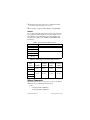
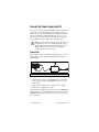
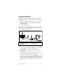
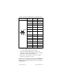
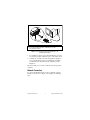
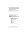
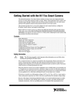
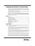
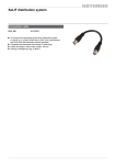
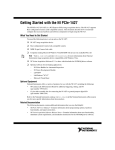
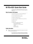
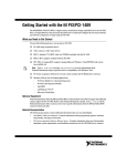
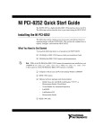
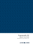
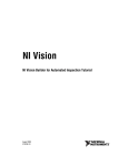
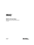
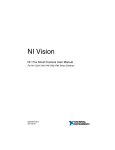
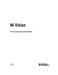
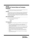
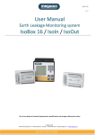
Getting Started with the
NI 17xx Smart Camera
The National Instruments 17xx Smart Camera combines an image
sensor and a high-performance processor to return either
inspection results or images. While a typical industrial camera
acquires and transmits images through a standard camera bus for
processing on another device, the smart camera performs both
acquisition and processing operations directly on the smart camera.
This document describes how to set up and configure the smart
camera hardware, configure the IP address, install software, and
acquire an initial image.
Refer to the NI 17xx Smart Camera User Manual for information
about specific features and specifications of the smart camera.
Select Start»All Programs»National Instruments»Vision»
Documentation»NI-IMAQ to access the NI 17xx Smart Camera
User Manual after configuring the smart camera using the
procedures described in this document.
Unpack and Verify Components
Remove the NI Smart Camera from the package and inspect the
device for any sign of damage. Notify National Instruments if the
device appears damaged in any way. Do not use a damaged device.
For safety and compliance information, refer to the specifications
in the NI 17xx Smart Camera User Manual.
Required Components
This section describes the hardware and software components
necessary to set up and use the NI Smart Camera.
Hardware
The following hardware components are included in the NI Smart
Camera kit:
❑
NI 17xx Smart Camera
❑
5-position lighting connector (additional/replacement plugs
for use with the lighting connector are available from NI,
part number 780260-01)
In addition to the items included in the smart camera kit, the
following components are necessary to set up and configure the
smart camera:
❑
One or two CAT 5 10/100Base-TX or CAT 5e or CAT 6
1000Base-T Ethernet cables. One Ethernet cable is required to
connect the smart camera directly to the development
computer. Two Ethernet cables are required to connect the
smart camera to the development computer through a network.
Note A CAT 5e or CAT 6 1000Base-T Ethernet cable is
required to achieve maximum 1,000 Mbps (Gigabit)
Ethernet performance. CAT 5e and CAT 6 Ethernet
cables adhere to higher electrical standards required for
Gigabit Ethernet communication. CAT 5 cables are not
guaranteed to meet the necessary electrical requirements.
While CAT 5 cables may appear to work at 1,000 Mbps
in some installations, CAT 5 cables are likely to cause
increased bit errors resulting in degraded or unreliable
network performance.
❑
One of the following power supply options:
Use the smart camera only with a 24 VDC, UL
listed, limited power source (LPS) supply. The power
supply will bear the UL listed mark, LPS. The power
supply must also meet any safety and compliance
requirements for the country of use.
Caution
–
NI desktop power supply (part number 780237-01) and
power supply cord. Refer to ni.com for the power supply
cord part number specific to your region and ordering
information.
–
Any 24 VDC, +20%/–15% (IEC 1311) power supply and
one of the following cable options for connecting to the
power supply and I/O:
•
15-pin D-SUB pigtail cable, 5 m (part number
197818-05)
•
15-pin D-SUB to 15-pin D-SUB cable, 2 m
(part number 197817-02) or 5 m (part number
197817-05), and a 15-pin D-SUB terminal block
Getting Started with the NI 17xx
2
ni.com
❑
❑
Standard C-mount lens. Other lenses available from NI are
listed in the Optional Components section.
Development computer running Windows Vista/XP/2000
Software
Use one of the following application development environments to
develop NI Smart Camera applications. Refer to Table 1 for the
Vision Builder for Automated Inspection (Vision Builder AI)
information or to Table 2 for LabVIEW and LabVIEW module
information.
Table 1. NI Vision Builder AI Minimum Versions
NI Smart Camera
NI Vision Builder AI Version (Included)
NI 1722
3.5 or later
NI 1742
NI 1744
3.6 or later
NI 1762
NI 1764
Table 2. LabVIEW and Necessary Modules Minimum Versions
Smart
Camera
NI 1722
NI 1742
NI 1744
NI 1762
LabVIEW
LabVIEW
Real-Time
Vision
Development
Module
Vision
Acquisition
Software
8.5
or later
8.5
or later
8.5
or later
8.6
or later
8.5.1
or later
8.5.1
or later
8.6
or later
8.6
or later
NI 1764
Optional Components
National Instruments offers a variety of accessories for use with the
NI Smart Camera, including the following items:
•
Lenses
–
8 mm (part number 780024-01)
–
12 mm (part number 780025-01)
© National Instruments Corp.
3
Getting Started with the NI 17xx
•
•
•
–
16 mm (part number 780026-01)
–
25 mm (part number 780027-01)
Current controlled lights
–
Back light (part number 780221-01)
–
Ring light (part number 780222-01)
–
Broad area linear light array (part number 780223-01)
–
Spot light (part number 780224-01)
Mounting brackets
–
Tripod adapter plate (part number 780239-01)
–
Panel mount (part number 780240-01)
Accessories
–
NI 17xx unshielded screw terminal breakout with 2 m
cable (part number 780261-01)
–
NI Smart Camera I/O accessory (part number 780443-01)
Visit ni.com or contact the branch office nearest you for more
information about these and other products.
Connect the Lens and Lighting
Complete the following steps to connect a standard C-mount lens
and external lighting accessories to the NI Smart Camera.
1. Remove the lens cover from the smart camera.
2. Gently align the threads on the base of the lens with the threads
on the sensor opening, and twist clockwise until the lens is
securely attached.
Lighting
The NI Smart Camera offers two options for controlling a light—a
Direct Drive internal lighting controller, or 5 V TTL or 24 V
external strobe generation for use with a third-party lighting
controller. Refer to the NI 17xx Smart Camera User Manual for
information about using the smart camera with a light.
Note The Direct Drive lighting controller is not available
on NI 1722 smart cameras. NI 1722 smart cameras
support only 5 V TTL or 24 V external strobe generation.
Getting Started with the NI 17xx
4
ni.com
Connect the Power Supply and I/O
To connect a power supply to the NI Smart Camera, complete the
steps listed in one of the following sections. Refer to the Power
Only section to connect the NI desktop power supply directly to the
smart camera with no additional I/O. Refer to the Power with
Additional I/O section to connect a third-party power supply or
if your application requires I/O, such as a trigger signal.
Use the smart camera only with a 24 VDC, UL
listed, limited power source (LPS) supply. The power
supply will bear the UL listed mark, LPS. The power
supply must also meet any safety and compliance
requirements for the country of use.
Caution
Power Only
Refer to Figure 1 while completing the following steps to connect
the NI desktop power supply to the NI Smart Camera with no
additional I/O.
2
1
1 NI Smart Camera
2 Power Supply
Figure 1. Connecting the NI Smart Camera to the NI Desktop Power Supply
1. Connect and secure the 15-pin D-SUB connector on the NI
desktop power supply to the POWER-I/O connector on the
smart camera.
2. Plug the power supply power cord into the power supply.
3. Plug the power supply into an outlet.
When power is first applied to the smart camera, the POWER LED
flashes red for one second while internal systems power up. The
POWER LED then lights green when power is correctly wired to
the smart camera.
© National Instruments Corp.
5
Getting Started with the NI 17xx
Power with Additional I/O
National Instruments provides the following two cable options for
connecting a third-party power supply and I/O to the NI Smart
Camera.
•
Terminal block with a 15-pin D-SUB connector, such as the
NI Smart Camera I/O Accessory, and a 15-pin D-SUB to
15-pin D-SUB cable
•
15-pin D-SUB pigtail cable
Refer to Figure 2 while completing the following steps to connect
a third-party power supply and I/O to the smart camera using either
a terminal block or the pigtail cable.
1
3
2
1 NI Smart Camera
2 15-Pin D-SUB to 15-Pin
D-SUB Cable
4
3 Optional Terminal Block
4 Power Supply
Figure 2. Connecting the NI Smart Camera to a Third-Party Power Supply
1. Connect and secure the 15-pin D-SUB connector on your cable
to the POWER-I/O connector on the smart camera.
2. If you are using a terminal block, connect the cable to the
terminal block.
3. Connect the +24 V signal from the cable or terminal block to
the corresponding signal on the power supply.
Table 3 shows the pin locations for the POWER-I/O connector
and lists the signal names and pin numbers. The table also lists
wire colors for the National Instruments 15-pin D-SUB pigtail
cable. Cables from another vendor may have different wire
colors.
Getting Started with the NI 17xx
6
ni.com
Table 3. NI Smart Camera POWER-I/O Connector Signal Descriptions
Connector Diagram
11
6
15 (COM)
10
1
5 (+24 V)
Signal Name
Pin Number
Wire Color
+24 V
5
Red
COM
15
Black
RS_232TXD
10
Pink
RS_232RXD
14
Black/White
TrigIn+
IsoIn(0)+
2
Brown
IsoIn(1)+
8
Orange
TrigIn–
IsoIn(0)–
IsoIn(1)–
12
Light Green
IsoOut(0)+
6
Yellow
IsoOut(0)–
1
Green
IsoOut(1)+
11
Light Blue
IsoOut(1)–
7
Gray
PhaseA+
3
Blue
PhaseA–
13
Brown/White
PhaseB+
9
Purple
PhaseB–
4
White
4. Connect the COM signal from the cable or terminal block to
the corresponding signal on the power supply.
5. Connect any additional I/O signals necessary for your
application to the appropriate signal on the cable or terminal
block. Refer to Table 3 for pin information.
6. If necessary, connect the power cord to the power supply.
7. Plug the power supply into an outlet.
When power is first applied to the smart camera, the POWER LED
flashes red for one second while internal systems power up. The
POWER LED then lights green when power is correctly wired to
the smart camera.
© National Instruments Corp.
7
Getting Started with the NI 17xx
Connect to the Development Computer
The NI Smart Camera can connect to the development computer
directly or through a network using an Ethernet cable. The smart
camera provides automatic MDI/MDI-X correction, so you can use
either a standard Ethernet cable or a crossover Ethernet cable
to connect to the development computer. If the development
computer is configured on a network, you must configure the smart
camera on the same network subnet as the development computer
to connect through the network.
To prevent data loss and to maintain the integrity
of your Ethernet installation, do not use a cable longer
than 100 m. National Instruments recommends using a
shielded twisted pair Ethernet cable for maximum signal
integrity.
Caution
Firewall Configuration
If your firewall is controlled remotely or you are unsure about
configuring the firewall, contact your network administrator. Refer
to Appendix B, Troubleshooting, of the NI 17xx Smart Camera
User Manual to troubleshoot network configuration issues.
Direct Connection
To connect the NI Smart Camera directly to the development
computer, refer to Figure 3 and complete the following steps.
Getting Started with the NI 17xx
8
ni.com
2
1
1 Connecting an Ethernet Cable to Port 1 on the NI Smart Camera
2 Connecting an Ethernet Cable to an Ethernet Port on the
Development Computer
Figure 3. Connecting the NI Smart Camera Directly to the
Development Computer
1. Use an Ethernet cable to connect from the Ethernet port on the
development computer to Ethernet port 1 on the smart camera.
2. Configure the network card on the development computer to
use a static IP address. Refer to your Windows networking
documentation for information about configuring a static
IP address.
The smart camera is now connected directly to the development
computer.
Network Connection
To connect the NI Smart Camera to the development computer
through a network, refer to Figure 4 and complete the following
steps.
© National Instruments Corp.
9
Getting Started with the NI 17xx
3
2
1
1 Connecting an Ethernet Cable to Port 1 on the NI Smart Camera
2 Ethernet Hub or Other Network Port
3 Connecting an Ethernet Cable to an Ethernet Port on the
Development Computer
Figure 4. Connecting the NI Smart Camera to the Development Computer
Through a Network
1. Verify that the development computer is connected to the
network and powered on.
2. Using an Ethernet cable, connect from an Ethernet hub or other
network port to Ethernet port 1 on the smart camera.
The smart camera is now connected to the development computer
through a network.
Subnet Considerations
To configure the NI Smart Camera, it must reside on the same
subnet as the development computer. Once the smart camera is
configured, as described in the Configuring the NI Smart Camera
with Vision Builder AI section and the Configuring the NI Smart
Camera with LabVIEW section, other subnets can be used to
access it.
To use the smart camera on a subnet other than the one on which
the development computer resides, first connect and configure the
smart camera on the same subnet as the development computer.
Next, physically move the smart camera to the other subnet.
Contact your network administrator for assistance in determining
which network ports reside on the same subnet.
Getting Started with the NI 17xx
10
ni.com
Software Options
National Instruments provides two options for developing
applications for the NI Smart Camera.
Vision Builder
for
Automated Inspection
•
or
LabVIEW
LabVIEW Real-Time Module
NI Vision Development Module
NI Vision Acquisition Software
NI Vision Builder for Automated Inspection (Vision
Builder AI)—Interactive, menu-driven configuration software
for developing, benchmarking, and deploying machine vision
applications. The latest version of Vision Builder AI is
included with the smart camera.
To use Vision Builder AI to configure the smart camera and
develop your application, complete the instructions in the
Configuring the NI Smart Camera with Vision Builder AI
section of this document.
•
NI LabVIEW—Graphical programming environment for
developing flexible and scalable applications. The following
add-on modules are required for developing machine vision
applications:
–
LabVIEW Real-Time Module—Programming library
for developing distributed, deterministic applications.
–
NI Vision Development Module—Programming library
for developing machine vision and scientific imaging
applications.
–
NI Vision Acquisition Software—Includes NI-IMAQ
driver software for acquiring images and controlling I/O
using the smart camera. The latest version of NI Vision
Acquisition software is included with the smart camera.
To use LabVIEW to configure the smart camera and develop
your application, complete the instructions in the Configuring
the NI Smart Camera with LabVIEW section of this document.
© National Instruments Corp.
11
Getting Started with the NI 17xx
The installation and configuration process for each
development environment is different. Complete only the
instructions for your chosen development environment.
Note
Configuring the NI Smart Camera
with Vision Builder AI
Complete the following steps to install Vision Builder AI and
configure the NI Smart Camera.
1. Install and activate Vision Builder AI on the development
computer. Refer to the NI Vision Builder for Automated
Inspection Readme for installation instructions.
2. Launch Vision Builder AI.
3. On the Vision Builder AI welcome screen, select the NI Smart
Camera in the list of targets.
If the NI Smart Camera does not appear in the list of targets,
refer to the Subnet Considerations section of this document
and Appendix B, Troubleshooting, of the NI 17xx Smart
Camera User Manual for information about subnets and
troubleshooting smart camera configuration issues.
4. Click Install Software. The Remote Target Configuration
Wizard launches in a new window.
5. In the Name field, enter a name for the device. Use the
Description field to enter any additional information or a brief
description of the device.
Device names are limited to 31 characters with no spaces or
special characters, except hyphens. The first and last characters
must be alphanumeric.
6. Click Next.
Configure the IP Address
1. If the network is configured to issue IP addresses using DHCP,
select Obtain IP address from DHCP server. Otherwise,
configure the IP address manually by selecting Edit the IP
settings and clicking Suggest Values.
2. If you want to prevent other users from configuring the smart
camera, select Enable Password and click Set Password to
set up password protection.
3. Click Next.
Getting Started with the NI 17xx
12
ni.com
Install Software on the NI Smart Camera
Complete the following steps to install software from the
development computer to the NI Smart Camera.
1. In the Remote Target Configuration Wizard, enable the
Update Target Software checkbox.
2. Click the Browse button next to the Software Image to Install
on the Target control.
3. Navigate to the Vision Builder AI software image you want to
use, and click OK. Software images provided by National
Instruments are installed to the <Vision Builder AI>\
RT Images directory, where <Vision Builder AI> is the
location where Vision Builder AI is installed.
4. Click OK to apply the IP configuration settings and download
software to the smart camera.
5. Click OK to close the Remote Target Configuration Successful
dialog box.
Acquire an Image
Complete the following steps to acquire an image using Vision
Builder AI.
1. On the Vision Builder AI welcome screen, select the NI Smart
Camera in the list of targets.
2. Click Acquire Image (Smart Camera) Example to open the
image acquisition example in the Vision Builder AI
Configuration Interface.
3. Click the Run State Once button to acquire a single image.
4. In the State Configuration Window, select the Acquire Image
(Smart Camera) step.
5. Click the Edit Step button. The property page for the step
opens.
6. Use the controls on the Main, Trigger, Lighting, and
Advanced tabs to configure any additional settings necessary
for your application.
7. Click OK to save the step configuration.
The smart camera is now configured and acquiring images. Use
Vision Builder AI to add and configure additional inspection steps
to create your application. Refer to the Where to Go from Here
section for a list of documentation and other resources to help you
set up and use the smart camera in an application.
© National Instruments Corp.
13
Getting Started with the NI 17xx
Configuring the NI Smart Camera
with LabVIEW
Complete the following steps to install LabVIEW, the LabVIEW
Real-Time Module, the NI Vision Development Module, and
NI Vision Acquisition Software and configure the NI Smart
Camera. Install the software in the following order:
1. LabVIEW—Refer to the LabVIEW Release Notes for
installation instructions for LabVIEW and system
requirements for the LabVIEW software. Refer to the
LabVIEW Upgrade Notes for additional information about
upgrading to the most recent version of LabVIEW.
Documentation for LabVIEW is available by selecting
Start»All Programs»National Instruments»LabVIEW»
LabVIEW Manuals.
2. LabVIEW Real-Time Module—Refer to the LabVIEW
Real-Time Module Release and Upgrade Notes for installation
instructions and information about getting started with the
LabVIEW Real-Time Module.
Documentation for the LabVIEW Real-Time Module is
available by selecting Start»All Programs»National
Instruments»LabVIEW»LabVIEW Manuals.
3. NI-IMAQ—Refer to the NI Vision Acquisition Software
Release Notes on the NI Vision Acquisition Software
installation media for system requirements and installation
instructions for the NI-IMAQ driver.
Documentation for the NI-IMAQ driver software is available
by selecting Start»All Programs»National Instruments»
Vision»Documentation»NI-IMAQ.
4. NI Vision Development Module—Refer to the NI Vision
Development Module Readme on the NI Vision Development
Module installation media for system requirements and
installation instructions.
Documentation for the NI Vision Development Module is
available by selecting Start»All Programs»National
Instruments»Vision»Documentation»NI Vision.
Getting Started with the NI 17xx
14
ni.com
Configure the IP Address
You can assign the NI Smart Camera a static IP address or
configure it to automatically acquire an IP address from a DHCP
server. Complete the following steps to configure an IP address for
the NI Smart Camera.
1. Launch Measurement & Automation Explorer (MAX), the
National Instruments configuration utility, by double-clicking
the Measurement & Automation icon on the desktop, or
selecting Start»All Programs»National Instruments»
Measurement & Automation.
2. Expand the Remote Systems branch of the configuration tree,
and select the device you want to configure. To uniquely
identify multiple unconfigured devices, connect and configure
one device at a time.
Refer to the Subnet Considerations section of this document
and Appendix B, Troubleshooting, of the NI 17xx Smart
Camera User Manual for information about subnets and
troubleshooting smart camera configuration issues.
3. In the Name field, enter a name for the device. Use the
Comment field to enter any additional information or a brief
description of the device.
4. Device names are limited to 31 characters with no spaces or
special characters, except hyphens. The first and last characters
must be alphanumeric.
5. Verify the IP address configuration. The IP address is either
a network address, an automatic private IP address
(169.254.x.x), or 0.0.0.0, depending on how the network
is configured to issue network addresses.
•
If the network is configured to issue IP addresses using
DHCP, select Obtain IP address from DHCP server.
•
Otherwise, configure the IP address manually. Select Edit
the IP settings, click Suggest Values, and click OK.
Note If the smart camera IP address is 169.254.x.x or
0.0.0.0, the smart camera is only accessible from the
local subnet. To access the smart camera from a remote
subnet, configure the smart camera to obtain an IP
address from a DHCP server or manually assign a static
IP address.
© National Instruments Corp.
15
Getting Started with the NI 17xx
6. If you want to prevent other users from resetting the smart
camera, click the Lock button on the MAX toolbar to set up
password protection for the smart camera. To require users to
enter the password before restarting the smart camera, enable
the Password-protect Resets checkbox.
7. Click Apply on the MAX toolbar.
8. When prompted, click Yes to restart the smart camera.
The initialization process may take several minutes.
Install Software on the NI Smart Camera
Complete the following steps to install software from the
development computer to the NI Smart Camera.
1. In the Remote Systems branch of the MAX configuration tree,
expand the folder for your device and select Software.
2. Click Add/Remove Software on the MAX toolbar to launch
the LabVIEW Real-Time Software Wizard.
3. Select LabVIEW Real-Time, NI Vision RT, NI-IMAQ RT,
NI-IMAQ Server, and any additional software necessary for
your application, as shown in Figure 6.
Figure 5. Selecting Software to Install in MAX
4. Click Next.
5. Verify your software installation choices, and click Next.
6. When the installation is complete, click Finish.
Getting Started with the NI 17xx
16
ni.com
Acquire an Image
Complete the following steps to acquire an image using MAX.
1. In the Remote Systems branch of the MAX configuration tree,
expand the folder for your device.
2. Click img0:NI 17xx, where 17xx is replaced by the actual
model number of your smart camera.
3. Click Snap to acquire a single image, or click Grab to acquire
continuous images. Click Grab again to stop a continuous
acquisition.
4. Use the controls on the Sensor, Triggering, Lighting, and
LUT tabs to adjust the acquisition settings.
The NI Smart Camera is now configured and acquiring images.
Use LabVIEW to create your application. Refer to the Where to Go
from Here section for a list of documentation and other resources
to help you set up and use the smart camera in an application.
Where to Go from Here
The following documents and resources contain information you
may find helpful as you set up and use the NI Smart Camera in an
application.
Refer to the NI 17xx Smart Camera User Manual for detailed
information about:
•
Power and I/O requirements
•
The image sensor and scan modes
•
Exposure time and field of view
•
The Direct Drive Lighting Controller and external lighting
controllers
•
Acquiring images with the smart camera and calculating the
maximum frame rate
•
Understanding the LED indicators and configuring the DIP
switches
•
Ethernet connections
•
Smart camera specifications
•
Troubleshooting network, firewall, software, and power issues
© National Instruments Corp.
17
Getting Started with the NI 17xx
Additional Resources for Vision Builder for
Automated Inspection Users
Refer to the NI Vision Builder for Automated Inspection Tutorial
to learn how to perform basic machine vision techniques using
Vision Builder AI. You can access the NI Vision Builder for
Automated Inspection Tutorial and other documentation by
selecting Start»All Programs»National Instruments»Vision
Builder AI»Documentation. You can also access context help
within Vision Builder AI by clicking the Show Context Help
button on the Vision Builder AI toolbar.
Examples of common Vision Builder AI inspections are installed
to the <Vision Builder AI>\Examples directory.
Visit the NI Developer Zone at ni.com/zone for the latest
example programs, tutorials, technical presentations, and a
community area where you can share ideas, questions, and source
code with developers around the world.
Additional Resources for LabVIEW Users
Documentation for LabVIEW and the LabVIEW Real-Time
Module is available from the Help menu on the LabVIEW toolbar.
You can access documentation for the NI Vision Development
Module by selecting Start»All Programs»National
Instruments»Vision»Documentation»NI Vision.
Documentation for the NI-IMAQ driver software is available by
selecting Start»All Programs»National Instruments»Vision»
Documentation»NI-IMAQ.
Documentation for the MAX configuration software is available
from the Help menu on the MAX toolbar. Specific information
about using MAX with NI Vision hardware is available by
selecting Help»Help Topics»NI Vision»NI-IMAQ.
Examples of image acquisitions and common machine vision
inspections are installed to the <LabVIEW>\Examples\IMAQ and
<LabVIEW>\Examples\Vision directories, where <LabVIEW>
is the location where LabVIEW is installed.
Visit the NI Developer Zone at ni.com/zone for the latest
example programs, tutorials, technical presentations, and a
community area where you can share ideas, questions, and source
code with developers around the world.
Getting Started with the NI 17xx
18
ni.com
Safety Information
The following paragraphs contain important
safety information you must follow when installing and
operating the NI smart camera.
Caution
Do not operate the device in a manner not specified in the
documentation. Misuse of the device may result in a hazard and
may compromise the safety protection built into the device. If the
device is damaged, turn it off and do not use it until service-trained
personnel can check its safety. If necessary, return the device to
National Instruments for repair.
Keep away from live circuits. Do not remove equipment covers or
shields unless you are trained to do so. If signal wires are
connected to the device, hazardous voltages can exist even when
the equipment is turned off. To avoid a shock hazard, do not
perform procedures involving cover or shield removal unless you
are qualified to do so. Disconnect all field power prior to removing
covers or shields.
If the device is rated for use with hazardous voltages (>30 Vrms,
42.4 Vpk, or 60 Vdc), it may require a safety earth-ground
connection wire. Refer to the device specifications for maximum
voltage ratings.
Because of the danger of introducing additional hazards, do not
install unauthorized parts or modify the device. Use the device
only with the chassis, modules, accessories, and cables specified in
the installation instructions. All covers and filler panels must be
installed while operating the device.
Do not operate the device in an explosive atmosphere or where
flammable gases or fumes may be present. Operate the device only
at or below the pollution degree stated in the specifications.
Pollution consists of any foreign matter—solid, liquid, or
gas—that may reduce dielectric strength or surface resistivity.
The following is a description of pollution degrees.
•
Pollution Degree 1—No pollution or only dry, nonconductive
pollution occurs. The pollution has no effect.
•
Pollution Degree 2—Normally only nonconductive pollution
occurs. Occasionally, nonconductive pollution becomes
conductive because of condensation.
© National Instruments Corp.
19
Getting Started with the NI 17xx
•
Pollution Degree 3—Conductive pollution or dry,
nonconductive pollution occurs. Nonconductive pollution
becomes conductive because of condensation.
Clean the device and accessories by brushing off light dust with a
soft, nonmetallic brush. Remove other contaminants with a stiff,
nonmetallic brush. The unit must be completely dry and free from
contaminants before returning it to service.
You must insulate signal connections for the maximum voltage for
which the device is rated. Do not exceed the maximum ratings for
the device. Remove power from signal lines before connection to
or disconnection from the device.
National Instruments measurement products
may be classified as either Measurement Category I or II.
Operate products at or below the Measurement Category
level specified in the hardware specifications.
Caution
Measurement Category1: Measurement circuits are subjected to
working voltages2 and transient stresses (overvoltage) from the
circuit to which they are connected during measurement or test.
Measurement (Installation3) Category establishes standardized
impulse withstand voltage levels that commonly occur in electrical
distribution systems. The following is a description of
Measurement Categories:
•
Measurement Category I is for measurements performed on
circuits not directly connected to the electrical distribution
system referred to as MAINS4 voltage. This category is for
measurements of voltages from specially protected secondary
circuits. Such voltage measurements include signal levels,
special equipment, limited-energy parts of equipment, circuits
powered by regulated low-voltage sources, and electronics.
•
Measurement Category II is for measurements performed on
circuits directly connected to the electrical distribution system.
This category refers to local-level electrical distribution, such
1
Measurement Categories as defined in electrical safety standard IEC 61010-1.
2
Working voltage is the highest rms value of an AC or DC voltage that can occur
across any particular insulation.
3
Measurement Category is also referred to as Installation Category.
4
MAINS is defined as the (hazardous live) electrical supply system to which
equipment is designed to be connected for the purpose of powering the equipment.
Suitably rated measuring circuits may be connected to the MAINS for measuring
purposes.
Getting Started with the NI 17xx
20
ni.com
as that provided by a standard wall outlet (e.g., 115 V for U.S.
or 230 V for Europe). Examples of Measurement Category II
are measurements performed on household appliances,
portable tools, and similar products.
•
Measurement Category III is for measurements performed in
the building installation at the distribution level. This category
refers to measurements on hard-wired equipment such as
equipment in fixed installations, distribution boards, and
circuit breakers. Other examples are wiring, including cables,
bus-bars, junction boxes, switches, socket-outlets in the fixed
installation, and stationary motors with permanent connections
to fixed installations.
•
Measurement Category IV is for measurements performed
at the primary electrical supply installation (<1,000 V).
Examples include electricity meters and measurements on
primary overcurrent protection devices and on ripple control
units.
Where to Go for Support
The National Instruments Web site is your complete resource for
technical support. At ni.com/support you have access to
everything from troubleshooting and application development
self-help resources to email and phone assistance from
NI Application Engineers.
National Instruments corporate headquarters is located at
11500 North Mopac Expressway, Austin, Texas, 78759-3504.
National Instruments also has offices located around the world to
help address your support needs. For telephone support in the
United States, create your service request at ni.com/support
and follow the calling instructions or dial 512 795 8248. For
telephone support outside the United States, contact your local
branch office:
Australia 1800 300 800, Austria 43 662 457990-0,
Belgium 32 (0) 2 757 0020, Brazil 55 11 3262 3599,
Canada 800 433 3488, China 86 21 5050 9800,
Czech Republic 420 224 235 774, Denmark 45 45 76 26 00,
Finland 358 (0) 9 725 72511, France 01 57 66 24 24,
Germany 49 89 7413130, India 91 80 41190000,
Israel 972 3 6393737, Italy 39 02 41309277, Japan 0120-527196,
Korea 82 02 3451 3400, Lebanon 961 (0) 1 33 28 28,
Malaysia 1800 887710, Mexico 01 800 010 0793,
© National Instruments Corp.
21
Getting Started with the NI 17xx
Netherlands 31 (0) 348 433 466, New Zealand 0800 553 322,
Norway 47 (0) 66 90 76 60, Poland 48 22 328 90 10,
Portugal 351 210 311 210, Russia 7 495 783 6851,
Singapore 1800 226 5886, Slovenia 386 3 425 42 00,
South Africa 27 0 11 805 8197, Spain 34 91 640 0085,
Sweden 46 (0) 8 587 895 00, Switzerland 41 56 2005151,
Taiwan 886 02 2377 2222, Thailand 662 278 6777,
Turkey 90 212 279 3031, United Kingdom 44 (0) 1635 523545
Getting Started with the NI 17xx
22
ni.com
LabVIEW, National Instruments, NI, ni.com, the National Instruments corporate logo, and the Eagle logo are
trademarks of National Instruments Corporation. Refer to the Trademark Information at ni.com/trademarks
for other National Instruments trademarks. Other product and company names mentioned herein are trademarks or
trade names of their respective companies. For patents covering National Instruments products/technology, refer to
the appropriate location: Help»Patents in your software, the patents.txt file on your media, or the National
Instruments Patent Notice at ni.com/patents.
© 2007–2010 National Instruments Corp. All rights reserved.
372351D-01
Oct10