1
Console
Acceptance Tests
& Specifications
MERCURYplus NMR Spectrometer Systems
Pub. No. 01-999186-00, Rev. B0902
Console
Acceptance
Tests &
Specifications
MERCURYplus NMR Spectrometer Systems
Pub. No. 01-999186-00, Rev. B0902
Console Acceptance Tests & Specifications
MERCURYplus NMR Spectrometer Systems
Pub. No. 01-999186-00, Rev. B0902
Applicability of manual:
MERCURYplus NMR spectrometer systems
Technical contributors: Frits Vosman, Steve Cheatham, Everett Schreiber
Technical writer: Everett Schreiber, Dan Steele
Technical editor: Dan Steele
Revision history:
A0402 – Initial release, E.R.
B0902 – Changed magnet drift test sample from 1H lineshape to doped 1%H2O in D 2O
Copyright ©2001 by Varian, Inc.
3120 Hansen Way, Palo Alto, California 94304
http://www.varianinc.com
All rights reserved. Printed in the United States.
The information in this document has been carefully checked and is believed to be
entirely reliable. However, no responsibility is assumed for inaccuracies. Statements in
this document are not intended to create any warranty, expressed or implied.
Specifications and performance characteristics of the software described in this manual
may be changed at any time without notice. Varian reserves the right to make changes in
any products herein to improve reliability, function, or design. Varian does not assume
any liability arising out of the application or use of any product or circuit described
herein; neither does it convey any license under its patent rights nor the rights of others.
Inclusion in this document does not imply that any particular feature is standard on the
instrument.
MERCURY is a registered trademark of Varian, Inc. GLIDE is a trademark of Varian, Inc.
VxWORKS and VxWORKS POWERED are registered trademarks of WindRiver
Systems, Inc. Sun is a registered trademark of Sun Microsystems, Inc. Ultra, SPARC and
SPARCstation are registered trademarks of SPARC International, Inc. Ethernet is a
registered trademark of Xerox Corporation. Other product names are trademarks of their
respective holders.
Table of Contents
Chapter 1. Introduction.................................................................................... 11
1.1 Overview of the Acceptance Testing Process ............................................................
Acceptance Tests ...............................................................................................
Acceptance Specifications .................................................................................
Computer Audit .................................................................................................
Installation Checklist .........................................................................................
System Documentation Review ........................................................................
Basic System Demonstration .............................................................................
1.2 General Acceptance Testing Requirements ...............................................................
1.3 Samples Required for Acceptance Tests ....................................................................
1.4 General Testing and Specification Requirements ......................................................
1.5 Varian Sales Offices ...................................................................................................
1.6 Posting Requirements for Magnetic Field Warning Signs .........................................
Warning Signs ...................................................................................................
11
12
12
12
12
12
13
14
14
14
17
18
18
Chapter 2. Console and Magnet Test Procedures......................................... 21
2.1 AutoCalibration and GLIDE Operation Demonstration ............................................
Setting Up Probe Calibration Files ....................................................................
Calibrating Z0 and Make LOCK gmap .............................................................
Running AutoCalibration .................................................................................
Calibrating Probe and System Files ..................................................................
Reviewing the Probe Calibration .......................................................................
2.2 Automated Data Acquisition .....................................................................................
H1 and H1 Detected Experiments .....................................................................
C13 and C13 Detected Experiments ..................................................................
2.3 Homonuclear Decoupling .........................................................................................
2.4 Magnet Drift Test .......................................................................................................
2.5 Variable Temperature Operation (Optional Hardware) ..............................................
2.6 Temperature Accuracy for VT Systems (Optional Test) ...........................................
2.7 Stability Calibration for High-Stability VT (Optional Test) ......................................
21
22
22
23
24
25
26
27
29
31
32
33
34
36
Chapter 3. Consoles and Magnets Specifications ........................................ 37
3.1
3.2
3.3
3.4
3.5
Homonuclear Decoupling ..........................................................................................
Variable Temperature Operation ................................................................................
Magnet Drift ..............................................................................................................
Temperature Accuracy for VT Accessories ...............................................................
Stability Calibration for High-Stability VT Accessory ..............................................
37
37
38
38
38
Chapter 4. Customer Training ......................................................................... 39
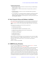
4.1 Where to Look for Answers .......................................................................................
Operation Manuals ............................................................................................
Installations ........................................................................................................
Technical References .........................................................................................
01-999186-00 B0902
MERCURYplus Console Acceptance Tests & Specifications
39
40
40
41
3
Table of Contents
4.2
4.3
4.4
4.5
4.6
Host Computer Setup and Software Installation ........................................................
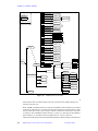
VNMR Directory Structure ........................................................................................
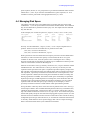
Managing Disk Space ................................................................................................
Tuning Probes ............................................................................................................
Data Acquisition – Calibration and Indanone Spectra ...............................................
The Calibration Process .....................................................................................
2-Ethyl-1-Indanone Spectra ...............................................................................
4.7 Magnet Maintenance ..................................................................................................
Periodic checks ..................................................................................................
Filling Cryogens ................................................................................................
4.8 30-Day System Maintenance .....................................................................................
4.9 Warranty and Who to Call for Assistance ..................................................................
41
41
43
44
44
44
50
56
56
57
57
58
Chapter 5. Acceptance Test Results............................................................... 59
5.1
5.2
5.3
5.4
5.5
4
Computer Audit .........................................................................................................
Installation Customer Training Checklist ..................................................................
System Installation Checklist ..................................................................................
Supercon Shim Values ...............................................................................................
Console and Magnet Test Results ..............................................................................
MERCURYplus Console Acceptance Tests & Specifications
01-999186-00 B0902
61
63
65
67
69
List of Figures
Figure 1. 10-Gauss Warning Sign...................................................................................................
Figure 2. 5-Gauss Warning Sign.....................................................................................................
Figure 3. Magnet Area Danger Sign...............................................................................................
Figure 4. GLIDE Calibrate LOCK..................................................................................................
Figure 5. GLIDE Setup Window and Drop Down Experiment Menu............................................
Figure 6. Acquisition Setup Window .............................................................................................
Figure 7. Probe Administration from Setup EXP ...........................................................................
Figure 8. Experiment Selection Window for Gradient Experiments..............................................
Figure 9. Experiment Selection Window for Nongradient Experiments........................................
Figure 10. NOESY Acquisition Parameter Window ......................................................................
Figure 11. 1H and 1H Detected Experiment List ...........................................................................
Figure 12. Experiment Window for 13C and 13C Detected Experiments .....................................
Figure 13. 13C and 13C Detected Experiment List........................................................................
Figure 14. MERCURYplus Online Manual Menu...........................................................................
Figure 15. VNMR Directory Structure...........................................................................................
Figure 16. 1H Spectrum of 13C-Methyl Iodide...............................................................................
Figure 17. 1H pw Array ..................................................................................................................
Figure 18. 13C pwx Array ..............................................................................................................
Figure 19. Gradient Profile .............................................................................................................
Figure 20. Gradient Calibrations ....................................................................................................
Figure 21. Proton Coupled 13C Spectrum of 13C-Methyl Iodide ...................................................
Figure 22. 13C Observe pw Array of Proton Coupled Spectra .......................................................
Figure 23. Proton Decoupler dof Array ........................................................................................
Figure 24. Calibration of the Decoupler 90° Pulse Width, pp .......................................................
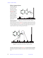
Figure 25. Proton Spectrum of 2-Ethyl-1-Indanone.......................................................................
Figure 26. Aliphatic Region of the 2-Ethyl-1-Indanone Spectrum ................................................
Figure 27. Aromatic Region of the 2-Ethyl-1-Indanone Spectrum ................................................
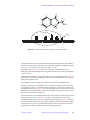
Figure 28. Gradient COSY of 2-Ethyl-1-Indanone ........................................................................
Figure 29. Gradient COSY (gCOSY) of Aliphatic Region of 2-Ethyl-1-Indanone .......................
Figure 30. Gradient COSY (gCOSY) of the Aromatic Region of 2-Ethyl-1-Indanone .................
Figure 31. TOCSY of 2-Ethyl-1-Indanone shows Correlations Among All Protons.....................
Figure 32. TOCSY of 2-Ethyl-1-Indanone, Correlations of Protons on C11, C10, C3..................
Figure 33. NOESY Spectrum of 2-Ethyl-1-Indanone ....................................................................
Figure 34. HSQC Spectrum of 2-Ethyl-1-Indanone.......................................................................
01-999186-00 B0902
MERCURYplus Console Acceptance Tests & Specifications
19
19
19
23
24
25
25
28
28
28
29
30
30
39
42
45
46
46
47
47
48
48
49
49
50
50
51
52
53
53
54
54
55
55
5
List of Tables
Table 1. Samples Required for Console Acceptance Tests ............................................................
Table 2. Samples for System Calibration ......................................................................................
Table 3. Sample for Automated Data Acquisition .........................................................................
Table 4. Samples for Homonuclear Decoupling Test ....................................................................
Table 5. Sample for Magnet Drift Test ..........................................................................................
Table 6. Samples for Optional VT Accuracy Test ........................................................................
Table 7. Samples for Optional High-Stability VT Test .................................................................
Table 8. Magnet Drift Specifications .............................................................................................
Table 9. Who to Call for Assistance ..............................................................................................
6
MERCURYplus Console Acceptance Tests & Specifications
01-999186-00 B0902
14
21
26
31
32
34
36
38
58
SAFETY PRECAUTIONS
The following warning and caution notices illustrate the style used in Varian manuals for
safety precaution notices and explain when each type is used:
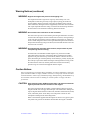
WARNING: Warnings are used when failure to observe instructions or precautions
could result in injury or death to humans or animals, or significant
property damage.
CAUTION:
Cautions are used when failure to observe instructions could result in
serious damage to equipment or loss of data.
Warning Notices
Observe the following precautions during installation, operation, maintenance, and repair
of the instrument. Failure to comply with these warnings, or with specific warnings
elsewhere in Varian manuals, violates safety standards of design, manufacturing, and
intended use of the instrument. Varian assumes no liability for customer failure to comply
with these precautions.
WARNING: Persons with implanted or attached medical devices such as
pacemakers and prosthetic parts must remain outside the 5-gauss
perimeter from the centerline of the magnet.
The superconducting magnet system generates strong magnetic fields that can
affect operation of some cardiac pacemakers or harm implanted or attached
devices such as prosthetic parts and metal blood vessel clips and clamps.
Pacemaker wearers should consult the user manual provided by the pacemaker
manufacturer or contact the pacemaker manufacturer to determine the effect on
a specific pacemaker. Pacemaker wearers should also always notify their
physician and discuss the health risks of being in proximity to magnetic fields.
Wearers of metal prosthetics and implants should contact their physician to
determine if a danger exists.
Refer to the manuals supplied with the magnet for the size of a typical 5-gauss
stray field. This gauss level should be checked after the magnet is installed.
WARNING: Keep metal objects outside the 10-gauss perimeter from the centerline
of the magnet.
The strong magnetic field surrounding the magnet attracts objects containing
steel, iron, or other ferromagnetic materials, which includes most ordinary
tools, electronic equipment, compressed gas cylinders, steel chairs, and steel
carts. Unless restrained, such objects can suddenly fly towards the magnet,
causing possible personal injury and extensive damage to the probe, dewar, and
superconducting solenoid. The greater the mass of the object, the more the
magnet attracts the object.
Only nonferromagnetic materials—plastics, aluminum, wood, nonmagnetic
stainless steel, etc.—should be used in the area around the magnet. If an object
is stuck to the magnet surface and cannot easily be removed by hand, contact
Varian service for assistance.
01-999186-00 B0902
MERCURYplus Console Acceptance Tests & Specifications
7
Warning Notices (continued)
Refer to the manuals supplied with the magnet for the size of a typical 10-gauss
stray field. This gauss level should be checked after the magnet is installed.
WARNING: Only qualified maintenance personnel shall remove equipment covers
or make internal adjustments.
Dangerous high voltages that can kill or injure exist inside the instrument.
Before working inside a cabinet, turn off the main system power switch located
on the back of the console, then disconnect the ac power cord.
WARNING: Do not substitute parts or modify the instrument.
Any unauthorized modification could injure personnel or damage equipment
and potentially terminate the warranty agreements and/or service contract.
Written authorization approved by a Varian, Inc. product manager is required to
implement any changes to the hardware of a Varian NMR spectrometer.
Maintain safety features by referring system service to a Varian service office.
WARNING: Do not operate in the presence of flammable gases or fumes.
Operation with flammable gases or fumes present creates the risk of injury or
death from toxic fumes, explosion, or fire.
WARNING: Leave area immediately in the event of a magnet quench.
If the magnet dewar should quench (sudden appearance of gasses from the top
of the dewar), leave the area immediately. Sudden release of helium or nitrogen
gases can rapidly displace oxygen in an enclosed space creating a possibility of
asphyxiation. Do not return until the oxygen level returns to normal.
WARNING: Avoid liquid helium or nitrogen contact with any part of the body.
In contact with the body, liquid helium and nitrogen can cause an injury similar
to a burn. Never place your head over the helium and nitrogen exit tubes on top
of the magnet. If liquid helium or nitrogen contacts the body, seek immediate
medical attention, especially if the skin is blistered or the eyes are affected.
WARNING: Do not look down the upper barrel.
Unless the probe is removed from the magnet, never look down the upper
barrel. You could be injured by the sample tube as it ejects pneumatically from
the probe.
WARNING: Do not exceed the boiling or freezing point of a sample during variable
temperature experiments.
A sample tube subjected to a change in temperature can build up excessive
pressure, which can break the sample tube glass and cause injury by flying glass
and toxic materials. To avoid this hazard, establish the freezing and boiling
point of a sample before doing a variable temperature experiment.
8
MERCURYplus Console Acceptance Tests & Specifications
01-999186-00 B0902
Warning Notices (continued)
WARNING: Support the magnet and prevent it from tipping over.
The magnet dewar has a high center of gravity and could tip over in an
earthquake or after being struck by a large object, injuring personnel and
causing sudden, dangerous release of nitrogen and helium gasses from the
dewar. Therefore, the magnet must be supported by at least one of two methods:
with ropes suspended from the ceiling or with the antivibration legs bolted to
the floor. Refer to the Installation Planning Manual for details.
WARNING: Do not remove the relief valves on the vent tubes.
The relief valves prevent air from entering the nitrogen and helium vent tubes.
Air that enters the magnet contains moisture that can freeze, causing blockage
of the vent tubes and possibly extensive damage to the magnet. It could also
cause a sudden dangerous release of nitrogen and helium gases from the dewar.
Except when transferring nitrogen or helium, be certain that the relief valves are
secured on the vent tubes.
WARNING: On magnets with removable quench tubes, keep the tubes in place
except during helium servicing.
On Varian 200- and 300-MHz 54-mm magnets only, the dewar includes
removable helium vent tubes. If the magnet dewar should quench (sudden
appearance of gases from the top of the dewar) and the vent tubes are not in
place, the helium gas would be partially vented sideways, possibly injuring the
skin and eyes of personnel beside the magnet. During helium servicing, when
the tubes must be removed, carefully follow the instructions and safety
precautions given in the manual supplied with the magnet.
Caution Notices
Observe the following precautions during installation, operation, maintenance, and repair
of the instrument. Failure to comply with these cautions, or with specific cautions elsewhere
in Varian manuals, violates safety standards of design, manufacturing, and intended use of
the instrument. Varian assumes no liability for customer failure to comply with these
precautions.
CAUTION:
Keep magnetic media, ATM and credit cards, and watches outside the
5-gauss perimeter from the centerline of the magnet.
The strong magnetic field surrounding a superconducting magnet can erase
magnetic media such as floppy disks and tapes. The field can also damage the
strip of magnetic media found on credit cards, automatic teller machine (ATM)
cards, and similar plastic cards. Many wrist and pocket watches are also
susceptible to damage from intense magnetism.
Refer to the manuals supplied with the magnet for the size of a typical 5-gauss
stray field. This gauss level should be checked after the magnet is installed.
01-999186-00 B0902
MERCURYplus Console Acceptance Tests & Specifications
9
Caution Notices (continued)
CAUTION:
Keep the PCs, (including the LC STAR workstation) beyond the 5gauss perimeter of the magnet.
Avoid equipment damage or data loss by keeping PCs (including the LC
workstation PC) well away from the magnet. Generally, keep the PC beyond the
5-gauss perimeter of the magnet. Refer to the Installation Planning Guide for
magnet field plots.
CAUTION:
Check helium and nitrogen gas flowmeters daily.
Record the readings to establish the operating level. The readings will vary
somewhat because of changes in barometric pressure from weather fronts. If
the readings for either gas should change abruptly, contact qualified
maintenance personnel. Failure to correct the cause of abnormal readings could
result in extensive equipment damage.
CAUTION:
Never operate solids high-power amplifiers with liquids probes.
On systems with solids high-power amplifiers, never operate the amplifiers
with a liquids probe. The high power available from these amplifiers will
destroy liquids probes. Use the appropriate high-power probe with the highpower amplifier.
CAUTION:
Take electrostatic discharge (ESD) precautions to avoid damage to
sensitive electronic components.
Wear a grounded antistatic wristband or equivalent before touching any parts
inside the doors and covers of the spectrometer system. Also, take ESD
precautions when working near the exposed cable connectors on the back of the
console.
Radio-Frequency Emission Regulations
The covers on the instrument form a barrier to radio-frequency (rf) energy. Removing any
of the covers or modifying the instrument may lead to increased susceptibility to rf
interference within the instrument and may increase the rf energy transmitted by the
instrument in violation of regulations covering rf emissions. It is the operator’s
responsibility to maintain the instrument in a condition that does not violate rf emission
requirements.
10
MERCURYplus Console Acceptance Tests & Specifications
01-999186-00 B0902
Chapter 1.
Introduction
Sections in this chapter:
•
•
•
•
•
•
1.1 “Overview of the Acceptance Testing Process” this page
1.2 “General Acceptance Testing Requirements” page 14
1.3 “Samples Required for Acceptance Tests” page 14
1.4 “General Testing and Specification Requirements” page 14
1.5 “Varian Sales Offices” page 17
1.6 “Posting Requirements for Magnetic Field Warning Signs” page 18
Following each installation of a Varian, Inc. MERCURYplus NMR spectrometer system, an
installation engineer tests and demonstrates the instrument’s operation using the procedures
in this manual.
This manual contains the acceptance test procedures and specifications for MERCURYplus
NMR spectrometers. The following is an overview of the chapters in this manual:
•
Chapter 2, “Console and Magnet Test Procedures,” provides the acceptance test
procedures.
•
Chapter 3, “Consoles and Magnets Specifications,” provides the acceptance test
specifications.
•
Chapter 4, “Customer Training,” provides basic spectrometer maintenance and
operation training.
•
Chapter 5, “Acceptance Test Results,” contains forms for recording test results.
The acceptance test procedures and specifications for each probe are contained in a separate
probe family manual, for example procedures and specifications for AutoSwitchable probes
are contained in the AutoSwitchable NMR Probes manual.
Only the lineshape and signal to noise tests are preformed manually. All other probe
calibrations are performed by the instrument during the auto calibration procedures. The
manual tests are provided as a reference.
1.1 Overview of the Acceptance Testing Process
The objectives of the acceptance tests procedures are threefold:
•
•
•
To identify the tests to be performed during system installation.
To identify the precise methods by which these tests are performed.
To leave the instrument in a calibrated, ready to use, state.
01-999186-00 B0902
MERCURYplus Console Acceptance Tests & Specifications
11
Chapter 1. Introduction
Acceptance Tests
Acceptance test procedures are arranged by the type of specification. These procedures
cover the basic specifications of the instrument—signal-to-noise, resolution, and
lineshape—and are not intended to reflect the full range of operating capabilities or features
of a MERCURYplus NMR spectrometer. The order in which the tests are performed is
determined by the installation engineer, although the order does not matter except that some
procedures use results from other procedures
Performance of additional tests beyond those described in this manual must be agreed upon
in writing as part of the customer contract.
Acceptance Specifications
All specifications are subject to change without notice. The specifications published in this
manual shall prevail unless negotiation or customer contract determines otherwise. Refer
to the text in each chapter for other conditions.
Request for additional specifications beyond those listed in this manual must be agreed
upon in writing as part of the customer contract. The following policies are in effect at
installation:
•
Specifications Policy for Probes Used in Systems other than MERCURYplus – No
guarantee is given that probes purchased for use in systems other than MERCURYplus
will meet current specifications.
•
Testing Policy for Indirect Detection Probes used for Direct Observe Broadband
Performance – Probes designed for indirect detection applications are tested for
indirect detection performance only. Indirect detection acceptance tests are performed
only if an indirect detection probe was purchased for use with the MERCURYplus.
•
Sample Tubes Policy – Tests are performed in 5-mm sample tubes with 0.38 mm wall
thickness (Wilmad 528-PP, or equivalent) and 10-mm sample tubes with 0.46 mm wall
thickness (Wilmad 513-7PP, or equivalent). Using sample tubes with thinner walls
(Wilmad 5-mm 545-PPT, or equivalent; Wilmad 10-mm 513-7PPT, or equivalent)
increases signal-to-noise.
Computer Audit
A computer audit form is included in “Computer Audit,” page 61. The information from
this form will help Varian assist you better in distributing future software upgrades and
avoiding hardware compatibility problems. You are asked for information about all
computers directly connected to the spectrometer or else used to process NMR data.
Installation Checklist
An installation checklist form is included in “System Installation Checklist,” page 65.
System Documentation Review
Following the completion of the acceptance tests and computer audit, the installation
engineer will review the following system documentation with the customer:
•
•
•
12
Software Object Code License Agreement.
Varian and OEM manuals.
Warranty coverage and where to telephone for information.
MERCURYplus Console Acceptance Tests & Specifications
01-999186-00 B0902
1.1 Overview of the Acceptance Testing Process
Basic System Demonstration
The installation engineer will also demonstrate the basic operation of the system to the
laboratory staff. The objective of the demonstration is to familiarize the customer with
system features and safety requirements, as well as to assure that all mechanical and
electrical functions are operating properly.
The system demonstration includes the following items:
Magnet Demonstration
The following are demonstrated:
•
•
•
•
•
Posting requirements for magnetic field warning signs.
Cryogenics handling procedures and safety precautions.
Magnet refilling.
Flowmeters.
Homogeneity disturbances.
Console and Probe Demonstration
The following are demonstrated:
•
•
•
Loading programs (VNMR, Optional VNMR packages, Solaris).
•
Auto calibration, using the GLIDE or Tcl-dg interface, of key probe parameters such
as 1H pw90, 13C pwx90, decoupler field, gradient strength (if gradients are present),
and other probe specific parameters.
•
Demonstration of automated data acquisition via GLIDE interface. Using the 2-Ethyl1-indanone sample provided with the console the following experiments will be run:
Experiment setup, including installing the probe in the magnet.
Basic instrument operation to obtain typical spectra, including probe tuning, magnet
homogeneity shimming, and printer/plotter operation. (Note that Varian installation
engineers are not responsible for, or trained to, run any spectra not described in this
manual.)
• 1D Experiments: 1H, 13C{1H}, APT and DEPT.
• 2D Non gradient experiments: NOESY and TOCSY (for non-gradient system
or probe COSY is also run).
• 2D Gradient experiments: gCOSY, gHSQC, gHMBC will be demonstrated if
gradients are present.
•
Walk through the demonstration spectra and the “Data Acquisition – Calibration and
Indanone Spectra,” page 44.
•
•
•
Demonstration of gradient shimming using PFG gradients, if present, or homospoil.
Review how to use the manuals (online and hard copy) and where to find information.
Review the post installation 30 day check list.
Detailed specifications and circuit descriptions are not covered.
Formal training in the operation and maintenance of the spectrometer is conducted by
Varian at periodically scheduled training seminars held in most Varian Application
Laboratories. Installation engineers are responsible for guiding you through the acquisition
of the spectra as provided in the manual. The installation engineer is not responsible for
interpretation of the results beyond what is provided in this manual. On-site training is
01-999186-00 B0902
MERCURYplus Console Acceptance Tests & Specifications
13
Chapter 1. Introduction
available in some geographic locations. Contact your sales representative for further
information on availability and pricing for these courses.
To make the system demonstration most beneficial, the customer should review Varian and
OEM manuals before viewing the demonstration.
1.2 General Acceptance Testing Requirements
Each MERCURYplus spectrometer is designed to provide high-resolution performance
when operated in an environment as specified in the Installation Planning Guide. Unless
both the specific requirements of this manual and the general requirements specified in the
MERCURYplus Installation Planning Guide are met, Varian cannot warrant that the NMR
spectrometer system will meet the published specifications.
1.3 Samples Required for Acceptance Tests
The MERCURYplus spectrometer is supplied with the samples listed in Table 1
Table 1. Samples Required for Console Acceptance Tests
Test Sample
Sample Tube
Nucleus
(mm)
Sample
Part Number
13C
enriched 1% methyl iodide, 1% Trimethyl
phosphite, and 0.2% Cr(AcAc) in Chloroform-d
5
13C
00-968120-96
Doped 2-Hz H2O/D 2O (0.1 mg/ml GdCl3 in
5
1
H
01-901855-01
2% 2-ethyl-1-indanone in Chloroform-d
5
1
H and 13C
01-901855-03
0.1% ethylbenzene, 0.01% TMS,
99.89% deuterochloroform (CDCl3)
5
00-968120-70
0.1% ethylbenzene, 0.01% TMS,
99.89% deuterochloroform (CDCl3)
10
00-968123-70
chloroform in acetone-d6 lineshape
5
00-968120-xx
100% methanol (reagent grade) –50 to +25 (Low)
5
00-968120-80
100% ethylene glycol (reagent grade) +25 to +100
(High)
5
00-968120-79
1% H2O in D2O)
The samples required for acceptance testing of any individual probe are supplied with the
probe. Typical samples required for probe acceptance tests are: chloroform in acetone-d6,
ethyl benzene in chloroform-d, and ASTM (40% p-dioxane in 60% benzene-d6). Other
samples might be required depending upon the type of probe. The specific sample
requirements and test procedures are specified in the manual for each probe.
1.4 General Testing and Specification Requirements
• The MERCURYplus performance specifications in effect at the time of your order are
used to evaluate the system.
•
14
The appropriate quarter-wavelength cable must be used for each nucleus except
autoswitchable probes operated in 4-nucleus mode. The 13C quarter-wavelength cable
is used in this case.
MERCURYplus Console Acceptance Tests & Specifications
01-999186-00 B0902
1.4 General Testing and Specification Requirements
•
Homogeneity settings must be optimized for each sample (manual shimming may be
required in any or all cases). The shim parameters for resolution tests on each probe
should be recorded in a log book and in a separate file name (in the directory /vnmr/
shims) for each probe. For example, for a 5-mm switchable probe, the shim
parameters can be saved with the command svs('sw5res'). These values can then
be used as a starting point when adjusting the homogeneity on unknown samples, by
the command rts('sw5res').
•
•
The probe must be tuned to the appropriate frequency.
Spinning speed must be set to the following:
Sample (mm)
Nuclei
Speed (Hz)
5
all
20–26
10
all
15
Spinning 10-mm tubes faster than 15 Hz can cause vortexing in samples, severely
degrading the resolution.
•
Some test parameters are stored in the disk library /vnmr/tests and can be recalled
by entering rtp('/vnmr/tests/xxx'), where xxx is the name of the file that
contains the parameters to be retrieved—e.g., rtp('/vnmr/tests/H1sn'). To
see the parameter sets available for the standard tests, enter ls('/vnmr/tests').
Other sets come from /vnmr/stdpar.
•
Many of the probe parameters and performance specifications will be determined
automatically and the corresponding manual tests will NOT be run by the installer.
Certain tests, such as signal to noise and lineshape will be run manually. Tests
corresponding to the automatic performance tests are provided should you want to run
them at a later time.
•
For all sensitivity tests, the value of pw must be changed to the value of the 90° pulse
found in the pulse width test on the same probe and nucleus.
•
During calibration, GLIDE creates an appropriate pw array to determine the 90° pulse
width. For manually run observe pulse width tests, an appropriate array of pw values
must be entered to determine the 360° pulse. The 360° pulse is the first non-zero pulse
that gives minimum intensity of the spectrum. The 360° pulse is usually determined by
interpolation between a value that gives a positive signal, and a value that gives a
negative signal. The 90° pulse width is one quarter the 360° pulse (360/4).
•
Signal-to-noise (S/N) is measured by the computer as follows:
maximum amplitude of peak
S/N =
2 x root mean square of noise region
•
Lineshape should be measured digitally with the aid of the system software. The
properly scaled spectra should also be plotted and the plot retained.
•
Digital determination of lineshape:
1.
Display and expand the desired peak.
2.
Enter nm, then dc for drift correction to ensure a flat baseline. Set
vs=10000. Click the menu button labeled Th to display the horizontal
threshold cursor. Set th=55 (the 0.55% level).
3.
Click the menu button labeled Cursor or Box until two vertical cursors are
displayed, and align them on the intersections of the horizontal cursor and the
peak. Enter delta? to see the difference in Hz between the cursors.
01-999186-00 B0902
MERCURYplus Console Acceptance Tests & Specifications
15
Chapter 1. Introduction
•
4.
Set th=11 (the 0.11% level) and repeat.
5.
You can also use the macro res. Place the cursor on the resonance of interest
and type res on the command line.
Determination of lineshape from a plot:
1.
Use a large enough plot width to allow accurate determination of the baseline.
The baseline should be drawn through the center of the noise, in a region of
the spectrum with no peaks.
2.
The 0.55% and 0.11% levels are then measured from the baseline and
calculated from the height of the peak and the value of vs. For example, if a
peak is 9.0 cm high with vs=200, then the 0.55% level on a 100-fold vertical
expansion (vs=20000) is 9 × 0.55 , or 4.95 cm from the baseline.
If the noise is significant at the 0.55% and 0.11% levels, the linewidth should be
measured horizontally to the center of the noise.
16
•
Use the dsnmax macro to determine signal-to-noise (sensitivity). You can also choose
a noise region free of any anomalous features with the cursors. Neither cursor should
be placed any closer to an edge of the spectrum than 10 percent of the value of sw. This
should produce the best possible signal-to-noise that is representative of the spectrum.
•
The results of all tests should be plotted to create a permanent record. Include a
descriptive label and a list of parameters. These plots can then be saved as part of the
acceptance tests documentation.
MERCURYplus Console Acceptance Tests & Specifications
01-999186-00 B0902
1.5 Varian Sales Offices
1.5 Varian Sales Offices
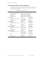
For product sales and service information, contact one of the Varian sales offices:
•
•
•
•
•
•
•
•
•
•
•
•
•
•
•
•
•
•
•
•
•
•
•
Argentina, Buenos Aires, (114) 783-5306
•
Venezuela, Valencia (41) 257608
Australia, Mulgrave, Victoria, (3) 9566-1138
Austria, Vösendorf, (1) 699 96 69
Belgium, Brussels, (02) 721 51 51
Brazil, Sao Paulo, (11) 829-5444
Canada, Ottawa, Ontario, (613) 260-0331
China, Beijing, (10) 6846-3640
Denmark, Herlev, (42) 84 6166
France, Orsay, (1) 69 86 38 38
Germany, Darmstadt, (6151) 70 30
Italy, Milan, (2) 921351
Japan, Tokyo, (3) 5232 1211
Korea, Seoul, (2) 3452-2452
Mexico, Mexico City, (5) 523-9465
Netherlands, Houten, (0118) 61 71 56
Norway, Oslo, (9) 86 74 70
Russian Federation, Moscow, (95) 241-7014
Spain, Madrid, (91) 472-7612
Sweden, Solna, (8) 445 1601
Switzerland, Zug, (41) 749 88 44
Taiwan, Taipei, (2) 2698-9555
United Kingdom, Walton-on-Thames, England (1932) 898 000
United States, Palo Alto, California,
Varian, Inc., NMR Systems
Customer Sales Support, (650) 424-5434
Service Support, Palo Alto, California, 1 (800) 356-4437
E- mail: [email protected]
North American Service Manager
9017 Mendenhall Ct., Ste D, Columbia, MD 21045
(410) 381-7229
01-999186-00 B0902
MERCURYplus Console Acceptance Tests & Specifications
17
Chapter 1. Introduction
1.6 Posting Requirements for Magnetic Field Warning Signs
The strong magnetic fields that surround a superconducting magnet are capable of causing
death or serious injury to individuals with implanted or attached medical devices such as
pacemakers or prosthetic parts. Such fields can also suddenly pull nearby magnetic tools,
equipment, and dewars into the magnet body with considerable force, which could cause
personal injury or serious damage. Moreover, strong magnetic fields can erase magnetic
media such as tapes and floppy disks, disable the information stored on the magnetic strip
of automated teller machine (ATM) and credit cards, and damage some watches.
To warn of the presence and hazard of strong magnetic fields, the customer is responsible
for posting clearly visible signs warning of magnetic field hazards. This responsibility
includes measuring stray fields with a gaussmeter.
Radio-frequency emissions may also pose a danger to some individuals. The rf emission
levels from Varian NMR equipment have been measured and compared to the IEEE/ANSI
C95.1-1991 standard. For further information, refer to the RF Environment section of the
Installation Planning Guide.
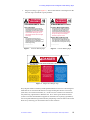
Warning Signs
Varian provides signs to help customers meet this posting responsibility. These signs must
be posted according to the following requirements before the magnet is energized:
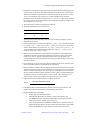
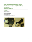
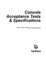
1.
10-gauss warning signs (Figure 1) – Post along the 10-gauss perimeter of the magnet
so that a sign can be easily seen by any person about to enter the 10-gauss field from
any direction. Refer to the manuals supplied with the magnet for the size of a typical
10-gauss stray field. Check this gauss level after the magnet is installed.
Note that the stray field may extend vertically to adjacent floors, and additional signs
may be needed there. A sign is not required if the 10-gauss field extends less than 30
cm (12 in.) beyond a permanent wall or less than 61 cm (24 in.) beyond the floor
above the magnet.
2.
18
5-gauss warning signs (Figure 2) – Post along the 5-gauss perimeter of the magnet
so that a sign can be easily seen by any person about to enter the 5-gauss field from
any direction. Refer to the manuals supplied with the magnet for the size of a typical
5-gauss stray field. Check this gauss level after the magnet is installed. Note that the
stray field may extend vertically to adjacent floors, and additional signs may be
needed there.
MERCURYplus Console Acceptance Tests & Specifications
01-999186-00 B0902
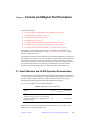
1.6 Posting Requirements for Magnetic Field Warning Signs
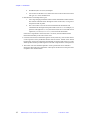
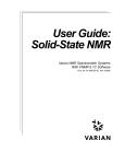
3.
Magnet area danger signs (Figure 3) – Post at each entrance to the magnet area. Be
sure each sign is outside the 5-gauss perimeter.
10-GAUSS
WARNING
5-GAUSS
WARNING
STRONG MAGNETIC FIELD
STRONG MAGNETIC FIELD
Tools and Equipment
Pacemaker, Metallic Implant Hazard
Strong magnetic fields are present that can
make magnetic items suddenly fly towards the
magnet, which could cause personal injury or
serious damage. Do not take tools, equipment,
or personal items containing steel, iron, or
other magnetic materials closer to the magnet
than this sign.
Dewars
Strong magnetic and rf fields are present that
can cause serious injury or death to persons
with implanted or attached medical devices,
such as pacemakers and prosthetic parts. Such
persons must not go closer to the magnet than
this sign until safety at a closer distance is
identified by a physician or device
Magnetic Media, ATM/Credit Cards
The stray field of the magnet can pull a
magnetic dewar into the magnet body, causing
serious damage. Use only nonmagnetic
stainless steel dewars. Do not use iron or steel
dewars during servicing.
Strong magnetic fields are present that can
erase magnetic media, disable ATM and credit
cards, and damage some watches. Do not take
such objects closer to the magnet than this sign.
Pub. No. 87-250303-00 B0694 5-Gauss Warning Sign
Pub. No. 87-250302-00 B0694 10-Gauss Warning Sign
Figure 1. 10-Gauss Warning Sign
Figure 2. 5-Gauss Warning Sign
DANGER
STRONG MAGNETIC AND RADIO-FREQUENCY FIELDS ARE PRESENT
Pacemaker and
Metallic Implant Hazard
Magnetic Media and
ATM/Credit Cards
Tools and Equipment
Strong magnetic and radiofrequency fields are present that
could cause serious injury or
death to persons with implanted
or attached medical devices,
such as pacemakers and
prosthetic parts.
Strong magnetic fields are
present that could erase
magnetic media such as
floppies and tapes, disable ATM
and credit cards, and damage
some watches.
Strong magnetic fields are
present that could make some
magnetic items suddenly fly
towards the magnet body, which
could cause personal injury or
serious damage.
Do not take such objects closer
to the magnet than the
5-GAUSS WARNING signs.
Do not take tools, equipment,
or personal items containing
steel, iron, or other magnetic
materials closer to the
magnet than the
10-GAUSS WARNING signs.
Such persons must not go
closer to the magnet than the
5-GAUSS WARNING signs until
safety at a closer distance is
identified by a physician or
medical device manufacturer.
Pub. No. 87-250301-00 B0694
Magnet Area Entrance Danger Sign
Figure 3. Magnet Area Danger Sign
Stray magnetic fields can reach beyond the published distances when two or more magnetic
fields intersect or when the field extends over large ferromagnetic masses or structures
(steel doors, steel construction beams, etc.). In this case, the customer must measure the
stray field using a gaussmeter to determine how the 5- and 10-gauss fields are altered
(contact a scientific instrumentation supplier for information on acquiring a gaussmeter).
You can request additional signs from Varian by telephoning 1-800-356-4437 in the United
States or by contacting your local Varian office in other countries.
01-999186-00 B0902
MERCURYplus Console Acceptance Tests & Specifications
19
Chapter 1. Introduction
20
MERCURYplus Console Acceptance Tests & Specifications
01-999186-00 B0902
Chapter 2.
Console and Magnet Test Procedures
Sections in this chapter:
•
•
•
•
•
•
•
2.1 “AutoCalibration and GLIDE Operation Demonstration” page 21
2.2 “Automated Data Acquisition” page 26
2.3 “Homonuclear Decoupling” page 31
2.4 “Magnet Drift Test” page 32
2.5 “Variable Temperature Operation (Optional Hardware)” page 33
2.6 “Temperature Accuracy for VT Systems (Optional Test)” page 34
2.7 “Stability Calibration for High-Stability VT (Optional Test)” page 36
This chapter contains the procedures required to demonstrate the specifications for
MERCURYplus consoles and magnets. Chapter 5, “Acceptance Test Results,” contains
forms for writing the results.
Lineshape and resolution tests described in the probe manual shipped with your probe must
be run before these console tests are run. During the console tests probe calibration files are
created that are used during some of the console tests. The probe calibrations written to
these probe files will meet or exceed the specifications for the probe. Probe performance
tests and calibrations that are executed during AutoCalibration will not be repeated
manually. These probe calibration files are required for some of the console tests.
2.1 AutoCalibration and GLIDE Operation Demonstration
The AutoCalibration procedures calibrates the probe and demonstrates the performance of
the probe. During the AutoCalibration, a probe calibration file containing the 1H and 13C
90° pulse widths, decoupler calibration, gradient calibration (if present) is set up as
described in the probe installation manual that shipped with your probe.
Table 2 lists the samples used for the AutoCalibration.
Table 2. Samples for System Calibration
Sample
Nucleus
Sample
Part Number
Tube (mm)
13
C enriched 1% methyl iodide, 1% trimethyl
phosphite, and 0.2% Cr(AcAc) in Chloroform-d
13
5
00-968120-96
Doped 2-Hz H2O/D2O (0.1 mg/ml GdCl3 in
1
5
01-901855-01
C
H
1% H2O in D2O)
The total time for the tests and calibrations should be about 1 hour. Run the tests and
calibrations in the following general order:
01-999186-00 B0902
MERCURYplus Console Acceptance Tests & Specifications
21
Chapter 2. Console and Magnet Test Procedures
•
•
•
Run the lineshape tests described in the probe manual before running AutoCalibration.
Run the AutoCalibration as described in this section.
Run the signal-to-noise test described in the probe manual. Use the pw90 determined
by the AutoCalibration routine.
Setting Up Probe Calibration Files
Before you calibrate a probe for the first time, you must set up the probe calibration file with
the addprobe command as described below.
1.
Log in as vnmr1.
2.
Enter one of the following command:
addprobe(probe_name)
The probe calibrations are written to the probe file in ~/vnmr1/vnmrsys/
probe/probe_name and are available only to the user vnmr1.
– OR –
addprobe(probe_name,'system')
The calibrations are written to /vnmr/probe/probe_name and are available
to all users.
Some probes, like the Autoswitchable and 4 nucleus probes, require additional calibrations
not covered in this manual. For information on using GLIDE to compleat the calibration of
these probes, see the Walkup NMR manual and installation, testing, and specifications
manual the Probe.
Calibrating Z0 and Make LOCK gmap
Before preceding any further, the lock and gradients must be calibrated for the autoshim
and autolock procedures to function efficiently. This procedure calibrates Z0 and makes a
gradient map for gradient shimming.
22
1.
Insert the doped 2-Hz D2O sample (see Table 2).
2.
Open the acqi window by pressing the acqi button on the VNMR menu. Lock
onto the D2O resonance. The lock must be set on-resonance. Adjust Z0 as necessary.
3.
Adjust Lock Gain and Lock Power and set the lock level at 80%.
4.
Exit acqi.
5.
Open GLIDE by clicking on the GLIDE button in the VNMR menu and click the
Setup icon in GLIDE.
MERCURYplus Console Acceptance Tests & Specifications
01-999186-00 B0902
2.1 AutoCalibration and GLIDE Operation Demonstration
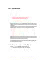
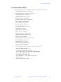
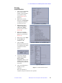
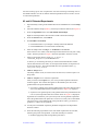
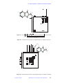
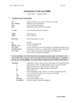
Running
AutoCalibration
1.
Click on the GLIDE Setup
button in the GLIDE
interface. The Experiment
and Calibration Setup
window (Figure 4A) is
displayed.
2.
Right mouse click the
button next to Experiment
to display the experiment
and calibration menu.
3.
Right mouse click on
“Generate lk gmap &
calibrate z0 “(D2O)”
selection from the menu
(Figure 4B).
4.
Right mouse click the
button next to Solvent to
display the solvent menu
(Figure 4C).
5.
Right mouse click on D2O.
6.
Set Autoshim and
Autolock to NO
7.
Click on Setup.
(A) Experiment Setup Window
(B) Select Calibration from Experiment Menu
Standard proton parameters
are recalled and the sample
confirmation window
appears.
8.
The message “Set z0
exactly on-resonance
before starting
acquisition” displays in the
VNMR window. Open the
lock display and set the lock
as directed
9.
Click on the GO button in
GLIDE to run the
calibration.
(C) Solvent Menu
Figure 4. GLIDE Calibrate LOCK
When the calibration is
completed, the probe calibration file is updated.
01-999186-00 B0902
MERCURYplus Console Acceptance Tests & Specifications
23
Chapter 2. Console and Magnet Test Procedures
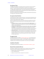
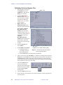
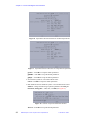
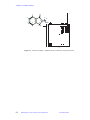
Calibrating Probe and System Files
1.
Open GLIDE by clicking on
the GLIDE button in the
VNMR menu, and click the
Setup icon in GLIDE.
2.
Use the Sample: Eject /
Insert buttons (Figure 5) to
eject the 2-Hz D 2O sample
and insert the chloroform
sample (Table 2). Tune the
probe if needed.
3.
Right - click on the
Experiment select button
using the right mouse button.
Right - click
Left - click on Calibrate
H,C,Ind.Det.&Grad.
(CH3I) in the drop down
experiment menu, (see Figure
5) (place the mouse pointer on
the experiment selection
Calibrate
H,C,Ind.Det.&Grad.
(CH3I) and click with the left
mouse button). Make this
selection for pfg and non pfg
systems.
4.
From the Solvent menu,
select CDCl3.
5.
Set Autoshim and Autolock.
• Click the No button if
your sample is already
locked and shimmed.
Left - click
Calibrate H, C, Ind.Det. & Grad. (CH3I)
Figure 5. GLIDE Setup Window and Drop
Down Experiment Menu
• Click the YES button to lock and shim automatically.
6.
Enter a relevant text in the Text field (e.g., calibration of ASWprobe) and click the
Setup button. If the text box is not visible, place the mouse pointer on the bottom of
the Setup Window boarder. The mouse pointer will change to an arrow pointing
down to a short bar. Press and hold the left mouse button and drag the bottom boarder
down until the text entry box is full visible.
7.
Click the Confirm button.
At the end of the setup
operation, the Custom and Go
buttons are no longer shaded
and the GLIDE Acquire
button appears.
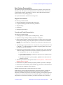
24
8.
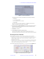
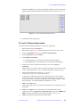
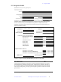
Click the Acquire button to open the Acquisition Setup window, see Figure 6.
9.
For the purposes of the ATP/ATS, select all the calibration routines appropriate for
the current probe.
MERCURYplus Console Acceptance Tests & Specifications
01-999186-00 B0902
2.1 AutoCalibration and GLIDE Operation Demonstration
Figure 6. Acquisition Setup Window
No matter what order you select, the calibration order is always the following:
• H1 observe
• C13 decouple, gradient
• H1-C13 gradient ratio, C13 observe
• H1 decouple
If you do not select one of these calibrations, it is skipped. If you do not have
gradients, the gradient related calibrations are skipped.
10. Enter the H1 and C13 pulse specifications of your probe’s for H1 and C13 observe
pw90 and decoupler pulses. If you do not enter a value, the calibration routine
defaults to 15 usec for all pulses.
11. Plot Results - select Yes.
12. Click the Do button to start the calibration routine.
At the end of the calibration routine, the power and pulse width values are
automatically incorporated into the probe file and the calibration spectra are plotted.
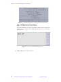
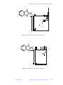
Reviewing the Probe Calibration
Probe calibrations executed by vnmr1 are written to probe files one of two places.
•
If the probe was created as a system probe and the probe name is unique (it does not
exist in /export/home/vnmr1/vnmrsys/probe) it is written to /vnmr/
probes/probe_name.
•
If the probe was not created as a system probe or the probe name is not unique (it does
exist in /export/home/vnmr1/vnmrsys/probe) it is written to /export/
home/vnmr1/vnmrsys/probes/probe_name.
You can read or edit the file with a text editor (e.g., vi) or you can use the setup EXP pane.
Figure 7. Probe Administration from Setup EXP
01-999186-00 B0902
MERCURYplus Console Acceptance Tests & Specifications
25
Chapter 2. Console and Magnet Test Procedures
1.
Log in as vnmr1 and start VNMR.
2.
Click on the Setup EXP tab.
3.
In the Probe Administration part of the Setup EXP pane, select the probe
calibration you want to edit (see Figure 7).
4.
Click on a field to review data.
The current values are shown in parentheses next
to the probe parameter. To change a parameter
value, enter the new value in the blank
If you are a user other then vnmr1, the system
probe calibrations are displayed in the TEXT
pane. The calibrations cannot be changed.
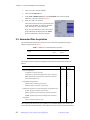
2.2 Automated Data Acquisition
The automated data acquisition consists of several 1D and 2D experiments using the
indanone sample listed in Table 3.
Table 3. Sample for Automated Data Acquisition
Sample
Sample Size Sample Part
(mm)
Number
2% 2-ethyl-1-indanone in chloroform-d
5
01-901855-03
The system (console and probe) configuration determines the experiment selection as
follows:
Tests
Gradient
Systems
Nongradient
Systems
Acquisition of a proton spectrum
✔
✔
Acquisition of a proton decoupled carbon observe spectrum
✔
✔
DEPT (distortionless enhancement by polarization transfer)
✔
✔
APT (attached proton test)
✔
✔
TOCSY (total correlation spectroscopY)
✔
✔
NOESY (nuclear overhauser spectroscopY)
✔
✔
Four 1 D experiments:
Nongradient 2D experiments:
Gradient 2D experiments (requires PFG option and gradient probe)
gCOSY (gradient correlation spectroscopY)
✔
gHSQC (gradient heteronuclear single quantum correlation
✔
gHMBC (gradient heteronuclear multiple bond correlation)
✔
Nongradient
COSY (correlation spectroscopY)
✔
These experiments demonstrate the capabilities of the MERCURYplus spectrometer, the
correct calibration of the instrument, and validate the correct functioning of the instrument.
26
MERCURYplus Console Acceptance Tests & Specifications
01-999186-00 B0902
2.2 Automated Data Acquisition
You will be setting up two sets of experiments. You will be clicking on the Setup icon on
the GLIDE interface once for H1 and H1 detected experiments and once of the C13 and
C13 detected experiments.
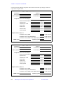
H1 and H1 Detected Experiments
1.
Open GLIDE by clicking on the GLIDE button in the VNMR menu. Click the Setup
icon.
2.
Insert the indanone sample (Table 3); use the Eject and Insert buttons (see Figure 5).
3.
From the Experiment menu, select H1 and H1 detected Expt.
Right-click the Experiment menu and left click H1 and H1 detected Expt.
4.
From the Solvent menu, select CDCl3.
5.
Set Autoshim and Autolock.
• Click the No button if your sample is already locked and shimmed.
• Click the YES button to lock and shim automatically.
6.
Enter the sample name 2-ethyl-1-indanone in the text box.
If the Text box is not visible, resize the Setup window until the text entry box is fully
visible. The Setup window in Figure 5 has been expanded to show the text box.
7.
Enter an appropriate directory name (e.g., 2-ethyl-1indanone_H1spectra) on the Save As: line.
A directory is created using the name you entered on the Save As line with the
current date and time to the name. As each experiment finishes, the experiment is
saved in this directory. The individual FIDs have the experiment names, e.g.
cosy.fid, tocsy.fid, etc.
8.
Click the Setup button.
The Setup window closes, the Custom icons become active, and the Acquire icon
drops down.
9.
Click the Acquire icon to select the experiments.
After you click on the Acquire icon, one of two possible Experiment Selection
windows appears. The window that appears is determined by the value of the
gradient field in the probe definition file.
• If you have a gradient probe (and the gradient field in the probe definition file is
set to Y) the Experiment Selection window shown in Figure 8 is displayed.
• If you have a non-gradient probe (or the gradient field in the probe definition file
is set to N) the Experiment Selection window shown in Figure 9 is displayed.
If gradients are installed on your system and you do not see gradient experiments
listed, the gradient field in the probe file is incorrect or an entry has not been made.
The correct entry in the gradient field of the probe file is either y (yes there are
gradients) or n (there are no gradients).
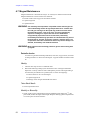
10. Use the proton 1D default acquisition parameters displayed in the Experiment
Selection window.
11. Select the following experiments in the order listed. Experiments are executed,
following the proton 1D experiment, in the order that they are selected.
• Gradient-equipped systems with gradient probe select:
01-999186-00 B0902
MERCURYplus Console Acceptance Tests & Specifications
27
Chapter 2. Console and Magnet Test Procedures
Figure 8. Experiment Selection Window for Gradient Experiments
Figure 9. Experiment Selection Window for Nongradient Experiments
gCOSY – click OK to accept the default parameters.
gHMBC – click OK to accept the default parameters.
gHSQC – click OK to accept the default parameters.
• Non Gradient systems or non-Gradient Probe select:
COSY– click OK to accept the default parameters.
• Both Gradient and Non-Gradient systems or non-Gradient Probe select:
NOESY – Change the following acquisition parameters: 4 Scans per
increment, mixing time = 1 sec; then, click OK (see Figure 10).
Figure 10. NOESY Acquisition Parameter Window
TOCSY – click OK to accept the default parameters.
28
MERCURYplus Console Acceptance Tests & Specifications
01-999186-00 B0902
2.2 Automated Data Acquisition
Each time the OK button is clicked an experiment is added to the list of experiments
displayed in the VNMR TEXT pane in the order they are run, as shown in Figure 11.
Figure 11. 1H and 1H Detected Experiment List
12. Click Do to start data acquisition.
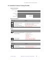
C13 and C13 Detected Experiments
All systems and broadband-capable probes can run these experiments.
1.
Open GLIDE and click the Setup icon.
The indanone sample (Table 3) should already be inserted. If not, insert it now.
2.
From the Experiment menu, select C13 and C13 detected Expt.
3.
From the Solvent menu, select CDCl3.
4.
Set Autoshim and Autolock.
• Click the No button if your sample is already locked and shimmed.
• Click the YES button if you would prefer to lock and shim automatically.
5.
In the Text box, enter the name of the sample, in this case 2-ethyl-1indanone.
If the Text box is not visible, resize the Setup window until the text entry box is fully
visible. The Setup window in Figure 5 has been expanded to show the text box.
6.
Enter an appropriate directory name (e.g., 2-ethyl-1indanone_C13spectra) on the Save As: line.
A directory is created using the name you entered on the Save As line with the
current date and time to the name. As each experiment finishes, the experiment is
saved in this directory. The individual FIDs have the experiment names, e.g. APT
data named APT.fid and the DEPT data named DEPT.fid etc.
7.
Click on the Setup button.
The Setup window closes, the CUSTOM icon becomes active, and the Acquire icon
drops down.
8.
Click on the Acquire icon and set up the proton decoupled carbon observe
experiment by selecting 1000 scans, the DO NOT TEST option for CARBON S/N
TEST, and accept the defaults for the remaining options (see Figure 12).
9.
Click on the following experiments in the order listed:
01-999186-00 B0902
MERCURYplus Console Acceptance Tests & Specifications
29
Chapter 2. Console and Magnet Test Procedures
Figure 12. Experiment Window for 13C and 13C Detected Experiments
APT – click OK to accept the default parameters.
DEPT – click OK to accept the default parameters.
Each time the OK button is clicked, an experiment is added to the list of experiments,
similar to Figure 13 displays in the VNMR Text pane (see Figure 13) in the order
they will be run.
Figure 13. 13C and 13C Detected Experiment List
10. Click the Do button to begin acquisition.
30
MERCURYplus Console Acceptance Tests & Specifications
01-999186-00 B0902
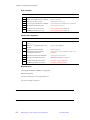
2.3 Homonuclear Decoupling
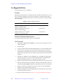
2.3 Homonuclear Decoupling
Use this procedure to calibrate homonuclear decoupling power values.
Samples
Table 4. Samples for Homonuclear Decoupling Test
Sample Tube Sample Part
(mm)
Number
Test Sample
0.1% ethylbenzene, 0.01% TMS,
99.89% deuterochloroform (CDCl3)
5
00-968120-70
0.1% ethylbenzene, 0.01% TMS,
99.89% deuterochloroform (CDCl3)
10
00-968123-70
Hardware
A 5-mm probe capable of 1H direct observe should be used for this test.
Procedure
1.
Enter rtp('/vnmr/tests/H1sn').
2.
Tune the probe. Set nt=1. Run a normal spectrum without decoupling.
3.
Set dm='nny'. Use the cursor and sd to set the decoupler on the central line of the
triplet, and then run a decoupled spectrum.
Possible dpwr values are 0 to 49 (49 is maximum power), in steps of 1.0 dB. The
best values of dpwr must be found by experiment. Too much power might show
increased noise; too little might not decouple the quartet. Setting dpwr=25 is a
good starting point.
4.
Observe that the quartet collapses to a single peak with no remaining evidence of
splitting.
5.
Write the results on the form in Chapter 5.5, “Console and Magnet Test Results,” .
01-999186-00 B0902
MERCURYplus Console Acceptance Tests & Specifications
31
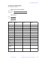
Chapter 2. Console and Magnet Test Procedures
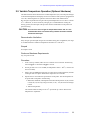
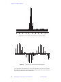
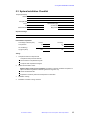
2.4 Magnet Drift Test
The magnet drift test is an overnight test.
Samples
Depending upon the probe, the concentration of H2O. The H2O concentrations are 1% for
the -01 and autotest samples and 2% for the -02 sample. Use the sample that provides a
signal with good a good signal to noise ratio, in most cases the 1% H 2O / 99% D2O samples
will a good signal.
Table 5. Sample for Magnet Drift Test
Sample
Sample Tube (mm) Sample Part Number
Doped 2-Hz H2O/D2O (0.1 mg/ml
GdCl3 in 1% H2O in D2O)
5
01-901855-01
Doped 2-Hz H2O/D2O (0.1 mg/ml
GdCl3 in 2% H2O in D2O)
5
01-901855-02
autotest sample; 0.1% 13C enriched
methanol in 1% H2O/99% D2O
5
01-96812068-xx
Probe and Hardware Requirements
A 5-mm probe capable of 1H direct observe is recommended.
Test Procedure
1.
Enter rtp('/vnmr/tests/shmd2o') to retrieve the test parameter set to the
current experiment.
2.
Tune the probe.
3.
Acquire a normal spectrum and shim the HDO signal to 2 to 3 Hz linewidth at 50%.
4.
Connect to the acqi window, turn the lock off, turn the spinner off, and set the
spinner speed to 0. Make sure the lock signal is on-resonance (the lock signal display
should be flat). Disconnect the acqi window. Then disconnect the lock cable from
the probe.
5.
Enter in='n' spin='n' nt=1 array('d1',11,3600,0) d1[1]=60.
This sets up an array of d1 values, with the first spectrum to be collected after 1
minute and subsequent spectra to be collected at 60 minute intervals.
6.
Enter ga to acquire the spectra. The test takes approximately 10 to 11 hours to finish.
7.
Phase the first spectrum by entering ds(1) to display the first spectrum of the array
and by entering lp=0 aph0 to apply a first-order phase correction to the spectrum.
8.
Enter ai to scale all of the spectra to the same vertical scale, and enter dssa to
display the arrayed spectra stacked vertically.
9.
Compare the frequency shift of the HDO peak of the arrayed spectra to the frequency
of the first spectrum in the array.
10. Write the results on the form in Chapter 5.5, “Console and Magnet Test Results,” .
32
MERCURYplus Console Acceptance Tests & Specifications
01-999186-00 B0902
2.5 Variable Temperature Operation (Optional Hardware)
2.5 Variable Temperature Operation (Optional Hardware)
This demonstration shows that the basic variable temperature (VT) unit and probe changes
to the desired temperature and displays on the VT controller. If the system is equipped with
a VT unit, read through the VT operation instructions before this demonstration.
Dry nitrogen is required as the VT gas if the requested temperature is over 100ο C or below
10ο C. Otherwise, air can be used. Dry nitrogen gas is recommended for cooling the
bearing, spinner, and decoupler. This prevents moisture condensation in the probe and
spinner housing.
CAUTION: The use of air as the VT gas for temperatures above 100ο C is not
recommended. Such use destructively oxidizes the heater element
and the thermocouple.
Demonstration Limitations
If dry nitrogen gas and liquid nitrogen are unavailable at the time of installation, the range
of VT demonstration is limited to temperatures between 30οC and 100οC.
Sample
No sample is used.
Probe and Hardware Requirements
Any VT probe is used.
Procedure
1.
In the config window, make sure VT Controller is set to Present. Alternatively,
enter vttype? to check that vttype is set to 2.
2.
Set N2 gas flow to 9.5 to 10.0 LPM (for temperatures below –100ο C, increase N2
flow to 12 LPM).
3.
Enter a value for temp, then enter su. For values below room temperature, the heat
exchanger must be in place. Maintain the temperature for 5 minutes.
4.
Operate the VT unit within the specifications of the probe. Test the temperature at
set points that correspond to the following:
• Maximum, minimum, and midpoint of the allowed temperature: 95, 80, 60 if air
is used; 120, 30, 20 if dry nitrogen is used; or 120, –100, 40 if a heat exchanger
is used.
• Ambient temperature.
The software limits the ramp rate to 12οC per minute up or down. Wait for the
temperature to equilibrate.
01-999186-00 B0902
MERCURYplus Console Acceptance Tests & Specifications
33
Chapter 2. Console and Magnet Test Procedures
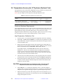
2.6 Temperature Accuracy for VT Systems (Optional Test)
The optional tests in this section check temperature accuracy calibrations for high and low
temperatures using ethylene glycol and or methanol, respectively.
Table 6 lists the samples for low-temperature and high-temperature tests.
Table 6. Samples for Optional VT Accuracy Test
Sample
Temperature Range
(°C)
Sample Tube Sample Part
(mm)
Number
100% methanol (reagent grade)
–50 to +25 (Low)
5
00-968120-80
100% ethylene glycol (reagent grade)
+25 to +100 (High)
5
00-968120-79
Probe and Hardware Requirements
The variable temperature accessory and a VT probe are required. Run VT tests with a 5-mm
probe capable of 1H direct observe from –150°C to +200°C. For probes that have a more
limited temperature range (particularly PFG probes), run the test at two or three
temperatures that fall within the VT range of the probe. These tests can also be run using
the 1H decoupling coil of the 5-mm broadband probe as 1H direct observe.
High-Temperature Calibrations Test
1.
Tune the probe. Use a 99.8% D2O sample (not supplied by Varian) for shimming.
2.
Enter rtp('/vnmr/tests/shmd2o') to retrieve the test parameter set to the
current experiment. Acquire a normal spectrum and shim the water signal to about 3
to 4 Hz linewidth at 50%.
3.
Replace the 99.8% D2O sample with the 100% ethylene glycol sample (Part No.
00-968120-79). Set the following parameters: pw=2 gain=5 (or some value that
doesn’t overload the receiver) sw=10000 at=2 nt=1 in='n'.
In the acqi window, set the lock to Off. Disconnect the lock cable and set
alock='n'. The test is run unlocked, because the sample has no deuterated
solvent to lock on. Enter su and check the probe tuning for the ethylene glycol
sample. Enter ga to acquire the spectrum. Place the cursor between the two peaks
and enter movetof to move the transmitter offset.
4.
Click the mouse on the Box menu button to call up right and left cursors. Position
the right and left cursors on the right and left peaks. Enter tempcal('glycol').
5.
Record the temperature reading from the VT controller (displayed face of the VT
controller) and the computer-calculated temperature based on the chemical shift
frequencies of the two peaks.
CAUTION: Extreme temperatures can damage the probe. The high and low
temperatues must be within the specified range of the probe.
34
6.
Enter temp=50 su to change the temperature to 50°C. Allow the sample to
stabilize at 50°C for at least 10 minutes after the VT controller has reached the final
temperature and regulated. Enter ga to acquire a spectrum. Repeat steps 4 and 5.
7.
Make sure that the VT gas flow and cooling air flow levels are between 9.5 to 10
LPM and gas flow to the probe is not restricted in any way. Enter temp=100 su to
change the temperature to 100°C.
MERCURYplus Console Acceptance Tests & Specifications
01-999186-00 B0902
2.6 Temperature Accuracy for VT Systems (Optional Test)
8.
Allow the sample to stabilize at 100°C for at least 10 minutes after the VT controller
has reached the final temperature and regulated. Enter ga to acquire a spectrum.
Repeat steps 4 and 5.
Low-Temperature Calibrations Test
CAUTION: For low-temperature calibrations, fill the VT dewar with liquid nitrogen.
If a chemical mixture is used instead of liquid nitrogen for lowtemperature calibrations, choose the chemical slurry carefully. A
mixture of crushed dry ice and acetone is not recommended, because
it will dissolve the polystyrene VT dewar.
1.
Tune the probe. Use a 99.8% D2O sample for shimming the probe.
2.
Enter rtp('/vnmr/tests/shmd2o') to retrieve the test parameter set to the
current experiment. Acquire a normal spectrum and shim the water signal to about
3 to 4 Hz linewidth at 50%.
3.
Replace the 99.8% D2O sample with the 100% methanol sample (Part No.
00-968120-80). Set the following parameters: pw=2 gain=5 (or some value that
doesn't overload the receiver) sw=10000 at=2 nt=1 in='n'.
4.
In the acqi window, set the lock to Off. Disconnect the lock cable and set
alock='n'. The test is run unlocked (the sample lacks deuterated solvent).
5.
Enter su and check the probe tuning for the methanol sample. Enter ga to acquire the
spectrum. Place the cursor between the two peaks and enter movetof to move the
transmitter offset.
6.
Click on the Box menu button to call up right and left cursors. Position the right and
left cursors on the right and left peaks, and enter tempcal('methanol').
7.
Record the temperature reading from the VT controller (displayed on the front face
of the VT controller). Record also the computer-calculated temperature based on the
chemical shift frequencies of the two peaks. If low-temperature calibrations are
performed immediately following high-temperature calibrations, allow the probe to
cool to room temperature before continuing with the rest of the procedure.
8.
Enter temp=-20 su to change the temperature to –20ο C. Allow the sample to
stabilize at –20° C for at least 10 minutes after the VT controller has reached the final
temperature and regulated. Enter ga to acquire a spectrum. Repeat steps 4 and 5.
9.
Enter temp=-80 su to change the temperature to –80° C. Allow the sample to
stabilize at –80° C for at least 10 minutes after the VT controller has reached the final
temperature and regulated. Enter ga to acquire a spectrum. Repeat steps 4 and 5.
10. After finishing the low-temperature test, enter temp='n' su to turn off the
temperature regulation. While keeping the dry nitrogen gas flowing to the probe and
upper barrel, remove the polystyrene VT dewar containing liquid nitrogen. The flow
of dry nitrogen gas to the probe will prevent condensation inside the probe. Allow
the dry nitrogen gas to flow through the probe and upper barrel for at least 15
minutes while the probe warms up to room temperature.
11. Plot a graph of the VT controller reading (horizontal axis) as compared with the
calculated VT reading from the chemical-shift differences between the two peaks
(vertical axis). Draw a straight line through the points.
01-999186-00 B0902
MERCURYplus Console Acceptance Tests & Specifications
35
Chapter 2. Console and Magnet Test Procedures
2.7 Stability Calibration for High-Stability VT (Optional Test)
This optional test is for high-stability VT units only (Part No. 00-992953-00). The test
demonstrates that the VT unit can hold the temperature with ± 0.1οC. The test requires
preconditioning of the laboratory air and restricts on the room temperature fluctuations.
Table 7. Samples for Optional High-Stability VT Test
Test Sample
Nucleus
Sample Tube
Part Number
(mm)
Doped 2-Hz H2O/D 2O (0.1 mg/ml GdCl3
in 1% H 2O in D2O)
1H
5
01-901855-01
Alternatively, the customer can request using a 10-mM DSS in D2O (sample volume of 0.6
ml in a 5-mm NMR tube) DSS= 3-(trimethylsilyl)-1-propane sulfonic acid. The customer
must make this sample using DSS and deuterium oxide (99.8 or 99.9 atom%D). Upon
request, Varian can make this sample if DSS is not available at the customer site.
Probe and Hardware Requirements
High-stability variable temperature accessory and a 5-mm probe capable of 1H direct
observe are required.
Test Procedure
1.
Enter rtp('/vnmr/tests/shmd2o') to retrieve the test parameter set to the
current experiment.
2.
Enter temp=40 at=10 sw=10000. Set pw to the 1H 90∞ pulse width for the
probe, and then enter spin='n' su.
3.
Allow the VT controller to regulate to 40ο C, which should be about 10ο higher than
the room temperature. Check that the probe is tuned.
4.
Acquire a normal spectrum by entering ga. Move the cursor to the DSS signal (rightmost peak). Enter movetof sw=1000 at=10.
5.
Acquire a normal spectrum and shim the DSS signal to about 0.6 Hz or less
linewidth at 50%. The sample of DSS in D2O should equilibrate at 40ο C for at least
2 hours before the next step.
6.
Enter in='n' spin='n' nt=1 and array('d1',73,600,0) d1[1]=0.
7.
This sets up an array of d1 values with the first spectrum to be collected at time 0
minutes, and subsequent spectra to be collected at 10 minute intervals for up to 12
hours. Enter ga to acquire the spectra. The test takes about 12hours to complete.
8.
After the spectra are acquired, phase the first spectrum by entering ds(1) to display
the first spectrum of the array, and by entering lp=0 aph0 to apply a first-order
phase correction to the spectrum.
9.
Enter ai to scale all of the spectra to the same vertical scale, and enter dssa to display
the arrayed spectra stacked vertically.
10. Measure the difference between the left-most peak and the right-most peak in Hz.
36
MERCURYplus Console Acceptance Tests & Specifications
01-999186-00 B0902
Chapter 3.
Consoles and Magnets Specifications
This section contains the following specifications:
•
•
•
•
•
3.1 “Homonuclear Decoupling” this page
3.2 “Variable Temperature Operation” this page
3.3 “Magnet Drift” page 38
3.4 “Temperature Accuracy for VT Accessories” page 38
3.5 “Stability Calibration for High-Stability VT Accessory” page 38
3.1 Homonuclear Decoupling
The quartet shows a single peak with no remaining evidence of splitting.
3.2 Variable Temperature Operation
For basic variable temperature (VT) accessories (Varian Part No. 00-992957-00),
demonstrate that the VT unit and probe go to the desired temperature as registered on the
window of the VT controller. If the system is equipped with a VT unit, the system user
should read through the VT operation instructions before the demonstration.
Dry nitrogen is required as the VT gas if the requested temperature is over 100οC or below
10οC. Otherwise, air can be used. For temperatures below –40οC, dry nitrogen gas is
recommended for cooling the bearing, spinner, and decoupler. This prevents moisture
condensation in the probe and spinner housing.
CAUTION: The use of air as the VT gas for temperatures above 100οC is not
recommended. Such use destructively oxidizes the heater element
and the thermocouple.
CAUTION: Extreme temperatures can damage the probe. The high and low
temperature must be within the specified range of the probe.
Demonstration Limitations
If dry nitrogen gas and liquid nitrogen are not available at the time of installation, the range
of VT demonstration is limited to temperatures between 30οC and 100οC.
Basic Specifications
The specifications for variable temperature ranges are listed with each probe.
01-999186-00 B0902
MERCURYplus Console Acceptance Tests & Specifications
37
Chapter 3. Consoles and Magnets Specifications
3.3 Magnet Drift
Table 8 lists the drift specifications for magnets. Specifications for nominal field decay rate
are less than or equal to the values listed in the table.
Table 8. Magnet Drift Specifications
System
(MHz/mm)
Field Strength
(T)
Nominal Field Decay Rate
(Hz/hr)
200/54
4.70
2
300/54
7.05
3
400/54
9.40
8
3.4 Temperature Accuracy for VT Accessories
The temperature reading displayed on the VT unit display panel should be within ±1ο C of
the actual temperature reading, as measured from the chemical shift.
3.5 Stability Calibration for High-Stability VT Accessory
The high-stability VT accessory holds the set temperature to within ±0.1οC. (±0.1οC =
0.001 ppm or in field dependent terms:, ±0.2 Hz at 200 MHz, ±0.3 Hz at 300 MHz, and
±0.4 Hz at 400 MHz)
38
MERCURYplus Console Acceptance Tests & Specifications
01-999186-00 B0902
Chapter 4.
Customer Training
Sections in this chapter:
•
•
•
•
•
•
•
•
•
4.1 “Where to Look for Answers” this page
4.2 “Host Computer Setup and Software Installation” page 41
4.3 “VNMR Directory Structure” page 41
4.4 “Managing Disk Space” page 43
4.5 “Tuning Probes” page 44
4.6 “Data Acquisition – Calibration and Indanone Spectra” page 44
4.7 “Magnet Maintenance” page 56
4.9 “Warranty and Who to Call for Assistance” page 58
4.8 “30-Day System Maintenance” page 57
This chapter describes training provided by the installer. This training is intended as a
general overview of the instrument, basic maintenance requirements, software features,
data acquisition and storage, file maintenance, and other routine tasks. Comprehensive
training classes are offered at various Varian, Inc. Applications Laboratories around the
world. Call your sales representative or contact the Varian, Inc. NMR systems office nearest
you for class offerings, schedules and cost.
4.1 Where to Look for Answers
Knowing where to look is the first
step to answering a question. All
manuals are available in hard copy
and can also be installed online.
Figure 14 shows the menu for the
MERCURYplus online manuals.
The online manuals are accessed
from the Workspace menu.
•
To access the Workspace menu
in Solaris 2.5 and newer, place
the mouse pointer on the
background and click with the
right mouse button.
•
To access the online manuals in
Solaris 2.6, click on Online
manuals on the Workspace menu.
•
To access the online manuals in Solaris 2.7 and later, select VNMR from the CDE
menu, then select Online Manuals.
01-999186-00 B0902
Figure 14. MERCURYplus Online Manual
Menu
MERCURYplus Console Acceptance Tests & Specifications
39
Chapter 4. Customer Training
Operation Manuals
After the installation has been finished you will find many of your routine questions
answered in the following manuals.
•
VNMR Command and Parameter Reference – Provides an alphabetical listing of the
VNMR commands, parameters, and macros. Refer to this manual when you are
working at the command line and you need to review a specific command.
•
Walkup NMR – Provides information about the walkup NMR interfaces available in
VNMR. Step-by-step instruction on setting up experiments using GLIDE and three
Tcl/Tk interfaces. Detailed system calibration and administration instructions are
provided in this manual.
•
Getting Started – Provides an overview of VNMR and instrument operations. This
manual covers the VNMR menu systems in detail, as well as command line operations,
locking and shimming, data acquisition parameters, probe tuning, digital signal
processing, and data processing, display, and plotting. Data management, storage,
retrieval, and archival is also addressed in this manual.
•
User Guide: Liquids NMR – Lists and explains how to set up all the standard
experiments provided with VNMR. Not every experiment listed can be run on every
system. The type and configuration of the instrument will determine which
experiments can be run. This is the manual to go to when you have very specialized
experimental requirements and will most likely be running the experiments from the
command line. You will also want to refer to this manual for a general overview of the
experiments that are automatically set up through the GLIDE and VNMR menu
systems.
•
User Guide: Solids NMR – Explains how the run CP/MAS experiments and describes
the XPOLAR1 pulse sequences.
•
System Administration – Provides detailed information on both the UNIX operating
system and VNMR software for the system administer is presented. Also included are
magnet maintenance and other administrative items.
Installations
40
•
MERCURYplus Installation Planning Guide – Provides site planning information for
MERCURYplus NMR spectrometer systems.
•
MERCURYplus Acceptance Test Procedures and Specifications – Covers the console
installation test procedures and specifications for the MERCURYplus spectrometer and
magnet. Included in this manual is the information used by the installation engineer in
the introductory training at the end of the installation. This manual does not cover the
probe test procedures.
•
VNMR and Solaris Software Installation – Details the installation of the Sun host
computer hardware and the Solaris and VNMR software. Detailed instructions on
system configuration are included here. Also included in this manual are instructions
for setting up various plotters and printers, and other administration tasks.
•
MERCURYplus CP/MAS Accessory Installation – Describes how to install and test the
CP/MAS accessory.
•
Probe installation, testing, and specifications manuals – Each type of probe has its own
installation, test, and specifications manual. In these manuals are the detailed
instructions for installing, tuning, testing the probe.
•
Accessory manuals – Each accessory is covered in an independent manual, which
contains installation, testing, and sometimes operation instructions.
MERCURYplus Console Acceptance Tests & Specifications
01-999186-00 B0902
4.2 Host Computer Setup and Software Installation
Technical References
•
System Schematics – Provides schematic and technical drawings for MERCURYplus
NMR spectrometer systems.
•
Technical Reference – Provides technical details of the spectrometer systems and
electronics.
•
System Description – Provides an overview of the MERCURYplus spectrometer
system and hardware.
•
User Programming – Provides details about the VNMR macro programming language
Magical II and pulse sequence statements. This manual contains the information
necessary to write custom macros, edit existing macro, write new pulse sequences, and
edit existing pulse sequences.
4.2 Host Computer Setup and Software Installation
Host computer setup and software installation is covered in detail in the VNMR and Solaris
Software Installation manual. NMR data is processed and displayed using the Sun host
computer, which is connected to the MERCURYplus NMR spectrometer with an Ethernet
cable.
Setting up the host computer involves the following general steps:
•
•
•
•
•
•
•
•
Unpacking the Sun computer
Connecting peripheral devices
Connecting the Sun computer to the MERCURYplus console
Installing the Solaris operating system software (including UNIX)
Installing the VNMR software
Configuring system hardware
Setting up user accounts
Setting printers and plotters
During this process, the Sun hard disk is laid out specifically for the needs of the VNMR
software and NMR operation. VNMR is installed in the directory /export/home and a
link called /vnmr is placed at the root level. User accounts are also installed in
/export/home.
Software is installed from CD-ROMs.
4.3 VNMR Directory Structure
An overview of the VNMR directory and file structure is shown in Figure 15. This file
structure is discussed in detail in the Getting Started manual.
The vnmr directory and file structure is set up with the global or system files and directories
that are have read and execute permission for all users and a group of user files and
directories that the user has read, write, and execute permissions. The global or system files
and directories are administrated by the user vnmr1. These files and directories are located
in /export/home/vnmr which is also accessed via the symbolic link in root, /vnmr.
Only the user vnmr1 and root have read, write, and execute permissions while others have
read and execute permission for files and directories in this area. If you must make changes
to VNMR files and directories, make them as vnmr1, not as root. The global or system files
01-999186-00 B0902
MERCURYplus Console Acceptance Tests & Specifications
41
Chapter 4. Customer Training
acq
KEY
acrobat
acqbin
directory
bin
autotest
file
fid1d.fid
fidlib
glide
help
Symbolic link
fid2d.fid
psg
adm
manual
app-defaults
dialoglib
kermit
asm
nuctables
lib
boot_message
maclib
vnmrmenu
menulib
vnmrrev
parlib
psglib
devicetable
user_templates
seqlib
gnu
shapelib
vnmr
gs
tablib
java
userlib
jre
shimmethods
tcl
shims
tmp
stdpar
text
fonts
root
tun
vxfonts
/
vnmr
conpar
devicenames
procpar
data1.fid
fid
myfids
log
data2.fid
vnmr1
exp1
export/home
user A
vnmrsys
seqlib
exp2
user seq
psglib
user seq.c
user B
maclib
user macros
user C
menulib
data
...
gshimlib
shapelib
autotest
help
templates
global
usr
Figure 15. VNMR Directory Structure
and directories contain macros, pulse sequences, binary files, optional VNMR software and
other files that have a common usage to all users. The users area contains files that are
owned by that user only.
When VNMR is installed and user accounts are established, certain directories are created
in the user’s home directory. In some cases these directories have the same names in both
the user work space in the /vnmr directory. When a command or instruction is executed
in vnmr by a user, VNMR first searches the user’s /vnmrsys/ directory for the command,
pulse sequence, etc. and then searches the global files in /vnmr. The System
Administration manual provides more detailed explanation. When creating custom macros,
42
MERCURYplus Console Acceptance Tests & Specifications
01-999186-00 B0902
4.4 Managing Disk Space
pulse sequences, menus, etc. it is good practice to give these files different names from the
similar files in /vnmr. If you want the customized macros, pulse sequences, etc. to be
available to all users, place them in the appropriate directory in /vnmr.
4.4 Managing Disk Space
The primary tool used by the system administrator to manage disk space is the UNIX
command df -k, see the System Administration manual for more details. This command
may be executed from any terminal window by any user. The output from this command
may look like this:
In this example, user accounts are placed in /export/home/<user> in the / (root)
File system
/dev/dsk/c0t0d0s0
/proc
fd
swap
/dev/dsk/c0t0d0s1
kbytes
2467482
0
0
243472
1372362
used
1818540
0
0
496
477485
avail
599593
0
0
242976
839983
capacity
76%
0%
0%
1%
37%
Mounted on
/
/proc
/dev/fd
/tmp
/space
directory. In some installations /export/home/<user> maybe a separate slice or
partition. There are two user accessible slices or partitions on this disk:
/dev/dsk/c0t0d0s0 mounted on /
/dev/dsk/c0t0d0s1 mounted on /space
When a partition or slice has reached 90% of its capacity it is time to do some maintenance.
UNIX will, in some cases allow the capacity to exceed 100% but this is not a good
condition. In the worst case, if the file system or slice containing the user’s vnmrsys
directory becomes full, the system may stop during a go or VNMR will not load or process
a data set. This situation can lead to data being lost.
Each user account has a vnmrsys directory contain maclib, seqlib and other needed
VNMR directories. Also within the user’s vnmrsys directory is a directory for each
experiment work space. Each work space or experiment provides temporary storage of the
data. The data in the experiment work space remains intact until an acquisition is started in
that experiment, a previously saved data set is loaded into the current experiment, or the
current experiment is deleted (see the Getting Started manual for details on creating and
deleting experiments in VNMR). The amount of disk space consumed by an experiment
depends upon the type of NMR experiment. To manage this, users should save their data
and either remove the experiment (delete the experiment workspace), execute a simple
experiment that uses little disk space (s2pul with np=8k for example), or load a
previously saved data set that has a small number of data points defining the FID.
Saving the data to a directory that is on the same slice or partition as the user’s vnmrsys
will not improve matters. The saved data should be placed in a directory on a different slice,
a different physical hard disk, a network server disk, or copied to some archive such as a
tape. The contents of directories such as maclib, seqlib, etc. do not tend to fill up with
old files that quickly except for users that are developing pulse sequences, macros, etc. Old
shim files tend to accumulate and can be cleared out from time to time. Periodic archiving
of important spectra to tape, central file servers, etc. and removal of these files from the disk
is necessary. Small data files can be copied to floppy disks. The use of tapes and floppy
disks is discussed in detail in the System Administration manual.
01-999186-00 B0902
MERCURYplus Console Acceptance Tests & Specifications
43
Chapter 4. Customer Training
4.5 Tuning Probes
Probe tuning is covered in Chapter 6 of the Getting Started manual.
Tuning operations and tuning ranges specific to each probe are covered in the manual
provided with the probe.
4.6 Data Acquisition – Calibration and Indanone Spectra
This section covers the calibration of the spectrometer and the acquisition of several 1D and
2D data sets using the 2% 2-ethyl-1-indanone sample, a typical small molecule with a
formula weight of 160 g/mole. Step-by-step instructions for calibration and acquiring
spectra of the 2-ethyl-1-indanone sample are given in 2.1 “AutoCalibration and GLIDE
Operation Demonstration” page 21 and 2.2 “Automated Data Acquisition” page 26 of this
manual and will not be repeated here.This section examines the order in which the
calibration data is acquired and resulting spectra.
The Calibration Process
Before acquiring spectra of a sample the spectrometer must first be calibrated. Calibration
is necessary if one of the following is true:
•
•
•
The probe has been changed
•
The calibration has not been run for several weeks (in this case it is simply a matter of
good laboratory practice to check the calibration).
The experiments are to be run at a different temperature than the last calibrations
Solvent changes significantly (i.e., an organic lock solvent vs. deuterium oxide lock
solvent)
All calibration spectra are saved in:
/export/home/vnmr1/vnmrsys/data/probe_calibs/
probename_calib_date.
Probe calibrations executed by vnmr1 are written to probe files one of two places.
•
If the probe name was created as a system probe and the probe name is unique (it does
not exist in /export/home/vnmr1/vnmrsys/probe) it is written to /vnmr/
probes/probe_name.
•
If the probe name was not created as a system probe or the probe name is not unique
(it does exist in /export/home/vnmr1/vnmrsys/probe) it is written to /
export/home/vnmr1/vnmrsys/probes/probe_name.
Before you begin the calibration procedure, check the probe parameter. This parameter
should be set to the probe that is currently installed in the magnet. If this is not true, set the
parameter to the name of the probe that is currently installed. The names of the installed
user level and system level probes can be obtained as shown in the following example:
Open a terminal window.
44
•
User level probes:
> cd ~/vnmrsys/probes
> lf
> hcn/ HFCN/...
•
System level probes:
MERCURYplus Console Acceptance Tests & Specifications
01-999186-00 B0902
4.6 Data Acquisition – Calibration and Indanone Spectra
> cd /vnmr/probes
> lf
> GHX/ BB10mm/ probe.tmplt...
The actual probe directory names on your system might be different. The probe parameter
must match one of the these directory names. If no calibration file exists for the probe or if
the probe is new, add the probe using the addprobe command.
At this point you are ready to begin the calibration process. Upon completion of the
calibration, 1D and 2D spectra of the test sample can be obtained using GLIDE.
After the 1D and 2D spectra are obtained, continue with the Automated Data Acquisition
described in 2.2 “Automated Data Acquisition” page 26. A series of spectra is acquired.
The first of the spectra, shown in Figure 16, is a 1H observe with CDCl3 as the lock solvent.
This data is saved as H1ref. This spectrum contains three 13CH3I resonances centered at
about 2.2 ppm. The center resonance is from the protons attached to carbon-12 and the two
outer resonances are from the protons attached to carbon-13. The other resonances in the
sample are from trimethylphosphite that has reacted with the methyl iodide (which was
initially 100% 13C enriched).
5.5
5.0
4.5
4.0
3.5
3.0
2.5
2.0
1.5
1.0
0.5 ppm
Figure 16. 1H Spectrum of 13C-Methyl Iodide
All trimethylphosphite has reacted to form a phosponate ester (CH3)P(=O)(OCH3)2. This
phosponate ester has a doublet at about 1.5 ppm, methyl group attached directly to 31P and
a triplet of doublets centered around 4 ppm that arise from 13C (outer pair of doublets) and
12
C inner doublet of the methyl ester. The analysis of this sample is fully discussed in an
article by Paul Keifer in Magnetic Moments (Keifer, P.A., Magnetic Moments, 1996, 8 (#2),
18–20). The reaction results in a sample is partially enriched to give approximately 60%
abundance of carbon-13 in methyl iodide. The natural abundance of carbon-13 is 1.1% so
this level of enrichment is more then adequate for the purposes of calibration.
01-999186-00 B0902
MERCURYplus Console Acceptance Tests & Specifications
45
Chapter 4. Customer Training
The next spectrum, shown in Figure 17, is an array of increasing 1H pulse widths based on
the 1H pulse you specified in the Acquire window. If you did not enter a value for the pulse
width it is set to the default targets pw90 is set to 15 µs and tpwr of 51.
Figure 17. 1H pw Array
The observe transmitter power is set to the value you specified and reduce by 3 for the first
test. If the resulting pw90 is shorter then the value you specified (or the default, if you did
not specify a pw90 target) the next test is started. If the pw90 is longer then the target, the
observe power is increased. Two attempts are made. If the calibration fails to achieve a
pw90 that is less than the specified pw90 the autocalibration exits. If either attempt yields
a pw90 that is less then the specified value the autocalibration routine adjusts the observe
power the remaining tests are aborted. If the pw90 is less then the specified value, the
autocalibration then adjusts the power until the measured pw90 is no greater then the
specified value but not more then 0.5 µs less than this value.The spectra from a successful
calibration are saved as H1pw90.
The carbon pwx90 calibration is the
next experiment. The pulse sequence
changes from s2pul to PWXCAL. The
specification for the carbon pw90 and
tpwr are used as the target values. If no
values were specified, the default values
of 15 µs at power, in this case pwxlvl,
of 51 are used as the target values. Just
as with the proton pw90 calibration, the
autocalibration makes two attempts to
achieve the specification and exits the
autocalibration if the target specification
is not reached after the second attempt.
The data from the PWXCAL are saved
as C13pwx and shown in Figure 18.
46
MERCURYplus Console Acceptance Tests & Specifications
Figure 18. 13C pwx Array
01-999186-00 B0902
4.6 Data Acquisition – Calibration and Indanone Spectra
The next two experiments are
run only if you have gradients.
The first experiment calibrates
the Z-gradient strength,
produces the profile shown in
Figure 19, and stores this
information in the parameter
gcal.
The next experiment calculates
the ratios of the gradients to be
used in various indirect
detection experiments and stores
this information in the parameter
Cgrad, Figure 20.
Figure 19. Gradient Profile
The next calibration is carbon
observe pulse width and the
pulse sequence is changed to
s2pul for direct observation of
the carbon. The calibration will
follow the same pattern as the
calibration of the proton pw90
and the carbon pwx90 using
default values for target values if
no target specification is given.
A reference carbon spectrum is
obtained first The full reference
Figure 20. Gradient Calibrations
spectrum contains three sets of
resonances, at the far right
(approximately –22 ppm) is the
13
C resonance from methyl iodide, the doublet at 10 ppm is from the 13C resonance from
the phosponate methylester, and the 1:1:1 triplet (far left) at 78ppm is the 13C resonance of
chloroform-d, 2HCCl3. The carbon pw90 calibration is analogous to the proton calibration.
The reference carbon spectrum, shown in Figure 21, is saved as C13ref.
The carbon observe pw90 is determined using a pw array, see Figure 22, and saved as
C13pw90.
The final calibration is of the proton decoupler. The first calibration step determines the
value of γH2 at a decoupler power of 40 (the default value).
This measurement is made using continuous wave, cw, decoupling. The pulse sequence is
the same as in the previous experiment, carbon observe with proton decoupling, except pw
is now set to a fixed value, decoupler modulation mode; dmm is set to 'c', decoupler mode
dm; is set to 'yyy', and the decoupler offset; dof is arrayed to produce the spectra
shown in Figure 23.
From these spectra, the first estimate of the proton decouple pw90 is made. Using the
relationship between the pulse width and the decoupler field strength, γH 2, shown in the
equation below, the decoupler pw90 is determined.,
1
γH2 = ---------------------4 ( pw90 )
The sequence is now set to ppcal and the proton decoupler 90° pulse, pp, is determined.
These spectra, shown in Figure 24, are saved as Hdec_dept.
01-999186-00 B0902
MERCURYplus Console Acceptance Tests & Specifications
47
Chapter 4. Customer Training
-5
-10
-15
-20
-25
-30
-35
-40
-45
ppm
Figure 21. Proton Coupled 13C Spectrum of 13C-Methyl Iodide
Figure 22. 13C Observe pw Array of Proton Coupled Spectra
These parameters and calibrations are used to setup WALTZ decoupling. This completes
the calibrations. During the calibration procedure, spectra and the array values are plotted
to provide a permanent record of the calibrations.
48
MERCURYplus Console Acceptance Tests & Specifications
01-999186-00 B0902
4.6 Data Acquisition – Calibration and Indanone Spectra
Figure 23. Proton Decoupler dof Array
Figure 24. Calibration of the Decoupler 90° Pulse Width, pp
01-999186-00 B0902
MERCURYplus Console Acceptance Tests & Specifications
49
Chapter 4. Customer Training
2-Ethyl-1-Indanone Spectra
The proton NMR shows
several distinct features.
First, there are some
impurities in the sample.
These impurities, shown
in Figure 25, are at the
2% level and some
crosspeaks will show up
in the 2D. The very large
triplet for the methyl
group has 13C satellites
at J=125 Hz. The
singlet at 7.24 ppm is the
residual CHCl3 in the
CDCl3 solvent.
O
Hf
Hg
7
6
5
2
9
4
Hh
Ha
1
8
Hc
3
Hb
10
CH3
He H
d
Hi
CHCl 3
8
7
6
5
4
3
2
1
ppm
The protons are assigned
Figure 25. Proton Spectrum of 2-Ethyl-1-Indanone
in the two expansions.
The assignments are based upon the 2D data for the compound. The protons of the two CH 2
groups in the molecule, shown in Figure 26, are magnetically nonequivalent and show up
as individual multiplets. The signals at 1.9 ppm and 1.55 ppm belong to protons on carbon
10. The two double doublets at 2.8 ppm and 3.26 ppm belong to protons on carbon 3. A
complex multiplet at 2.6 ppm is the single proton on carbon 2.
O
Hf
Hg
7
6
5
Hh
4
3.2
2
9
3
Hc
Hb
10
CH3
He H
d
Hi
3.4
Ha
1
8
3.0
2.8
2.6
2.4
2.2
2.0
1.8
1.6
1.4
1.2
1.0
ppm
Figure 26. Aliphatic Region of the 2-Ethyl-1-Indanone Spectrum
The protons of the aromatic ring, shown in Figure 27, are assigned based on the gHMBC
and gCOSY data. Some minor impurities can be seen as well as the residual CHCl3 signal.
If the sample is shimmed very well there may be some truncation artifact on the CHCl3
signal.
50
MERCURYplus Console Acceptance Tests & Specifications
01-999186-00 B0902
4.6 Data Acquisition – Calibration and Indanone Spectra
O
Hf
Hg
7
6
8
5
9
Hh
4
Ha
1
2
3
Hc
Hb
10
CH3
He H
d
Hi
Protons H f,g,h,i
CHCl 3
7.9
7.8
7.7
7.6
7.5
7.4
7.3
7.2
ppm
Figure 27. Aromatic Region of the 2-Ethyl-1-Indanone Spectrum
The gradient COSY shows cross peaks describing the coupling pathways. Some smaller
cross peaks are also present in the spectrum which actually arise from the impurities shown
in Figure 28. An example of this is the cross peak at 3.5 ppm.
The methyl triplet in Figure 29 shows major cross peaks to the H10 protons. The
multiplicity of the H10 and H2 protons cross peaks show that they are weakly coupled (the
J value is small).
Assignment of the aliphatic region, begins with H7, the most deshielded proton, Figure 30.
From H7 direct connectivity is apparent to H6. The rest of the assignment is H6 to H5 (the
other triplet) and then to H4.
The assignment of H7 to the signal at 7.72ppm is confirmed by the gHMBC data.
TOCSY is a phase sensitive experiment. The cross peaks are narrower than in the COSY
giving higher “resolution”. Correlations among all protons in a spin system are observed in
the TOCSY spectrum, see Figure 31. The critical parameter is mix. In this case mix is 0.08
seconds which is sufficient to show correlations throughout the entire spin system. Shorter
mix times will reveal fewer correlations.
The expansion shows the completely defined spin system starting with the CH3 group and
ending with protons on C10, Figure 32. A total of 5 crosspeaks are seen in the row]
The indanone sample does not have any significant NOE crosspeaks, Figure 33. The main
area of interest in this spectrum is to note that the diagonal will be negative and the NOESY
crosspeaks will be positive. Crosspeaks which appear to have both positive and negative
components are actually not NOE correlations but coupling artifacts.
01-999186-00 B0902
MERCURYplus Console Acceptance Tests & Specifications
51
Chapter 4. Customer Training
F2
(ppm)
2
Impurities
3
4
5
6
7
8
8
7
6
5
4
3
2
1
F1 (ppm)
Figure 28. Gradient COSY of 2-Ethyl-1-Indanone
In the gHSQC (and HSQC) experiment, see Figure 34 the protons correlate with the
carbons to which they are attached. The detected nucleus is 1H and this results in a higher
signal to noise then the 13C detected hetcor experiment. When compared to the HMQC
experiment, the HSQC experiment has the advantage that the 1H – 1H homonuclear
coupling do not evolve. As a result the resolution in the 2D plane is higher in the HSQC
experiment. The higher resolution has the added advantage of improving the signal to noise.
The version of the HSQC experiment supplied with the MERCURY has the added benefit
that it will distinguish –CH, –CH2, and –CH3 groups. In this case phase is indicated by
whether the crosspeak is filled in with multiple contours (above the plane) or is a single
contour (below the plane).
By contrast to the gHSQC experiment, the gHMBC (and HMBC) experiment shows long
range (mostly 2 and 3 bond) 1H – 13C correlations. This shows connectivity between the
non - protonated carbonyl and the protons on C-2.
52
MERCURYplus Console Acceptance Tests & Specifications
01-999186-00 B0902
4.6 Data Acquisition – Calibration and Indanone Spectra
O
Hf
Hg
7
6
5
Hh
4
7
6
H
a
1
8
9
5
2
3
Hh
10
Hc
4
Ha
1
8
2
H9b
3
Hc
Hb
10
CH3
He H
d
Hi
CH3
F2
(ppm)
He H
d
Hi
O
Hf
Hg
F2
(ppm)
2
1.2
3
1.4
1.6
4
1.8
2.0
5
2.2
6
2.4
2.6
7
2.8
8
3.0
8
3.2
7
6
5
4
3
2
1
F1 (ppm)
3.4
3.6
Figure 31. TOCSY of
2-Ethyl-1-Indanone shows Correlations Among All Protons
3.8
3.8
3.4
3.0
2.6
2.2
1.8
1.4
1.0
F1 (ppm)
Figure 29. Gradient COSY (gCOSY) of Aliphatic Region of 2-Ethyl-1-Indanone
CHCl 3
O
Hf
Hg
7
6
5
Hh
8
4
Hi
F2
(ppm)
7.1
9
Ha
1
2
3
Hc
Hb
10
CH3
He H
d
7.2
7.3
7.4
7.5
7.6
7.7
7.8
7.9
8.0
7.9
7.8
7.7
7.6
7.5
7.4
7.3
7.2
7.1
F1 (ppm)
Figure 30. Gradient COSY (gCOSY) of the Aromatic Region of 2-Ethyl-1-Indanone
01-999186-00 B0902
MERCURYplus Console Acceptance Tests & Specifications
53
Chapter 4. Customer Training
O
Hf
Hg
7
6
5
Hh
4
Hi
8
9
Ha
1
2
3
He H
d
Hc
Hb
10
CH3
F2
(ppm)
2
3
4
5
6
7
8
8
7
6
5
4
3
2
1
F1 (ppm)
Figure 31. TOCSY of 2-Ethyl-1-Indanone shows Correlations Among All Protons
54
MERCURYplus Console Acceptance Tests & Specifications
01-999186-00 B0902
4.6 Data Acquisition – Calibration and Indanone Spectra
O
Hf
Hg
7
6
5
Hh
4
Ha
1
8
9
2
Hc
3
Hb
10
CH3
F2
(ppm)
He H
d
Hi
2
3
4
5
6
7
8
8
7
6
5
4
3
2
1
F1 (ppm)
Figure 33. NOESY Spectrum of 2-Ethyl-1-Indanone
O
Hf
Hg
7
6
5
Hh
4
Hi
8
9
Ha
1
2
Hc
3
He H
d
Hb
10
CH3
F2
(ppm)
2
3
4
5
6
7
130
110
90 80 70 60 50 40 30 20
F1 (ppm)
Figure 34. HSQC Spectrum of 2-Ethyl-1-Indanone
01-999186-00 B0902
MERCURYplus Console Acceptance Tests & Specifications
55
Chapter 4. Customer Training
4.7 Magnet Maintenance
Magnet maintenance is described in Chapter 22 of the System Administration manual.
Magnet maintenance consists of three basic elements:
•
•
•
Periodic checks of the cryogen levels and boil off rates
Liquid nitrogen fill
Liquid helium fill.
WARNING: The extremely low temperature of liquefied helium and nitrogen can
cause skin damage similar to high-temperature burns. Contact with
the cold gas evolving from the liquid may produce the same effect.
Delicate body tissues, such as the eyes, are easily damaged by
exposure to cold gas or liquid. Skin can stick to metal that is
refrigerated by liquid helium and can tear when pulled away.
Immediately flood with large quantities of unheated water any area of
the body that is “burned” by liquid or cold gas, and then apply cold
compresses. If the skin is blistered or there is any chance the eyes are
affected, immediately seek medical treatment.
WARNING: Wear goggles and loose-fitting protective gloves while working with
cyrogens.
Periodic checks
A record or log book should be kept with dates, flow rates, cryogen levels, and notes
on changes made to or observed in the magnet. A typical schedule of checks would
be:
Weekly
1.
Check air line traps for dirt or condensed water.
2.
Record the following readings (note that the flow rates of nitrogen and helium
depends on a variety of factors such as atmospheric pressure and a high reading is
not necessarily an indication of a problem, but it is worth investigating):
•
•
•
Pressure at the air valve for the magnet.
Liquid nitrogen level.
Readings on the nitrogen and helium flow meters.
Twice Each Month
•
Check liquid helium level.
Monthly or Bimonthly
•
56
Check signal-to-noise and lineshape using the standard proton sample, the 13C 90°
pulse width, and the decoupler field strength. Keep the resulting spectra and parameter
in a secure place for future reference.
MERCURYplus Console Acceptance Tests & Specifications
01-999186-00 B0902
4.8 30-Day System Maintenance
Filling Cryogens
All cryogens should be delivered in nonmagnetic dewars. Consult the manual supplied by
Oxford complete instructions and for more detailed information on cyrogen fill intervals
and capacities.
Liquid Nitrogen
The interval between liquid nitrogen fills it nominally 2 weeks. The Oxford manual that is
supplied with the magnet should be consulted for the exact interval between nitrogen fills.
CAUTION: Failure to maintain the correct liquid nitrogen levels will lead to
excessive liquid helium boil off which in turn may lead to a quench of
the magnet.
Liquid Helium
The interval between liquid helium fills is dependent upon the type of dewar. There are
standard and long hold Dewars available for some magnets. The recommended refill
interval is specified in the Oxford manual that is supplied with the magnet should be
consulted for the exact interval between liquid helium fills and specific details on routine
liquid helium fills. Depending upon the type of dewar, the exact details and procedures for
liquid helium filing will vary, consult the Oxford Magnet Manual supplied with your
magnet.
CAUTION: Failure to maintain the correct liquid helium levels may lead to a
quench of the magnet.
WARNING: Wear goggles and loose-fitting protective gloves while working with
cyrogens.
4.8 30-Day System Maintenance
The following procedures must be performed while logged in as vnmr1.
1.
Updating Solvent Shims
Reshim lineshape and then save shims to /vnmr/shims/acetone.
Refer to the Acceptance Test Procedures & Specifications for the specific probe and
to Getting Started – Section 6.9 Saving and Retrieving Shim Values
2.
Check Calibration of pw90 and tpwr, as described in 2.1 “AutoCalibration and
GLIDE Operation Demonstration” page 21.
3.
Update the lock frequency, as described in the Software Installation manual,
Appendix B.
4.
Check magnet drift, as described in 2.4 “Magnet Drift Test” page 32.
5.
Perform hard drive maintenance: delete unused files, directories, old FIDs, macros,
shims, or users.
01-999186-00 B0902
MERCURYplus Console Acceptance Tests & Specifications
57
Chapter 4. Customer Training
4.9 Warranty and Who to Call for Assistance
The installation engineer will explain the standard warranty terms. Non standard warranty
terms, if included as a condition of sale, are detailed in the sales contract and will not be
covered by the installation engineer.
Table 9. Who to Call for Assistance
Online Customer Support and Information
Service and Technical Support
http://www.varianinc.com/nmr/service
Applications Support
http://www.varianinc.com/nmr/apps
Sales Support
http://www.varianinc.com/nmr/contact
Product Information
http://www.varianinc.com/nmr/products
In warranty Service
Location
Phone Number
United States and North America
Palo Alto, California
1.800.356.4437
Europe
Local Sales Office
See page 17
Other International
Local Sales Office
See page 17
Technical Support
Location
Phone Number
United States and North America
Palo Alto, California
1.800.356.4437
Europe
Oxford, UK
44.1865.388.800
Other International
Local Sales Office
See page 17
Location
Phone Number
United States and North America
Palo Alto, California
1.800.356.4437
Europe
Local Sales Office
See page 17
Other International
Local Sales Office
See page 17
Post Warranty Support
Applications Support
Location
Phone Number
Palo Alto, California
650.424.4526
Columbia, Maryland
410.381.7229
Europe
Darmstadt, Germany
49.6152.703.253
Japan
Tokyo, Japan
81.3.5232.1211
Other International
Local Sales Office
See page 17
United States and North America
58
Webb Addresses
MERCURYplus Console Acceptance Tests & Specifications
01-999186-00 B0902
Chapter 5.
Acceptance Test Results
This chapter contains the following forms for recording system information and acceptance
test results:
•
•
•
•
•
5.1 “Computer Audit” page 61
5.2 “Installation Customer Training Checklist” page 63
5.3 “System Installation Checklist” page 65
5.4 “Supercon Shim Values” page 67
5.5 “Console and Magnet Test Results” page 69
01-999186-00 B0902
MERCURYplus Console Acceptance Tests & Specifications
59
Chapter 5. Acceptance Test Results
Notes:
60
MERCURYplus Console Acceptance Tests & Specifications
01-999186-00 B0902
5.1 Computer Audit
5.1 Computer Audit
Information about your site (please print):
Company/University
Address
Principal User
Phone
Spectrometer type
Fax
Console S/N
Sales Order No.
Delivery (month/day)
Information on each computer (additional forms are on the back of this page). Include
computers directly attached to the spectrometer, computers (networked or non-networked,
on-site or off-site) used to process NMR data using Varian’s VNMR software, and
computers (on-site and off-site) used to process data collected on this spectrometer with
software from other vendors.
Information on computer ____ of ____ (e.g., 1 of 3)
Manufacturer
Model no.
Computer S/N
Purchased from
Memory (Mbytes)
Screen size (in.)
Peripherals: Internal hard disk (Mbytes)
External hard disk (Mbytes)
Serial no.
Tape drive size
Serial no.
CD-ROM drive model
Serial no.
Printer model
Serial no.
Plotter model
Serial no.
Terminal model
Serial no.
Other peripheral
Serial no.
Computer function: NMR host
Workstation running VNMR
on-site or off-site
Workstation running other NMR software
on-site or off-site
Workstation running VNMR and other NMR software
on-site or off-site
VNMR version
Operating system
The above computer audit was performed during installation of the system.
Varian Representative
Date
I certify that the information on this form is accurate and that all computers to be used to
run VNMR software (including variants VnmrS, VnmrX, VnmrI, VnmrSGI, and VnmrV),
or to run other software to process data obtained on this spectrometer, have been included
in the audit (including those previously registered as part of purchases of other Varian NMR
spectrometers).
Customer Representative
01-999186-00 B0902
Date
MERCURYplus Console Acceptance Tests & Specifications
61
Chapter 5. Acceptance Test Results
Use these forms for additional computers. If more forms are needed, copy this page. Attach all
copies to the Computer Audit.
Information on computer ____ of ____ (e.g., 2 of 3)
Manufacturer
Model no.
Computer S/N
Purchased from
Memory (Mbytes)
Screen size (in.)
Peripherals: Internal hard disk (Mbytes)
External hard disk (Mbytes)
Serial no.
Tape drive size
Serial no.
CD-ROM drive model
Serial no.
Printer model
Serial no.
Plotter model
Serial no.
Terminal model
Serial no.
Other peripheral
Serial no.
Computer function: NMR host
Workstation running VNMR
on-site or off-site
Workstation running other NMR software
on-site or off-site
Workstation running VNMR and other NMR software
on-site or off-site
VNMR version
Operating system
Information on computer ____ of ____ (e.g., 3 of 3)
Manufacturer
Model no.
Computer S/N
Purchased from
Memory (Mbytes)
Screen size (in.)
Peripherals: Internal hard disk (Mbytes)
External hard disk (Mbytes)
Serial no.
Tape drive size
Serial no.
CD-ROM drive model
Serial no.
Printer model
Serial no.
Plotter model
Serial no.
Terminal model
Serial no.
Other peripheral
Serial no.
Computer function: NMR host
VNMR version
62
Workstation running VNMR
on-site or off-site
Workstation running other NMR software
on-site or off-site
Workstation running VNMR and other NMR software
on-site or off-site
Operating system
MERCURYplus Console Acceptance Tests & Specifications
01-999186-00 B0902
5.2 Installation Customer Training Checklist
5.2 Installation Customer Training Checklist
Customer Information
Company/University
Address
Principal User
Phone
Spectrometer type
Fax
Console S/N
Sales Order No.
Magnet S/N
Magnet Familiarization:
Done Topic
Reference
Overall magnet familiarization
Oxford Magnet Reference Manual
LHe and LN 2 top off procedures
Oxford Magnet Reference Manual and Lhe refill video
Use of flow meters
Oxford Magnet Reference Manual
Antivibration system operation
Antivibration Accessory Installation Manual
Posting of magnetic field warning signs
Installation Planning Guide
Probes:
Done Topic
Reference
Probe installation
Choose a specific probe manual
removal, tuning, and filter setup for ID
and TR experiments
AutoSwitchable probes
Broadband probes
Indirect Detection probes
Nano probes
Switchable probes
Flow probes
VT system installation
Variable Temperature Unit Installation
VT system operation
User Guide: Liquids NMR, Chapter 8
Console:
Done Topic
Reference
Major component overview
System Overview
Shut down procedures
System Administration manual, 3.1, 3.2, 3.3
Host console connection and overview
System Administration manual, 3.1
01-999186-00 B0902
MERCURYplus Console Acceptance Tests & Specifications
63
Chapter 5. Acceptance Test Results
Host Computer:
Done Topic
Reference
Host computer setup
Software Installation
Solaris and VNMR software installation
Software Installation
Directory structure overview
Getting Started manual, 1.4
Using acqproc and makeuser commands
System Administration and Software Installation
Shutdown and startup of UNIX
System Administration, 5.5
Storage devices and accessories
System Administration, Chapter 10
VNMR file backup and recovery
System Administration, Chapter 10
Spectrometer Operation:
Done Topic
Reference
Standard parameter and probe calibration
setup
Walkup NMR
Basic 1H/13C experiment setup using
GLIDE
Walkup NMR, Chapter 2
COSY demonstration GLIDE
Walkup NMR, 3.8
Homonuclear and heteronuclear
decoupling demonstration
Getting Started manual, 7.2 and Acceptance Test
Procedures
Manual lock and shim demonstration
Getting Started manual, 6.10
Basic spectral display procedures
Getting started manual, 4.10 and 9.5
Gradient shimming demonstration
User Guide: Liquids NMR, 11.6
CP/MAS experiment information
User Guide: Solid-State NMR
Miscellaneous:
ATP signoff and Walkup NMR demo, if applicable
Hallmark of Quality
Customer contacts for service, applications etc.
Accessory training as required
Varian Representative
Date
Customer Representative
Date
64
MERCURYplus Console Acceptance Tests & Specifications
01-999186-00 B0902
5.3 System Installation Checklist
5.3 System Installation Checklist
Company/University
Address
Principal User
Phone
Spectrometer type
Fax
Console S/N
Sales Order No.
Magnet S/N
Shipment Damage:
Preinstallation Preparation:
Line voltage measured (Vac):
console
accessory
air
N2
LHe
LN
Line pressure:
Air conditioning:
Cryogens (liters):
Testing:
1.
Acceptance tests and computer audit
Acceptance tests procedures finished
Test results form completed and signed
Computer audit completed and signed
2.
System documentation review
Software Object Code License Agreement (acceptance of product constitutes acceptance of
object code license regardless of whether agreement is signed or not)
Varian and OEM manuals
Explanation of warranty and where to telephone for information
3.
Installation Training
4.
Installation Customer Training Check list
01-999186-00 B0902
MERCURYplus Console Acceptance Tests & Specifications
65
Chapter 5. Acceptance Test Results
Notes:
66
MERCURYplus Console Acceptance Tests & Specifications
01-999186-00 B0902
5.4 Supercon Shim Values
5.4 Supercon Shim Values
Fill in the following information:
Magnet Frequency and Serial Number
Magnet Frequency
Serial Number
Measurement in
Helipot
Amps
Measurements
Measurement
1. Date:
2. Date:
3. Date:
Z0
Z1
Z2
Z3
Z4
X
Y
ZX
ZY
XY
X2–Y2
Drift
Spacers
Main Field Current
Customer
Signature:
Varian
Representative
Signature:
01-999186-00 B0902
MERCURYplus Console Acceptance Tests & Specifications
67
Chapter 5. Acceptance Test Results
Notes:
68
MERCURYplus Console Acceptance Tests & Specifications
01-999186-00 B0902
5.5 Console and Magnet Test Results
5.5 Console and Magnet Test Results
Fill in the following information:
From “AutoCalibration and GLIDE Operation Demonstration,” page 21
From “Automated Data Acquisition,” page 26
From “Homonuclear Decoupling,” page 31
From “Magnet Drift Test,” page 32
From “Variable Temperature Operation (Optional Hardware),” page 33
From “Temperature Accuracy for VT Systems (Optional Test),” page 34
From “Stability Calibration for High-Stability VT (Optional Test),” page 36
Varian Representative
Date
Customer Representative
Date
01-999186-00 B0902
MERCURYplus Console Acceptance Tests & Specifications
69
Chapter 5. Acceptance Test Results
Notes:
70
MERCURYplus Console Acceptance Tests & Specifications
01-999186-00 B0902
Index
Index
Numerics
E
180° pulse, 15
2-Ethyl-1-indanone in chloroform- d
automated data acquisition, 26
2-ethyl-1-indanone in chloroform-d
sample part number, 26
90° pulse, 15
ethylene glycol, 34
experiment setup, 13
F
A
Acceptance Test Procedures and Specifications, 40
acceptance test specifications overview, 12
acceptance tests documentation, 16
acceptance tests objectives, 11
Accessory Manuals, 40
addprobe, 22
air line traps, 56
APT demonstration, 26
Attached Proton Test, 26
AutoCalibration, 21, 26
automated data acquisition, 26
C13 and C13 Detected experiments, 29
H1 and H1 detected experiments, 27
sample required, 26
automatic teller machine (ATM) cards caution, 9
B
basic system operation, 13
broadband operation, 13
C
calibrate
H,C,Ind.Det.&Grad. (CH3I), 24
LOCK gmap and z0, 22
Z0 and Make LOCK gmap, 22
Calibration
training, 44
adding a probe, 44–45
calibration process, 45
calibrations, 48
cautions defined, 7
Command and Parameter Reference, 40
computer audit form, 12, 61
console demonstration, 13
console test procedures, 21
CP/MAS experiments, 40
credit cards caution, 9
cryogenics handling procedures, 13
D
decoupling, 13
demonstration of system, 13
DEPT demonstration, 26
Distortionless Enhancement by Polarization
Transfer, 26
dpwr parameter, 31
01-999186-00 B0902
Filling Cryogens, 57
Liquid Helium, 57
Liquid Nitrogen, 57
flammable gases warning, 8
flow rates of nitrogen and helium, 56
flowmeters, 13
G
gamma H2 pw90 relationship, 47
Getting Started manual, 40
GLIDE AutoCalibration, 21–26
probe and system calibration, 24–25
reviewing probe and system calibrations, 25
Z0 and Make LOCK gmap, 22–23
H
h1sn file, 31
helium contact with body, 8
helium flowmeter, 56
helium gas flowmeters caution, 10
high-power amplifiers cautions, 10
high-stability VT units (optional test), 36
High-Temperature Calibrations Test (optional), 34
homogeneity settings, 15
homonuclear decoupling test, 31
I
installation checklist, 63, 65
installation engineer, 11
Installation Planning Guide, 40
installation planning guide, 14
L
lineshape determination
digital, 15
from a plot, 16
linewidth measurement, 16
liquid helium
level in dewar, 56
liquid nitrogen, 33, 37
loading programs, 13
Low-Temperature Calibrations Test (optional), 35
M
magnet demonstration, 13
magnet drift test
procedure, 32
sample and part number, 32
magnet quench warning, 8
magnet refilling, 13
MERCURYplus Console Acceptance Tests & Specifications
71
Index
magnet test procedures, 21
magnetic media caution, 9
managing disk space, 43
metal objects warning, 7
methanol, 34
System Demonstration, 13
system demonstration, 13
system documentation review, 12
system installation checklist, 65
System Maintenance, 30 day check list, 57
N
T
nitrogen contact with body, 8
nitrogen flowmeter, 56
nitrogen gas, 33, 37
nitrogen gas flowmeters caution, 10
noise region, 16
Technical References
System Description, 41
System Schematics, 41
Technical Reference, 41
User Programming, 41
temperature accuracy for VT systems, 34
test conditions, 14
test parameters, 15
training
2-ethyl-1-indanone spectra, 50–52
training seminars, 13
tuning probes, 44
O
OEM manuals, 12
P
pacemaker warning, 7
Periodic checks, 56
policies for acceptance test specifications, 12
preinstallation checklist, 65
Probe Acceptance Test Procedures and
Specifications Manuals, 40
probe and system calibrations, 24–25
probe demonstration, 13
probe tuning, 44
prosthetic parts warning, 7
pw parameter, 15
Q
quarter-wavelength cable, 14
R
radio-frequency emission regulations, 10
relief valves warning, 9
removable quench tubes warning, 9
reviewing the probe calibration, 25
rts command, 15
S
safety precautions, 7, 9
samples required for acceptance testing, 14
sensitivity tests, 15
shim parameters, 15
shipment damage, 65
signal-to-noise measurement, 15
skin damage from helium and nitrogen, 56
Software Installation, 40
Software Object Code License Agreement, 12
solids high-power amplifiers caution, 10
spectra
13C observe pw array, 48
spinning speed, 15
streaming magnetic tape unit, 13
svs command, 15
System Administration manual, 40
72
U
updated, 23
User Guide
Solids NMR, 40
User Guide: Liquids NMR manual, 40
V
variable temperature control
demonstration, 33
temperature accuracy (optional), 34
Varian manuals, 12
Varian Sales Offices, 17
VNMR
directory and file structure, 41
vortexing, 15
VT experiment warning, 8
W
Walkup NMR manual, 40
warnings defined, 7
warranty coverage, 12
weekly maintenance, 56
where to look for answers, 39
Installations, 40
Operations, 40
Technical References, 41
Varian Sales Offices, 17
Who to Call for Assistance, 58
Who to Call for Assistance, 58
Z
Z0 and Make LOCK gmap calibration, 22–23
MERCURYplus Console Acceptance Tests & Specifications
01-999186-00 B0902