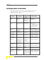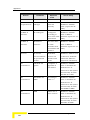
1
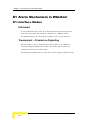
WALKair™ 3000
Troubleshooting Guide
Version 5.0
March 2007
P/N 214420
Error! No text of specified style in document.
Legal Rights
Legal Rights
© Copyright 2006 Alvarion Ltd. All rights reserved.
The material contained herein is proprietary, privileged, and
confidential and owned by Alvarion or its third party licensors. No
disclosure thereof shall be made to third parties without the express
written permission of Alvarion Ltd.
Alvarion Ltd. reserves the right to alter the equipment specifications
and descriptions in this publication without prior notice. No part of this
publication shall be deemed to be part of any contract or warranty
unless specifically incorporated by reference into such contract or
warranty.
Trade Names
Alvarion®, BreezeCOM®, WALKair®, WALKnet®, BreezeNET®,
BreezeACCESS®, BreezeMANAGE™, BreezeLINK®, BreezeConfig™,
BreezeMAX™, AlvariSTAR™, BreezeLITE™, AlvariCRAFT™, MGW™,
eMGW™, WAVEXpress™, MicroXpress™, WAVEXchange™, WAVEView™,
GSM Network in a Box and TurboWAVE™ and/or other products and/or
services referenced here in are either registered trademarks, trademarks
or service marks of Alvarion Ltd.
All other names are or may be the trademarks of their respective
owners.
Statement of Conditions
The information contained in this manual is subject to change without
notice. Alvarion Ltd. shall not be liable for errors contained herein or for
incidental or consequential damages in connection with the furnishing,
performance, or use of this manual or equipment supplied with it.
Warranties and Disclaimers
All Alvarion Ltd. (“Alvarion”) products purchased from Alvarion or
through any of Alvarion’s authorized resellers are subject to the
following warranty and product liability terms and conditions.
i
Legal Rights
Exclusive Warranty
(a) Alvarion warrants that the Product hardware it supplies and the
tangible media on which any software is installed, under normal use
and conditions, will be free from significant defects in materials and
workmanship for a period of fourteen (14) months from the date of
shipment of a given Product to Purchaser (the “Warranty Period”).
Alvarion will, at its sole option and as Purchaser’s sole remedy, repair or
replace any defective Product in accordance with Alvarion’ standard
R&R procedure.
(b) With respect to the Firmware, Alvarion warrants the correct
functionality according to the attached documentation, for a period of
fourteen (14) month from invoice date (the "Warranty Period")". During
the Warranty Period, Alvarion may release to its Customers firmware
updates, which include additional performance improvements and/or
bug fixes, upon availability (the “Warranty”). Bug fixes, temporary
patches and/or workarounds may be supplied as Firmware updates.
Additional hardware, if required, to install or use Firmware updates
must be purchased by the Customer. Alvarion will be obligated to
support solely the two (2) most recent Software major releases.
ALVARION SHALL NOT BE LIABLE UNDER THIS WARRANTY IF ITS
TESTING AND EXAMINATION DISCLOSE THAT THE ALLEGED
DEFECT IN THE PRODUCT DOES NOT EXIST OR WAS CAUSED BY
PURCHASER’S OR ANY THIRD PERSON'S MISUSE, NEGLIGENCE,
IMPROPER INSTALLATION OR IMPROPER TESTING, UNAUTHORIZED
ATTEMPTS TO REPAIR, OR ANY OTHER CAUSE BEYOND THE RANGE
OF THE INTENDED USE, OR BY ACCIDENT, FIRE, LIGHTNING OR
OTHER HAZARD.
WALKair 3000 Troubleshooting Guide
ii
Legal Rights
Disclaimer
(a) The Product is sold on an "AS IS" basis. Alvarion, its affiliates or its
licensors MAKE NO WARRANTIES, WHATSOEVER, WHETHER
EXPRESS OR IMPLIED, WITH RESPECT TO THE SOFTWARE AND THE
ACCOMPANYING DOCUMENTATION. ALVARION SPECIFICALLY
DISCLAIMS ALL IMPLIED WARRANTIES OF MERCHANTABILITY AND
FITNESS FOR A PARTICULAR PURPOSE AND NON-INFRINGEMENT
WITH RESPECT TO THE SOFTWARE. UNITS OF PRODUCT
(INCLUDING ALL THE SOFTWARE) DELIVERED TO PURCHASER
HEREUNDER ARE NOT FAULT-TOLERANT AND ARE NOT DESIGNED,
MANUFACTURED OR INTENDED FOR USE OR RESALE IN
APPLICATIONS WHERE THE FAILURE, MALFUNCTION OR
INACCURACY OF PRODUCTS CARRIES A RISK OF DEATH OR BODILY
INJURY OR SEVERE PHYSICAL OR ENVIRONMENTAL DAMAGE
(“HIGH RISK ACTIVITIES”). HIGH RISK ACTIVITIES MAY INCLUDE,
BUT ARE NOT LIMITED TO, USE AS PART OF ON-LINE CONTROL
SYSTEMS IN HAZARDOUS ENVIRONMENTS REQUIRING FAIL-SAFE
PERFORMANCE, SUCH AS IN THE OPERATION OF NUCLEAR
FACILITIES, AIRCRAFT NAVIGATION OR COMMUNICATION SYSTEMS,
AIR TRAFFIC CONTROL, LIFE SUPPORT MACHINES, WEAPONS
SYSTEMS OR OTHER APPLICATIONS REPRESENTING A SIMILAR
DEGREE OF POTENTIAL HAZARD. ALVARION SPECIFICALLY
DISCLAIMS ANY EXPRESS OR IMPLIED WARRANTY OF FITNESS FOR
HIGH RISK ACTIVITIES.
(b) PURCHASER’S SOLE REMEDY FOR BREACH OF THE EXPRESS
WARRANTIES ABOVE SHALL BE REPLACEMENT OR REFUND OF THE
PURCHASE PRICE AS SPECIFIED ABOVE, AT ALVARION’S OPTION. TO
THE FULLEST EXTENT ALLOWED BY LAW, THE WARRANTIES AND
REMEDIES SET FORTH IN THIS AGREEMENT ARE EXCLUSIVE AND
IN LIEU OF ALL OTHER WARRANTIES OR CONDITIONS, EXPRESS OR
IMPLIED, EITHER IN FACT OR BY OPERATION OF LAW, STATUTORY
OR OTHERWISE, INCLUDING BUT NOT LIMITED TO WARRANTIES,
TERMS OR CONDITIONS OF MERCHANTABILITY, FITNESS FOR A
PARTICULAR PURPOSE, SATISFACTORY QUALITY,
CORRESPONDENCE WITH DESCRIPTION, NON INFRINGEMENT, AND
ACCURACY OF INFORMATION GENERATED. ALL OF WHICH ARE
EXPRESSLY DISCLAIMED. ALVARION’ WARRANTIES HEREIN RUN
ONLY TO PURCHASER, AND ARE NOT EXTENDED TO ANY THIRD
PARTIES. ALVARION NEITHER ASSUMES NOR AUTHORIZES ANY
OTHER PERSON TO ASSUME FOR IT ANY OTHER LIABILITY IN
CONNECTION WITH THE SALE, INSTALLATION, MAINTENANCE OR
USE OF ITS PRODUCTS.
iii
Legal Rights
Limitation of Liability
(a) ALVARION SHALL NOT BE LIABLE TO THE PURCHASER OR TO
ANY THIRD PARTY, FOR ANY LOSS OF PROFITS, LOSS OF USE,
INTERRUPTION OF BUSINESS OR FOR ANY INDIRECT, SPECIAL,
INCIDENTAL, PUNITIVE OR CONSEQUENTIAL DAMAGES OF ANY
KIND, WHETHER ARISING UNDER BREACH OF CONTRACT, TORT
(INCLUDING NEGLIGENCE), STRICT LIABILITY OR OTHERWISE AND
WHETHER BASED ON THIS AGREEMENT OR OTHERWISE, EVEN IF
ADVISED OF THE POSSIBILITY OF SUCH DAMAGES.
(b) TO THE EXTENT PERMITTED BY APPLICABLE LAW, IN NO EVENT
SHALL THE LIABILITY FOR DAMAGES HEREUNDER OF ALVARION OR
ITS EMPLOYEES OR AGENTS EXCEED THE PURCHASE PRICE PAID
FOR THE PRODUCT BY PURCHASER, NOR SHALL THE AGGREGATE
LIABILITY FOR DAMAGES TO ALL PARTIES REGARDING ANY
PRODUCT EXCEED THE PURCHASE PRICE PAID FOR THAT
PRODUCT BY THAT PARTY (EXCEPT IN THE CASE OF A BREACH OF A
PARTY’S CONFIDENTIALITY OBLIGATIONS).
Electronic Emission Notices
This device complies with Part 15 of the FCC rules, ETSI 300-328, UL,
UL/C, TUV/GS, and CE.
Operation is subject to the following two conditions:
This device may not cause harmful interference.
This device must accept any interference received, including
interference that may cause undesired operation.
WALKair 3000 Troubleshooting Guide
iv
Legal Rights
FCC Radio Frequency Interference Statement
This equipment has been tested and found to comply with the limits for
a class A digital device, pursuant to Part 15 of the FCC rules. These
limits are designed to provide reasonable protection against harmful
interference when the equipment is operated in a commercial
environment. This equipment generates, uses, and can radiate radio
frequency energy and, if not installed and used in accordance with the
instruction manual, may cause harmful interference to radio
communications. Operation of this equipment in a residential area is
likely to cause harmful interference in which case the user will be
required to correct the interference at his own expense.
Disposal of Electronic and Electrical Waste
Disposal of Electronic and Electrical Waste
Pursuant to the WEEE EU Directive electronic and electrical waste must not be
disposed of with unsorted waste. Please contact your local recycling authority for
disposal of this product.
v
Important Notice
Important Notice
This user manual is delivered subject to the following conditions and
restrictions:
This manual contains proprietary information belonging to Alvarion
Ltd. Such information is supplied solely for the purpose of assisting
properly authorized users of the respective Alvarion products.
No part of its contents may be used for any other purpose, disclosed
to any person or firm or reproduced by any means, electronic and
mechanical, without the express prior written permission of Alvarion
Ltd.
The text and graphics are for the purpose of illustration and
reference only. The specifications on which they are based are
subject to change without notice.
The software described in this document is furnished under a
license. The software may be used or copied only in accordance with
the terms of that license.
Information in this document is subject to change without notice.
Corporate and individual names and data used in examples herein
are fictitious unless otherwise noted.
Alvarion Ltd. reserves the right to alter the equipment specifications
and descriptions in this publication without prior notice. No part of
this publication shall be deemed to be part of any contract or
warranty unless specifically incorporated by reference into such
contract or warranty.
The information contained herein is merely descriptive in nature,
and does not constitute an offer for the sale of the product described
herein.
Any changes or modifications of equipment, including opening of the
equipment not expressly approved by Alvarion Ltd. will void
equipment warranty and any repair thereafter shall be charged for.
It could also void the user’s authority to operate the equipment.
WALKair 3000 Troubleshooting Guide
vi
About this Guide
This guide summarizes the different scenarios that a field WALKair
installer may encounter, and describes the corrective actions he/she
may take in order to restore the WALKair system to its ‘up and running’
state.
This guide begins with systematic troubleshooting procedures and
proceeds with network problems and analysis methods.
This guide includes the following chapters:
Chapter 1 - Air Link Setup Troubleshooting – includes a listing of
basic air link problems and a detailed description of how the air link
is established using the relevant LCI message in each phase.
Chapter 2 – The WALKair E1 Alarm Mechanism – since many
service problems are the result of physical layer problems, this
chapter describes the E1 alarm mechanism and how it is
implemented in the WALKair as a point-to-multipoint system.
Chapter 3 - Possible Network Problems and Causes – introduces
possible problems that occur due to the network, and not
necessarily due a specific link. These problems can be the result of
installation, planning or commissioning issues.
Chapter 4 - Analysis Methods –provides tools and methods for
analyzing network radio problems. Some of the tools are included in
the WALKair and WALKnet products, others however require the use
of external measurement equipment
Appendix A – Terminal Station Power Levels Calculation.
Appendix B – System Performance Verification.
NOTE
This guide assumes that the reader is familiar with the WALKair 3000 system and the
content of the WALKair 3000 System Manual and the release notes.
Contents
Chapter 1 - Air link Setup Troubleshooting............................................1-1
Part 1: The Air Link is not established .................................................... 1-2
Checking the Current Air Link Status .......................................................... 1-3
Air Link Status Symptoms and Corrective Actions ..................................... 1-4
Incorrect Configuration Problems ................................................................. 1-5
Wrong Terminal Station Type .................................................................... 1-5
Wrong estimated Distance ......................................................................... 1-5
Terminal Station not defined or disabled at the Base Station ..................... 1-6
Incorrect Configuration Resolution ............................................................ 1-6
Transmit/Receive Power Problems................................................................ 1-7
Part 2: The Air link is up, but not optimized ........................................... 1-8
Link Budget Compliance with Radio Planning .............................................. 1-8
Deviations between expected and reported power at the Terminal Station 1-10
Type A Deviation............................................................................................................... 1-10
Type B Deviation............................................................................................................... 1-11
Type C Deviation............................................................................................................... 1-11
Chapter 2 - The WALKair E1 Alarm Mechanism.....................................2-1
E1 Alarm Mechanism in WALKair............................................................ 2-2
E1 Interface Modes....................................................................................... 2-2
Unframed .................................................................................................. 2-2
Transparent – Framed no Signaling ........................................................... 2-2
Framing Format ........................................................................................... 2-3
Double Frame Format ............................................................................... 2-3
CRC4 Multi-Frame Format ........................................................................ 2-4
Fractional E1 Alarms ................................................................................... 2-5
AIS ............................................................................................................ 2-5
RAI ............................................................................................................ 2-5
Contents
Time Slot 0 and Fractional E1 Service...........................................................2-5
TS-BU Rx Direction is Disconnected ..........................................................2-6
TS-BU Tx Direction is Disconnected...........................................................2-7
Radio Link Loss ............................................................................................2-8
E1 software loopback options .......................................................................2-9
Local (L) loopback ......................................................................................2-9
Remote (R) loopback ..................................................................................2-9
Payload (P) loopback ..................................................................................2-9
Chapter 3 - Possible Network Problems and Their Causes ................. 3-1
Base Station Antenna Coverage............................................................... 3-2
Frequency Reuse in the same Base Station...................................................3-3
Random Interference .............................................................................. 3-5
Chapter 4 - Analysis Methods................................................................. 4-1
Diagnosis of an Interference Problem ...................................................... 4-2
Measuring Interference ........................................................................... 4-4
Measuring Uplink ......................................................................................4-4
Measuring a WALKair Signal.........................................................................4-4
Detecting Cable Gain Configuration Problems.......................................... 4-5
Base Station Cable Gain Configuration .........................................................4-5
Base Station Transmit Cable Gain .............................................................4-5
Base Station Receive Cable Gain ................................................................4-7
Terminal Station Cable Gain Configuration...................................................4-9
Terminal Station Transmit Cable Gain .......................................................4-9
Terminal Station Receive Cable Gain........................................................4-11
Appendix A - Terminal Station Power Levels Calculation....................A-1
Terminal Station Power Levels Calculation.............................................. A-2
Appendix B - System Performance Verification....................................B-1
Configuration Checklist .......................................................................... B-2
WALKair 3000 Troubleshooting Guide
x
Figures
Figure
1-1: Bird’s Eye Antenna View.............................................................. 1-10
Figure
2-1: TS-BU RX Direction Disconnected ................................................. 2-6
Figure
2-2: TS-BU TX Direction Disconnected ................................................. 2-7
Figure
2-3: Radio Link Loss ............................................................................. 2-8
Figure
2-4: Loopback Testing......................................................................... 2-10
Figure
3-1: Sector Antenna Positioned in Wrong Direction............................... 3-2
Figure
3-2: Frequency Reuse ........................................................................... 3-4
Figure
4-3: Base Station Transmit Cable Gain ................................................. 4-6
Figure
4-4: Base Station Receive Cable Gain.................................................... 4-7
Figure
4-5: Terminal Station Transmit Cable Gain........................................... 4-9
Figure
4-6: Terminal Station Receive Cable Gain ........................................... 4-11
Figure
A-1: Example Calculation of Expected Terminal TS/RX Power .............. A-4
Tables
Table
1-1: Rx power versus expected SNR reading ........................................... 1-8
Table
2-1: Double Frame Format ..................................................................... 2-3
Table
2-2: Basic Parameters ............................................................................ 2-4
Table
4-1: WALKair Signal Characteristics vs. Spectrum Analyzer Settings...... 4-4
Table
A-1: Antenna Gains and Opening Angles ................................................ A-2
1
Chapter 1 - Air link Setup
Troubleshooting
In this Chapter:
Part 1: The Air Link is not established, on page 1-2
Part 2: The Air link is up, but non-optimized, on page 1-8
Chapter 1 - Air link Setup Troubleshooting
Part 1: The Air Link is not
established
Before performing a failure analysis at the Terminal Station side, make
sure that the Base Station is operational. You can do this by either of
the following methods:
Ensuring that an operational Terminal Station is in the same sector
as the Base Station, and that the Base Station Antenna is aligned
correctly (the Terminal Station must be within the effective Base
Station Antenna lobe). See also Chapter 3 - Possible Network
Problems and Causes for further clarifications.
If no other TS is installed:
Verify correct basic configuration according to Appendix B
Measure 48 V at the IF port at the BS-SA and measure the IF
cable for no short or cutout.
If test equipment is available, measure the IF cable attenuation.
Measure the signal using a spectrum analyzer, by connecting
the analyzer according to the RF survey instruction in the User
Manual.
Once you have determined that the Base Station is operational, the
problem is presumed to be at the Terminal Station site.
In this case, the next step is checking that the Terminal Station is
effectively scanning frequencies.
WALKair 3000 Troubleshooting Guide
1-2
Part 1: The Air Link is not established
Checking the Current Air Link Status
To check the Current Air Link Status:
1. Connect a monitor to the TS-BU LCI port, and log in as an
Administrator (ADMIN) or as a Technician (TECH).
2. From the main menu, press 3
2 2 2.
The following messages appear in the TS test menu.
Fr:4186821
RXM:12 (080)- RX_SYNC
RLC:8 (080,ON)- DATA_SYNC
Channel BW:14MHz
EQU SNR [db]:+21.126968
TRUE SNR [db]:+21.981857
Init Gain:.515594
FER,Raw BER [ber]:7K57594034136700,< 0*E -2
RX curr. mod.:QAM16
RX Max. mod.:QAM16
Power [db]:-13.979980
RX gain [db]:-57.920181
Coarse AFC [khz]:-17.924808
Timing Error [deg]:+1.415434
Ph-Loop Freq [khz]:-3.467407
Ti-Loop Freq [KHz]:-2.387504
Ant RX pwr [dbm]:-32.213363
Ant TX pwr [dbm]:-1.320816
ALT. pos:21
MKR. pos:39
1-3
Chapter 1 - Air link Setup Troubleshooting
Air Link Status Symptoms and Corrective
Actions
There is no ‘full’ link if the RLC state is other than DATA_SYNC.
If RXM is not RX_SYNC, there is currently no downlink.
The number in the parentheses next to the RXM is the current
frequency index that is being scanned.
RLC state = WAIT_FREQUENCY indicates the modem is waiting for
synthesizers to lock.
RLC state = SCAN means ‘seeking a carrier to establish downlink’.
RLC state = WAIT_SEARCH means downlink exists, waiting for grant
to establish up-link.
RLC states = SEARCH_HOLD, DISTANCE, TRAINING, SYNC are
preliminary phases in up-link / ‘full’ link establishment.
If the Terminal Station RXM is not = RX_SYNC at all times (no down-link):
Make sure that all the radio configurations are correct (especially
the RFU-Head-Type)
Measure the IF cable for short/cut out
If test equipment is available, measure the IF cable attenuation
Measure 48 V at the TS-BU IF port
Measure 48 V at the RFU IF cable (TS-RFU side), thus making sure
that 48 V is supplied to the TS-RFU.
Limit the TS start and stop frequency to those used by the BS.
If the Terminal RXM = RX_SYNC and RLC is not = DATA sync at all times
(no up-link):
Temporarily lower the RX operation point for this TS at the BS-SA
(e.g. change to –80dBm)
Temporarily change the cable gain to max values (TX=-20 dB RX=12dB)
If all the measurements and configurations are OK:
If there is another operational link in this sector:
WALKair 3000 Troubleshooting Guide
1-4
Part 1: The Air Link is not established
Align Terminal Station antenna.
Confirm Base Station antenna alignment.
Replace TS-RFU.
Replace TS-BU.
If there are no other operational links in this sector:
Confirm Base Station antenna alignment.
Confirm 48V at the IF cable (RFU-BS side).
Replace the BS-SA.
Replace IF-MUX if connected.
Replace BS-RFU.
Incorrect Configuration Problems
Three different symptoms indicate three different kinds of incorrect
configuration, as described below:
Wrong Terminal Station Type
The Terminal Station is configured at the Base Station with the wrong
Terminal Station type: this results in an ‘Air Link status = Up’ condition
at the Terminal Station, but a Terminal Station mismatch at the Base
Station.
MPU/L/U> Enter Option No:
TSC: Terminal Station configuration mismatch!!!
BU slot
2
TS
2
Configured
TS3300_TYPE_A
Detected
TS3300_TYPE_B
+===================================================+
Wrong estimated Distance
The Terminal Station is configured at the Base Station with a wrong
Estimated distance, resulting in a more than 2.5Km difference from the
actual distance. Since this condition can also cause problems to other
links, verify using WALKnet
TS View
TS RFU& Antenna
that the
actual distance is compliant to the estimated distance.
1-5
Chapter 1 - Air link Setup Troubleshooting
Terminal Station not defined or disabled at the
Base Station
If the Terminal Station is not defined, or defined but with administrative
status “disabled” at the Base Station, the following message is
displayed:
Fr:7K57594029828375
RXM:12 - RX_SYNC
RLC:3 - WAIT_SEARCH
EQU SNR [db]:+21.359939
TRUE SNR [db]:+21.388687
Raw BER [ber]:1.784782*E -1
RX curr. mod.:QPSK
RX Max. mod.:QPSK
Power [db]:-13.870941
RX gain [db]:-45.730392
Coarse AFC [khz]:-0.034179
Timing Error [deg]:+1.625547
Ph-Loop Freq [khz]:+4.579468
Ti-Loop Freq [KHz]:-2.408695
Ant RX pwr [dbm]:-55.371322
Ant TX pwr [dbm]:-31.220596
ALT. pos:25
MKR. pos:39
Incorrect Configuration Resolution
To resolve an incorrect configuration:
Make sure that the Terminal Station is registered at the BS-SA with
the correct parameters: Customer ID, TS type and estimated
distance (should be within ±2.5Km from actual distance).
WALKair 3000 Troubleshooting Guide
1-6
Part 1: The Air Link is not established
Transmit/Receive Power Problems
Transmit/receive problems can result from either of the following:
Weak signal received at the Terminal Station
Weak signal received at the Base Station (as a result of a weak
signal transmitted by the Terminal Station).
To correct transmit/receive problems:
1. Verify that the Terminal Station reaches the following condition:
RLC state WAIT_SEARCH
If the Terminal Station does reach such a phase:
Verify configuration at the relevant BS-SA.
Replace the TS-BU.
If the Terminal Station does not reach the phase mentioned for
the operational frequencies proceed as follows:
Align the TS-RFU.
Replace TS-RFU.
Replace TS-BU.
Verify alignment of BS Antenna.
2. If RLC state is WAIT_SEARCH but not DATA sync, try to reduce the
operation point for this TS at the BS-SA.
1-7
Chapter 1 - Air link Setup Troubleshooting
Part 2: The Air link is up, but not
optimized
A WALKair link is deemed as operational (and optimized), if the
following statements are true:
The Link budget complies with the theoretical calculation given by
radio planning (up to ±3 dB)
The TS TX power is not more than 13dBm
The Up/Down SNR figures are in compliance with the table below
The link is stable (does not fail once every few minutes/hours)
Table 1-1: Rx Power versus Expected SNR Reading @26/28,
14MHz Channel
Rx Power [dBm]
SNR is between [dB]
-80
18-22
-76
22-26
-74
24-28
-72
26-32
-70
26-32
>-70
>30
Link Budget Compliance with Radio
Planning
Ensure that the link budget complies with the theoretic value given by
the radio planner (up to ±3 dB).
The theoretical calculation of fade margin is the expected attenuation
between the Base Station and Terminal Station Antenna. By knowing in
advance the fade margin, you can predict the power
received/transmitted at the Terminal Station.
The compliance between the expected power and the power reported by
the system may vary by ±3 dB.
WALKair 3000 Troubleshooting Guide
1-8
Part 2: The Air link is up, but not optimized
If the Link Budget calculation does not comply with the power reported
by the system:
1. Make sure that the RFU-Head-Type is configured correctly.
2. Follow the next steps according to the incompliance found.
1-9
Chapter 1 - Air link Setup Troubleshooting
Deviations between expected and reported
power at the Terminal Station
Deviations between the expected and reported power at the Terminal
Station may appear as one of the following three types (A, B and C):
Type A Deviation
Transmit power reported is higher than expected and Received power is
reported lower than expected.
To resolve Type A deviation at the Terminal Station Site:
1. Make sure that IF-Cable Gain is configured properly.
2. Align the Terminal RFU Antenna.
3. Make sure that no objects, such a metal bar or buildings, block the
front of the TS-RFU toward the Base Station.
To resolve Type A deviation at the Base Station Site:
1. Make sure that there are no objects in front of the Base Station
antenna.
Figure 1-1: Bird’s Eye Antenna View
2. Make sure that the Terminal Station is within the Base Station
antenna effective lobe. If not, align the Base Station antenna,
vertically and horizontally.
WALKair 3000 Troubleshooting Guide
1-10
Part 2: The Air link is up, but not optimized
Type B Deviation
Type B deviation appears as one of the following:
Transmit power reported is higher than expected, and Received
power reported is as expected.
Transmit power reported is as expected, and Received power
reported is higher than expected.
To resolve Type B deviation:
Check that the Cable Gain at the Terminal Station is not higher
than the real (actual) value.
Type C Deviation
Type C deviation appears as one of the following:
Transmit power reported is as expected, and Received power
reported is lower than expected.
Transmit power reported is lower than expected, and Received
power reported is as expected.
To resolve Type C deviation:
1. Check that the cable gain at the Terminal Station is not lower than
the real (actual) value.
2. If the previous step does not solve the problem:
At the Terminal Station site:
Replace TS-RFU.
Replace TS-BU.
At the Base Station (only if the current BS-SA is not connected
to an operational Terminal Station):
If the sector configuration uses an IF MUX 4, connect the
BS-SA to another port of the IF MUX 4
If the sector configuration uses a single BS-SA with IF-MUX,
temporarily connect the BS-SA directly to the RFU
Replace the BS-SA.
1-11
2
Chapter 2 - The WALKair E1 Alarm
Mechanism
About this Chapter
The purpose of this chapter is to describe signaling over E1 and
fractional E1 services in general, and in the WALKair system in special.
The WALKair system complies with the G703 standard. However, the
signaling issue in Point to Multi Point fractional E1 service remains
confusing. The main aspects of the signaling discussed are framing,
alarming and CRC (on channel 0). Examples are provided following the
explanations.
Chapter 2 - The WALKair E1 Alarm Mechanism
E1 Alarm Mechanism in WALKair
E1 Interface Modes
Unframed
In the unframed mode, there is no differentiation between time slot 0
and other time slots. The traffic is comprised of a 2Mbit/stream.
In unframed mode, the Fractional E1 (FE1) service is not relevant.
Transparent – Framed no Signaling
The E1 framer is set to work in framed mode. Hence, in addition to
reconstructing the 2Mbit/Sec stream, the framer also constructs a
125μsec frame based on time slot 0.
The BS-SA and TS-BU refer to time slot 16 as a regular traffic time slot.
WALKair 3000 Troubleshooting Guide
2-2
E1 Alarm Mechanism in WALKair
Framing Format
The framing structure is defined by the contents of time-slot 0.
Double Frame Format
Table 2-1: Double Frame Format
1
2
3
4
5
6
7
8
Frame Containing
the Frame
Alignment Signal
(FAS)
Si
0
0
1
1
0
1
1
Frame not
Si
1
A
Sa4
Sa5
Sa6
Sa7
Sa8
Containing the
Frame Alignment
Signal (NFAS)
NOTE
Si bits: reserved for international use. If not used, these bits should be fixed
to ‘1’.
Fixed to ‘1’: Used for synchronization. ‘0011011’ flag indication.
Remote alarm indication: In undisturbed operation ‘0’; in alarm condition ‘1’.
Sa bits: Reserved for national use. If not used, they should be fixed to ‘1’.
2-3
Chapter 2 - The WALKair E1 Alarm Mechanism
CRC4 Multi-Frame Format
Table 2-2: Basic Parameters
Sub-
Frame
Multi-frame
Num
1
2
1
2
3
4
5
6
7
8
0
C1
0
0
1
1
0
1
1
1
0
1
A
Sa4
Sa5
Sa6
Sa7
Sa8
2
C2
0
0
1
1
0
1
1
3
0
1
A
Sa4
Sa5
Sa6
Sa7
Sa8
4
C3
0
0
1
1
0
1
1
5
0
1
A
Sa4
Sa5
Sa6
Sa7
Sa8
6
C4
0
0
1
1
0
1
1
7
0
1
A
Sa4
Sa5
Sa6
Sa7
Sa8
0
C1
0
0
1
1
0
1
1
1
0
1
A
Sa4
Sa5
Sa6
Sa7
Sa8
2
C2
0
0
1
1
0
1
1
3
0
1
A
Sa4
Sa5
Sa6
Sa7
Sa8
4
C3
0
0
1
1
0
1
1
5
E*
1
A
Sa4
Sa5
Sa6
Sa7
Sa8
6
C4
0
0
1
1
0
1
1
7
E*
1
A
Sa4
Sa5
Sa6
Sa7
Sa8
NOTE
E: Spare bits for international use.
Sa: Spare bits for national use.
C1 …C4: Cyclic redundancy check bits.
A: Remote alarm indication.
Even frame number is always FAS. Odd frame number is always NFAS
WALKair 3000 Troubleshooting Guide
2-4
E1 Alarm Mechanism in WALKair
Fractional E1 Alarms
AIS
In general, an Alarm Indication Signal will be transmitted whenever an
RAI is received by an E1 interface.
An AIS is different in point-to-multi point fractional E1 service and in
full E1 frame point-to-point service. AIS in point-to-point systems is
known as transmission of “All Ones” in all time slots except time slot 0,
whereas in fractional E1 service all ones will appear only on the time
slots that have a service is assigned to them.
RAI
Remote Alarm Indication will be transmitted if the incoming E1
interface loses synchronization with the incoming data. The threshold is
FAS error ratio greater than 10e-3. RAI will set bit A of the NFAS to “1”.
Time Slot 0 and Fractional E1 Service
In case of framed E1, WALKair does not transfer time slot 0 from the
receive direction of the E1 frame (to the BU TS/BS) towards the air. In
the transmit direction (the outgoing E1 frame from the BU interface),
time slot 0 is re-created. The time slot 0 information is created as
follows:
CRC is calculated according to the time slots assigned to the port.
Therefore, the CRC code for the BS-SA port and the TS-BU port
containing fractional E1 service is NOT the same. RAI is Dependent
on the receive direction of the interface.
AIS – is dependent on the AIS alarm coming from the corresponding
E1 interface on the other side of the air. The alarms are forwarded
from BS to TS-BU and vice versa over the EOC channels.
Alarm forwarding scenarios
The following are examples of signaling scenarios in a WALKair system,
where the ‘X’ symbol represents the point of failure. In all of the
examples, the E1 service is applied at the physical layer. The second
layer may be a Leased Line / V5.X / Frame Relay service.
2-5
Chapter 2 - The WALKair E1 Alarm Mechanism
TS-BU Rx Direction is Disconnected
In this case, the incoming E1 frame to the TS-BU telecom interface is
disconnected.
The TS-BU (ID 20 in Figure 2-1) will transmit RAI to the corresponding
telecom equipment. TS-BU ID 20 is faulty and TS-BU ID 10 is working
normally.
The BS-SA will transmit AIS, ‘all ones’, only on the time slots that are
assigned to TS-BU ID 20. The time slots are associated with a service.
Time slots assigned to TS ID 10 will continue to transfer data/voice.
This is known as fractional E1 AIS.
Note that if the equipment on the BS-SA side is disconnected in the
same way, all the TS-BU’s transmit AIS.
Figure 2-1: TS-BU RX Direction Disconnected
WALKair 3000 Troubleshooting Guide
2-6
E1 Alarm Mechanism in WALKair
TS-BU Tx Direction is Disconnected
The transmitted E1 frame from the TS-BU is disconnected, and the
information does not reach the telecom equipment on the CPE side.
The telecom equipment towards the TS-BU will generate RAI and the
TS-BU will transmit AIS alarm on all time slots in response.
Figure 2-2: TS-BU TX Direction Disconnected
2-7
Chapter 2 - The WALKair E1 Alarm Mechanism
Radio Link Loss
In a Radio Loss scenario, AIS will be transmitted on all 32-time slots of
the E1 towards the telecom equipment on both BS-SA and TS-BU sides.
Even if the telecom equipment in the TS-BU side is disconnected, AIS is
still transmitted.
Figure 2-3: Radio Link Loss
WALKair 3000 Troubleshooting Guide
2-8
E1 Alarm Mechanism in WALKair
E1 software loopback options
Local (L) loopback
Local loopback disconnects the Rx lines from the receiver, the data
provided by the system interface is routed through the analog receiver
back to the system interface. This test is used to check the E1 interface,
including the Air interface.
When configuring E1 local loopback at the TS, the Test equipment
should be connected to the BS. When configuring E1 local loopback at
the BS, the test equipment should be connected to the TS (a compatible
service should be defined).
Remote (R) loopback
In remote loopback testing, the clock and data recovered from the line
inputs are routed back to the line outputs via the analog or digital
transmitter. This loopback is used for remote self-testing.
Payload (P) loopback
Payload loopback loops the data stream from the receiver path back to
the transmitter section. The looped data passes the complete Telecom
port receiver including the wander and jitter compensation. Similar to
the Remote loopback testing, it includes an additional component in the
E1 interface.
2-9
Chapter 2 - The WALKair E1 Alarm Mechanism
The following diagram illustrates loopback testing:
Figure 2-4: Loopback Testing
WALKair 3000 Troubleshooting Guide
2-10
3
Chapter 3 - Possible Network
Problems and Their Causes
About this Chapter
Some link problems are not concerned with a specific air link. Since the
air is shared with other links and possibly other systems, problems can
be common to more than one link. This Chapter includes examples of
cases with problems common to several Terminal Stations.
Chapter 3 - Possible Network Problems and Their Causes
Base Station Antenna Coverage
The effective Base Station antenna lobe is defined as the field in which
the antenna gain is not less than 3 dB from its maximum gain.
The effective lobe is a function of the antenna opening angles (azimuth
and elevation). These angles are dependent on the type of antenna
chosen for a specific radio planning. An installation error occurs if the
sector antenna is not pointed in the pre-planned heading direction. As a
result, the Terminal Stations with poor coverage will exhibit degraded
performance, lower received power and higher transmit power than
expected (measured value compared to calculated value by radio
planning or free space). This situation is illustrated by Figure 3-1 below:
Figure 3-1: Sector Antenna Positioned in Wrong Direction
WALKair 3000 Troubleshooting Guide
3-2
Base Station Antenna Coverage
Furthermore, the effect of interfering signals on the uplink performance
will be greater, as well as downlink interference with other sector links.
For example, this occurs when the same frequency is applied to this
sector and the opposite (180°-shifted) sector.
Frequency Reuse in the same Base
Station
In the following scenario, an attempt is made to reuse the same
frequency for two opposing sectors for the same Base Station. If the two
sectors do not transmit with the same power (set deliberately or
following a user error), inter-sector interference results.
The sector on the left side of Figure 3-2 below transmits at a greater
power than the sector on the right side. The result is a lower C/I ratio to
the Terminal Stations associated with the right sector, leading to low
SNR, bit errors, while the left sector’s performance is not degraded.
Frequency reuse will degrade the uplink and downlink SNR, however,
the degradation should be symmetrical to both sectors.
3-3
Chapter 3 - Possible Network Problems and Their Causes
Figure 3-2: Frequency Reuse
See Chapter 4 - Analysis Methods for details on how to measure the C/I
value.
WALKair 3000 Troubleshooting Guide
3-4
Random Interference
Random Interference
The WALKair system operates in the regulated frequency bands. Leasing
radio spectrum should assure freedom from external interference
spectrum. A deployed network normally exhibits interference
(deterministic and due to frequency reuse). External interference, not
caused by the WALKair system, can result as a consequence of the
activity of other operators, radar or other types of radio transmission. In
some cases, the required spectrum (or part of it) may be influenced by
interference, resulting in errors. Interference can manifest itself in a
variety of ways: short bursts, over wide bands of spectrum, constant
interference.
The symptoms of these kinds of interference can appear either as bit
errors, or can cause air link loss for a period of time. Interference can
easily be detected prior to the deployment of the system by performing a
radio survey, as recommended in the WALKair 3000 System manual. As
the spectrum is occupied by the signals of the WALKair system, it
becomes very difficult to detect interference, because this requires
disabling the links/carriers that are suspected of suffering from
interference. See Chapter 4 - Analysis Methods for a method of
interference evaluation based on measurements presented by WALKnet
Performance Monitoring.
3-5
4
Chapter 4 - Analysis Methods
In this Chapter
This Chapter includes:
Diagnosis of an Interference Problem, on page 4-2
Measuring Interference, on page 4-4
Detecting Cable Gain Problems, on page 4-5
Measuring a WALKair Signal, on page 4-4
Chapter 4 - Analysis Methods
Diagnosis of an Interference Problem
When the symptoms of a problem are detected, it is possible to observe
the WALKair system’s air performance behavior (using the WALKnet
application) and determine in most cases if the cause is radio
interference or something else.
To diagnose an interference problem:
1. In the WALKnet application activate the air performance monitoring
for the required terminal, display the last 24 hours in 15 minutes
intervals and follow the instructions below.
2. Proceed by differentiating the performance of the uplink channel
from the downlink channel. In this way the analysis is more
focused. A link subject to interference is characterized by one or
more of the following symptoms:
Bad FER (Frame Error Rate), less than 10e-6
Minimum SNR lower than 22dB in one or more intervals of 15
minutes
More than 1% of Error Seconds
Appearance of unavailable seconds
The above symptoms are not conclusive that interference is present.
The same symptoms can appear if the Received signal of a Terminal
Station or a Base Station is varied over a large power range and drops
to lower than expected values. In the case of low received power, the
SNR is degraded naturally to the lower signal.
In the case of random interference, low SNR along with bit errors will
appear when the received power remains constant, in other words, if the
signal level is constant and the interference level is increasing.
Constant interference is harder to analyze, especially in deployed
networks, because there is no time reference for periods of time when
the link had good performance relative to periods of time when random
interference appears. However, certain power levels should match
certain SNR values. Therefore, if the SNR value is constantly low, but
the Received power is fine, this might be an indication of interference.
WALKair 3000 Troubleshooting Guide
4-2
Diagnosis of an Interference Problem
During the radio-planning phase, network deployment takes into
account the predicted level of interference (caused due to frequency
reuse) for every customer. It is important to know these values and
compare them with the system performance.
After it is determined that the errors are caused either by a stronger
level of interference than predicted in radio planning, or by random
interference, it is necessary to verify this condition by measurement. In
order to measure interference, you can disable the transmission of the
carrier subject to interference, and use a spectrum analyzer as
described in the next section.
4-3
Chapter 4 - Analysis Methods
Measuring Interference
In order to rule out an interference problem, you can measure the
interference in the WALKair IF.
Measuring Uplink
An Uplink IF measurement is conducted by connecting the Spectrum
Analyzer to the Rx port on the IF-MUX II.
Measuring a WALKair Signal
The following table summarizes the WALKair signal characteristics
versus the setting of a spectrum analyzer that is used to measure it.
Table 4-1: WALKair Signal Characteristics vs. Spectrum Analyzer Settings
WALKair Signal Characteristics
Spectrum Analyzer Settings for Proper
Power Measurement
3.5/7/14 MHz wide 16QAM
modulated signal.
RBW: Optimal is 1.75 MHz, a setting of
1 MHz will yield however close results.
Pseudo Random Signal.
Detection type: normal.
Storage type: Average (more than 100
counts).
TDMA transmission:
Downlink is a constant
transmission of the BS,
consequently the signal is
constantly operative.
In case of Downlink, the measurement
is exact.
Uplink is operative only when
bandwidth is allocated for the TS
transmitting.
In case of the Uplink measurement, the
power measured is a function of how
many timeslots are allocated for the
transmitting TS.
NOTE
Using a calibrated spectrum analyzer with the above settings will result in a
measurement error of up to ±2 dB.
WALKair 3000 Troubleshooting Guide
4-4
Detecting Cable Gain Configuration Problems
Detecting Cable Gain Configuration
Problems
The WALKair Cable Gain setting, which is done by the person
commissioning the WALKair device, informs the system of the IF cable
attenuation (connecting the indoor unit (BU) with the outdoor unit
(RFU)).
The system uses the configured value in its calculation of the overall
gain for the system.
NOTE
The Cable Gain is always set to a negative value.
Incorrect Cable Gain configuration may result in a number of different
scenarios, as described below:
Base Station Cable Gain Configuration
At the Base Station, a variation of the configured values from the real
(actual) Cable Gain will directly affect the power transmitted by the
Base Station and the power transmitted by the Terminal Station.
Base Station Transmit Cable Gain
In the TX path (see Figure 4-3), a higher configured cable gain (absolute
value) than the real cable attenuation (absolute value) results in higher
transmitted power. A lower configured cable gain (absolute value) than
the real cable attenuation (absolute value) results in a lower transmitted
power.
Example:
If the real cable attenuation is 15 dB, and the cable gain is
configured at 10 dB (+10 dB in absolute value), (variation of 5 dB
lower), then the transmitted power is 5 dB lower. Thus the
transmitted power is:
Expected transmitted power - deviation = Real transmitted power.
+15 dBm (expected by the system) - 5 dB (deviation) = 10 dBm
If the real cable attenuation is 15 dB, and the cable gain is
configured at -20 dB (+20 dB absolute value), (variation of 5 dB
higher), then the power transmitted is 5 dB lower. Thus the power
transmitted is:
4-5
Chapter 4 - Analysis Methods
Expected transmitted power + deviation = Real transmitted power.
15 dBm (expected by the system + 5 dB (deviation) = 20 dBm.
NOTE
Take into account the 1dB compression point when transmitting higher than optimal
transmitted power.
Figure 4-3: Base Station Transmit Cable Gain
WALKair 3000 Troubleshooting Guide
4-6
Detecting Cable Gain Configuration Problems
Base Station Receive Cable Gain
In the RX path the Base Station regulates the Terminal Stations’
Transmit power (using the RTPC mechanism). The Terminal Stations’
power is set to a point where the Receive power at the Base Station is
the MODEM working point (default = -70 dBm).
As the gain of each unit in the system is known (RFU, IF-MUX, cable
gain), a power of -70 dBm is estimated by the system. The system
measures the power received by the BS-SA and then subtracts the
known overall gain of the system.
Thus, an incorrectly configured cable gain will cause a wrong estimation
of the power received by the Base Station.
In the RX path (see Figure 4-4), a higher configured (larger absolute)
cable gain than the real cable attenuation results in lower Terminal
Station Transmit power and thus lower "real" received Base Station
power (poorer SNR). A lower configured (smaller absolute) cable gain
than the real cable attenuation results in higher transmitted Terminal
Station power and thus higher "real" received Base Station power (better
SNR).
Figure 4-4: Base Station Receive Cable Gain
4-7
Chapter 4 - Analysis Methods
Example:
If the real cable attenuation is 15 dB, and the attenuation is
configured at 10 dB, (variation of 5 dB, lower), then the power
transmitted by the Terminal Station is 5 dB higher, and the actual
received power level at the Base Station antenna is 5 dB higher.
Thus the power received is:
Power received expected + deviation = power received
-70 dBm + 5 dB = -65 dBm
If the real cable attenuation is 15 dB, and the attenuation is
configured at 20 dB, (variation of 5 dB, higher), then the power
transmitted by the Terminal Station is 5 dB lower, and the actual
received power level at the Base Station antenna is 5 dB lower. Thus
the power received is:
Power receive expected - deviation = power received
-70 dBm - 5 dB = -75 dBm
NOTE
The real power received by the Base Station may be evaluated by the receive SNR.
When an SNR of 20 dB is obtained, the real power received at the Base Station
antenna is -80 dBm. Refer to Table 1-1Receive power versus SNR for information.
WALKair 3000 Troubleshooting Guide
4-8
Detecting Cable Gain Configuration Problems
Terminal Station Cable Gain
Configuration
At the Terminal Station, the configured cable gain does not directly
affect the power transmitted by the Terminal Station, but only limits it
in extreme cases.
Terminal Station Transmit Cable Gain
In the TX path (see Figure 4-5), a higher configured Cable Gain
(absolute value) than the real cable attenuation (absolute value) results
in higher reported Transmit power, and does not affect the power
transmitted (set by Base Station). A lower configured Cable Gain
(absolute value) than the real cable attenuation (absolute value) results
in lower reported Transmit power, although the real Transmit power
does not change.
Figure 4-5: Terminal Station Transmit Cable Gain
4-9
Chapter 4 - Analysis Methods
Example:
If the real cable attenuation is 10 dB, the power transmitted is
0 dBm (set by Base Station), and the cable gain is configured at -15
dB (+15 dB in absolute value, a variation of 5 dB higher), then the
Transmit power reported by the TS-BU will be 5 dB higher. The real
power transmitted is still 0 dBm. Thus the Transmit power reported
is:
Real power transmitted + deviation = reported power
0 dBm + 5 dB = 5 dBm
If the real cable attenuation is 10 dB, and the cable gain is
configured at -5 dB (+5 dB in absolute value, variation of 5 dB
lower), then the power reported by the TS-BU will be 5 dB lower. The
real power transmitted is 0 dBm. Thus the transmit power reported
is:
Real power transmitted - deviation = reported power
0 dBm - 5 dB = -5 dBm
NOTE
Although the Terminal Station Transmit power is automatically set by the Base Station
using the RTPC process, there is a maximal Transmit power limitation in the Terminal
Station Radio parameters menu - Modem working point option. This option will limit the
Transmit power of the Terminal Station if the power reported by the TS-BU exceeds
the limitation.
If an incorrect cable gain is configured (at the TX path), a link may not be established
because of insufficient transmitted power. Alternatively, a Terminal Station may
transmit using a higher power than allowed.
WALKair 3000 Troubleshooting Guide
4-10
Detecting Cable Gain Configuration Problems
Terminal Station Receive Cable Gain
In the Rx path (see Figure 4-6), a higher configured Cable Gain
(absolute value) than the real cable attenuation (absolute value) results
in higher reported Receive power, and does not affect the power
transmitted (as set by Base Station). A lower configured cable gain
(absolute value) than the real cable attenuation (absolute value) results
in lower reported received power, although the real received power does
not change.
Figure 4-6: Terminal Station Receive Cable Gain
4-11
Chapter 4 - Analysis Methods
Example:
If the real cable attenuation is 10 dB, the power received is 0 dBm
(received from Base), and the cable gain is configured at -15 dB (+15
dB absolute value, variation of 5 dB higher), then the Transmit
power reported by the TS-BU is 5 dB higher. The real power
transmitted is still 0 dBm. Thus the Transmit power reported :
Real power received + deviation = reported power
-65 dBm + 5dB = -60 dBm
If the real cable attenuation is 10 dB, the power received is -65 dBm
(received from Base Station) and the cable gain is configured at
-5 dB (+5 dB absolute value, variation of 5 dB lower), then the power
reported by the TS-BU is 5 dB lower. The real power transmitted is
still -65 dBm, and the transmit power reported is:
Real power transmitted - deviation = reported power
-65 dBm - 5 dB = -70 dBm
NOTE
The real power received by the Base Station may be evaluated by the receive SNR.
When an SNR of 20 dB is obtained, the real power received at the Base Station
antenna is -80 dBm. Refer to Table 1-1 Receive power versus SNR table.
WALKair 3000 Troubleshooting Guide
4-12
A
Appendix A - Terminal Station Power
Levels Calculation
In this Appendix
Calculation of received and transmit power levels of a Terminal
Station based on a clear line of sight link and using the free space
model.
Appendix A
Terminal Station Power Levels
Calculation
NOTE
All calculations of the fade margin in this Appendix apply to good weather conditions
(no rain, snow, fog, etc).
In order to calculate fade margins in the free space the following
formula may be used:
LdB 92.5 + 20 log( FGHz × Dkm )
where the parameters are as follows:
L - The Free Space loss [dB]
F - The frequency Band (10.5 GHz; 26 GHz; 28 GHz).
D - Distance from Base to Terminal [km]
In order to compute the loss between the two antennas (Terminal
Station and Base Station), the Gain of each antenna needs to be
subtracted from the Total Fade Margin Loss. All the antenna gains are
listed in the following table:
Table A-1: Antenna Gains and Opening Angles
Band
Gain
Elevation
Antenna Type and
[dBi]
Opening
Angle [deg]
Azimuth Angle [deg]
10.5GHz
25
±8°
Terminal
10.5GHz
16
±7°
Base 60° Horizontal
10.5GHz
16
±7°
Base 60° Vertical
10.5GHz
16
±4.5°
Base 90° Vertical
10.5GHz
16
±4.5°
Base 90° Horizontal
26GHz
36
±2.6°
Terminal
26GHz
42
±1.3°
Terminal
26GHz
18
±9°
Base 45° Vertical
WALKair 3000 Troubleshooting Guide
A-2
Terminal Station Power Levels Calculation
Table A-1: Antenna Gains and Opening Angles
Band
Gain
Elevation
Antenna Type and
[dBi]
Opening
Angle [deg]
Azimuth Angle [deg]
26GHz
18
±9°
Base 45° Horizontal
26GHz
15
±9°
Base 90° Vertical
26GHz
15
±9°
Base 90° Horizontal
28 GHz
24
±4°
Base 45° Vertical
28 GHz
24
±4°
Base 45° Horizontal
28 GHz
21
±4°
Base 90° Vertical
28 GHz
21
±4°
Base 90° Horizontal
28 GHz
19
±4°
Base 180° Vertical
28 GHz
19
±4°
Base 180° Horizontal
28 GHz
34
±2.6°
Terminal Vertical/Horizontal
28 GHz
37
±2°
Terminal Vertical/Horizontal
28 GHz
40
±1.3°
Terminal Vertical/Horizontal
Thus the loss between Terminal and Base will be:
LTotal ( dB ) = LFade Margin ( dB ) − G Base Antenna ( dBi ) − GTerminal Antenna ( dB )
Now that the Total Loss is calculated, the power expected to be
transmitted/received by the Terminal Station may be calculated as well:
PRx ( dBm ) = PBaseTx ( dBm ) − LTotal ( dB )
PTx ( dBm ) = PBaseRx ( dBm ) − LTotal ( dB )
A-3
Appendix A
Example:
In a WALKair 3000 26 GHz system, the base antenna lobe is 90° and
the distance between Base Station and Terminal Station is 1 km. The
Base Station is working in the default MODEM working point of –
70dBm.
What is the expected Terminal Transmit/Receive power?
Figure A-1: Example Calculation of Expected Terminal TS/RX Power
Resolution:
First, let’s calculate the Free Space fade margin:
L Fade Margin = 92 .5 + 20 log( 26 × 1) = 120 .8 dBm
Now subtract the two antenna gains. At 26 GHz, the gain of a 90° is 15
dBi. The gain of Terminal Station antenna at 26 GHz is 35 dBi.
Thus the total loss is:
LTotal = 120.8 dBi − 35 dB − 15 dB = 70.8 dBm
The default Base Station MODEM working point values at 26 GHz are
-70 dBm Receive power and +15 dBm Transmit power. Thus the power
received and transmitted at the Terminal Station should be:
PRx = 15 dBm − 70.8 dB = − 55.8 dBm
PTx = 70 dBm − 70.8 dB = − 0.8 dBm
The expected SNR according to Table 1-1for both BS-SA and TS is
>28dB.
NOTE
When reported by the system these values may vary by ±3 dB.
WALKair 3000 Troubleshooting Guide
A-4
B
Appendix B - System Performance
Verification
In this Appendix
Parameters Checklist to verify that the system is configured and
operating correctly.
Appendix B
Configuration Checklist
Note: the table below is used to verify correct configuration. In order to
configure the system, refer to the Commissioning chapter of the
WALKair 3000 System Manual.
Section
Parameter
Expected
result
NMS
WALKnet
Version
Updated and
compliance to
the WALKair
3000 firmware
NMS
Management IP
Configured
How to Verify
WALKnet
Help About
BS-SA LCI
1. Configuration Menu
9. Management
Menu
1. Get out
band IP address
NMS
Authorized
Configured
Manager
WALKnet
BS-SA view
Authorized Managers
BS-SA RFU &
Antenna
IF MUX type
Configured
WALKnet BS-SA view
RFU and antenna
BS-SA RFU
&Antenna
RFU type
Configured
WALKnet BS-SA view
RFU and antenna
BS-SA RFU &
Antenna
IF Cable gains
of RFU A and
RFU B (when
using ODU
redundancy)
Configured
according to
the cable
attenuation
WALKnet BS-SA view
RFU and antenna
BS-SA RFU &
Antenna
ODU
redundancy
Enabled and
Communication
is UP
WALKnet BS-SA view
RFU and antenna
BS-SA
Modulation
Enabled
WALKnet
parameters
Change
BS-SA
TX value
parameters
BS-SA view
RFU and antenna
Configured
(default 15dBm
for 26/28GHZ
band)
WALKnet
BS-SA view
RFU and antenna
WALKair 3000 Troubleshooting Guide
B-2
System Performance Verification
Section
Parameter
Expected
result
How to Verify
BS-SA
parameters
Frequency
channel
Configured
WALKnet
BS-SA view
BS-SA
parameters
BS-SA admin &
operational
status
Enable & UP
WALKnet
BS-SA view
BS-SA
parameters
Channel BW
Configured
WALKnet
BS-SA view
BS-SA
BS-SA Type
Detected
WALKnet
BS-SA view
All used ports
are Enable &
UP
WALKnet
BS-SA view
Clock priority
list is
configured (in
case of TDM
services)
WALKnet
BS-SA view
parameters
correctly
BS-SA
Ethernet and
parameters
E1 Ports Admin
& operational
status
BS-SA
parameters
Clock
Configuration
BS-SA
Clock
configuration
BS-SA
parameters
BS-SA current
& Backup
Version
Updated
Version, Status
OK
WALKnet
BS-SA
parameters
IDU
Redundancy
Configured
status equal
actual status,
operational
status is UP
WALKnet
BS-SA view
TS parameters
TS admin &
operational
status
All TS’s are
Enable & UP
WALKnet
BS-SA view
BS-SA
terminals
Registered
TS parameters
Ethernet and
E1 Ports Admin
& operational
status
All TS used
ports are
Enable & UP
WALKnet TS-BU
View (repeat for all
TS’s)
TS parameters
Actual UP &
DOWN
QAM
WALKnet TS-BU
View (repeat for all
BS-SA
B-3
BS-SA view
Versions
Appendix B
Section
Parameter
Expected
result
Modulation
How to Verify
TS’s)
TS parameters
TS Type
Detected
correctly
WALKnet TS-BU
View (repeat for all
TS’s)
TS RFU &
Antenna
IF cable gain
Configured
according to
the actual cable
attenuation
WALKnet TS-BU
View
RFU &
Antenna (repeat for all
TS’s)
TS RFU &
Estimated
Not more than
WALKnet
Antenna
distance
±2.5 km
deviation from
actual BS to TS
distance
View
RFU &
Antenna (repeat for all
TS’s)
Services
IP and E1
All defined
WALKnet
services Admin
& operational
status
services are
Enabled and
Active
Services
BS-SA
Client list Service
(repeat for all Clients)
Air
performance
TS RX & TX
power
Compliant to
Appendix A
calculation
WALKnet TS-BU
View
Detailed Air
Performance
selected 15 min (select
all intervals)
mark
DL SIG & UL SIG
Air
performance
DL SNR & UL
SNR
According to
Table 1-1
WALKnet TS-BU
View
Detailed Air
Performance
selected 15 min (select
all intervals)
mark
DL SNR& UL SNR
Air
performance
FER
FER=0 for at
least 24 hour
WALKnet TS-BU
View
Detailed Air
Performance
selected 15 min (select
all intervals)
mark
DL FER, UL FER
TS-BU
BS-SA view
WALKair 3000 Troubleshooting Guide
B-4