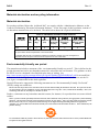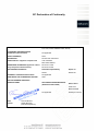
1
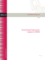
Flashlink User Manual
D422
RS-422 Data Transceiver
Supports CWDM
network-electronics.com
Rev. 6
D422
Rev. 6
Network Electronics AS
3230 Sandefjord, Norway
Phone: +47 33 48 99 99
Fax: +47 33 48 99 98
e-mail: [email protected]
www.network-electronics.com
Direct Service Phone: +47 90 60 99 99
Revision history
The latest version is always available in pdf-format on our web site:
http://www.network-electronics.com/
Current revision of this document is the uppermost in the table below.
Revision Replaces Date
Change Description
6
5
2008-07-24
Added Declaration of Conformity.
5
4
2007-10-24
New front page and removed old logo.
4
3
2007-10-05
Added Materials Declaration and EFUP
3
2
06.02.06
Updated CWDM laser options.
2
1
13.12.05
Added text in table (Chapter 4.2).
1
0
26.11.02
Added CWDM information
0
A
01.11.01
Final first release.
04.09.01
Preliminary version
A
2
D422
Rev. 6
Index
1. General......................................................................................................................................................4
2. Specifications............................................................................................................................................5
3. Connector module....................................................................................................................................6
3.1 Mounting the connector module. .........................................................................................................6
3.2 Connector Pin Assignments.................................................................................................................7
3.3 Line Termination .................................................................................................................................7
4. Module status ...........................................................................................................................................7
4.1 GPI – Module Status Outputs ..............................................................................................................8
4.2 Front Panel - Status Monitoring .........................................................................................................9
5. Laser safety precautions........................................................................................................................10
General environmental requirements for flashlink® equipment ..........................................................11
Product Warranty .....................................................................................................................................12
Materials declaration and recycling information ...................................................................................13
Materials declaration ................................................................................................................................13
Environmentally-friendly use period.......................................................................................................13
Recycling information ...............................................................................................................................14
EC Declaration of Conformity .................................................................................................................15
3
D422
Rev. 6
1. General
Figure 2. D422 – RS-422 Data Transceiver Block Diagram
The flashlink D422 module provides an economical solution for transmitting RS-422 data signals via
fiber optic cable. A pair of D422 allows bi-directional transmission of RS-422 data for distances over
60km. When access to fiber is limited, D422 can be combined with the flashlink optical multiplexing
WDM, CWDM or DWDM products.
As stand alone unit, the D422 module utilises 2 fiber strands for bi-directional data transport. Using either
2 fiber strands or optical multiplexing technology guarantees minimum possible latency for applications
where timing is crucial. The D422 module is supplied together with the D422-C1 connector module.
The optical output is made with a Fabry-Perot laser diode for 1310±40nm or a DFB laser for 1550±40nm
and the CWDM wavelengths according to ITU-T G.694 from 1270±6nm up to 1610±6nm.
The product is available in the following versions:
D422-13T -7.5dBm
D422-13T 0 dBm
D422-15T 0 dBm
D422-C1470
D422-C1490
D422-C1510
D422-C1530
D422-C1550
D422-C1570
D422-C1590
D422-C1610
1310± 40nm -7.5 dBm F-P laser
1310± 40nm 0 dBm F-P laser
1550± 40nm 0 dBm DFB laser
CWDM (DFB lasers)
D422-C1270
1470± 6nm 0dBm
D422-C1290
1490± 6nm 0dBm
D422-C1310
1510± 6nm 0dBm
D422-C1330
1530± 6nm 0dBm
D422-C1350
1550± 6nm 0dBm
D422-C1370
1570± 6nm 0dBm
D422-C1390
1590± 6nm 0dBm
D422-C1410
1610± 6nm 0dBm
1270± 6nm 0dBm
1290± 6nm 0dBm
1310± 6nm 0dBm
1330± 6nm 0dBm
1350± 6nm 0dBm
1370± 6nm 0dBm
1390± 6nm 0dBm
1410± 6nm 0dBm
4
D422
Rev. 6
2. Specifications
Data inputs and outputs
Signal format:
Connector:
Bit Rate:
Latency:
Electrical
Voltage:
Power:
Control:
RS-422
RJ-45
DC up to 115.2 kbps
400ns maximum single direction latency including 1m of fiber.
Additional latency 5μs/km of fiber.
+5V DC
2.4 Watts
RS-422 with protocol for use with GYDA System Controller.
Control system has access to set-up and module status with BITE
(Built-In Test Equipment).
Optical
Optical Input
Sensitivity:
Max. input power:
Optical wavelengths:
Transmission circuit fiber:
Return loss:
Connector:
better than –30dBm
-3dBm
1310nm, 1550nm
Multi Mode 50/125μm, Single Mode 9/125μm compatible
> 26dB
SC/UPC, Return Loss better than 40dB
Optical Output
Transmission circuit fiber:
Light source:
Optical wavelength (ver. 13T):
Optical power:
Optical power (option):
Optical wavelength (ver. 15T):
Single Mode
F-P/DFB Laser
1310nm ± 40nm
-7.5 dBm
0 dBm
1550nm ± 40nm
Optical power (option):
Optical wavelength for CWDM:
Optical power for CWDM
modules:
Jitter (UI=unit interval):
Connector return loss:
Maximum reflected power:
Connector:
0 dBm
1270, 1290, 1310, 1330, 1350, 1370, 1390, 1410,
1470, 1490, 1510, 1530, 1550, 1570, 1590 or 1610 ±6nm according
to ITU-T G.694.2
0 dBm
0.135 UI max.
better than 40 dB typ.
4%
SC/UPC
5
D422
Rev. 6
3. Connector module
The D422 has a dedicated connector module: D422-C1. This module is mounted at the rear of the subrack. The module is shown in figure 2.
To set up a link, two D422 modules must be used. The RS-422 data cable is connected to RS422/E1 on
each of the D422 modules. The two modules are connected to the fibres with one fiber from TX on
module 1 to RX on module 2, and from RX on module 1 to TX on module 2.
The TX UPG connector contains an electrical version of the modulated signal running on the fiber. This
connector is used for future upgrade with a flashlink multichannel DWDM system.
The connector marked E2 is not in use with the D422 module.
Figure 2. Overview of the D422-C1 connector module
3.1 Mounting the connector module.
This section only applies if the module is not purchased pre-mounted in a sub-rack.
The details of how the connector module is mounted, is found in the user manual for the sub-rack frame
FR-2RU-10-2.
This manual is also available from our web site: http://www.network-electronics.com/
6
D422
Rev. 6
3.2 Connector Pin Assignments
RS-422 shall be connected to the RS422/E1 connector, positioned as shown in figure 2. The connector is
a RJ-45, 8-pin type.
RS-422 pin layout:
Signal Name
RX +
Receive Data Positive
RX Receive Data Negative
TX +
Transmit Data Positive
TX Transmit Data Negative
Pin #
Pin 1
Pin 2
Pin 3
Pin 6
Mode
Input
Input
Output
Output
Figure 3: RS-422 Outlet
3.3 Line Termination
At the end of a RS-422 bus, the line must be terminated with a resistor. With RS-422 lines this is
typically done at the receiver side with a 120 ohm resistor.
The D422 module has a built in 120 ohm resistor at the receiver input terminal. The transmitter output
terminal has no line terminating resistors.
4. Module status
The status of the module can be monitored in three ways.
1. GYDA System Controller.
2. GPI at the rear of the sub-rack.
3. LED’s at the front of the sub-rack.
Of these three, the GPI and the LED’s are mounted on the module itself, whereas the GYDA System
Controller is a separate module giving detailed information of the status of the card. The functions of the
GPI and the LED’s are described in sections 4.1 and 4.2. The GYDA controller is described in a separate
user manual.
7
D422
Rev. 6
4.1 GPI – Module Status Outputs
These outputs can be used for wiring up alarms for third party control systems. The GPI outputs are open
collector outputs, sinking to ground when an alarm is triggered. The GPI connector is shown in figure 2.
Electrical Maximums for GPI outputs
Max current: 100mA
Max voltage: 30V
D422 module GPI pin layout:
Signal
Name
Status
General error status for the module.
LOS
Los Of optical input Signal
Laser Fail Laser Fail Alarm
Ground
0 volt pin
Pin #
Pin 1
Pin 2
Pin 3
Pin 8
Mode
Open Collector
Open Collector
Open Collector
0V.
Figure 3: GPI Outlet
8
D422
Rev. 6
4.2 Front Panel - Status Monitoring
The status of the module can be easily monitored visually by the LED’s at the front of the module. The
LED’s are visible through the front panel as shown in figure 4 on the next page.
(Text not printed on the front panel).
Figure 4. Front panel indicator overview for D422-13T/15T
The D422 has 3 LED’s each showing a status corresponding to the GPI pin layout. The position of the
different LED’s is shown in figure 4.
Diode \ state
Status
LOS
Laser fail
Red LED
Module is faulty or
Laser is turned off by
GYDA
Loss of signal
No optical input signal.
Laser is malfunctioning
Green LED
Module is OK
Module power is OK
No light
Module has no
power
Optical input signal
present
Laser is OK
9
D422
Rev. 6
5. Laser safety precautions
Guidelines to limit hazards from laser exposure.
All the available EO units in the flashlink® range include a laser.
Therefore this note on laser safety should be read thoroughly.
The lasers emit light at wavelengths around 1310 nm or 1550 nm. This means that the human eye cannot
see the beam, and the blink reflex cannot protect the eye. (The human eye can see light between 400 nm
to 700 nm).
A laser beam can be harmful to the human eye (depending on laser power and exposure time). Therefore:
!! BE CAREFUL WHEN CONNECTING / DISCONNECTING FIBER PIGTAILS (ENDS).
NEVER LOOK DIRECTLY INTO THE PIGTAIL OF THE LASER/FIBER.
NEVER USE MICROSCOPES, MAGNIFYING GLASSES OR EYE LOUPES TO LOOK INTO A
FIBER END.
USE LASER SAFETY GOGGLES BLOCKING LIGHT AT 1310 nm AND AT 1550 nm
Instruments exist to verify light output power: Power meters, IR-cards etc.
flashlink® features:
All the laser module cards in the flashlink® product range, are Class 1 laser products according to
IEC 825-1 1993, and class I according to 21 CFR 1040.10 when used in normal operation.
More details can be found in the user manual for the FR-2RU-10-2 frame.
Maximum output power*: 5 mW.
Operating wavelengths: > 1270 nm.
*
Max power is for safety analysis only and does not represent device performance.
10
D422
Rev. 6
General environmental requirements for flashlink® equipment
1. The equipment will meet the guaranteed performance specification under the following environmental
conditions:
•
•
Operating room temperature range
Operating relative humidity range
0°C to 50°C
up to 90% (non-condensing)
2. The equipment will operate without damage under the following environmental conditions:
•
•
Temperature range
Relative humidity range
-10°C to 55°C
up to 95% (non-condensing)
11
D422
Rev. 6
Product Warranty
The warranty terms and conditions for the product(s) covered by this manual follow the General Sales
Conditions by Network Electronics AS. These conditions are available on the company web site of
Network Electronics AS:
www.network-electronics.com
12
D422
Rev. 6
Materials declaration and recycling information
Materials declaration
For product sold into China after 1st March 2007, we comply with the “Administrative Measure on the
Control of Pollution by Electronic Information Products”. In the first stage of this legislation, content of
six hazardous materials has to be declared. The table below shows the required information.
Toxic or hazardous substances and elements
組成名稱
Part Name
D422
鉛
汞
镉
六价铬
多溴联苯
多溴二苯醚
Lead Mercury Cadmium Hexavalent Polybrominated Polybrominated
(Pb)
(Hg)
(Cd)
Chromium
biphenyls
diphenyl ethers
(Cr(VI))
(PBB)
(PBDE)
X
O
O
O
O
O
O: Indicates that this toxic or hazardous substance contained in all of the homogeneous materials for
this part is below the limit requirement in SJ/T11363-2006.
X: Indicates that this toxic or hazardous substance contained in at least one of the homogeneous
materials used for this part is above the limit requirement in SJ/T11363-2006.
Environmentally-friendly use period
The manual must include a statement of the “environmentally friendly use period”. This is defined as the
period of normal use before any hazardous material is released to the environment. The guidance on how
the EFUP is to be calculated is not finalised at the time of writing. See
http://www.aeanet.org/GovernmentAffairs/qfLeOpAaZXaMxqGjSFbEidSdPNtpT.pdf for an unofficial
translation of the draft guidance. For our own products, Network Electronics has chosen to use the 50
year figure recommended in this draft regulation.
Network Electronics suggests the following statement on An “Environmentally Friendly Use Period”
(EFUP) setting out normal use:
EFUP is the time the product can be used in normal service life without leaking the hazardous materials. We expect the normal
use environment to be in an equipment room at controlled temperature range (0ºC - 40ºC) with moderate humidity (< 90%, noncondensing) and clean air, not subject to vibration or shock.
Further, a statement on any hazardous material content, for instance, for a product that uses some tin/lead
solders:
Where a product contains potentially hazardous materials, this is indicated on the product by the appropriate symbol containing
the EFUP. The hazardous material content is limited to lead (Pb) in some solders. This is extremely stable in normal use and the
EFUP is taken as 50 years, by comparison with the EFUP given for Digital Exchange/Switching Platform in equipment in
Appendix A of “General Rule of Environment-Friendly Use Period of Electronic Information Products”. This is indicated by the
product marking:
50
It is assumed that while the product is in normal use, any batteries associated with real-time clocks or battery-backed RAM will
be replaced at the regular intervals.
13
D422
Rev. 6
The EFUP relates only to the environmental impact of the product in normal use, it does not imply that the product will
continue to be supported for 50 years.
Recycling information
Network Electronics provides assistance to customers and recyclers through our web site
http://www.network-electronics.com. Please contact Network Electronics’ Customer Support for
assistance with recycling if this site does not show the information you require.
Where it is not possible to return the product to Network Electronics or its agents for recycling, the
following general information may be of assistance:
Before attempting disassembly, ensure the product is completely disconnected from power and signal
connections.
All major parts are marked or labelled to show their material content.
Depending on the date of manufacture, this product may contain lead in solder.
Some circuit boards may contain battery-backed memory devices.
14
D422
Rev. 6
EC Declaration of Conformity
Network Electronics AS
P.B. 1020, N-3204 SANDEFJORD, Norway
MANUFACTURER
AUTHORISED REPRESENTATIVE
(Established within the EEA)
Not applicable
MODEL NUMBER(S)
D422
DESCRIPTION
RS-422 Data Transceiver
DIRECTIVES this equipment complies with
LVD 73/23/EEC
EMC 2004/108/EEC
HARMONISED STANDARDS applied in order to
verify compliance with Directive(s)
EN 55103-1:1996
EN 55103-2:1996
TEST REPORTS ISSUED BY
Notified/Competent Body
Report no:
Nemko
E08462.00
TECHNICAL CONSTRUCTION FILE NO
Not applicable
YEAR WHICH THE CE-MARK WAS AFFIXED
2008
TEST AUTHORIZED SIGNATORY
MANUFACTURER
AUTHORISED REPRESENTATIVE
(Established within EEA)
Date of Issue
2008-07-24
Place of Issue
Not applicable
Name
Thomas Øhrbom
Position
Quality Manager
(authorised signature)
Sandefjord, Norway
15