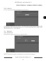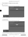
1
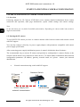
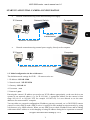
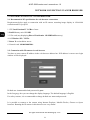
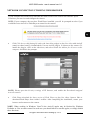
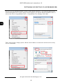
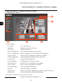
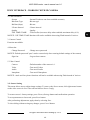
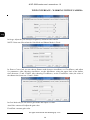
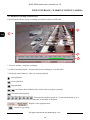
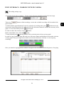
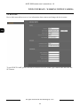
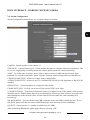
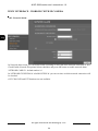
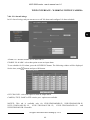
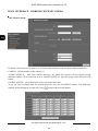
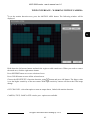
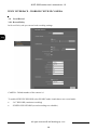
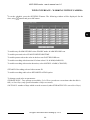
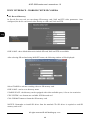
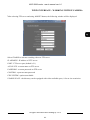
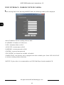
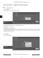
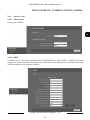
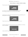
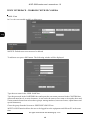
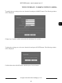
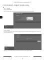
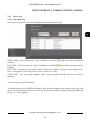
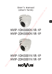
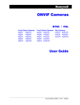
U s e r ’s m a n u a l NVIP-5000 series IP camera NVIP-5000 series user’s manual ver.1.0 IMPORTANT SAFEGUARDS AND WARNINGS EMC (2004/108/EC) and LVD (2006/95/EC ) Directives CE Marking Our products are manufactured to comply with requirements of the following directives and national regulations implementing the directives: Electromagnetic compatibility EMC 2004/108/EC. Low voltage LVD 2006/95/EC with further amendment. The Directive applies to electrical equipment designed for use with a voltage rating of between 50VAC and 1000VAC as well as 75VDC and 1500VDC. WEEE Directive 2002/96/EC Information on Disposal for Users of Waste Electrical and Electronic Equipment This appliance is marked according to the European 1000VAC Directive on Waste Electrical and Electronic Equipment (2002/96/EC) and further amendments. By ensuring this product is disposed of correctly, you will help to prevent potential negative consequences for the environment and human health, which could otherwise be caused by inappropriate waste handling of this product. The symbol on the product, or the documents accompanying the product, indicates that this appliance may not be treated as household waste. It shall be handed over to the applicable collection point for used up electrical and electronic equipment for recycling purpose. For more information about recycling of this product, please contact your local authorities, your household waste disposal service or the shop where you purchased the product. RoHS Directive 2002/95/EC Out of concern for human health protection and friendly environment, we assure that our products falling under RoHS Directive regulations, regarding the restriction of the use of hazardous substances in electrical and electronic equipment, have been designed and manufactured in compliance with the above mentioned regulations. Simultaneously, we claim that our products have been tested and do not contain hazardous substances whose exceeding limits could have negative impact on human health or natural environment Information The device, as a part of professional CCTV system used for surveillance and control, is not designed for self installation in households by individuals without technical knowledge. Excluding of responsibility in case of damaging data on a disk or other devices: The manufacturer does not bear any responsibility in case of damaging or losing data on a disk or other devices during device operation. WARNING! PRIOR TO UNDERTAKING ANY ACTION THAT IS NOT DESCRIBED FOR THE GIVEN PRODUCT IN USER’S MANUAL AND OTHER DOCUMENTS DELIVERED WITH THE PRODUCT, OR IF IT DOES NOT ARISE FROM THE USUAL APPLICATION OF THE PRODUCT, MANUFACTURER MUST BE CONTACTED UNDER THE RIGOR OF EXCLUDING THE MANUFACTURER’S RESPONSIBILITY FOR THE RESULTS OF SUCH AN ACTION. All rights reserved © AAT Holding sp. z o.o. 2 NVIP-5000 series user’s manual ver.1.0 IMPORTANT SAFEGUARDS AND WARNINGS WARNING! THE KNOWLEDGE OF THIS MANUAL IS AN INDISPENSIBLE CONDITION OF A PROPER DEVICE OPERATION. YOU ARE KINDLY REQEUSTED TO FAMILIARIZE YOURSELF WITH THE MANUAL PRIOR TO INSTALLATION AND FURTHER DEVICE OPERATION. WARNING! USER IS NOT ALLOWED TO DISASSEMBLE THE CASING AS THERE ARE NO USER -SERVICEABLE PARTS INSIDE THIS UNIT. ONLY AUTHORIZED SERVICE PERSONNEL MAY OPEN THE UNIT INSTALLATION AND SERVICING SHOULD ONLY BE DONE BY QUALIFIED SERVICE PERSONNEL AND SHOULD CONFORM TO ALL LOCAL REGULATIONS 1. Prior to undertaking any action please consult the following manual and read all the safety and operating instructions before starting the device. 2. Please keep this manual for the lifespan of the device in case referring to the contents of this manual is necessary; 3. All the safety precautions referred to in this manual should be strictly followed, as they have a direct influence on user’s safety and durability and reliability of the device; 4. All actions conducted by the servicemen and users must be accomplished in accordance with the user’s manual; 5. The device should be disconnected from power sources during maintenance procedures; 6. Usage of additional devices and components neither provided nor recommended by the producer is forbidden; 7. You are not allowed to use the camera in high humidity environment (i.e. close to swimming pools, bath tubs, damp basements); 8. Mounting the device in places where proper ventilation cannot be provided (e. g. closed lockers etc.) is not recommended since it may lead to heat build-up and damaging the device itself as a consequence; 9. Mounting the camera on unstable surface or using not recommended mounts is forbidden. Improperly mounted camera may cause a fatal accident or may be seriously damaged itself. The camera must be mounted by qualified personnel with proper authorization, in accordance with this user’s manual. 10. Device should be supplied only from a power sources whose parameters are in accordance with those specified by the producer in the camera technical datasheet. Therefore, it is forbidden to supply the camera from a power sources with unknown parameters, unstable or not meeting producer’s requirements; Due to the product being constantly enhanced and optimized, certain parameters and functions described in the manual in question may change without further notice. We strongly suggest visiting the www.novuscctv.com website in order to access the newest manual Data included in the following user’s manual is up to date at the time of printing. AAT Holding Sp z o.o. holds exclusive rights to modify this manual. The producer reserves the rights for device specification modification and change in the design without prior notice. All rights reserved © AAT Holding sp. z o.o. 3 NVIP-5000 series user’s manual ver.1.0 TABLE OF CONTENTS TABLE OF CONTENTS ..................................................................................................... 4 1. START-UP AND INITIAL IP CAMERA CONFIGURATION ................................. 6 1.1. Overview............................................................................................................... 6 1.2. Starting the IP camera ........................................................................................... 6 1.3. Initial configuration via the Web browser ............................................................. 7 2. NETWORK CONNECTION UTILIZING WEB BROSWER .................................. 8 2.1. Recommended PC specification for web browser ................................................ 8 2.2. Initial configuration via the Web browser ........................................................... 8 3. WWW INTERFACE - WORKING WITH IP CAMERA ......................................... 12 3.1. Displaying live pictures. ..................................................................................... 12 3.2. Sensor Setting. .................................................................................................... 13 3.3. Playback recordings from SD card. .................................................................... 20 3.4. Device Info. ........................................................................................................ 22 3.5. Stream Configuration. ........................................................................................ 23 3.6. Device Configuration. ........................................................................................ 24 3.6.1. Local Network. ...................................................................................... 24 3.6.2. Device Port. ........................................................................................... 25 3.6.3 ADSL Network. ..................................................................................... 26 3.6.4. Camera. ................................................................................................. 26 3.6.5. Date. ...................................................................................................... 27 3.6.6. OSD. ...................................................................................................... 28 3.6.7. Microphone. .......................................................................................... 29 3.6.8. Dome PTZ. ............................................................................................ 29 3.6.9. BNC Output........................................................................................... 30 3.6.10. System Configuration. ......................................................................... 30 3.7. External Device. ............................................................................................................ 31 3.7.1. PTZ. ................................................................................................. 31 3.7.2. PTZ Keyboard. ................................................................................ 31 3.8. Alarm Configuration. .................................................................................................... 32 3.8.1. Alarm I/O. ....................................................................................... 32 3.8.2. Disk Alarm Linkage........................................................................ 33 3.8.3. Network Alarm ............................................................................... 34 All rights reserved © AAT Holding sp. z o.o. 4 NVIP-5000 series user’s manual ver.1.0 FOREWORD INFORMATION 3.8.4. I/O Alarm Linkage. ............................................................................. 35 3.8.5. Alarm Setting. ..................................................................................... 36 3.9. Local Record. ..................................................................................................... 38 3.9.1. Record Policy. ................................................................................ 38 3.9.2. Record Directory. ........................................................................... 40 3.10 Privacy Masking. .............................................................................................. 43 3.11. Network Service............................................................................................... 44 3.11.1. PPPoE. .......................................................................................... 44 3.11.2. DDNS. .......................................................................................... 44 3.12. Service Center. ................................................................................................. 45 3.12.1. Alarm Center. ............................................................................... 45 3.12.2. SMTP............................................................................................ 45 3.13. Privilege Manager. ........................................................................................... 46 3.13.1. Group. ........................................................................................... 46 3.13.2. User. ............................................................................................. 48 3.14. Protocol. ........................................................................................................... 50 3.14.1. Protocol Info. ................................................................................ 50 3.14.2. Security. ........................................................................................ 50 3.15. Device Log. ...................................................................................................... 51 3.15.1. Operation Log. .............................................................................. 51 3.15.2. Alarm Log. .................................................................................. 52 3.15.3. Collect Log. .................................................................................. 53 3.16. Maintenance. .................................................................................................... 53 3.16.1. System Service. ................................................................................. 53 3.16.2. Device Restart. .................................................................................. 54 3.16.3. Default Settings. ................................................................................ 54 All rights reserved © AAT Holding sp. z o.o. 5 NVIP-5000 series user’s manual ver.1.0 START-UP AND INITIAL CAMERA CONFIGURATION 1. START-UP AND INITIAL IP CAMERA CONFIGURATION 1.1. Overview Following manual for IP Cameras NVIP-5000 series contains detailed information about camera connection and operation, main page introduction, system related settings and camera settings. Note In this document you can find all available functionality. Depending on camera model some features might be unavailable. 1.2. Starting the IP camera To run NOVUS IP camera you have to connect ethernet cable between camera and network switch with PoE support. You can also connect it directly via power supply adapter with parameters compatible with camera power supply specification. After connecting power supply initialization process is started, which takes about 2 minutes. The recommended way to start an IP camera and perform its configuration is connect directly to the network switch which is not connected to other devices. To obtain further information about network configuration parameters (IP address, gateway, network mask, etc.) please contact your network administrator. Network connection using switch with PoE support. IP Camera Network Switch PoE Power supply and network transmission Network transmission All rights reserved © AAT Holding sp. z o.o. 6 Computer NVIP-5000 series user’s manual ver.1.0 START-UP AND INITIAL CAMERA CONFIGURATION Network connection using switch and external power supply. IP Camera Network Switch Computer Network transmission Network transmission Network connection using external power supply, directly to the computer. IP Camera Computer Network transmission - cross over cable 1.3. Initial configuration via the web browser The default network settings for NVIP-… IP camera series are : 1. IP address= 192.168.1.200 2. Network mask - 255.255.255.0 3. Gateway - 192.168.1.1 4. User name - root 5. Password - pass Knowing the camera’s IP address you need to set PC IP address appropriately, so the two devices can operate in one network subnet ( e.g. for IP 192.168.1.1, appropriate address for the camera is from range 192.168.1.2 to 192.168.1.254, for example 192.168.1.60). It is not allowed to set the same addresses for camera and PC computer You can either set a network configuration (IP address, gateway, net mask, etc.) of NOVUS IP camera yourself or select DHCP mode (DHCP server is required in this method in target network) by using web browser or by NMS software. When you use DHCP server check IP address lease and its linking with camera MAC address to avoid changing or losing IP address during device operation or network/ All rights reserved © AAT Holding sp. z o.o. 7 NVIP-5000 series user’s manual ver.1.0 NETWORK CONNECTION VIA WEB BROWSER 2. NETWORK CONNECTION VIA WEB BROSWER 2.1. Recommended PC specification for web browser connections Requirements below apply to connection with an IP camera, assuming image display in 1920x1080 resolution and 25 fps speed. 1. CPU Intel Pentium IV 3 GHz or faster 2. RAM Memory min. 512 MB 3. VGA card (any displaying Direct 3D with min. 128 MB RAM memory) 4. OS Windows XP / VISTA 5. Direct X version 9.0 or newer 6. Network card 10/100/1000 Mb/s 2.2. Connection with IP camera via web browser You have to enter camera IP address in the web browser address bar. If IP address is correct user login window will be displayed: Default user is root and default password is pass. In the Language box you can change the display language. The default language is English. For safety reasons, it is recommended to change default user name and password. It is possible to connect to the camera using Internet Explorer, Mozilla Firefox, Chrome or Opera browsers. Running the IP camera in this browsers are very similar. All rights reserved © AAT Holding sp. z o.o. 8 NVIP-5000 series user’s manual ver.1.0 NETWORK CONNECTION UTILIZING WEB BROWSER If your computer has Flash Player installed, the main screen for the camera web interface opens. From here you can view and configure the camera. NOTE: If your computer does not have Flash Player installed, you will be prompted to select if you would like to use ActiveX or Flash Player to connect to the camera: Click Click here to shift playing life video with short delay widget! to play live video with ActiveX control to reduce latency (recommended): Uses an ActiveX plug-in to connect to the camera. To install the plug-in, click on the video area, and select Install this Add-on for all users on this computer, and follow the prompts. NOTE: Please open the Security settings of IE browser, and enable the Download unsigned ActiveX controls. Click Please download the latest version of Flash Player to play live video: Opens a link to download Flash Player from Adobe’s website. After completing the installation, restart your browser and reconnect to the camera. NOTE: When working in Windows Vista/7/8 the ActiveX applet may be blocked by Windows Defender or User account control. In such case you should allow to run this applet, or simply disable these functions. All rights reserved © AAT Holding sp. z o.o. 9 NVIP-5000 series user’s manual ver.1.0 NETWORK CONNECTION VIA WEB BROWSER NOTE: If you are running Windows Vista/7/8 with Internet Explorer 11, the ActiveX applet can be blocked through browser security settings. In this situation, you should: add the IP address of the camera to the view of compatibility (Tools -> Compatibility View Settings, click Add). Then, in the security settings options, add the camera address to trusted sites and lower the security level to a minimum. All rights reserved © AAT Holding sp. z o.o. 10 NVIP-5000 series user’s manual ver.1.0 NETWORK CONNECTION UTILIZING WEB BROWSER After making the changes, restart the browser, re-connect to the camera and log on. All rights reserved © AAT Holding sp. z o.o. 11 NVIP-5000 series user’s manual ver.1.0 WWW INTERFACE - WORKING WITH IP CAMERA 3. WWW INTERFACE - WORKING WITH IP CAMERA 3.1. Displaying live pictures 4. 3. 1. 2. 5. 1.Camera settings Live Video - Live video preview Playback* - Playback records form SD card Device Info - Device information Stream Configuration - Video and audio settings for each stream Device Configuration - Device configuration (e.g. Local Network, Date&Time) External Device - External device configuration (function unavailable) Alarm Configuration - Alarm Configuration (Motion alarm, Alarm I/O) Local Record - Local Record Configuration Privacy Masking - Configuration up to 5 privacy masks Network Service - Network services configuration (e.g. DDNS) Service Center - Service center configuration (e.g. SMTP) Privilege Manager - Users and groups management Protocol - Protocols settings (e.g. ONVIF) Device Log - Device Log contains: Operation Log, Alarm Log and Collect Log Maintenance - Device Restart and restoring Default Settings *This option is available when using Internet Explorer All rights reserved © AAT Holding sp. z o.o. 12 NVIP-5000 series user’s manual ver.1.0 WWW INTERFACE - WORKING WITH IP CAMERA 2. Video Parameter Stream - Stream ID (choose one from available streams) Bite Rate Type - Bit rate type Bit Rate (kbps) - Bit rate I Frame Interval - I frame interval Quality - Quality USE TIME STAMP - Video buffer (increases delay when enabled, maximum delay is 5s) NOTICE: USE TIME STAMP function will not be available when using Flash instead of Activex. 3. Camera Control Function unavailable. 4. Menu bar Change Password - Change users password NOTICE: Default password "pass" can be restored only after restoring default settings of the camera) Sign Out - Log out from camera 5. Video Control Camera - Default number of the camera is 1. Video - Turn on/off video Audio - Turn on/off audio Interphone - Turn on/off Interphone NOTICE: Audio and Interphone functions will not be available when using Flash instead of Activex. 3.2. Sensor Setting This menu allows user to adjust image settings. To enter to the Sensor menu, click right mouse button on the video screen in Live Video tab and choose Sensor Config. To restore sensor’s factory settings, press FactorySettings button and confirm that operation. To reset parameters to last saved, press Reset button. After performing adjustments, apply them by selecting Save. To close dialog without saving any changes, press Cancel button. All rights reserved © AAT Holding sp. z o.o. 13 NVIP-5000 series user’s manual ver.1.0 WWW INTERFACE - WORKING WITH IP CAMERA In Image Adjust tab you can adjust brightness, saturation and contrast. NOTE: It has not effect when the Gain Mode and Shutter Mode is Fixed. In Shutter Control tab you can choose Shutter mode between AutoShutter or FixedShutter and adjust it’s parameters. After choosing AutoShutter, set the MaxShutter value (the upper limit of the shutter time) between 1/5 and 1/50000. After choosing FixedShutter, set the FixedShutter value (the value of the shutter time) between 1/5 and 1/50000. In Gain Mode tab you can choose gain mode and adjust it’s value. AutoGain: camera will adjust the gain value. FixedGain: constant gain value. All rights reserved © AAT Holding sp. z o.o. 14 NVIP-5000 series user’s manual ver.1.0 WWW INTERFACE - WORKING WITH IP CAMERA In DayNightMode tab you can choose how the camera toggles between Day mode and Night mode. Set Auto to let the camera control that function automatically. Use Delay(s) bar to select time for delay switch between day and night mode. Set DayMode to turn on day mode permanently. Set NightMode to turn on night mode permanently. Timing Mode allows you to select the times for switching form DayToNight Time mode or NightToDay Time mode. NOTICE: This tab is not available for NVIP-2DN5000D/IR-1P, NVIP-2DN5040V/IR-1P, NVIP3DN5000D/IR-1P, NVIP-3DN5040V/IR-1P, NVIP-5DN5000D/IR-1P, NVIP-5DN5040V/IR-1P models. In Auto Iris tab you can adjust Auto Iris function. In Auto Iris box, you can turn on Auto Iris function (set the value to ON) or turn off the Auto Iris function (set the value to OFF). IrisSpeed slider allows to set speed of the auto iris mechanism. Indoor/Outdoor Mode box allows to choose Indoor or Outdoor operating environment. All rights reserved © AAT Holding sp. z o.o. 15 NVIP-5000 series user’s manual ver.1.0 WWW INTERFACE - WORKING WITH IP CAMERA In WDR tab you can turn on or off WDR function. That function is available only in 3 MPx cameras. NOTICE: If you turn on WDR function, DSS will not work (available range of MaxShutter value will be between 1/25 and 1/50000)! In GAMMA tab you can choose gamma mode. Five modes are available: Standard, High, Middle, Low, Dynamic. All rights reserved © AAT Holding sp. z o.o. 16 NVIP-5000 series user’s manual ver.1.0 WWW INTERFACE - WORKING WITH IP CAMERA In AE Meter Mode tab you can choose meter mode for AE function. Four modes are available: Multi-Pattern - whole area is metered symmetrically with the same percentage. Center-Weighted - the center area (1/5 occupied) with priority to be weighted and then decrease outward gradually. Vertical Center-Weighted - the Vertical Center area (1/2 occupied) with priority to be weighted whole other areas with minimum weighted. Horizontal Center-Weighted - the Horizontal Center area (1/2 occupied) with priority to be weighted whole other areas with minimum weighted. In WB Setting tab you can adjust white balance function parameters. Set Auto in WB Mode box to let the camera control this function automatically. Set Manual in WB Mode box to adjust white balance parameters manually. All rights reserved © AAT Holding sp. z o.o. 17 NVIP-5000 series user’s manual ver.1.0 WWW INTERFACE - WORKING WITH IP CAMERA If WB Mode is set to Manual, choose it’s operating mode in Manual Mode box. Six modes for different operating environment are available: Overcast, Sunshine, Fluorescent light, Tungsten light, Lock the value and Customized. If Manual Mode is set to Lock the value, camera will save color values for actual scene and set it permanently. If Manual Mode is set to Customized, you can adjust RedGain and BlueGain parameters manually. In Mirror tab you can turn on mirror mode and choose it’s type from CLOSE, Horizontal, Vertical, PictureFlip. All rights reserved © AAT Holding sp. z o.o. 18 NVIP-5000 series user’s manual ver.1.0 WWW INTERFACE - WORKING WITH IP CAMERA In Noise Filter tab you can adjust settings for the noise filter function. Set Mode to Auto to let the camera control this function automatically and adjust Max Level value. Set Mode to Manual to be able to adjust more parameters of this function. NOTE: When values of Temporal and Spacial are 0, the Noise Filter will be off. Frame lost is possible when the Temporal value is more than 0. All rights reserved © AAT Holding sp. z o.o. 19 NVIP-5000 series user’s manual ver.1.0 WWW INTERFACE - WORKING WITH IP CAMERA 3.3. Playback recordings from SD card Playback menu allows to play recordings recorded by camera on SD card. 2 1 3 4 1. Preview window - displays recordings 2. Audio activations button - activates/deactivates listening to recorded audio 3. Playback control buttons - allows to control playback - Start playback - Pause playback - Stop playback - One frame forward/backward ( works when recording is paused ) - Fast backward playback - Selecting the playback speed of 1/16 normal playback up to 8 times the acceleration of playback - Displays video playback time - Capture to jpg image All rights reserved © AAT Holding sp. z o.o. 20 NVIP-5000 series user’s manual ver.1.0 WWW INTERFACE - WORKING WITH IP CAMERA - Recording settings copy 4. Selecting time for the recordings - To start search select the beginning and end for time range. Then press green colour. button to find recordings. At time bar available recordings will be marked with To make timeline approximations for precise selection of recording time, press and then move the cursor to the interesting point in the chart and click the left mouse button to increase the accuracy of the graph. To exit zoom mode press the button again. In order to reduce the accuracy use the Back to the default view, select the To start playback press button. button. and then double click on desired point of time on time graph. In order to copy recordings from SD cards press left mouse button and holding it down make selection on time graph. Then press right mouse button on selection and choose “Backup” to start copying recordings. Once you start the copying process window will appear with information about the process of copying All rights reserved © AAT Holding sp. z o.o. 21 NVIP-5000 series user’s manual ver.1.0 WWW INTERFACE - WORKING WITH IP CAMERA 3.4. Device Info Device Info menu allows user to view information about camera and change the device name. To set DEVICE NAME, please click the box next to DEVICE NAME, type camera name and click the SET button. All rights reserved © AAT Holding sp. z o.o. 22 NVIP-5000 series user’s manual ver.1.0 WWW INTERFACE - WORKING WITH IP CAMERA 3.5. Stream Configuration Stream Configuration menu allows user to adjust settings of streams. CAMERA - Default number of the camera is 1. STREAM ID - Camera features up to 2 video streams that may be configured and run individually. This let you set a high quality recording stream and a lower quality stream for remote monitoring. NAME - To set the name of stream, please click on the box next to NAME and type its name from keyboard. To clear the actual name, please click the X button, which will appear next to NAME box. VIDEO ENCODE TYPE - Allows to set base, main or high profile. AUDIO ENCODE TYPE - Allows to set G711 standard with ULAW/ALAW algorithms or RAW-PCM standard. RESOLUTION - Actual resolution of configured video stream. FRAME RATE (FPS) - for PAL can be up to 25fps and for NTSC up to 30fps. I FRAME INTERVAL - Time interval between I frames. For higher bit rate of the stream, frame spacing should be shorter. Smaller frame interval is recommended to increase position accuracy of return video and advantageous to the network video. If frame interval become small, the video streaming will become big. BIT RATE (KBPS) - You can choose from CBR (constant bit rate) and VBR (variable bit rate). To set BIT RATE, please click the box under CBR/VBR and type value between 500 and 12000kbps. QUALITY - Chose between 1-9 quality (available only for VBR) After performing adjustments, please apply them by selecting “OK”. All rights reserved © AAT Holding sp. z o.o. 23 NVIP-5000 series user’s manual ver.1.0 WWW INTERFACE - WORKING WITH IP CAMERA 3.6. Device Configuration 3.6.1. Local Network Local network menu allows user to set IP camera address, subnet mask, default gateway, DNS and other network parameters. In IP PROTOCOL box you can choose between IPv4 and IPv6 protocols, that will be used to set LAN IP address. To turn DHCP on, select the DEVICE OBTAIN IP ADDRESS AUTOMATICALLY option. In PREFERED DNS SERVER or ALTERNATE DNS SERVER you can manually enter address of DNS server. NOTE: Default MTU is 1500. Do not change MTU to more than 1500 for remote networks. All rights reserved © AAT Holding sp. z o.o. 24 NVIP-5000 series user’s manual ver.1.0 WWW INTERFACE - WORKING WITH IP CAMERA 3.6.2. Device Port Device Port menu allows user to change device port numbers. CONTROL PORT (the default is 30001) - for reading and writing settings, PTZ control, TCP audio and video port number. HTTP PORT (the default is 80) - for Web access to use the port number. If you change it to another port number, you need add “: port number” in the address bar at the end. For example, the equipment which IP is 192.168.1.200 and the Http port is changed to “8080”, you could enter the http://192.168.1.200:8080 in the internet browser's address bar to access the network device. RTSP PORT (the default is 554) is use for streaming video. Only requirement to change this is if you are using multiple devices on one IP which would require all ports to be modified. RTMP PORT (the default is 8080) for streaming audio, video and data over the Internet, between a Flash player and a server. All rights reserved © AAT Holding sp. z o.o. 25 NVIP-5000 series user’s manual ver.1.0 WWW INTERFACE - WORKING WITH IP CAMERA 3.6.3. ADSL Network ADSL Network menu shows the actual WAN network IP address. 3.6.4. Camera Camera menu allows user to change the channel name and video format. To set CHANNEL NAME, please click the box next to CHANNEL NAME, type any name and click the SET button. Name of the channel will be displayed in real-time monitoring. To change the video format, please choose 50Hz (PAL) or 60Hz (NTSC) in the VIDEO SYSTEM box and click the SET button. All rights reserved © AAT Holding sp. z o.o. 26 NVIP-5000 series user’s manual ver.1.0 WWW INTERFACE - WORKING WITH IP CAMERA 3.6.5. Date Date menu allows user to change time zone, daylight and date settings. Time zone can be changed in TIME ZONE box. Default time zone is: (GMT+01:00) Sarajevo, Skopje, Warsaw, Zagreb. To turn on daylight function, highlight ADJUST CLOCK FOR DAYLIGHT SAVING CHANGES option and set daylight settings. For START/END time of daylight changes, select: month - day of the month - day of the week - time DEVICE TIME box displays actual camera time. Select method to use to set the time: CURRENT PC TIME sets the time according to the clock on your computer. SET MANUALLY allows to manually enter the time and date. ENABLE NTP sets the time according to the clock on NTP server. To turn on NTP option highlight ENABLE NTP, type IP of the NTP server in NTP IP box and NTP PORT (default port is 123). All rights reserved © AAT Holding sp. z o.o. 27 NVIP-5000 series user’s manual ver.1.0 WWW INTERFACE - WORKING WITH IP CAMERA 3.6.6. OSD OSD menu allows user to set OSD parameters, for example which information will be displayed as overlay on encoded video steam. CAMERA - Default number of the camera is 1 OSD FONT SIZE - Font size of text on video stream TIME FORMAT - Choose one of available time format (default is: YYYY-MM-DD hh:mm:ss ww) Five options can be displayed as overlay on encoded video steam: DEVICE NAME, CHANNEL ID, CHANNEL NAME, PTZ POSITION, TIME. This information will be entered in the table with invisible lines. Select correct option and choose in which ROW and COLUMN it will be displayed. CUSTOM OSD option allows to write your own message on video stream. Select CUSTOM1-6 option, set RAW, COLUMN and write your own message in OSD column. All rights reserved © AAT Holding sp. z o.o. 28 NVIP-5000 series user’s manual ver.1.0 WWW INTERFACE - WORKING WITH IP CAMERA 3.6.7. Microphone MICROPHONE menu allows user to adjust microphone settings. CAMERA - Default number of the camera is 1 ENABLE MICROPHONE - Turn on/off the microphone MICROPHONE VOLUME - set microphone volume from 0 to 100 3.6.8. Dome PTZ Option not available. All rights reserved © AAT Holding sp. z o.o. 29 NVIP-5000 series user’s manual ver.1.0 WWW INTERFACE - WORKING WITH IP CAMERA 3.6.9. BNC Output BNC Output menu allows user to turn on or turn off the BNC output function. Set open to turn on the BNC output or set close to turn off the BNC output. 3.6.10. System Configuration In System Configuration menu you can set the actual language for screen OSD and alarm e-mail. To set the OSD language, please click on the box next to LANGUAGE SET and choose between English, Polish or Russian language. To enable communication encryption check Device Communication Encryption choose https in Web Mode and press SET button. All rights reserved © AAT Holding sp. z o.o. 30 NVIP-5000 series user’s manual ver.1.0 WWW INTERFACE - WORKING WITH IP CAMERA 3.7. External Device 3.7.1. PTZ Option not available. 3.7.2. PTZ Keyboard Option not available. All rights reserved © AAT Holding sp. z o.o. 31 NVIP-5000 series user’s manual ver.1.0 WWW INTERFACE - WORKING WITH IP CAMERA 3.8. Alarm Configuration 3.8.1. Alarm I/O In Alarm I/O menu you can set following alarm parameters: ALARM IN - Default number of alarm input ID is 1. NAME - to set the alarm input NAME, please click the box next to NAME and type any name from keyboard. VALID VOLTAGE LEVEL - high and low options are available. When you select high, normal input state is high (alarm signal is triggered when the voltage is lower than 12V), when you select low, normal input state is low (alarm signal is triggered with 12V voltage). ALARM OUT - Default number of alarm output ID is 1. NAME - to set the alarm output NAME, please click the box next to NAME and type any name from keyboard. VALID SIGNAL - close and open modes are available. When you select close, the alarm output is normally turned on. When you select open, the alarm output is normally turned off. ALARM OUT MODE - SWITCH MODE and PULSE MODE are available. When you select SWITCH MODE you can adjust only ALARM TIME. When you select PULSE MODE, set the ALARM TIME to 0 (save alarm state till frequency or alarm input change) and adjust FREQUENCY. FREQUENCY— time to change a state of the alarm output. ALARM TIME - output alarm duration. MANUAL CONTROL - press START or STOP button to change alarm out state. All rights reserved © AAT Holding sp. z o.o. 32 NVIP-5000 series user’s manual ver.1.0 WWW INTERFACE - WORKING WITH IP CAMERA NOTICE: Remember to turn on ENABLE I/O ALARM option (as well as set SCHELDULE) for alarm input and OUT CHANNEL option for alarm output in I/O Alarm Linkage tab (chapter 6.7.3.). Without that I/O alarms will not work. 3.8.2. Disk Alarm Linkage In Disk alarm Linkage menu you can adjust disk capability alarm and disk error alarm settings. If you want to turn on disk alarm, select the DISCK ALARM, and set the value next to DISK MAXIUM USE SPACE . Camera will generate an alarm when the disc will fill up to that value. ALARM INTERVAL defines the time at which disk usage will be checked. If you want to turn on disc error alarm, select DISC ALARM option. Disc alarm will be recorded in alarm log. OUTPUT and PTZ functions are not available. All rights reserved © AAT Holding sp. z o.o. 33 NVIP-5000 series user’s manual ver.1.0 WWW INTERFACE - WORKING WITH IP CAMERA 3.8.3. Network Alarm In Network alarm menu you can define alarm recording on SD card when network connection is lost. Check Enable Network Exceptional Alarm checkbox and press OK button to enable network alarm. NETWORK CARD ID - default number is 1 In NETWORK EXCEPTIONAL ALARM INTERVAL you can set time at which network connection will be checked. OUT CHANNEL and PTZ functions are not available. All rights reserved © AAT Holding sp. z o.o. 34 NVIP-5000 series user’s manual ver.1.0 WWW INTERFACE - WORKING WITH IP CAMERA 3.8.4. I/O Alarm Linkage In I/O Alarm Linkage tab you can turn on or off I/O alarm and configure I/O alarm schedule. ALARM I/O - Default number of I/O alarm ID is 1. ENABLE I/O ALARM - select that option to turn on input alarm. To set schedule for I/O alarm, press the SCHEDULE button. The following window will be displayed. Set the time, using buttons and press OK button. OUT CHANNEL - select that option to turn on output alarm. CAMERA, TYPE, NAME in PTZ window part - options not available. NOTICE: This tab is available only for NVIP-2DN5000D/IR-1P, NVIP-2DN5040V/IR-1P, NV IP -3DN5000D/ IR -1P , NVIP -3DN5040V/ IR -1P, NV IP-5DN5000D/ IR -1P and NVIP-5DN5040V/IR-1P models. All rights reserved © AAT Holding sp. z o.o. 35 NVIP-5000 series user’s manual ver.1.0 WWW INTERFACE - WORKING WITH IP CAMERA 3.8.5. Motion Alarm In Motion Alarm tab you can turn on or off motion alarm function and set motion alarm parameters. CAMERA - Default number of the camera is 1 ALARM INTERVAL - time after motion detection, for which the camera will not signal motion detection alarms. Click to the box next to ALARM INTERVAL, type the proper value and press OK button. ENABLE MOTION - select that option to turn on motion detection. To set the time of deployment for motion detection, press the SCHEDULE button. The following window will be displayed. Set the time, using buttons and press OK button. All rights reserved © AAT Holding sp. z o.o. 36 NVIP-5000 series user’s manual ver.1.0 WWW INTERFACE - WORKING WITH IP CAMERA To set the motion detection area, press the MOTION AREA button. The following window will be displayed. Hold down the left mouse button and mark the region to add a mask area. When you need to remove the mask area, click the right mouse button. Press REVERSE button to reverse selection of area. Press CLEAR button to erase all the selected areas. Choose the SENSITIVITY of motion detection, using button and press OK button. The bigger value is set the higher sensitivity of the movement. With high sensitivity camera will detect the least image change. OUT CHANNEL - select that option to turn on output alarm, linked with motion detection. CAMERA, TYPE, NAME in PTZ window part - options not available. All rights reserved © AAT Holding sp. z o.o. 37 NVIP-5000 series user’s manual ver.1.0 WWW INTERFACE - WORKING WITH IP CAMERA 3.9. Local Record 3.9.1. Record Policy In Record Policy tab you can set local recording settings. CAMERA - Default number of the camera is 1 To enable SCHDULE RECORD select ENABLE under it and choose one record mode: 24*7 RECORD (continous recording) SCHELDULE RECORD (record according to a schedule) All rights reserved © AAT Holding sp. z o.o. 38 NVIP-5000 series user’s manual ver.1.0 WWW INTERFACE - WORKING WITH IP CAMERA To set the schedule, press the SCHEDULE button. The following window will be displayed. Set the time, using buttons and press OK button. To enable any ALARM RECORD select ENABLE under ALARM RECORD text. To enable prerecord select ENABLE PRERECORDTIME. To enable postrecord set the value in the box near POST RECORD text. To enable recording after detection I/O alarm select I/O ALARM(ALARM IN). To enable recording after motion detection, select MOTION ALARM (CHANNEL). STEAM ID: Recording selected video stream ID. To enable recording audio select RECORDED AUDIO option. To change record rules set parameters: STORAGE RULE - Two options are available: Cycle Write (records are overwritten when the disk is full ) or Save Days (only specified number of days are stored). SAVE DAYS - number of days which records are stored (when STORAGE RULE is set to Save Days). All rights reserved © AAT Holding sp. z o.o. 39 NVIP-5000 series user’s manual ver.1.0 WWW INTERFACE - WORKING WITH IP CAMERA 3.9.2. Record Directory In Record Directory tab you can change SD memory card, NAS and FTP video parameters. Once configured, the device can record video directly to a SD card, NAS and FTP. DISK NAME - three default directories include SD card, NAS and FTP are available. After selecting SD card and using MODIFY button, the following window will be displayed: Select ENABLE to activate recording video on SD memory card. DISK NAME - can be set to directory name. USABLE SPACE - the directory can be equipped with video available space, 0 for no size restriction. FILE SYSTEM - two formats are available: SDVideo and ext3. Click FORMAT button to format the SD memory card. NOTICE: Remember to install SD driver from the attached CD. SD driver is required to read SD memory card on PC. All rights reserved © AAT Holding sp. z o.o. 40 NVIP-5000 series user’s manual ver.1.0 WWW INTERFACE - WORKING WITH IP CAMERA After selecting FTP server and using MODIFY button, the following window will be displayed: Select ENABLE to activate recording video on FTP server. IP ADDRESS - IP address of FTP server. PORT - FTP server port (default is 21) ACCOUNTS - account name on FTP server PASSWORD - account password on FTP server CONFIRM - repeat account password FILE SYSTEM - option unavailable USABLE SPACE - the directory can be equipped with video available space, 0 for no size restriction. All rights reserved © AAT Holding sp. z o.o. 41 NVIP-5000 series user’s manual ver.1.0 WWW INTERFACE - WORKING WITH IP CAMERA After selecting NAS server and using MODIFY button, the following window will be displayed: Select ENABLE to activate recording video on NAS. IP ADDRESS - IP address of NAS server. PATH - destination folder on NAS ACCOUNTS - account name on NAS PASSWORD - account password on NAS CONFIRM - repeat account password FILE SYSTEM - two formats are available: cifs and nfs USABLE SPACE - the directory can be equipped with video available space. Select USE ALL SPACE to activate recording without restrictions. NOTICE: To play video it is recommended to use NVIP-5000 Player from the attached CD. All rights reserved © AAT Holding sp. z o.o. 42 NVIP-5000 series user’s manual ver.1.0 WWW INTERFACE - WORKING WITH IP CAMERA 3.10. Privacy Masking In Privacy Masking tab you can set video covered area. The biggest support covered area is no more than 5% total image space. CAMERA - Default number of the camera is 1 Select ENABLE to activate private masking function. Hold down the left mouse button to mark the region to add a private mask. When you need to remove the mask area, click the right mouse button or RESET button. All rights reserved © AAT Holding sp. z o.o. 43 NVIP-5000 series user’s manual ver.1.0 WWW INTERFACE - WORKING WITH IP CAMERA 3.11. Network Service 3.11.1. PPPoE In PPPoE tab you can enable PPPoE function. Select ENABLE PPPOE to activate PPPoE WAN access. USERNAME - account name PASSWORD - account password Through the client software set up correctly PPPoE. Every time you start Network Camera, PPPoE mode automatically establish a network connection, after the success of the network camera to obtain the dynamic WAN IP address. 3.11.2. DDNS Function not available. All rights reserved © AAT Holding sp. z o.o. 44 NVIP-5000 series user’s manual ver.1.0 WWW INTERFACE - WORKING WITH IP CAMERA 3.12. Service Center 3.12.1. Alarm Center Function not available. 3.12.2. SMTP In SMTP tab you can enable, configure and test SMTP function. When SMTP is enabled, and event triggered by motion detection, alarm and/or I/O, alarm will be automatically sent with JPG picture and alarm information to the recipient's mailbox. All rights reserved © AAT Holding sp. z o.o. 45 NVIP-5000 series user’s manual ver.1.0 WWW INTERFACE - WORKING WITH IP CAMERA Select ENABLE SMTP to activate SMTP function. SMTP SERVER ADDRESS - sender server address SMTP SERVER PORT - sender server port (depends on chosen transport mode) USER NAME - sender e-mail account name PASSWORD - sender e-mail account password SENDER E-MAIL ADDRESS - full sender e-mail address (for example: [email protected]) RECIPIENT_E-MAIL_ADDRESS1- 5 - full recipient e-mail address (for example: [email protected]) ATTACHMENT IMAGE QUALITY - three modes are available: High, Mid, Low. Better image quality will increase the attachment size. TRANSPORT MODE - specifies the file encryption. Three modes are available: NO, SSL and STARTTLS. To check if the configuration is correct and the camera has connection to the internet press Send testMail button. 3.13. Privilege Manager 3.13.1. Group In Group tab you can add, modify or delete access groups. NOTICE: Default permissions group administrators can not to be deleted. All rights reserved © AAT Holding sp. z o.o. 46 NVIP-5000 series user’s manual ver.1.0 WWW INTERFACE - WORKING WITH IP CAMERA To add new group press ADD button. The following window will be displayed. Type a group name in the GROUP box, press OK button, and then Confirm button. Select created group from the list, choose any privileges and press OK button. To modify the name of existing group, select this group from the list and press MODIFY button. The following window will be displayed. Change the group name in the GROUP box, press OK button, and then Confirm button. To delete the existing group, select this group from the list and press DELETE button. The following window will be displayed. Confirm with DELETE button, then press Confirm button. All rights reserved © AAT Holding sp. z o.o. 47 NVIP-5000 series user’s manual ver.1.0 WWW INTERFACE - WORKING WITH IP CAMERA 3.13.2. User In User tab you can add, modify or delete users. NOTICE: Default user root can not to be deleted. To add new user press ADD button. The following window will be displayed. Type the user name in the USER NAME box. Type the password in the PASSWORD box and repeat the user name password in the CONFIRM box. (password must have 8 or more characters, it can not be the same as user name or its upside down and it must contain charts from at least three groups: among numbers, lowercase letters, capital letters and special characters) Chose the group from the list next to PRIVILEGE GROUP box. MULTI LOGIN function allows the user to be logged in to the equipment on different PC at the same time. All rights reserved © AAT Holding sp. z o.o. 48 NVIP-5000 series user’s manual ver.1.0 WWW INTERFACE - WORKING WITH IP CAMERA To modify the user settings select user from the list and press MODIFY button. The following window will be displayed. Change any of options, which are described in the Modify User section. To delete the existing user, select user from the list and press DELETE button. The following window will be displayed. Confirm that action with OK button, and then press Confirm button. All rights reserved © AAT Holding sp. z o.o. 49 NVIP-5000 series user’s manual ver.1.0 WWW INTERFACE - WORKING WITH IP CAMERA 3.14. Protocol 3.14.1. Protocol Info In Protocol Info tab you can see the current protocol info name and version number. 3.14.2. Security In Security tab you can choose whether login/password is required when the equipment is connect via Onvif or RTSP protocols. NOTICE: Turn off this function if using an automatic search in NMS software. All rights reserved © AAT Holding sp. z o.o. 50 NVIP-5000 series user’s manual ver.1.0 WWW INTERFACE - WORKING WITH IP CAMERA 3.15. Device Log 3.15.1. Operation Log In Operation Log tab you can search, display and download operation logs. BEGIN TIME - start of search scope. Type it manually or click the calendar. button and set the date from the END TIME - end of search scope. Type it manually or click the calendar. button and set the date from the LOG TYPE - select the type you want to search. 6 modes are available: Privilege, System Maintenance, Device Configuration, Record Operation, Video Control, Live Video. USER NAME - type user name manually. Only events associated with the selected user will be searched. To search logs press QUERY button. To download logs press DOWNLOAD button. Blue Download button at the bottom of the page will apear. Press the left mouse button on it or if the download frame doesn’t appear, please download log by Save as… in the right key. All rights reserved © AAT Holding sp. z o.o. 51 NVIP-5000 series user’s manual ver.1.0 WWW INTERFACE - WORKING WITH IP CAMERA 3.15.2. Alarm Log In Alarm Log tab you can search, display and download alarm logs. BEGIN TIME - start of search scope. Type it manually or click the calendar. button and set the date from the END TIME - end of search scope. Type it manually or click the calendar. button and set the date from the LOG TYPE - select the type you want to search. 3 modes are available: Security Alarm, Disc Alarm, Record Alarm. To search logs press QUERY button. To download logs press DOWNLOAD button. Blue Download button at the bottom of the page will apear. Press the left mouse button on it or if the download frame doesn’t appear, please download log by Save as… in the right key. All rights reserved © AAT Holding sp. z o.o. 52 NVIP-5000 series user’s manual ver.1.0 WWW INTERFACE - WORKING WITH IP CAMERA 3.15.3. Collect Log In Collect Log tab you can download full log file from the camera. To download full log file, press the COLLECT LOG button. Blue Download button at the bottom of the page will apear. Press the left mouse button on it or if the download frame doesn’t appear, please download log by Save as… in the right key. 3.16. Maintenance 3.16.1. System Service In System Service tab you can turn on service mode on camera. NOTICE: Do not turn on system service function. It is reserved for service purposes. All rights reserved © AAT Holding sp. z o.o. 53 NVIP-5000 series user’s manual ver.1.0 WWW INTERFACE - WORKING WITH IP CAMERA 3.16.2. Device Restart In Device restart tab you can restart camera using remote control equipment. To restart the camera, press RESTART button and confirm that action using Confirm button. 3.16.3. Default Settings In Default Settings tab you can restore camera settings to the factory values. To restore default settings, press RESTORE button and confirm that action using Confirm button. If you want to save camera LAN settings (Local Network tab) check the SAVE THE IP SETTING box. All rights reserved © AAT Holding sp. z o.o. 54 NVIP-5000 series user’s manual ver.1.0 NOTES All rights reserved © AAT Holding sp. z o.o. 55 2014-08-29 MB, MM AAT Holding sp. z o.o., 431 Pulawska St., 02-801 Warsaw, Poland tel.: +4822 546 07 00, fax: +4822 546 07 59 www.novuscctv.com