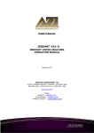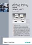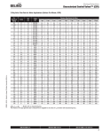
1
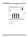
SiPass integrated
AFO5200
Installation Manual
Fire Safety & Security Products
Siemens Building Technologies
Liefermöglichkeiten und technische Änderungen vorbehalten.
Data and design subject to change without notice. / Supply subject to availability.
© 2008 Copyright by
Siemens Building Technologies
Wir behalten uns alle Rechte an diesem Dokument und an dem in ihm dargestellten Gegenstand vor. Der Empfänger erkennt diese Rechte
an und wird dieses Dokument nicht ohne unsere vorgängige schriftliche Ermächtigung ganz oder teilweise Dritten zugänglich machen oder
außerhalb des Zweckes verwenden, zu dem es ihm übergeben worden ist.
We reserve all rights in this document and in the subject thereof. By acceptance of the document the recipient acknowledges these rights
and undertakes not to publish the document nor the subject thereof in full or in part, nor to make them available to any third party without our
prior express written authorization, nor to use it for any purpose other than for which it was delivered to him.
Contents
1
Product description ................................................................................5
2
Safety .......................................................................................................5
3
3.1
Technical specifications ........................................................................6
Dimensions ...............................................................................................7
4
Ordering data...........................................................................................8
5
Scope of delivery ....................................................................................8
6
Installation ...............................................................................................9
7
7.1
7.2
7.3
7.4
7.5
7.6
Connections and LEDs.........................................................................10
Connections ............................................................................................10
Port locations ..........................................................................................10
Wiring of monitored input ........................................................................11
FOR inputs ..............................................................................................11
Links and jumpers ...................................................................................13
LEDs .......................................................................................................14
8
Recommended cable specifications ...................................................15
9
Programming and firmware download ...............................................15
10
10.1
Disposal .................................................................................................16
Record of proper waste management.....................................................16
3
Siemens Building Technologies
Fire Safety & Security Products
05.2008
4
Siemens Building Technologies
Fire Safety & Security Products
05.2008
Product description
1
Product description
The AFO5200 is an input/output module that provides an interface between input
and output devices and an Advanced Central Controller (ACC) in a Siemens access control and security environment.
2
Safety
PLEASE NOTE
PLEASE NOTE
DANGER
We decline any liability for material damage or personal injury caused by improper use or non-observance of these safety instructions. In such case any
guarantee expires.
Connection, commissioning and maintenance must only be carried out by suitably qualified personnel.
Correct and safe operation of this device depends on proper transport, storage,
installation and connection, as well as careful operation and maintenance.
Work on electrical systems should only be performed by trained personnel
under the supervision of a certified electrician in accordance with the appropriate regulations.
5
Siemens Building Technologies
Fire Safety & Security Products
05.2008
Technical specifications
3
Technical specifications
Electrical
Power (input)
12 V DC, -15 to +10% or
24 V DC, -15 to +10%
Consumption
max. 2 A @ 12 V DC, max. 1.5 A @ 24 V DC
(Fully loaded: All Relays are driven and the Aux
Power Output supplies its max current of 1.5 A)
Communications FLN
RS-485 two wire, half-duplex
Inputs (internally supplied)
8 x Auxiliary (unsupervised or supervised)
Outputs
8 x Relay 2 A @ 30 V DC
Fire Override (FOR) input
1 x Fire Override input
Normal or Enhanced Modes:
z Normal mode requires an input voltage
of 12 V DC
z Enhanced mode requires the connection of
22 kOhm resistor circuits. Cable must be shielded
and total cable run resistance must not exceed
100 Ohms.
Fire Override (FOR) output
1 x Relay 2 A @ 30 V DC
Local input
1 x passive device connection
Local output
1 x open-collector 100 mA @ 9.7 – 12 V DC
Aux Power output
1.5 A @ 9.7 – 12 V DC
Dimensions
with base plate (W x H x D)
250 x 210 x 40 mm (9.84 x 8.27 x 1.57")
without base plate (W x H x D) 216 x 190 x 28 mm (8.50 x 7.48 x 1.10")
Environmental
Operating Temp
0 – 50 °C (32 – 122 °F)
Storage Temp
0 – 60 °C (32 – 140 °F)
Humidity
10 – 90% RH (non-condensing)
Standards and Guidelines
European Directives
“Directive of Electromagnetic
Compatibility”
Emitted interference:
EN 61000-6-3: 2001
C-Tick
Standard for Australia and New Zealand
(equivalent to EN 55022 of the European Directive).
UL-Directives
UL 294 Access control units. Details can be found
under: http://database.ul.com/cgibin/XYV/template/LISEXT/1FRAME/gfilenbr.html
with UL File Number: BP9490
EN 55022 +A1 +A2 Kl. B: 2003
Interference resistance:
EN 50130-4 +A2: 2003
6
Siemens Building Technologies
Fire Safety & Security Products
05.2008
Technical specifications
3.1
Dimensions
Fig. 1
Dimensions (including base plate)
z Width: 250 mm (9.84")
z Height: 210 mm (8.27")
z Depht: 40 mm (1.57")
7
Siemens Building Technologies
Fire Safety & Security Products
05.2008
Ordering data
4
5
Ordering data
Type
Part no.
Designation
Weight
AFO5200
S24246-A2600-A1
Eight Input Output Module
0.7 kg
Scope of delivery
1 x AFO5200 mounted on base plate
1 x accessory bag (resistors for monitored inputs)
1 x installation manual English
1 x installation manual German
8
Siemens Building Technologies
Fire Safety & Security Products
05.2008
Installation
6
Installation
Required tools & material
z Medium-duty drill and associated drill-bits
z 4 mounting screws or standoffs (approx. 4 mm)
z Flat-blade terminal screwdriver
z Wire cutters
z Cable strippers
Expected installation time
30 minutes
Mounting instructions
1.
Remove the AFO5200 from its carton and discard the packaging material.
2.
Place the AFO5200 (base plate) against the surface to which it is to be affixed
and mark the location of the mounting holes.
We recommend to mount the AFO5200 within a cabinet. Align the AFO5200
base plate with the holes located on the cabinet backplane and proceed to
step 3.
It is recommended that you affix the AFO5200 at all four of the mounting locations provided.
Warning
Do not apply power to the AFO5200 or associated components at this stage.
3.
Select the appropriate drill bit according to the mounting surface / hole size
and drill the holes in the locations marked (if required).
4.
Fasten the AFO5200 (base plate) to the surface using the correct type of
screws or standoffs for the surface.
5.
Connect the AFO5200. For more information, see Section 7.1: Connections.
6.
Apply power to the AFO5200 and test its operation.
This step may require installation and programming of the access control host
software and download of the firmware instruction set.
Alternatively, the firmware and configuration may be carried out using the FLN
Field Service Tool.
9
Siemens Building Technologies
Fire Safety & Security Products
05.2008
Connections and LEDs
7
Connections and LEDs
7.1
Connections
It is recommended that you wear a grounding strap while carrying out this procedure.
1.
Connect all input devices to the ports INPUT1 to 8.
Listed end-of-line resistors must be connected to the wiring for each input device if they are to be
supervised. For more information, see Section 7.3: Wiring of monitored input.
Please note (this applies to all inputs): The total cable run resistance must not exceed 100 Ohms.
7.2
2.
Connect all output devices to the ports RELAY OUTPUT1 to 8. Access doors
can only be connected to relay outputs that are controlled by readers.
3.
Connect the wiring from the Fire and Emergency Override system to the
FOR IN port. Ensure the correct FOR link settings are applied.
4.
Connect the next device in the Fire Override sequence to the FOR OUT port.
5.
Connect the FLN wires (from the ACC) to the FLN RS485 port.
6.
Connect the active (+ve) and neutral (-ve) wires from the power supply unit
(PSU) to the DC POWER IN port. Ensure the polarity of the connection is made correctly.
7.
Check all jumpers. For more information, see Section 7.5: Links and jumpers.
8.
Check all connections thoroughly, including the polarity of each connection.
Once you have verified all connections power can be applied to the AFO5200.
Port locations
Port name
Description
DC POWER IN
DC power input (12 V DC or 24 V DC).
FLN RS485
RS-485 bus for AC5100, FLN bus
RELAY OUTPUTS 1-8
Auxiliary relay outputs.
INPUTS 1-8
Inputs
∗
FOR IN
∗
∗
FOR input (e.g. fire alarm button)
FOR OUT
FOR output
LOCAL IN
Tamper input for local tamper detection
LOCAL OUT
Alarm output (e. g. siren, strobe light)
+12V OUT
Auxiliary 12 V DC power output
FOR: Fire Override
10
Siemens Building Technologies
Fire Safety & Security Products
05.2008
Connections and LEDs
7.3
Wiring of monitored input
1
Connect the shielding to the housing earth.
2
Insulate the shielding at the input (e.g. door contact), do not connect it.
3
DC: Door contacts
4
R: Terminating resistors 22 kOhm each
Fig. 2
7.4
Wiring of monitored input
FOR inputs
AFO5200
∗
FOR input
(normal mode)
External device
Fire alarm system
(+ UB)
Port
Remark
Fire alarm system output:
Fire alarm system OK
Î +12 V
In case of fire alarm or malfunction
Î0 V
∗
FOR input
(normal mode)
Fire alarm system
(relay contact)
Fire alarm system output:
Fire alarm system OK
Î contact between NO and COM
closed
In case of fire alarm or malfunction
Î contact between NO and COM
open
∗
FOR input
Fire alarm system
Fire alarm system output:
(enhanced
mode)
(relay contact)
Fire alarm system OK
Î contact between NO and COM
closed
In case of fire alarm or malfunction
Î contact between NO and COM
open
∗
FOR: Fire Override
11
Siemens Building Technologies
Fire Safety & Security Products
05.2008
Connections and LEDs
The following diagram provides an example for wiring a door lock in a fail-safe
mode for fire override operation:
12
Siemens Building Technologies
Fire Safety & Security Products
05.2008
Connections and LEDs
7.5
Links and jumpers
Jumper
Description
Value
LK1 + LK2
FOR MODE
LK1
LK2
Configuration of the Fire Override mode:
– Enhanced FOR mode (monitored)
– Normal FOR mode (floating).
Jumpers placed over both links:
Î Input set to Normal FOR mode.
Jumpers not placed:
Î Input set to Enhanced FOR mode.
LK3, LK4 + LK8
These links are general purpose links that have been included for future enhancement.
LK5
GP1 RESET MODE
Reset the firmware:
– Close LK5
– Close link 9, wait for the activity LED to switch off, then remove LK9.
– Remove LK5 before loading the new firmware
LK6 + LK7
FOR AKTIVATION
FOR ENABLE
FOR ENABLE
– FOR enabled
Î Activation of the FOR input will cause the appropriate
output relays to pick up or drop out depending on where the
links LK10 – LK17 are placed.
– FOR disabled
LK6 LK7
LK6 LK7
Î The input will have no effect on the relays.
FOR disabled
LK9
FOR enabled
RESET (Restart)
Reset the AFO5200 retaining the unit’s firmware:
– Interrupt the power supply to the unit for 1 sec or
– Close link 9, wait for the activity LED to switch off, then remove LK9.
LINKS 10 – 17
FOR OUTPUT CONTROL
FOR EN
These links control the Fire Over-ride activation for each
individual relay output 1-8.
Depending on where you place the link, the relay output
behaviour will be modified by the FOR input, or FOR will be
disabled for that relay.
FOR DIS
LK10
LK11
Output OUT8 (LK10): FOR disabled
Output OUT7 (LK11): FOR enabled.
LK18
EOL TERMINATION (FLN System Bus)
This link allows the RS485 bus communication channel to be terminated in lengthy comms lines – more than
100 m at 115 kb/s.
Note: Only units that are located at the ends of bus lines should have Link 26 set to on.
LK 19 + LK 20
BIAS
Jumper placed across LK19 and LK20:
These links enable the RS-485 bus biasing resistors. The
Î RS485-FLN biasing resistors enabled.
resistors create a voltage divider to force the voltage to be
LK19
LK20
less than the threshold of the receiver. This prevents invalid
data bits that are picked up from the noise on the cable from
being transmitted.
13
Siemens Building Technologies
Fire Safety & Security Products
05.2008
Connections and LEDs
7.6
LEDs
LED
Description
PWR
LED active: power is applied to the PCB
ACT
ACTIVITY LED
1. LED blinking quickly: Firmware needs to be downloaded
2. LED blinking slowly (approx. once per sec): Firmware has been downloaded
COM
The LED flashes when the AFO5200 is sending data to the AC5100.
OUT1-8
LED active: Relay active (green LED active – relay active).
IN1-8,
Status of inputs
FOR IN
LED red: Alarm (Fire Override at FOR input)
LED green: Normal
LED orange: Tampering
LED off (only FOR IN): FOR disabled
14
Siemens Building Technologies
Fire Safety & Security Products
05.2008
Recommended cable specifications
8
Recommended cable specifications
The table provides a guideline for selecting an appropriate cable type only.
Other cable types are also compatible with the system and can be used to achieve the same results.
Recommended Cable Specifications
Communication Type
Cores
Pairs
RS-485
4
2
6
3
8
4
4
2
6
3
8
4
4
2
6
3
8
4
8
RS-232
RS-422
RJ-45
RJ-12
Power (12/24
V DC)
9
AWG
Cores
J-Y(St)Y
Diameter
(mm)
Wire Type
Insulation
Shield
Jacket
28
7 x 36
0.6
Tinned
Copper
Foam
Polyethylene
Aluminium foil - Polyester
tape / braided shield
PVC
24
7 x 32
0.6
Tinned
Copper
Foam
Polyethylene
Aluminium foil - Polyester
tape / no braid
PVC
24
7 x 32
0.6
Tinned
Copper
Foam
Polyethylene
Aluminium foil - Polyester
tape / no braid
PVC
4
24
Solid
0.6
Bare Copper
4
24
7 x 32
0.6
Tinned
Copper
Polyethylene
Unshielded
PVC
8
8
4
24
Solid
0.6
Bare Copper
8
4
24
7 x 32
0.6
Tinned
Copper
Polyethylene
Aluminium foil - Polyester
tape / no braid
PVC
2
1
18
19 x 30
1.0
Tinned
Copper
Foam
Polyethylene
Unshielded
PVC
Programming and firmware download
The AFO5200 is programmed using SiPass software, via the AC5100, or using the
„FLN Configurator“ application. Please refer to the appropriate User’s Manual for
more information.
15
Siemens Building Technologies
Fire Safety & Security Products
05.2008
Disposal
10
Disposal
All electrical and electronic products should be disposed of separately from the
municipal waste stream via designated collection facilities appointed by the government or the local authorities.
This crossed-out wheeled bin symbol on the product means the product is covered by the European Directive 2002/96/EC.
The correct disposal and separate collection of your old appliance will help prevent potential negative consequences for the environment and human health.
It is a precondition for reuse and recycling of used electrical and electronic equipment.
For more detailed information about disposal of your old appliance, please contact
your city office, waste disposal service or the shop where you purchased the product.
10.1
Record of proper waste management
A record of proper waste management is not required.
16
Siemens Building Technologies
Fire Safety & Security Products
05.2008
17
Siemens Building Technologies
Fire Safety & Security Products
05.2008
18
Siemens Building Technologies
Fire Safety & Security Products
05.2008
Issued by
Siemens Building Technologies
Fire & Security Products GmbH & Co. oHG
D-76181 Karlsruhe
www.sbt.siemens.com
Document no.
A24205-A335-B263
Edition
05.2008
© 2008 Copyright by
Siemens Building Technologies
Data and design subject to change without notice.
Supply subject to availability.
Printed in the Federal Republic of Germany
on environment-friendly chlorine-free paper.