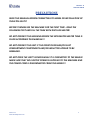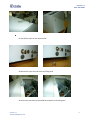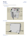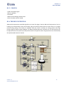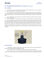
1
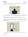
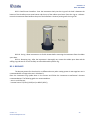
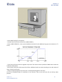
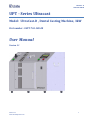
UltraCast - D 0UPT-769-100-00 UPT - Series Ultracast Model: UltraCast-D , Dental Casting Machine, 3kW Part number: 0UPT-769-100-00 User Manual Version 1.1 Version 1.1 www.ultraflexpower.com 1 UltraCast - D 0UPT-769-100-00 PRECAUTIONS READ THIS MANUAL BEFORE CONNECTING TO MAINS OR INSTALLATION OF THEULTRA CAST!!! BEFORE TURNING ON THE MACHINE FOR THE FIRST TIME - READ THE FOLLOWNG TEXT AND FILL THE TANK WITH DISTILLED WATER! DO NOT OPERATE THE MACHINE BEFORE THE INTEGRATED WATER TANK IS FILLED ACCORDING THIS MANUAL!!! DO NOT OPERATE THE UNIT IF THE FRONT DOOR AND/OR CAST COMPARTMENT COMPONENTS AND/OR INDUCTOR APPEAR TO BE DAMAGED. DO NOT OPEN THE UNIT’S COVERS WHILE IT IS CONNECTED TO THE MAINS! MAKE SURE THAT NO ELECTRIC POWER IS SUPPLIED TO THE MACHINE AND THE POWER CORD IS DISCONNECTED FROM THE MAINS!!! Version 1.1 www.ultraflexpower.com 2 UltraCast - D 0UPT-769-100-00 TABLE OF CONTENTS SECTION A: GETTING STARTED GUIDE ................................................................................................................................. 4 A1: SAFETY INSTRUCTIONS .......................................................................................................................................... 4 A1.1 IMPORTANT NOTES ................................................................................................................................................ 4 A1.2 SAFETY PRECAUTIONS ............................................................................................................................................ 5 A1.2.1 ELECTRICAL SHOCK HAZARDS ...................................................................................................................... 5 A1.2.2 GROUNDING ................................................................................................................................................ 6 A1.2.3 SAFETY AND PRECAUTION SYMBOLS USED IN THIS MANUAL ..................................................................... 6 A2: INSTALLATION AND STARTUP ................................................................................................................................ 7 A2.1 INSTALLATION PROCEDURE .................................................................................................................................... 7 A2.2 UNPACKING AND INSPECTION ................................................................................................................................ 7 A2.3 SELECTING THE DEVICE SITE ................................................................................................................................... 8 A2.4 COOLING REQUIREMENTS ...................................................................................................................................... 8 A2.4.1 COOLING WATER FILLING: ................................................................................................................................... 8 A2.5 GAS INPUT CONNECTION ............................................................................................................................................... 11 A2.6 AC INPUT CONNECTION ........................................................................................................................................ 12 A2.7 START-UP ............................................................................................................................................................. 12 A3: MAINTENANCE ..................................................................................................................................................... 13 A3.1 SCHEDULING ......................................................................................................................................................... 13 A3.2 PERSONNEL ........................................................................................................................................................... 13 A3.3 INSPECTION AND MAINTENANCE PROCEDURE .................................................................................................... 13 A4: SERVICE ................................................................................................................................................................. 14 A4.1 GENERAL ............................................................................................................................................................... 14 A4.2 SERVICE CONTACT INFORMATION ....................................................................................................................... 14 SECTION B: PRODUCT SPECIFICATIONS AND FEATURES .................................................................................................... 15 B1: POWER SUPPLY SPECIFICATIONS .......................................................................................................................... 15 B1.1 OVERVIEW ............................................................................................................................................................ 15 B1.2. TECHNICAL DATA ................................................................................................................................................... 15 B1.3. OVERALL DIMENSIONS ........................................................................................................................................... 15 B1.4. CONTROLS .............................................................................................................................................................. 16 B1.4.1. Front side. ...................................................................................................................................................... 16 B1.4.2. Back side........................................................................................................................................................ 16 B1.5. PROCESS:................................................................................................................................................................. 17 B1.6. THEORY OF OPERATION:......................................................................................................................................... 17 B2: PREPARATION FOR USE FOR STANDARD DENTAL ALLOYS .......................................................................... 18 B2.1. SPRUING: ................................................................................................................................................................ 18 B2.2. INVESTING: ............................................................................................................................................................. 18 B2.3. BURNOUT:............................................................................................................................................................... 20 B3: TITANIUM CASTING ................................................................................................................................................ 22 B3.1. MATERIALS .............................................................................................................................................................. 22 B3.2. WAX MODELS ......................................................................................................................................................... 22 B3.3. FLASK ...................................................................................................................................................................... 22 B3.4. MAKING THE FLASK ................................................................................................................................................ 22 B3.5. CASTING .................................................................................................................................................................. 23 B4: CONTROLS AND OPERATION .................................................................................................................................. 24 B4.1. OPERATION CYCLE: ................................................................................................................................................. 24 B4.2. CONTROLS AND DISPLAY READOUT ....................................................................................................................... 25 B4.2.1 MAIN OPERATION: ........................................................................................................................................ 25 B4.2.2 PROCESS CONTROL: ....................................................................................................................................... 28 SECTION C. ACCESSORIES ...................................................................................................................................................... 29 Version 1.1 www.ultraflexpower.com 3 UltraCast - D 0UPT-769-100-00 SECTION A: A1: GETTING STARTED GUIDE SAFETY INSTRUCTIONS A1.1 IMPORTANT NOTES 1. This manual is valid only for the Model and the associated Revision number(s) specified in the cover sheet of this manual. A Change Page may be included at the end of the manual. All applicable changes are documented with reference to the equipment Revision and Serial number. Before using this Instruction Manual, check your equipment nameplate to identify your Model and Revision number. If in doubt, contact your nearest Ultraflex Power Technologies (UPT Corp.) Representative; 2. This document contains information proprietary to UPT Corporation. All rights are reserved. No part of this document may be reproduced, transmitted, processed or recorded by any means or form, electronic, mechanical, photographic or otherwise, nor be released to any third party without the express written consent of UPT Corporation; 3. Data subject to change without notice; 4. All Information contained in this manual is the latest information available at the time of printing. The right is reserved to make changes at anytime without notice. UPT Corp. makes no warranty of any kind with regard to this material and assumes no responsibility for any errors that may occur in this manual; 5. Safety First! YOU AND NOT THIS MANUAL ARE REPONSIBLE FOR ALL SAFETY PRECAUTIONS This manual is for reference purposes only. Personnel should be trained on proper operation of this equipment before using. Only authorized personnel may perform any troubleshooting or repair on any UPT manufactured equipment. Failure to comply will void warranty. Please, contact the UPT Service Department before servicing any UPT equipment. Lethal voltages may be present in equipment surrounding and/or connected to this equipment. Read the following warnings carefully and study this entire manual before operating the system. Failure to observe warnings may result in equipment damage, serious personal injury, or death. If the equipment is used in a manner not specified by this manual, the protection provided by the equipment may be compromised and damage to the unit may occur. Only qualified persons who have been trained in the operation of this equipment and are familiar with the technology should be permitted to operate the system; Version 1.1 www.ultraflexpower.com 4 UltraCast - D 0UPT-769-100-00 1. Installation, assembly, inspection maintenance and servicing are to be performed by authorized personnel only; 2. Always have the Power Supply completely powered OFF and locked out before performing any service, inspection or maintenance; 3. Even with the Power Supply OFF, live voltages still exist within the cabinet. Always power OFF and lock out the external power source to ensure no one can accidentally energize it; 4. Ensure that all external wiring conforms to applicable codes; 5. Obey all warnings and use good common sense; A1.2 SAFETY PRECAUTIONS A1.2.1 ELECTRICAL SHOCK HAZARDS This manual is written for personnel familiar with the technology pertaining to the operation of induction heating equipment. Such personnel should be thoroughly familiar with the hazards associated with this equipment and electrical equipment in general, and they should have received proper safety procedure training. Hazardous voltages are present within this product during normal operation. The product should never be operated with the cover removed unless equivalent protection of the operator from accidental contact with hazardous internal voltages is provided. Operators must be trained in its use and exercise caution as well as common sense during use to prevent accidental shock. There are no operator serviceable parts or adjustments within the product enclosure. Refer all servicing to trained service technician. Source power must be removed from the product prior to performing any servicing. This product is designed for use with nominal a-c mains voltages indicated on the rating nameplate. Version 1.1 www.ultraflexpower.com 5 UltraCast - D 0UPT-769-100-00 A1.2.2 GROUNDING This product is a Class 1 device which utilizes protective grounding to earth to ensure operator‘s safety. PROTECTIVE EARTHING CONDUCTOR TERMINAL -This symbol indicates the point on the product to which the protective grounding conductor must be attached. EARTH (GROUND) TERMINAL -This symbol is used to indicate a point which is connected to the PROTECTIVE EARTHING TERMINAL. The component installer/assembler must ensure that this point is connected to the PROTECTIVE EARTHING TERMINAL. CHASSIS TERMINAL -This symbol indicates frame (chassis) connection, which is supplied as a point of convenience for performance purposes. This is not to be confused with the protective grounding point, and may not be used in place of it. A1.2.3 SAFETY AND PRECAUTION SYMBOLS USED IN THIS MANUAL A WARNING symbol alerts you to a hazard that may result in equipment damage, personal injury, or death. Carefully read the instructions provided WARNING and follow all safety precautions. A CAUTION symbol alerts you that the system may not operate as expected if instructions are not followed. Version 1.1 www.ultraflexpower.com 6 UltraCast - D 0UPT-769-100-00 A2: INSTALLATION AND STARTUP A2.1 INSTALLATION PROCEDURE The installation procedure consists of the following steps: 1. 2. 3. 4. 5. Unpacking the equipment; Selecting the site where the equipment will be used; Connecting the Heat Station (if remote Heat Station is provided); Connecting accessories or interfacing the system with other controls (if necessary); Completing the Power and Ground/Earth connections; Power and ground/earth connections must be made last. Failure to do so will create a hazardous condition that may result in equipment damage, personal injury, or death. NOTE: UPT Corporation has a staff of field engineers who are available to supervise the installation of the equipment. If installation service is required, contact our Technical Service Department for additional information. Provisions for facility electrical power service are customer furnished. Requesting field engineering assistance before customer furnished provisions are installed at the equipment site could delay equipment installation and cause unnecessary expense. A2.2 UNPACKING AND INSPECTION This equipment has been thoroughly inspected and tested prior to packing and is ready for operation. After careful unpacking, visually inspect for shipping damage BEFORE attempting to operate. If any indication of damage is found, file an immediate claim with the responsible transport service and advise your sales representative. Inspect equipment before installing. Damaged equipment may result in improper operation and create a hazardous condition resulting in personal injury or death. The carrier is responsible for all damage caused in shipment including concealed damage. Version 1.1 www.ultraflexpower.com 7 UltraCast - D 0UPT-769-100-00 A2.3 SELECTING THE DEVICE SITE Consider the following when choosing a location for the device: Make sure the system is installed in a debris free zone; The device has to be connected to a power source and cooling water; The device have to be connected to cooling system with sufficient water flow; Make sure the device is easily accessible by the operator; Device has to be seated on a mechanically secure surface. A2.4 COOLING REQUIREMENTS The power transistors and rectifiers into the device are maintained within their safe operating temperature range by means of water cooling. The fan inlets must be kept clean from obstructions in order to insure proper air circulation. If installed in confined spaces, care must be taken that the ambient temperature (the temperature of the space immediately surrounding the device, does not rise above the limit specified as 40°C. Periodic cleaning of the device exterior is recommended. The following system components are directly dependent on water cooling: semiconductor’s heat sinks, coils, tank capacitors, output transformers. To maintain the temperature on these components within safe limits, the following requirements apply to the inlet cooling water: Maximum allowable temperature – 95˚F (35°C). Minimum allowable temperature - 58˚F (14°C) (to avoid condensation). Minimum water flow is required – Refer to product specifications in Section B. Water (coolant) must be mechanically debris free. Water (coolant) must be chemically pure (distilled water is recommended). A2.4.1 COOLING WATER FILLING: UltraCast D is delivered with empty cooling water tank. It must be filled before operating. Those are the steps that should be followed when filling the water tank of the Unit: 1. Remove the top cover using the manufacturer provided tool to unscrew the fasteners !!!Caution: While doing the next steps, sensitive machine circuitry will be exposed. Please, keep out of the system components and items, not participating in the water filling procedure in order to avoid damage to the unit or prevent risk of electric shock during following operation. Version 1.1 www.ultraflexpower.com 8 UltraCast - D 0UPT-769-100-00 2. Take off the cap from the output orifice 3. Remove the cap at the end of the tank filling hose 4. Connect the manufacturer provided funnel with the tank filling hose. Version 1.1 www.ultraflexpower.com 9 UltraCast - D 0UPT-769-100-00 5. Carefully start pouring distilled water into the funnel until it starts to run out. !!!Caution: If you happen to spill water over the electric/electronic circuitry, connectors or circuit breakers you should not under any circumstances connect the unit to the mains until 24 hours have passed from the spillage. If this situation occurs leave the unit with the cover removed for 24 hours in a well ventilated indoor place then make sure the locations affected are dry, then continue with the rest of the instruction’s steps. Version 1.1 www.ultraflexpower.com 10 UltraCast - D 0UPT-769-100-00 6. Put the output orifice’s and filling hose’s caps back on 7. Make sure that there are no tools or other items left inside the unit. 8. Screw the top cover in its place. !!!The water tank should be topped up monthly. Source power must be removed from the product prior to performing any servicing. DO NOT TURN THE POWER ON IF THE WATER TANK IS EMPTY! THIS WILL LEAD TO THE PERMANENT DAMAGE OF THE WATER PUMP. A2.5 GAS INPUT CONNECTION Connect the GAS connection to an Argon tank. The Argon pressure should be regulated to 80-90 PSI (5,5 – 6,2 bar). DO NOT USE OTHER GASES, SUCH AS PRESURIZED AIR OR NITROGENIUM IF YOU MELT TITANIUM! TITANIUM MUST BE MELT AND CAST ONLY IN NEUTRAL (INERT) GAS ENVIRONMENT TO AVOID SERIOUS DAMAGES OF THE UNIT AND PERSONAL INJURY! Version 1.1 www.ultraflexpower.com 11 UltraCast - D 0UPT-769-100-00 A2.6 AC INPUT CONNECTION The Power supply connects to the power network through a 6 ft (1.80m), power cord (supplied). Additional fuse or circuit breaker and residual current circuit breaker on that power branch is a good choice since it will provide extra protection in addition to the unit’s internal protection. A mechanical switch is also recommended within the operator‘s range and vision and possibly closer to the Power Supply. Only trained personnel should open the unit cover and operate the breakers. Table A1: Wiring Color Code Color 3-Phase Connection Brown Black Gray Blue Phase A Phase B Phase C Neutral Green/Yellow Ground/Earth NOTE: Local codes may have stringent requirements. It is the customer‘s responsibility to be familiar with and to comply with all applicable codes concerning conductor ratings and wiring procedures. An electrician familiar with the local regulations should determine proper wiring connections. A2.7 START-UP 1. Turn the Circuit breakers ON (move up). They are placed on the back side of the unit. 2. Turn the ON-OFF switch to power the system. 3. Check for any Fault or Alarm messages. If the status screen shows “Load Crucible Press Melt” message, then the system is ready for operation. Version 1.1 www.ultraflexpower.com 12 UltraCast - D 0UPT-769-100-00 A3: MAINTENANCE A3.1 SCHEDULING UltraCast D is designed for continuous service and minimum maintenance requirements. The frequency of any maintenance program is a function of environment, degree of equipment use, and product experience. A3.2 PERSONNEL Qualified personnel must perform inspection and maintenance procedures only. Personnel must read and be thoroughly familiar with all safety precautions discussed in this manual. A3.3 INSPECTION AND MAINTENANCE PROCEDURE Note: Always follow approved lock - out / tag - out procedures before performing any service, inspection or maintenance. The following describes inspection procedures to be performed on a daily, weekly, and monthly basis. Daily/Weekly Inspection: It is good practice to do a quick visual inspection of the unit, wiring and connections on a daily and/or weekly basis. Report any apparent changes in performance to responsible personnel so that potential problems can be investigated. Monthly Inspection: Perform the following on a monthly basis: 1. Ensure all wiring connections are secure. Visually inspect for any wear on cabling; 2. Verify that none of the enclosure’s hardware has become loose; 3. Remove any build-up debris that may occur around the fan inlet using a cloth or a vacuum cleaner. Use of compressed air is not recommended; 4. Check the water (coolant) for mechanical debris or impurities. The water should be kept clean; 5. Wipe the Control Panel with a damp cloth to remove any dirt, prints or smudges; 6. Wipe the enclosure down with a damp cloth or paint friendly cleaner, if desired; 7. Unbolt water filter clean it and bolt carefully again. Version 1.1 www.ultraflexpower.com 13 UltraCast - D 0UPT-769-100-00 A4: SERVICE A4.1 GENERAL If for some reason the unit fails in the field it is advisable that the unit be serviced by the manufacturer or its authorized service representative. Should that happen, please contact us immediately (see contact information in Section A4.2). Please have the following information about your unit available upon calling: 1. Unit Model and Revision (located on the label on the back of the unit); 2. Unit’s Serial Number (located on the label on the back of the unit); 3. Line Voltage and frequency; 4. Detailed description of the problem encountered including – load, ambient temperature at the time of the failure; 5. Detailed description of the actions taken; 6. Approximate time in service. If our technical staff is unable to help you over the phone, then a repair authorization number (RA#) will be issued for you. With this number enclosed in you return package you can ship the unit back for repair or request a service engineer to repair the unit on site. A4.2 SERVICE CONTACT INFORMATION For technical service questions, please call: Europe and Asia: + 359 2 480 1900 USA and Canada: + 1 631 467 6814 You may also fax your questions or request: Europe and Asia: + 359 2 480 1910 USA and Canada: + 1 631980 4065 Or e-mail us at: [email protected] You can also send you request through our web site. Note: Please, include your contact information so that you can be easily reached if necessary. Version 1.1 www.ultraflexpower.com 14 UltraCast - D 0UPT-769-100-00 SECTION B: B1: PRODUCT SPECIFICATIONS AND FEATURES POWER SUPPLY SPECIFICATIONS B1.1 OVERVIEW UltraCast D is an advanced yet simple dental / jewelry casting machine. The unique design eliminates the need for crucibles by incorporating the crucible’s function into the invested ring. The heating is done quickly and safely via high power induction heating. The UltraCast D can heat all metals. UltraCast D has an integrated cooling system that allows as many as 15 sequential casts to be done at 100% (full power). After such number of jobs performed a working cycle break is needed for the unit, so the cooling water in the tank to reach room temperature. B1.2. TECHNICAL DATA Power supply ..............................................................................98 – 264 VAC (50Hz) Maximum supply current.....................................................................................22 A Maximum power ............................................................................................4,8 kVA Gas supply......................................................................................................... Argon Cooling system ....................................................................................water, built-in Minimum alloy quantity into the crucible................................................................ Maximum alloy quantity into the crucible................................................................ Melting timeout ...............................................................................................2 min Dimensions L/B/H..............................................................................22” x 19” x 19” Weight without cooling water (delivery condition)........................................< 56kg Weight, filled with cooling water.........................................................approx. 70kg B1.3. OVERALL DIMENSIONS Version 1.1 www.ultraflexpower.com 15 UltraCast - D 0UPT-769-100-00 B1.4. CONTROLS The following diagrams shows the main controls of theUltraCast : B1.4.1. Front side. B1.4.2. Back side. Version 1.1 www.ultraflexpower.com 16 UltraCast - D 0UPT-769-100-00 B1.5. PROCESS: • Load crucible with ingots • Place on platform • Press Melt • Observe metal though protective lens • Press Cast when metal is melted B1.6. THEORY OF OPERATION: Advanced microprocessor controlled algorithms to control the Argon, Vacuum, Melt and Cast pressures. Prior to heating, the microprocessor cycles low pressure argon and vacuum several times to ensure there is no oxygen present during casting. This ensures no oxidation. After the metal is melted, the casting process uses high pressure argon to further reduce oxidation. The Motor and Melt pressures are factory set. The Cast pressure can be adjusted via the front panel to provide perfect casts for all types of metals. All gas pressures are monitored by the sophisticated electronic controls. Version 1.1 www.ultraflexpower.com 17 UltraCast - D 0UPT-769-100-00 B2: PREPARATION FOR USE FOR STANDARD DENTAL ALLOYS B2.1. SPRUING: Spruing for the UltraCast is no different than spruing for all other casting systems – with one exception: All sprues must be attached to a “Pentaform” wax sprue button. B2.1.1. Pentaform - Press the Pentaform down into a rubber base as far as it will go. The Pentaform will not go all the way down. There must be a minimum of 1/8” (3,2 mm) gap between the bottom of the Pentaform wax sprue button and the top of the rubber sprue base. DO NOT add wax between the Pentaform and the rubber base. B.2.1.2. Rubber Base - Place a Pentaform on the rubber sprue base first, and then attach your waxup with the sprue(s) to the Pentaform. B2.1.3. Spruing Tips: Use hollow sprues whenever possible. This will decrease the possibility of damaging the investment during burnout. Keep all sprues as short as possible. Your secondary sprues should be 10-12 mm. Place a reservoir opposite all pontics and full cast crowns. The reservoir should be equal in size to the pontic. Each pontic must have its own sprue with a reservoir. Two ponitcs should have two sprues with reservoirs. Etc. Keep out of the “Thermal Zone”. Always angle waxup toward the outside of the ring. Never have more than ¼” (6,35mm) of investment above your waxup or your waxup will be in the Thermal Zone. Never add wax to your rubber base. Simply press the Pentaform into place and attach your waxup and sprues to the top of the Pentaform. B2.2. INVESTING: The objective is to obtain a strong investment whose top and bottom surfaces are reasonably parallel in order to obtain a good seal against the gasket when casting. B2.2.1. Preparation - Do not use debubblizer. Carefully paint investment into wax copings. B2.2.2. Investment Types - Use only high temperature phosphate-bonded investments. Recommended material is as follows: Hi-Temp (or equivalent) for palladium and non-presious metal • Ceramigold (or equivalent) Version 1.1 www.ultraflexpower.com 18 UltraCast - D 0UPT-769-100-00 for Type III and Ceramanic Alloys (or equivalent). Note – Do not use Cristobolite types of investment in UltraCastD. This material is too soft and will not hold up under pressure. B2.2.3. Plastic Ring - Be sure plastic rings are pressed down fully into grove in the rubber sprue base. Keep the inside of sprue formers clean to permit proper sealing of the ring and a smooth surface on the investment. B2.2.4. Ring Height - Investment should be > ¼” (6,35mm) above the wax pattern. B2.2.5. Stiffening Ring - Place the Stiffening Ring prior to pouring or immediately after pouring the investment. B2.2.6. Clean Mixing Bowl - Be sure the mixing bowl is clean prior to mixing the investment. Any trace of plaster or die stone in your investment will destroy its strength. It is best to use separate mixing bowls for each type of investment used. B2.2.7. Evacuate - Evacuate all air using a bell jar vacuum (or equivalent) prior to pouring. B2.2.8. Pour Level - Pour your investment into the ring on a FLAT and LEVEL surface. This will insure both ends are reasonably parallel. Version 1.1 www.ultraflexpower.com 19 UltraCast - D 0UPT-769-100-00 B2.2.9. Careful near Pentaform - Pour the investment slowly into the ring until the level is between the bottom of the Pentaform wax sprue button and the top of the rubber sprue base. Place the ring on a vibrator. Insure the investment flows between the pins of the Pentaform. Continue pouring until the ring is full. B2.2.10. Curing - Allow investment to sit for 60 minutes before removing the investment from the rubber sprue base. B2.2.11. Removing ring - After the investment is thoroughly set, remove the rubber sprue base and the stiffing ring and save for reuse. Carefully cut off and discard the plastic ring. B2.3. BURNOUT: The burnout process for UltraCast D is no different than any other casting system. A two stage burn out is recommended for all rings to be cast in UltraCast D. Place the investment ring upside down in the furnace and follow the investment manufacturer’s burnout recommendations. The following guide is a recommendation: - start in a cold furnace; - increase heat at 7ºF/min (0,33ºC/min) to 600ºF (315ºC); Version 1.1 www.ultraflexpower.com 20 UltraCast - D 0UPT-769-100-00 - hold at 600oF (315ºC) for 30 minutes; - increase heat at 20ºF /min (11ºC/min) to 1600VF (870ºC); - hold at 1600ºF (870ºC) for 1 hour, plus 10 additional minutes for each additional ring (up to a maximum or 1-½ hours). - if your burnout furnace does not regulate ramp times. Then heat as slow as possible to 600oF and increase the hold time to 60 minutes. - the minimum final soak is 60 minutes for all alloys. Additional soak time varies according to size and number of rings in the burnout furnace. - if rings are kept overnight, be sure they are in a sealed plastic bag with a wet tissue. do not use Cristobolite types of investment in the Ultracast. They are too soft and will not hold up under pressure. Version 1.1 www.ultraflexpower.com 21 UltraCast - D 0UPT-769-100-00 B3: TITANIUM CASTING B3.1. MATERIALS The UltraCast can work with any type of investment material. However we have made successful titanium castings with the following materials: Investment material: Rematitan plus Speed. Mixing liquid: Rematitan Plus Speed liquid. Zirconium paint: Z-O paint, Gesswein. B3.2. WAX MODELS Preparation of the wax models is extremely important for the quality of your castings. When preparing the wax model make sure that you use enough compensators to allow the gas to be evacuated from the model during casting. Also the volume of the spruing system must be enough to allow even and complete filling of the model. B3.3.FLASK To prepare the flask as in defined in section B2! B3.4. MAKING THE FLASK Carefully follow the instructions provided by the manufacturer of the investment material and the mixing liquid! 1. Mix the investment material following as per the manufacturer instructions (Fig.B1). Do not use the same measuring flask and stirrer for other investment materials! Use vacuum mixer to avoid bubbles in the investment. Version 1.1 www.ultraflexpower.com 22 UltraCast - D 0UPT-769-100-00 Fig. B1 Fig. B2 2. Fill the mold with the investment material (Fig.B2). 3. Allow 10-15 minutes for the flask to cure. Note – the mold will get hot during the curing cycle. 4. When the investment is fully cured remove the top ring and the rubber base and cut away the plastic tube. 5. Paint the inside of the “crucible” with 2-3 thick layers of Zirconium paint (allow time for each layer to dry). This keeps the titanium from reacting with the oxygen in the investment material during melting and improves the quality of your castings (Fig.B3). The flask is now ready to be placed in a burnout oven. When burning the flask follow the manufacturer's instructions carefully (Fig.B4). Fig. B3 Fig.B4 For Rematitan Plus Speed: Heat the oven to 950oC. Put the flask inside and burn for at least 1 hour. Add 5 minutes for each additional flask. When complete, remove flask and leave at room temperature for 45 minutes or until the temperature is around 150 degrees C. B3.5. CASTING 1. Use ONLY ONE Titanium ingot! Additional ingots will create areas that are overheated and other areas that are under heated (Fig.B5). Version 1.1 www.ultraflexpower.com 23 UltraCast - D 0UPT-769-100-00 NEVER ATTEMPT TO HEAT “USED” TITANIUM. Titanium can NOT be re-melted. Fig.B5 Fig.B6 Fig.B7 Fig.B8 2. Use 99.750% (or better) pure Titanium Ingots. The melting point is approximately 1670 °C (Fig.B6). Push the cast button when you see the 98% of the Titanium ingot is melted. 3. When the casting process is complete, immediately place Flask in a large amount of water to stop the Alpha Case production (Fig.B7). 4. Remove the remaining investment around the casting using sandblaster (Fig.B8). Use aluminum oxide, grain size 125-250 µm. Your titanium casting is ready! Please note that titanium is a difficult metal to cast and to achieve good results you need experience. This procedure will give you the basic tips but to make the perfect casting you will need to practice. B4: CONTROLS AND OPERATION B4.1. OPERATION CYCLE: 1. Turn On: Turn on the Circuit Breaker, the Power Switch, Argon and Water. Open the door. 2. Check Casting Pressure: 30 PSI (2 bar) for Non-precious metals 25 PSI (1,7 bar) for precious metals (gold, platinum, aspen, etc.). 3. Load: Remove the hot investment ring from the burnout oven. Load the investment ring with raw metal. Place the investment ring on the Base Ring Positioner. Close the door. Version 1.1 www.ultraflexpower.com 24 UltraCast - D 0UPT-769-100-00 4. Melt: Press the Melt Button. Monitor the metal heating through the viewing window. A protective lens is provided to safely view the molten metal. When the metal liquefies it is ready to cast. 5. Cast: Press the Cast button when the metal liquefies. The UltraCast will automatically cast using argon pressure. When the cast is complete, the platform will lower and the investment can be removed. B4.2. CONTROLS AND DISPLAY READOUT B4.2.1 MAIN OPERATION: 1. The Casting cycle step-by-step: Close the chamber door if it is open! Turn the POWER ON, using the circuit breakers and main POWER ON switch. On the display you read: Initializing After 5sec for initialization. Enterprise Ultra Cast Rev-2.1 During this time, the internal control runs the platform down. Normally the platform is in lower position after the last previous operation cycle, so it just remains there. This action is necessary to guarantee the platform lower position (e.g. after gas pressure failure). It is recommended to turn on UltraCast D by closed chamber door to avoid eventual platform movement. Version 1.1 www.ultraflexpower.com 25 UltraCast - D 0UPT-769-100-00 After the initialization the unit is ready for use and on the display you read flashing both windows: Load Crucible Press Melt MELT = XX.X PSI Recommend 8-10 PSI Open the door. Place the loaded with raw metal investment ring on the Base positioner. Close the door and press the MELT button. On the display you read: Raising Platform After 2 sec for raising: Platform is raised Successfully And X.X to Melt Vacuum = xxx mbar The time period of 5 sec elapses here for vacuum and inert gas environment preparation. After 5 sec: Increasing Pressure Time Left: X.X sec After 2 sec the internal control turns on the heating. MELTING X.X PSI CAST when Ready Monitor the metal heating through the viewing window. A protective lens is provided to safely view the molten metal. When the metal liquefies it is ready to cast. Press the CAST button. CASTING = XX Sec Pressure = X.X PSI UltraCast D turns the heating off and will automatically cast using argon pressure. When the cast is complete, the platform will lower and the investment can be removed. Lowering Platform Caution Hot Crucible Version 1.1 www.ultraflexpower.com 26 UltraCast - D 0UPT-769-100-00 After 2 sec for platform lowering: Cast Complete Caution Hot Crucible Open the door and remove the investment. 2. Safety and door Interlock. All actions, described above (in point 1.), except placement and removing of the investment, are possible only by closed chamber door. Any try to use the equipment by open door leads to termination of the current step (process) and an alarm message: ALARM Chamber Door Open The red alarm light turns on and the button STOP lights in red. NOTE! By termination of the process the platform runs down to the lower position. During its movement the STOP button and the alarm light are turned ON. You can release the alarm condition by pressing the button STOP after the platform is down. Keep your hands away from the moving parts into the chamber until the platform stops in the lower position! 3. Termination by the user. You can terminate the process at any time, if it is necessary, by pressing the button STOP. By termination of the process the platform runs down to the lower position. When the platform is there, on the display you read: Process is Canceled Caution Hot Crucible Now you can open the chamber door and get the appropriate action to solve the problem. When you close the door, the unit is ready for use. 4. Failure conditions and messages. If the platform is not raised for 5 sec after the pressing of the button MELT, the unit terminates the process and a warning message: Platform is NOT Raising Process is Canceled Caution Hot Crucible The reason might be low or missing gas pressure, or missing investment. Version 1.1 www.ultraflexpower.com 27 UltraCast - D 0UPT-769-100-00 Some time the investment might be placed in wrong way – eccentric to the positioner or under some slope. TheUltraCast has a built-in safety lock to avoid equipment and user damages. In such case, by the raising of the platform, the unit detects the wrong situation and terminates the process. An alarm message appears on the screen: ALARM Wrong Crucible Pos. Open the door and solve the problem. Release the alarm by pressing button STOP. B4.2.2 PROCESS CONTROL: The Control Panel display will indicate the Power setting (0-100%) and Cast Time in seconds. Normal castings use 100% power and 60 second cast time. TheUltraCast D monitors the following pressures: - platform - recommended pressure is 40-45PSI (2,75 – 3,1 bar); - cast - recommended pressure is 25-30PSI (1,7 – 2 bar); - melt - recommended pressure is 8-10PSI (0,55 – 0,7 bar). If the above pressures are outside the recommended pressure, UltraCast D will indicate a warning. The display will show the actual and recommended values. Please make pressure adjustments if necessary. The UltraCast D will indicate a warning if the water flow is below 0.4 GPM (< 1,5LPM). The Melt button will not function unless the water flow is above 0.4 GPM (> 1,5LPM). The UltraCast D will indicate a warning to replace the gasket every 5 casts. When the gasket is replaced, press the STOP button to reset the warning. The UltraCast D will stop if the temperature of outgoing water exceeds 60degC. Version 1.1 www.ultraflexpower.com 28 UltraCast - D 0UPT-769-100-00 SECTION C. ACCESSORIES The UltraCast D comes with all accessories to begin casting. The following diagram shows all the accessories. The next page contains a list of the contents that are included: List of Accessories: Sprue Button / Penta-Form Rubber Base (4 sizes): 1.75” Rubber Base 2.50” Rubber Base 3.00” Rubber Base 3.50” Rubber Base Ring Stiffener (4 sizes): 1.75” Ring Stiffener Version 1.1 www.ultraflexpower.com Qty 36 Qty 2 Qty 1 Qty 1 Qty 1 Qty 4 29 UltraCast - D 0UPT-769-100-00 2.50” Ring Stiffener 3.00” Ring Stiffener 3.50” Ring Stiffener Plastic Ring (4 sizes): 1.75 x 3.50” Plastic Ring 2.50 x 2.25” Plastic Ring 3.00 x 2.25” Plastic Ring 3.50 x 3.25” Plastic Ring Ceramic Base for 1.75”, 2.5”, 3”, and 3.5” rings Pin Positioner (for partials) Gasket Qty 2 Qty 2 Qty 1 Qty 25 Qty 10 Qty 10 Qty 5 Qty 1 Qty 1 Qty 48 Please make certain that you have all the accessories. Contact the factory if there are any discrepancies. Version history: № 1 2 3 Ver. 1.0 1.1 Date 11.2009 07.2012 08.2012 Version 1.1 www.ultraflexpower.com Remark Original New Design Information for Titanium Create/Change by: L.Mihova L.Mihova 30