1
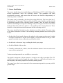
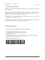
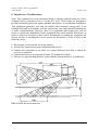
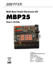
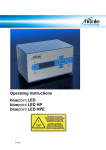
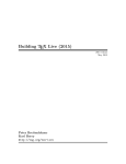
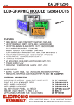
DRS-6/1
Doppler Radar Sensor
B+S Software und Messtechnik GmbH
Lochhamer Schlag 17
D-82166 Graefelfing
Germany
October 1999
User's Manual
Doppler - Radar - Sensor Type DRS-6/1
Users Manual
October 1999
DRS-6 SENSOR for speed measurements
1. DRS-6 Functional Description
Doppler Radar Sensors provide slip and contact-free measurements of speed and
distance.
This sensor measures the vehicle moving speed using the Doppler effect principle.
That is, it measures the frequency shift between transmitted and reflected waves and
this shift is proportional to the vehicle speed.
A sophisticated electronic signal conditioning is required to practically realize this
simple principle. The microwaves are transmitted and then received after reflection by
the same antenna. The Doppler frequency is obtained by mixing the outgoing and
incoming signals. The beam is not focused and therefore the returned beam is reflected
from an area and not from a point. The result is a spectrum shift rather than a single
frequency shift. The characteristic frequency is then amplified and filtered.
This method ensures that the result is as far as possible independent of the type of
reflecting surface and unavoidable vibration.
24 GHz microwaves are used. The Doppler frequency depends on the alignment of the
antenna. To reduce the errors caused by vehicle pitch two transmitter/receiver
antennas are used in the DRS-6. They are mounted at 110 degrees to each other, 35° to
the horizontal, one pointing to the direction of movement, one in the opposite
direction. Signal processors are used to convert the results to a square wave with a
frequency proportional to the velocity as well as a voltage proportional to the velocity.
The sensor housing is water tight and protected against condensation caused by
temperature changes. To prevent ground loops, the base plate is isolated from the
sensor ground.
Type overview
Product code: DRS-6/1 xy
x values:
a for 24.125 GHz microwave frequency
b for 24.200 GHz (Japan version)
y values
a for 10V=200 km/h (125 mph), 69.4 Hz/km/h, 4 mm/pulse
b for 10V=300 km/h (187 mph), 69.4 Hz/km/h, 4 mm/pulse
c for 10V=300 km/h (187 mph), 10 Hz/km/h, 4 mm/pulse
d for 10V=200 km/h (125 mph), 27.77 Hz/km/h, 10mm/pulse
e for 5V=300 km/h (187 mph), 69.4 Hz/km/h, 4 mm/pulse
f for 10V=200 km/h (125 mph), 109,36 Hz/km/h, 120 pulses/ft
(394 pulses/m)
g for 5V=250 km/h (156 mph), 69.4 Hz/km/h, 4mm/pulse
2
Doppler - Radar - Sensor Type DRS-6/1
Users Manual
October 1999
2. DRS-6 Specifications
Measurement range:
200 km/h (125 mph) or 300 km/h (185 mph), see
calibration sheet
Speed accuracy:
<1%
Distance resolution:
appr. 4mm/Pulse, see calibration sheet
Distance accuracy:
<0.2 % over 200m (600ft). v> 7.5km/h (5mph)
Error due to tilt angle:
< 0.4 % at 5 degrees deviation
Frequency output:
appr. 70 Hz per km/h, see calibration sheet
1:1 square wave, TTL, at v > 0.2 km/h (0.12 mph)
DC output:
0 to 10V, 12 bit resolution,sensitivity according to
calibration sheet
Serial interface:
RS 232C, 19.2 kBaud
Temperature error:
< 0,005 % / °C
Operating temperature:
-30 to +70 °C (-22F to 158F)
Power supply:
10 -35V, < 5 W, integrated DC/DC converter
Connector:
10 pin, water tight KPSE connector
A: nc
F: RS 232C TxD
B: ground
G: pulse out
C: analog ground
H: DC in
D: RS 232C ground
I:
analog out
E: nc
K: digital ground
Mounting position at vehicle:
200 - 800mm (8"-32") above the reflecting surface
(ground); 800-1200mm for railway applications; base
plate at right angle to direction of movement; top side
of base plate parallel to reflecting surface
Dimensions/mass:
app. 150 x 80 x 73 mm; 800 g
(5.9" x 3.2" x 2.9", 1.8 lb)
Microwave frequency:
24.125 or 24.200 GHz, see label
Note:
At 5mW, the radar radiation is of very low intensity
and does neither endanger people nor animals.
3
Doppler - Radar - Sensor Type DRS-6/1
Users Manual
October 1999
3. Sensor Installation
The sensor should always be installed between 200-800mm (8"-32") (800-1200mm for
railway applications) above the reflecting surface. This guarantees the rated
measurement accuracy and ensures that the sensor can function independently of
reflecting surface conditions.
The sensor can be fastened at the base plate using M6 bolts. The base plate has 3
fastening holes 57 mm apart. The base plate should be vertical and the top edge should
be horizontal, parallel to the reflecting surface (ground). Thus, the sensor is fastened
with the transmitting/receiving faces looking evenly at 35 degrees into the forward and
backward directions. The base plate is to be parallel to the moving direction. There
should be a clear path between the antennas and the reflecting surface.
The sensor should be fastened to a low vibration area of the vehicle. The spray range
of the wheels should be avoided. The following mounting methods have shown good
results:
• On the side of body panels, between the wheels, with vacuum suction cups. It might
be helpful sometimes to tilt the sensor slightly, so that the beams do not get to the
ground vertically, but are reflected away from the vehicle.
• On the back or front tow loop, avoiding the wheel spray range
• On the ball hitch of the tow bar
• Centrally underneath the vehicle, when the minimum distance between surface and
sensor can be maintained
Various mounting materials are available as accessories.
The signal is output on a 10 pin connector. A ready to use cable is provided. The 12V
vehicle power can be used to supply the sensor. If you use a different cable make sure
that frequency and analog outputs are shielded (shield=ground).
The sensor base plate is not connected to the measurement ground to prevent possible
ground loops.
4
Doppler - Radar - Sensor Type DRS-6/1
Users Manual
October 1999
4. Performing a Measurement
Once the sensor is mounted correctly and powered on, it is ready to measure without
further calibration.
The digital speed output shows TTL pulses with a frequency of 70 Hz per km/h (112
Hz per mph) . On the analog output the voltage is proportional to the speed, (10V =
300 km/h - 185 mph or 10V = 200 km/h - 125 mph)
The signals can be measured with standard pulse counters or voltmeters or PCs with a
serial interface. (Ask for ME3 software)
The DRS display (option) uses the frequency output to calculate the distance and
speed and displays these in the required units on a LCD screen.
5. DRS-6 Serial Interface
The serial interface of the DRS-6 provides the following features:
• Asynchronous transmitting interface (transmit only)
• Transmission corresponds to RS232C specification,
with TxD and GND
• The Baud rate is 19200 Bit/s, 8 data bits are transmitted, no parity bit, 1 stop bit
• Data block transmission repetition rate is 10 ms
Pinning of the 9pin Sub-D connector:
1
2
3
nc
TxD
nc
4
5
6
ns
GND
nc
7
8
9
nc
nc
nc
5
Doppler - Radar - Sensor Type DRS-6/1
Users Manual
October 1999
Transmission protocol:
protocol
structure:
segment
substructure:
display of the
15 bytes block:
data format of
the transmitted
bytes:
HEADER
number of
bytes in
one block
-1
0E
INFORMATION
function
code
FC
startbit
LSB
0 Bit0 Bit1
word 1
low byte 1
...
...
word 2
high byte
1
low byte 2
high byte
2
FOOTER
...
...
word 6
low byte 6
high byte
6
checksum
low-byte
of the sum
of bytes in
one block,
2-complement
MSB
stopbit
Bit6 Bit7
1
Transmitted words:
Note: v(max) = 300 km/h or 200 km/h, according to your model
word 1:
Filtered speed v as supplied to the analog output.
Measurement range -v(max) < v < v(max)
Output range 0 km/h < v < v(max).
Output format: Binary 15 bits, with 0 km/h = 0, v(max)= decimal 32767
(hex 7FFF)
word 2: Unfiltered speed vi as supplied to the pulse output.
Measurement range -v(max) < v < v(max)
Output range 0 km/h < v < v(max).
Output format: Binary 15 bits, with 0 km/h = 0, v(max)= decimal 32767
(hex 7FFF)
word 3: Acceleration proportional output, not calibrated
word 4: Distance counter 1 in meters "s_m"
Output range 0 m ≤ s_m≤ 1000 m
Output format: Binary 16 bits with 0 m = 0, 1000m = decimal 65536 ,
highest value that can be transmitted is one LSB less, corresponding to
decimal 65535 (hex FFFF).
word 5: Distance counter 2 in km - "s_km"
Output range 0 m ≤ s_km ≤ 1000 km
Output format: Binary 16 bits with 0m = 0, 1000km = decimal 65536 ,
highest value that can be transmitted is one LSB less, decimal 65535 (hex
FFFF).
word 6: Sensor status
positive: blackout - no signal while measuring
0:
acquisition - searching for signal spectrum
negative: sensor is working normal
Note: LSB = least significant bit, the smallest amount that can be expressed in the
given data format.
6
Doppler - Radar - Sensor Type DRS-6/1
Users Manual
October 1999
6. Calibration
The sensor is designed to operate within the accuracy limits stated in chapter 2 of this
manual without any further calibration. The instruments attached, however, must be
calibrated in order to achieve the best overall performance.
The VS-display unit offers a setup routine during which you tell it the real distance
between pulses. Please refer to the VS-display manual to set the value.
Data acquisition systems also offer calibration entries to convert electrical input
signals to physical units.
If you use the ME3 - DRS-6 software or any other means reading the serial output,
please note:
The values delivered at the serial output depend on an assumed calibration value
of 4.000 mm/pulse at the pulse output.
The actual values of the units might differ slightly, i.e. the statement in chapter 2 may
say: Distance resolution: 3.9738 mm per pulse (0.15 inch per pulse)
Therefore, to calibrate the speed value in ME3/DRS-6, you will use the User Unit
Menu.
As first value enter: 0 km/h = 0 <digits>.
As second value, enter 200 (or 300) km/h = 4000 / 3973.8 * 32767 = 32983 <digits>
In this example, the calibration values are just multiplied by 1000 to make calculations
easier for computers by avoiding to many decimals.
The distance counters must be calibrated accordingly:
0 m = 0 <digits> . 1000m = 4000 / 3973.8 * 65536 = 65968 <digits> .
As the highest value to be output with 16 bits is 65535, the maximum distance
measured with this output and this sensor can be 1000 * 65535 / 65968 = 993.44 m .
7
Doppler - Radar - Sensor Type DRS-6/1
Users Manual
October 1999
7. DRS-6 Accessories
The following accessories are available with the Doppler radar sensor - DRS-6.
• Water tight KPSE connector for user provided cable
• 5 or 10m second DRS-6 cable with KPSE connector and connectors for power, the
analog and frequency outputs and RS232C output.
• Speed and distance display unit with large alphanumeric display.
• ME3 program for real time display and analysis
8
Doppler - Radar - Sensor Type DRS-6/1
Users Manual
October 1999
8. Interference Considerations
Note: This equipment has been tested and found to comply with the limits for a Class
A-digital device, pursuant to Part 15 of the FCC rules. These limits are designed to
provide reasonable protection against harmful interference in a residential installation.
This equipment generates, uses and can radiate radio frequency energy and, if not
installed and used in accordance with the instructions, may cause harmful interference
to radio communications. However, there is no guarantee that interference will not
occur in a particular installation. If this equipment does cause harmful interference to
radio or television reception, which can be determined by turning the equipment off
and on, the user is encouraged to try to correct the interference by one or more of the
following ways:
• Re-orientate or relocate the receiving antenna
• Increase the separation between equipment and receiver
• Connect the equipment to an outlet on a circuit different from that to which the
receiver is connected
• Consult the dealer or an experienced radio/TV technician for help
• The use of a non-shielded interface cable with the referenced device is prohibited.
DRS-6 Beam directions and sizes
9