1
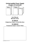
UNINTERRUPTIBLE POWER SUPPLY MASTER MPT from 100 to 200 kVA three phase output w w w .u ps di re ct .c om User Manual .c om ct re di .u ps w w w [email protected] +44 (0)8456 445 002 www.upsdirect.com page 2 / 29 UPS Direct Ltd Column House, London Road Shrewsbury SY2 6NN England 0MNMPTM10RUENUA 00 INDEX 1. STORAGE ........................................................................................................ 7 2. INSTALLATION ROOM ................................................................................ 7 3. PRELIMINARY OPERATIONS .................................................................... 7 3.1 3.2 SETTING UP THE ELECTRICAL SYSTEM................................................ 8 4.1 Protection to be installed: .............................................................................................. 8 4.1.1 4.2 Mains, load and battery connections ............................................................................. 9 4.2.1 4.2.2 4.3 4.4 Residual Current Detector (RDC) ..................................................................................................... 8 .c om 4. Checking the packaging ................................................................................................. 7 Positioning ..................................................................................................................... 7 Configuration with single mains supply ............................................................................................ 9 Configuration with split bypass input.............................................................................................. 10 Remote control and signals .......................................................................................... 10 Checking connections................................................................................................... 13 START-UP PROCEDURE ............................................................................ 13 6. OPERATIONAL CHECK.............................................................................. 13 7. BYPASS FOR MAINTENANCE SWMB ................................................................ 14 8. SWITCHING OFF ............................................................................................... 14 9. SET UP & CUSTOMISATION............................................................................... 14 di re ct 5. .u ps 10. MODES OF OPERATION .................................................................................... 15 10.1 Block diagram .............................................................................................................. 15 10.2 Configuration modes .................................................................................................... 17 On – line .......................................................................................................................................... 17 Standby-on / smart active ................................................................................................................ 17 Standby-off....................................................................................................................................... 17 Stabiliser (without battery) .............................................................................................................. 18 Frequency Converter ....................................................................................................................... 18 w 10.2.1 10.2.2 10.2.3 10.2.4 10.2.5 w 10.3 Emergency work ........................................................................................................... 18 w 10.3.1 Battery operation (not in Stabiliser mode) ..................................................................................... 18 10.3.2 Operation of the bypass supply........................................................................................................ 18 11. MAINTENANCE........................................................................................... 19 12. SPECIFICATIONS ....................................................................................... 20 13. PARALLEL VERSION ......................................................................................... 22 13.1.1 13.1.2 13.1.3 13.1.4 13.1.5 Introduction ..................................................................................................................................... 22 Installation....................................................................................................................................... 22 Initial start up .................................................................................................................................. 24 Modes of operation.......................................................................................................................... 25 Emergency power off (epo) connection ........................................................................................... 29 0MNMPTM10RUENUA 00 page 3 / 29 Thank you for choosing our product. RPS S.p.A. is highly specialized in the development and production of uninterruptible power supplies (UPS). The UPSs of this series are high quality products, carefully designed and manufactured to ensure optimum performance. Symbols used in the manual In this manual, some operations are shown by graphic symbols to alert the reader to the dangerous nature of the operations: .c om Possibility of serious injury or substantial damage to the device, unless adequate precautionary countermeasures are taken. This symbol indicates some important information which must be read with care. di re ct It is recommended to read this part of the manual. .u ps Protective equipment to be worn No maintenance operations must be carried out on the device without wearing the Personal Protective Equipment (PPE) described below. w Personnel involved in the installation or maintenance of the equipment must not wear clothes with wide sleeves or laces, belts, bracelets or other items that may be dangerous, especially if they are metallic. Long hair must be tied in such a way as to ensure that it is not a hazard. w The following signs show the protective equipment that should be worn. The various items of PPE must be selected and sized according to the nature of the hazard (particularly electrical) posed by the equipment. w Accident prevention footwear Protective eyewear Use: always Use: always Protective clothing Helmet Use: always Use: When there are suspended loads Work gloves Use: always page 4 / 29 0MNMPTM10RUENUA 00 Definition of “operator” and “specialized technician” The professional figure responsible for accessing the equipment for ordinary maintenance purposes is defined with the term operator. This definition covers personnel that know the operating and maintenance procedures for the equipment, and that have been: 1. trained to operate in accordance with the safety standards relating to the dangers that may arise where electrical voltage is present; 2. trained to use Personal Protective Equipment and to carry out basic first aid. di re ct .c om The professional figure responsible for the installation and start-up of the equipment, and for any extraordinary maintenance, is defined with the term specialized technician. This definition covers personnel that, in addition to the requirements listed above for a general operator, must also: 1. have been suitably trained by the manufacturers or their representative. 2. be aware of installation, assembly, repair and service procedures, and have a specific technical qualification. 3. must have a background of technical training, or specific training relating to the procedures for the safe use and maintenance of the equipment. .u ps Emergency interventions The following information is of a general nature. First aid interventions w Company regulations and traditional procedures should be followed for any first aid intervention that may be required. Firefighting measures Do not use water to put out a fire, but only fire extinguishers that are suitable for use with electrical and electronic equipment. If exposed to heat or fire, some products may release toxic fumes into the atmosphere. Always use a respirator when extinguishing a fire. w 1. w 2. 0MNMPTM10RUENUA 00 page 5 / 29 GENERAL PRECAUTIONS This manual contains detailed instructions for the use, installation and start-up of the MASTER MPT . Read the manual carefully before installation. For information on using the MASTER MPT , the manual should be kept close at hand and consulted before carrying out any operation on the device. This device has been designed and manufactured in accordance with the standards for the product, for normal use and for all uses that may reasonably be expected. It may under no circumstances be used for any purposes other than those envisaged, or in any other ways than those described in this manual. Any interventions should be carried out in accordance with the criteria and the time-frames described in this manual. .c om PRECAUTIONS AND SAFETY REGULATIONS Refer to the “Safety and Compliance Manual” supplied with the UPS (0MNA141_NE). ENVIRONMENTAL PROTECTION .u ps di re ct In the development of its products, the company devotes abundant resources to analysing the environmental aspects. All our products pursue the objectives defined in the environmental management system developed by the company in compliance with applicable standards. No hazardous materials such as CFCs, HCFCs or asbestos are used in this product. When evaluating packaging, the choice of material has been made favouring recyclable materials. For correct disposal, please separate and identify the type of material of which the packaging is made in the table below. Dispose of all material in compliance with applicable standards in the country in which the product is used. DESCRIPTION MATERIAL Box Cardboard Polythene Accessories bag Polythene w Protective bag w DISPOSING OF THE PRODUCT w The UPS contain electronic cards and batteries which are considered TOXIC and HAZARDOUS waste. When the product reaches the end of its operating life, dispose of it in accordance with applicable local legislation. Disposing of the product correctly contributes to respecting the environment and personal health. No reproduction of any part of this manual, even partial, is permitted without the RPS S.p.A. authorization. The RPS S.p.A. reserves the right to modify the product described herein, in order to improve it, at any time and without notice. page 6 / 29 0MNMPTM10RUENUA 00 1. STORAGE If the UPS is not to be installed immediately it must be stored within the original packaging and protected from moisture and weather. The area used to store the equipment must have the following characteristics: Temperature: -25°÷ + 60°C (-13°÷140°F) Relative humidity: 90% max The recommended storage temperature is between +10° to 30°C (+50° e 86°F). 2. INSTALLATION ROOM PRELIMINARY OPERATIONS 3.1 Checking the packaging re 3. ct .c om The UPS and its battery cabinet are designed for indoor installation. The following points should be observed when choosing the place of installation: • avoid dusty environments; • ensure that the floor is level and able to support the weight of the UPS and the battery cabinet; • avoid sites that are too narrow as this may impede normal maintenance operations; • the ambient relative humidity must not exceed 95%, non-condensing; • avoid positioning in sites exposed to direct sunlight or hot air; • ensure that the ambient temperature, with the UPS operating, remains between : operating temperature: 0 ÷ + 40 °C maximum temperature for 8 hours a day: + 40°C mean temperature for 24 hours: + 35°C Note: - The recommended operating temperature for the UPS and for the batteries life is between 20 and 25°C. To keep the temperature of the installation room within the range indicated above, a system has to be provided to remove the dissipated heat (for the value of the kcal/kW dissipated by the UPS refer to the “SPECIFICATIONS”). .u ps di When you receive the UPS check that the packaging has not been damaged during transportation. Confirm that neither of the two anti-shock/tilt devices fixed to the packaging have been activated. If this has happened follow the instructions provided on the packaging. Be careful when removing the packaging materials so as not to scratch the UPS cabinet. The equipment must be handled with care as it could be damaged if it is dropped or banged. The UPS is supplied with: • user instruction manual • CD-ROM with the UPS management software & communications cable 1000 w w w 1000 RIMOZIONEDELPALLET/ TOREMOVETHEPALLET 3.2 MOVIMENTAZIONE CON IMBALLO / HANDLING WITH PACKING Positioning The air enters the UPS through ventilation grills located in the front door and exit through the fan grills located on the top panel. The following should be taken into account when choosing a position for the UPS: • a space of at least one metre must be kept clear in front of the equipment for start-up/shutdown operations and any maintenance operations that may be required • leave a minimum distance of 60cm between the top of the UPS and the ceiling of the room, to enable adequate circulation of the air exiting the system 0MNMPTM10RUENUA 00 page 7 / 29 • The AC-DC INPUT/OUTPUT cables enter from the bottom of the UPS. Access to the power and auxiliary terminals and the switchgear is from the front. For the mechanical dimension of the UPS refer to the installation diagram supplied with the USER MANUAL The installation diagram identifies: - the position of the holes in the base plate through which the equipment can be bolted to the floor; - the base view to design a pedestal (if the UPS is to be located on a raised floor); - cable entry position; - position of the fans on the top of the UPS. 4. SETTING UP THE ELECTRICAL SYSTEM 4.1 Protection to be installed: - Connection table 160 [A] [A] 218 250 262 315 348 400 436 450 [A] [A] 145 200 174 250 232 315 290 400 [A] 145 .c om BYPASS (**) Current Fuse gG type OUTPUT Rated current 120 ct INPUT Imax (*) Fuse gG type 100 174 232 200 290 di re BATTERY Battery eq. permanent current [A] 294 327 436 540 (*) 100% load, nominal input voltage and battery recharging. (**) On the bypass line into the UPS are not present protection dispositive. External protection must be inserted at the UPS input.. .u ps Ac input On the incoming mains supply of the the UPS, in the distribution cabinet, must be install a overcurrent protections. This protection shall be made with fuse type as shows in the table or with equivalent circuit breaker. For dual incoming supplies, separate protective devices must be installed for the Rectifier and the Bypass inputs. w w w Battery ATTENTION Any battery cabinet must have its own fuses on its output terminals “+” and “-“. Remember that those fuses must be able to open the dc voltage. If using the “Rapid” fuse, type gG/gL NH, the MAXIMUM size of the battery fuse must be below 2 times the nominal battery capacity. If using the “Ultra Rapid” fuse, type aR NH, the MAXIMUM size of the battery fuse must be below 2.5 times the nominal battery capacity. For example: battery type 150Ah we can use 250A gG/Gl or 315A aR. 4.1.1 Residual Current Detector (RDC) A differential switch (RCD) must be inserted into the mains supply input (upstream). The differential switch located upstream must have the following characteristics: - Sensitivity 500mA; - sensitive to d.c and unidirectional pulses (class A or B) - insensitive to transient current pulses - class A or class B - delay greater or equal to 0,1s In the standard version, where there is no isolation transformer in the by-pass line, the neutral input from the mains supply is directly connected to the output from the UPS. INPUT NEUTRAL CONNECTED TO OUTPUT NEUTRAL THE ELECTRICAL SYSTEMS LOCATED UPSTREAM AND DOWNSTREAM OF THE UPS ARE IDENTICAL page 8 / 29 0MNMPTM10RUENUA 00 When operating in the presence of mains supply, a differential breaker (RCD) installed on the input will intervene as the output circuit is not isolated from the input circuit. When operating without mains supply (from battery) the input differential breaker will intervene only if it is able to switch as a result of leakage current without any voltage at its poles (for example a differential breaker with an auxiliary relay is not suitable). However it is possible to install additional differential breakers on the output of the UPS, possibly coordinated with those on the input. To avoid nuisance tripping, earth leakage monitoring devices used in parallel systems must be located at the input of the entire UPS system as shown in diagram B. N A N N UPS N N B N UPS N UPS N UPS N N N Mains, load and battery connections .c om 4.2 N THE FOLLOWING OPERATIONS DESCRIBED IN THIS CHAPTER MUST BE PERFORMED BY TRAINED PERSONNEL. ct THE FIRST CONNECTION TO BE MADE IS THE GROUND/EARTH CONNECTION TO THE TERMINAL MARKED 'PE'. THE UPS CANNOT OPERATE WITHOUT CONNECTION TO THE GROUND/EARTH SYSTEM. di re Before connecting, ensure that that the UPS equipment is totally isolated from any external power sources, battery and mains line, and that all of the UPS switches are open, in particular: - the UPS mains supply input is completely isolated - all of the switches on the UPS: SWIN, SWBY, SWOUT, SWMB, are in the OFF position - the output switch of the battery cabinet is in the open position - always ensure that no hazardous voltages are present by measuring with a multi-meter. .u ps For the power cable connection to the UPS terminal board refer to installation diagram supplied with USER MANUAL. 4.2.1 Configuration with single mains supply w MAINS LINE SWMB w NOTE: The feed must be three-phase with neutral. The UPS cannot work without input neutral (*). SWBY w F - For the installation of the protective devices on the input, refer to the “connection table”. F LOAD SWOUT SWIN UPS BATTERY CABINET +/- (*)The operation without input neutral is admitted only with transformer (delta-star) on the input line . The links between the SWIN and SWBY switches are pre-fitted. The cables must be terminated using pre-insulated crimp terminals and should be connected as shown in installation diagram supplied. 0MNMPTM10RUENUA 00 page 9 / 29 4.2.2 Configuration with split bypass input NOTE: The by-pass supply must be three-phase with neutral. The UPS cannot work without input neutral on the by-pass line (*). SWMB BY-PASS LINE F SWBY SWIN LOAD SWOUT UPS BATTERY CABINET MAINS LINE +/- (*) The operation without input neutral is admitted only with transformer (delta-star) on the input bypass line . .c om F F - For the installation of the protective devices on the input, refer to the “connection table”. Remote control and signals re 4.3 ct - remove the links between mains line and by-pass line The cables must be terminated using pre-insulated crimp terminals and should be connected as shown in installation diagram supplied. N A P Q M C I D J2 E J6 B J1 L H F G w w w .u ps di The door must be opened to access the interface connectors: ABCDEFGH- PARALLEL (optional) EPO (emergency power off) REMOTE RS232-1 RS232-2 SLOT 2 SLOT 1 REMOTE ALARM (optional) page 10 / 29 I- REMOTE ALARM (optional) L- MODEM (optional) M- Battery temperature sensor (optional) N- UGS (optional) O- 230V auxiliary output P- aux SWOUT Q- aux SWMB 0MNMPTM10RUENUA 00 A – PARALLEL board (optional) Parallel UPS connection, the UPS can be connected in parallel in order to increase the total output power available. Up to 8 units can be connected in parallel; it is advisable to connect units of the same power. For the connection of parallel units refer to the appendix. B - EPO connector (Emergency Power OFF) When the jumper on the EPO connector is opened the UPS output voltage is switched off. The UPS is factory supplied with the EPO connector in short-circuit. By using an EPO button or contact to open this connection, it is possible to switch off the UPS output. NOTE: By removing only the supply to the UPS, for instance by opening the UPS input switch, this will only result in the UPS supplying the load from the 1 batteries and therefore the output voltage will still be present. BATTERY LOW .c om - BATTERY DISCHARGING C - REMOTE This connector provides: Nr. 1 aux power 12Vdc 80mA(max) (pin 10, 11) Nr. 3 Volt free alarm contacts Nr. 2 command for turning the INVERTER and UPS off. The pin arrangement of the connector is as follows (see figure opposite): BATTERY LOW BATTERY DISCHARGING BY-PASS/FAULT The contact positions shown are without alarm (NORMAL OPERATION). The relay contacts can sustain max a current of 0,5A-42V. ct + BY-PASS/ FAULT inverter off re 12V 2 3 4 5 6 7 8 9 10 11 12 REMOTE COMMAND • w .u ps di INVERTER OFF - BY-PASS with INVERTER OFF command is possible by connecting pin 11 to pin 12 (for at least 2 seconds). 1. If the UPS receives the INVERTER OFF command during "NORMAL OPERATION" mode, the UPS will switch the supplied load onto the BY-PASS supply (the load will be unprotected from any mains failures). 2. If the UPS receives the INVERTER OFF command during "BATTERY OPERATION" mode, the UPS will switch off (load not supplied) For both instances shown above, if the jumper is maintained when the mains supply returns the UPS will continue to operate on the by-pass supply. However, if the jumper has been removed, the UPS will start up in "NORMAL OPERATION" mode w w RS232 Two connectors for the connection of RS232 are available. The default factory set transmission protocol is as follows: 9600 baud, -no parity, -8bit, -1 stop bit. The transmission speed can be changed from 1200 to 9600 baud via the CUSTOMISING menu on the control panel. The recommended transmission speeds for various distances are UPS 1 as follows:9600(baud) - 50m, 4800 - 100m, 2400 - 200m, 1200 1 1 1 2 2 2 2 - 300m 3 3 3 3 computer 4 4 4 4 Always use shielded cable, only connect the shield to the housing 5 5 5 5 6 6 6 6 of the MODEM or PC connector, AWG22-AWG28. 7 8 9 female femmina DB9 D - DB9 female marked RS232-1 For the computer connection use the RS232 standard cable. For the modem connection see the diagram. 7 8 9 male maschio DB9 7 8 9 female femmina DB9 7 8 9 male maschio DB9 RS232-1 UPS 1 2 3 4 5 6 7 8 9 female femmina DB9 1 2 3 4 5 6 7 8 9 male maschio DB9 1 2 3 4 5 6 7 8 9 male maschio DB9 1 2 3 4 5 6 7 8 9 Modem female femmina DB9 RS232-1 0MNMPTM10RUENUA 00 pag. 11 / 29 UPS E - DB9 male marked RS232-2 For the modem connection use the RS232 standard cable. For the computer connection see the diagram. 1 2 3 4 5 6 7 8 9 male maschio db9 1 2 3 4 5 6 7 8 9 1 2 3 4 5 6 7 8 9 female femmina db9 male maschio db9 1 2 3 4 5 6 7 8 9 Modem female femmina db9 RS232-2 UPS 1 2 3 4 5 6 7 8 9 male maschio DB9 1 2 3 4 5 6 7 8 9 1 2 3 4 5 6 7 8 9 female femmina DB9 female femmina DB9 1 2 3 4 5 6 7 8 9 Computer male maschio db9 di re ct .c om RS232-2 F, G – SLOT 2 and SLOT 1, may be installed the following electronic cards - NETMAN PLUS 102 card (SLOT 1 - main or SLOT 2 - aux ) This device enables UPS monitoring and management across a LAN using the following network communication protocols: TCP/IP (Compatible with Powershield and Watch and Save); SNMP (for communication with NMS or PowerNETGuard software); HTTP (to view monitoring status via a web browser); TFTP (to configure or update the system over the net); The main function is to integrate the UPS into the net LAN, thus guaranteeing a high degree of reliability of the communication with the servers. - MULTICOM 302, 352, card (SLOT 1 – main or SLOT 2 - aux) This device can be used to: - add two serial RS232 ports onto a UPS; - MultiCom can be used to monitor the UPS via the MODBUS/JBUS protocol on RS485. .u ps N.B. The ETHERNET or MULTICOM ports are internally connected to the RS232 ports (D & E), the use of these cards prevents the use of the corresponding RS232 port: the use of the SLOT 1 (main) prevents the use of the RS232-2, the use of the SLOT 2 (aux) prevents the use of the RS232-1. w H, I - REMOTE ALARM (Nr. 2 optional card) Provided with 6 output alarm volt free contacts (programmable from the control panel), 2 input (programmable from the control panel) and 1 auxiliary 12V dc voltage, max. 100 mA. w L - MODEM (optional) Enables communications between the UPS and the software or monitoring station over a phone line. N.B. the Modem ports are internally connected to the RS232 ports (D & E), the use of these items prevents the use of the corresponding RS232 port. w M - Battery temperature (optional) The UPS is supplied with a connection point to connect an external battery temperature sensor kit. This enables the microprocessor to monitor the temperature and regulate the maintenance and charge voltage value of the batteries. N- UGS - Dual Bus System (optional) Two independent systems can be configured in Dual Bus with a single or separate power source. The synchronisation option (UGS) keeps the outputs of the two systems constantly synchronised, regardless of the input variations and when the system is powered by the battery. Each system comprises up to a maximum of 4 parallel UPSs. This system has been designed for configurations that use the STS (Static Transfer Switch) since it guarantees switching from one continuous source to the other without disturbances to the loads. O- aux output 230V-1A from the UPS output P-Q- SWOUT e SWMB aux. To connect external switch auxiliary. page 12 / 29 0MNMPTM10RUENUA 00 4.4 Checking connections After connecting all of the INPUT/OUTPUT and terminal wires to the UPS, before repositioning the switch covers, confirm that: • all of the input/output terminals are tightly secured; • all fuse holders have the correct fuses inserted and are in the closed position; • the input/output protection wire (yellow/green earth wire) is correctly connected; 5. START-UP PROCEDURE .c om After completing the electrical connection as indicated above and replacing all of the previously removed panels, proceed to start up the UPS as follows: - open the UPS door to gain access to the input and the output switches. - close the switches located on the mains supply input distribution panel, where used - close the battery cabinet switches (check the polarity of the connection first), - close the following UPS switches (the identification is provided on the switch cover panel): SWIN (input switch), SWBY (by-pass line switch), SWOUT (output switch). NOTE: the SWMB switch (maintenance bypass switch) must be left open during normal operation. The SWMB is only closed when it is necessary to bypass the UPS thus connecting the output load directly to the incoming mains supply, therefore allowing the UPS to be maintained. X000YZZ UPS model output power [kVA] output frequency: Y = _ output 50Hz Y = A output 60Hz configuration mode: Z = __ output frequency = input frequency Z = _ C frequency converter with battery Z = KS frequency converter without battery Z = _N standby on Z = _F stand by off Z = S stabiliser Z = P or p parallel version Z = B or b parallel version with only one battery .u ps X 000 Y di re ct After carrying out the above-mentioned operations, you will immediately hear the hum of the fans, and for approximately one minute, the noise of the buzzer. Press key 1 twice, to select the language and then press key 8, to return to the main menu. The message NORMAL OPERATION will appear. Manually perform a battery test: by pressing key 3 on the control panel, followed by key 2 (BATTERY TEST). When the test has finished and the UPS is operating correctly, with the battery connected, the green IN LED (INPUT) and the green OUT LED (OUTPUT) lights should be illuminated steady. The message NORMAL OPERATION should appear on the first line (top) of the display panel. The model of the UPS, according to the following code, will appear on the second line (bottom) in the left-hand corner: 6. w w w Z OPERATIONAL CHECK After completing the start-up operations and waiting a few hours to allow the batteries to charge, with the UPS in normal operation, a Mains failure simulation may be carried out by switching the incoming mains supply off. Once the mains supply has been switched off you will immediately hear the sound of the buzzer (if activated), during this the green OUT LED and yellow BATTERY LED will be illuminated constantly on the control panel. Confirm that the protected load is working; during this operation the power supplied to the protected load is being supplied by the energy stored within the batteries. After a few minutes of battery operation the UPS can be returned to normal operation by re-connecting the mains supply input. Once in normal operation mode the green IN and OUT LED’s will be illuminated constantly on the control panel and the batteries will be recharged automatically. 0MNMPTM10RUENUA 00 page 13 / 29 7. Bypass for maintenance SWMB Note: for the UPS in parallel configuration see the “by pass for maintenance” paragraph in the “Parallel version” chapter. Carry out the following series of operations to put the UPS into maintenance bypass whilst maintaining the power to the load: 1. Ensure that the UPS is indicating BYPASS or NORMAL OPERATION 2. Close the SWMB switch (the control logic will automatically disable the inverter). 3. Open all of the other switches (SWIN, SWOUT, SWBY) and the battery cabinet switches. Only the SWMB switch remains closed (maintenance bypass supply). The control panel will be off and the connected load will be supplied via the bypass line (during maintenance). NOTE NOTE: After disconnecting the mains (AC) and battery (DC) supplies, authorised service personnel must wait at least ten minutes for capacitor bleed off before attempting to gain internal access of the UPS. During this mode the connected load is not protected by the UPS, therefore any disturbances or failures will be passed onto the connected load. .c om Once the maintenance operations have been completed, to restart the UPS: close SWIN, SWOUT, SWBY and the battery cabinet switches, wait for a few seconds for the UPS to start, and then open the SWMB. The UPS will automatically return to NORMAL OPERATION. 8. re ct WARNING: do not use SWMB switch when the UPS is setting as frequency converter. NOTE: in order to prevent switch use it should be blocked with a padlock. Switching off .u ps di This operation must only be carried if the load is to be switched off. In a parallel UPS system each step of the procedure must be performed for each UPS module before carrying out the next step. The following operations will switch off the power to the connected loads. open SWOUT, output switch; open SWIN, rectifier input switch; open SWBY, bypass line input switch; open the external battery circuit breaker; The load is now be switched off. After a few seconds the signalling control panel will also be extinguished. Confirm that no voltage exists on the terminals using a multimeter. Set up & customisation w 9. w NOTE. neutral cable is not interrupted by the switches (the neutral input from the mains supply is directly connected to the output from the UPS). w By pressing key 3 from the main MENU ("COMMANDS"), followed by key 5 ("CUSTOMISING") and then by inserting the customisation access code 436215 using the CONTROL PANEL, it is possible to modify the operational mode of the UPS (refer to the "MODES OF OPERATION" paragraph) and to alter the pre-set electrical configuration of the various fields. It is possible to customise the following parameters: - NOMINAL OUTPUT VOLTAGE; - BYPASS line input voltage and frequency tolerance; - BYPASS line input in STANDBY-ON mode accepted voltage and frequency tolerance; - BATTERY configuration and low battery pre-alarm for the end of the battery discharge; - UPS switch to the bypass line when the output power is less than the set value (AUTO-OFF power); - scheduled daily switch off (AUTO-OFF time); - RS232-1 and RS232-2 port transmission baud rate; - UPS identification number. To make changes to the configurable fields refer to the information shown in the ”key menu 3,5,code,…..” in the Control Panel paragraph. page 14 / 29 0MNMPTM10RUENUA 00 0MNMPTM10RUENUA 00 External Battery Input mains Standard Jumper on terminal board Bypass line input separate SWIN Signallings and command panel Backfeed protection Control circuit with microprocessor SWOUT SWMB 1-9 1-9 DB9 male 1-12 13 14 DB9 female .c om Static switch ct re di Inverter .u ps w Rectifier SWBY w w RS 232-2 line ----------- for Modem RS 232-1 line ----------- for PC Remote control and signals EPO Output 10. Modes of operation 10.1 Block diagram page 15 / 29 Block diagram components The UPS consists of the following subassemblies: RECTIFIER .c om The rectifier represents the input stage and transforms the alternating voltage from the mains supply in direct voltage. From the display panel can be programmed start black out up of the rectifier in particular: input - the start up delay t0 –t1 from 0 to 120s (that allows to a not contemporary starter more UPS voltage connects you to the same mains) - power walk-in t1 – t2, from 0 to 120s setting (can be used a smaller Motor Generator size in UPS setting input). input current The functions carried out by the rectifier are the following: supplying the inverter with direct current. automatically charging the battery. optimize the input power factor with a automatic battery charge system. t1 t t2 ct t0 t .u ps di re The cyclical battery charging is done in two phases. The first phase recharge the batteries with limited current and increasing voltage (to the value of charge voltage “Vbat_max”). This phase comes maintained until to the full charge of the battery (Batt=100%Ah), that is checked through the measure of the input current in the battery. In the second phase, with battery full charge, it is proceeded to deactivate the charge of the battery so as to obtain the zero setting of every residual current in battery to the aim to lengthen the battery life and the predisposition of the rectifier for the optimization of the input power factor. Moreover every day the system carries out a automatically cycle in order to verify the state of charge and reintegrate the normal self discharge of the battery. w BATTERY (EXTERNAL) The batteries form the energy reserve to power the load in the absence of the mains power supply to the UPS. They are housed in dedicated cabinets. The battery cabinet must be supplied with the electric protection and sectioning dispositive (automatic breaker or switch with fusibles). w w INVERTER This represents the output stage and converts the direct voltage from the RECTIFIER or BATTERY into a stabilised sinusoidal alternating voltage. The inverter output and the load are isolated from the input and battery. The inverter continually operates and the load connected to the output of the UPS is always supplied by the INVERTER (in NORMAL OPERATION). STATIC SWITCH This device enables the instantaneous automatic or manual switching of the power supply from the protected line (INVERTER output) to an unprotected line (BY-PASS supply) or vice versa. Back feed protection is inserted as standard in the SCRs. SWMB Maintenance bypass switch, by closing the SWMB and opening all of the other switches SWIN, SWBY, SWOUT the UPS is isolated whilst maintaining a supply to the load. This operation is necessary when you have to carry out maintenance operations inside the equipment, without disrupting the power supplied to the load. With the SWMB closed and all of the other switches open, there is no voltage inside the equipment (voltages are present only in the terminal board and in the switches area , N.B. the neutral conductor is not interrupted.) The manual bypass line is sized for the nominal power of the UPS. page 16 / 29 0MNMPTM10RUENUA 00 10.2 Configuration modes UPS The UPS is pre-factory configured to start in On-line mode. In order to configure the various operation modes refer to the “CUSTOMISING” paragraph in the Control Panel section. BY STATIC SWITCH INPUT SWIN, SWBY, SWOUT close and SWMB open. AC / DC OUTPUT OUT INVERTER IN BATT BATTERY .c om The UPS can be configured for various modes of operation: 10.2.1 On – line When the incoming mains supply is present the connected load is supplied by the inverter which takes power from the mains supply via the rectifier. The Rectifier also charges and maintains the connected batteries. When the mains supply fails the connected load remains supplied by the inverter which now takes the power from energy stored in the batteries (battery operation). ct 10.2.2 Standby-on / smart active di re When the Standby-On is active the letter “N” is present on the second line of the display panel, next to the UPS model, in the MAIN MENU. When Smart Active is set on the first line of the BASE MENU’ is show SMART A and the letter “M” is present on the second line of the display panel. w w w .u ps In standby on or smart active mode the load is supplied from the bypass line (if present), if a problem or fault occurs with the bypass line the load is immediately transferred onto the output of the inverter. During Standby-On mode the inverter to bypass line transfer time can be configured from between 0 to 180 minutes (delayed). For the transfer to occur the bypass supply must remain within the accepted tolerance for the duration of the time set. In Standby-On mode the RECTIFIER remains operational and maintains the battery charge. If the BYPASS supply voltage or frequency exceeds the excepted tolerances, the load is automatically switched onto the output of the INVERTER. The Standby-On mode operation reduces the energy lost by the system (higher efficiency). Before enabling this function confirm that the connected load can accept an interruption in the supply of between 2-5 ms in the event of a mains supply failure. During Smart Active mode the UPS will automatically switch between the On-Line or Standby-On modes, the mode of operation selected is dependent on the quality of the incoming mains supply. In order to configure the operation of the Smart Active mode, refer to the “OPERATION IN SMART ACTIVE CUSTOMISING”. Once the Smart Active mode is enabled the bypass line is monitored for a few minutes. After this time if the value of the input voltage and frequency remains within the accepted tolerances the output is automatically switched onto the bypass supply. If the input supply is not within the accepted tolerances the load remains supplied by the inverter. The UPS will monitor the incoming supply and if the supply remains within the accepted tolerances for more than one hour the load will be switched onto the bypass supply. The benefit of these operation mode is the efficiency improved up to 98%. 10.2.3 Standby-off When the Standby-Off mode is active the letter “F” is present on the second line of the display panel, next to the UPS model, in the MAIN MENU. In Standby-Off mode when the mains supply is present the output from the UPS is switched off. The RECTIFIER remains operational and maintains the battery charge. The connected load is only supplied when the input voltage fails (start up within 500ms). If the mains supply voltage or frequency exceeds the acceptable limits, the connected load is automatically supplied by the INVERTER output. Once the voltage or frequency returns to within the acceptable limits the UPS will return to Standby-Off mode. 0MNMPTM10RUENUA 00 page 17 / 29 10.2.4 Stabiliser (without battery) When the Stabiliser mode is active the letter “S” is present on the second line of the display panel, next to the UPS model, in the MAIN MENU. When the mains supply is present the connected load is supplied. The connected load is supplied by the stabilised inverter output which takes the necessary power from the mains supply via the rectifier. No batteries are connected and in the event of the mains supply failing the connected load will be switced off. 10.2.5 Frequency Converter When the Frequency converter mode is active the following letters shown below are present on the second line of the display panel, next to the UPS model, in the MAIN MENU (depending on the method of operation): A C for 60Hz output converter with battery AKS “ “ without battery C for 50Hz output converter with battery KS “ “ without battery .c om When the mains supply is present the connected load is supplied. The connected load is supplied by the stabilised inverter output which takes the necessary power from the mains supply via the rectifier. The bypass line is disabled and if no batteries are fitted the connected load will be switched off if the supply fails. ct WARNING: do not use SWMB switch when the UPS is setting as frequency converter. NOTE: in order to prevent switch use it should be blocked with a padlock. 10.3 Emergency work re - BATTERY OPERATION (not in STABILISER MODE); - BYPASS OPERATION (from the mains supply); - MAINTENANCE BYPASS (SWMB). di 10.3.1 Battery operation (not in Stabiliser mode) w w w .u ps The UPS switches to battery operation when the incoming mains supply fails, or when the incoming mains supply is not within the acceptable operational tolerance for the UPS (under or over voltage and frequency). During this mode of operation the energy required to supply the power to the connected load is taken from the previously charged batteries. The UPS display panel provides an estimated battery autonomy time which is calculated on the basis of the power being delivered to the load and the charge status of the batteries. The value displayed is an estimation which will change depending on the value of the connected load during the discharge. It is possible to increase the battery autonomy by removing some of the connected equipment, therefore reducing the load applied. When the remaining time falls below the preset value for the LOW BATTERY alarm, the frequency of the buzzer will increase and the yellow BATT led will flash. During the LOW BATTERY condition it is advisable to save any work or stop any processes that can be affected if power to these loads is lost. Once the batteries become exhausted the UPS will be automatically switched off and power to the connected load will be disconnected. When the mains supply returns the UPS will automatically switch on and recharge the batteries. NOTE. The UPS cannot be started from battery. 10.3.2 Operation of the bypass supply This can either be a temporary or permanent state caused by an overload or fault;.. The UPS can switch to this condition (during this state the load is not protected if a mains failure occurs) for one of the following reasons: - BYPASS command active (manual or automatic); - Excessive load on the output (overload) of the UPS; refer to the “ALARM MESSAGES” paragraph in the “SIGNALLING PANEL FUNCTIONS” section; the UPS return in NORMAL OPERATION automatically after that you remove the overload condition - UPS fault (in the case of a fault contact the service centre). On the control panel, the yellow BYPASS LED will be illuminated steady if a command is present, and will flash if an overload or fault has caused the bypass. If the UPS is overloaded you will have to intervene to reduce it. page 18 / 29 0MNMPTM10RUENUA 00 11. MAINTENANCE The UPS have been figured out and realized in order to last for a long period working in tough and strict conditions as well. Anyway they are high power equipment which need to be periodically checked up. In specific some components as batteries, fans and in some cases electrolytic capacitors have their own life cycle that’s one more reason to make a check up on this parts periodically and eventually replace them. Therefore you are invited to plan an estimated maintenance program, which will be looked after from a specialized and authorized staff. The RPS S.p.A. customer care service stays at your disposal to show you the several personalized options you can get for your estimated maintenance. CAUTION .c om Maintenance inside the UPS should only be done by qualified personnel and trained by the manufacturer. The UPS system is designed to supply power EVEN WHEN DISCONNECTED FROM THE MAINS SUPPLY. High voltages are present inside the equipment even when the input and battery switches are open. After disconnecting the mains (AC) and battery (DC) supplies, authorised service personnel must wait at least ten minutes for capacitor bleed off before attempting to gain internal access of the UPS. Preventive maintenance Carry out the following steps periodically: di - ct - Ensure that the air inlets (the grill on the front of the door and in the bottom of the cabinet) and the air outlets (on the top of the UPS cabinet) are not blocked or obstructed. Ensure that the UPS is operating normally (the display panel shows “NORMAL OPERATION”). If an alarm is present consult the user manual for an explanation after that, contact the service centre. Confirm that environmental conditions for the UPS are within the parameters shown in SPECIFICATIONS paragraph. re - .u ps Battery maintenance The UPS automatically checks the battery efficiency every 24 hours and raises an alarm if it detects a lower efficiency than that calculated on the basis of the memorised capacity (refer to key menu 3.2 BATTERY TEST). The battery life will depend on the operating temperature and the number of charging and discharging cycles performed w w The battery capacity is not constant and will increase after a few charging and discharging cycles, it will remain constant for several hundred cycles, then it will finally decreases. Battery maintenance should include: - Maintaining the operational temperature in the range of 20-25°C. - During the first month of use perform two or three charge-discharge cycles. - After the first month of use perform this operation every six months. w Since the batteries are an energy source in themselves, opening the Battery Circuit Breaker does not de-energise the voltage within the batteries. DO NOT ATTEMPT TO ACCESS ANY INTERNAL AREA OF THE BATTERIES YOURSELF. THE VOLTAGES ARE ALWAYS PRESENT IN THE BATTERIES. If you suspect that the batteries are faulty, you should contact the service centre. CAUTION Contact the service centre for battery maintenance. Any battery replacement should be done by qualified personnel. Batteries that have been removed/replaced must be taken to a specialised disposal and recycling facility. The batteries are classified as toxic waste by law. 0MNMPTM10RUENUA 00 page 19 / 29 12. SPECIFICATIONS [kVA] [kW] [mA] leakage current max.: remote signalling: standard: optional: operating temperature: maximum temperature for 8 hours a day mean temperature for 24 hours relative humidity at +20°C cooling: maximum operating altitude: 120 120 108 160 160 144 200 200 180 500 three volt free contacts (battery low, battery discharging, by-pass/fault), aux output 12Vdc 80mA EPO (emergency power off), Nr.2 x RS232 interfaces parallel, 2 x netman plus or multicom cards 2 x remote alarm cards, modem, battery temperature sensor. 0 ÷ + 40 °C + 40°C + 35°C 20÷90 % forced ventilation 1000 m at rated power An (-1% An for each 100m over 1000m) max 4000m 65 dBA 68 dBA from the bottom re ct acoustic noise, as measured at 1m from the front of the equipment: input cable : 100 100 90 .c om SYSTEM rated power: w w w .u ps di RECTIFIER 100 120 160 200 rated voltage: [V] 400V 3 phase voltage tolerance: -25% +20% (-10% +20% for battery recharge) rated frequency: [Hz] 50 / 60 Hz auto sensing frequency tolerance: [Hz] 45 ÷ 65 rated input current (*): [A] 176 211 279 349 power walk-in 0-100% 0÷120s (configurable) power walk-in delay timer 0÷120s (configurable) standard battery type: lead sealed blocks (12V)/ element number (lead sealed): 33 / 198 battery rated voltage: 396 V ripple voltage: < 1% static stability of the rectifier output voltage: ±1% maximum recharge battery current at: [A] nominal load 20 25 35 45 load 90% 40 50 65 80 load 80% 60 75 100 125 load ≤ 50% 80 95 125 155 current distortion, power factor (THDV < 2%) (*): < 25%, ≥ 0,9 MASTER MPT version < 5 %, ≥ 0,9 MASTER MPT HC (*) load 100%, rated input voltage, and full charge battery. page 20 / 29 0MNMPTM10RUENUA 00 [kVA] [kW] [V] [A] 100 100 90 145 [Hz] 200 200 180 290 .c om ≤ 2% ≤3% ± 1% ± 1% ±1% as EN 62040 - 3, class 1 ± 0,05 % ±2 % ( configurable ± 1 ÷ 6 % from the control panel) 1Hz/s ct 1,1 for 60 minutes, 1,25 for 10 minutes, 1,5 per 1 minute 200% rated power for 7” 1,5 In for 1s 3 In for 1s di Linear load: Non linear load (reference load EN62040-3): output voltage static stability: phase voltage dissymmetry with balanced load: line voltage dissymmetry with 100% unbalanced load: stability voltage at transient state (load 0 to 100%) frequency stability: without synchronisation with synchronisation frequency slew rate three-phase transient power overload: [Power/power rating] single-phase transient overload: short circuit current phase-phase (**): short circuit current phase-neutral (**): (**) without bypass line 120 160 120 160 108 144 400 (380 – 415) 3 phase + N 174 230 360 ÷ 420 V 50 / 60 sinusoidal re INVERTER OUTPUT rated power p.f. 0,9 inductive: active power pf 1: rated voltage: rated current (with 400V output)): phase voltage setting: rated frequency: wave form: output voltage distortion 100 145 120 160 200 174 232 290 400 (380-415) 3 phase + N ±15 % (configurable ± 10 % , ± 25 % from the control panel) 50 / 60 ±2 % (configurable ±1 ÷ ± 6 % from the control panel) 2 ÷ 5ms w w .u ps BY PASS LINE rated output current (with 400V output): [A] rated voltage: [V] input voltage tolerance: rated frequency: [Hz] frequency tolerance: “STAND-BY ON” (by-pass to inverter) transfer switch time: i²t SCR bypass (25°C, 8÷10ms) [A²s] overload [Power/power rating] w current admitted (for short time): I/In standard: 0MNMPTM10RUENUA 00 1s 500ms 200ms 100ms 10ms 145 k 405 k 1,1 for 60 minutes, 1,25 for 10 minutes, 1,5 for 1 minute 12 10 7,5 9,5 13 11 8 10,5 14 13 9,5 12.5 16 14 10,5 13,5 22 20 15 19,5 Backfeed Protection; bypass line separable page 21 / 29 13. Parallel version 13.1.1 Introduction 13.1.2.1 J4 J5 J3 J6 J2 J1 Parallel signals RJ45 flat-adapter .u ps 13.1.2 Installation di re ct .c om It is possible to connect multiple UPS systems parallel in order to increase the reliability and/or the total output power availability. It’s advisable to always connect units of the same power rating. When using multiple UPS, the connected load is shared amongst the individual systems, this method increases the overall reliability of the supply to the connected load as the load is being supplied from multiple systems instead of a single system. The reliability is further increased by adding an additional redundant UPS; therefore if one of the UPS systems fails the load will continue to be supplied by the remaining systems without any disruption being caused. A redundant system is created by adding an additional UPS to the minimum number of UPS necessary to supply the load, thus if a unit is disconnected or fails the remaining units will adequately support the load. The UPS connected in parallel are controlled via a card, this card exchanges data and synchronisation information which ensure a stable and controlled operation. The information exchange between the UPS systems is via a data cable which forms a closed loop connection. The closed loop connection creates a redundant signal cable which enables all of the UPS systems to continue to operate even if one of the cables are damaged, an added benefit of this system is that it allows the hot insertion or hot disconnection of a UPS, without the need for down time. Each UPS uses its very own dedicated controller that continuously communicates with the other systems to ensure perfect operation and management of the power. The data cable is used to transmit all of the necessary information from the "Master" UPS to the "Slave" UPS, the data cables are fully opto isolated, this provides total electrical isolation between the control systems. When the parallel system is initialised the first UPS to start assumes the roll of the “Master" which then takes control of the "Slaves". If the "Master" unit malfun-ctioned the control is automatically switched over to one of the "Slaves" which becomes the new "Master". The system requires (in standard form) that every unit connected is provided with its own battery, however it is possible to configure the UPS systems to share a common battery (by inserting the appropriate code on the control panel). - Parallel signals RJ45-flat-adapter card w may be used two RJ45 card type with different switch (type 1 or 2) Type 2 J1 w Type 1 w J2 Led external connection RJ45 type external connection RJ45 type internal connection side connector (type 1) side led (type 2) side led (type 1) side connector (type 2) lit switch in Start position off switch in Cont position page 22 / 29 J2 J3 SW1 SW1 LED LED side led J1 J2 J3 SW1 J1 J3 side connector Start position Cont position 0MNMPTM10RUENUA 00 13.1.2.2 Firmware update All of the UPS connected together must have the same firmware release. Press key 7 on the control panel to display the firmware release. 13.1.2.3 Signal connection Example of the signal connections of a single UPS UPS 1 C B B E D A Example of the signal connections between two UPS UPS 2 D E B B E D LED (lit) UPS1, LED (off) UPS2 SW1 Start position UPS1, SW1 Cont position UPS2 A A Example of the signal connections between three UPS C UPS 2 UPS 3 B B E D A A A di Only an additional UPS PARALLEL CABLE is required to connect more UPS. UPS 1 ct LED(lit) UPS1, LED(off) UPS2 and UPS3 SW1 Start position UPS1, SW1 Cont position UPS2 and UPS3 re D E C UPS UPS parallel cable RJ45 connectors Parallel signal RJ45-flat-adapter card lilted (lit) SW1 Start position .c om A B C D E .u ps The connectors must remain connected even if the UPS is switched off w w w 13.1.2.4 Power connection “input/output UPS” AC To calculate the dimensions of the required cabling refer to the “SETTING UP THE ELECTRICAL SYSTEM” section. The dimension of the cables must be rated for the individual units being connected. Connect the input to each of the UPS as follows: - Connect the mains supply phases L1, L2, L3 and N to the inputs of each of the UPS. MAINS (A) Connect the UPS output as follows: - Connect the output load phases L1, L2, L3 and N to the outputs of each of the UPS. a1 a2 a3 IN (B) IN (B) IN (B) 1 1 UPS 2 2 UPS UPS33 OUT (C) c1 OUT (C) OUT (C) c2 c3 The following diagram shows an example of a parallel system connection using three units. A) B) C) D) Mains supply UPS input terminal UPS output terminal Load a1,a2,a3,c1,c2,c3) D 0MNMPTM10RUENUA 00 Cable length When carrying out the power connections to the UPS, it is important to adhere to the following (this is to ensure equal power sharing during bypass operation): page 23 / 29 The sum of the total length of the input and output cables must be the same for each unit. Therefore: a1+c1 = a2+c2 = a3+c3 N.B. If you want to connect a isolators on the output of each UPS refer to paragraph “additional sectioning”. 1) Individual batteries”standard connection” BAT) UPS battery input connection OUT) UPS output connection 1,2,3) Parallel UPS. Each UPS has a battery connected - - - 13.1.2.6 - - - Battery Connections - - - 13.1.2.5 BAT BAT BAT 1 2 3 OUT OUT OUT .c om - - - 13.1.2.7 A BAT 1 2 3 OUT OUT OUT ct BAT Star connection BAT) UPS battery input connection OUT) UPS output connection 1,2,3) Parallel UPS. A) Battery switch cabinet terminal board (optional) re BAT 2) Single battery (enter code “467123”) .u ps di The battery cables must be rated to suit the individual UPS Use this solution for a high battery discharge current. w Series connection BAT) UPS battery input connection OUT) UPS output connection 1,2,3) Parallel UPS. A,B,C) Battery connections A B C BAT BAT BAT 1 2 3 OUT OUT OUT w w Wire “A” must be sized for the total UPS battery current (UPS1 current + UPS2 current + UPS3 current) Wire “B” must be sized for the UPS2 current + UPS3 current Wire “C” must be sized for the UPS3 current Use this solution for a low battery discharge current. - - - 13.1.3 Initial start up WARNING: When closing the SWMB always observes the following precautions: - Do not close the SWMB on a UPS that is switched off and in parallel with other units in normal operation. This operation can cause the UPS to fail, and create a dangerous voltage on the UPS output. The SWMB can be closed when a UPS is in "Normal Operation" provided that the information in the paragraph "FUNCTIONING MODES" is followed. It is possible to lock the SWMB switch to prevent unauthorised use. Before starting the parallel system for the first time it is necessary to carry out several tests in order to verify that the connection between the UPS are correct. A) Check that all of the switches (SWIN, BATTERY, SWBY, SWOUT and SWMB) on each UPS are open. page 24 / 29 0MNMPTM10RUENUA 00 B) Close the SWMB on a single unit and confirm that on the other units the: Voltage between the corresponding input and output terminals of each UPS is <2Vac. If the voltages exceeds this value, locate and correct the error. Following this test open the SWMB. C) Switch on UPS1 by closing SWIN, BATTERY, SWBY and SWOUT and wait until the message “NORMAL OPERATION” is displayed. D) On the remaining units close the SWIN, SWBY and BATTERY. E) Confirm that all of the UPS in the parallel system are on. ct .c om F) If only one battery system is to be connected Confirm that on the second row of the display panel the “X” character is: Example: “type UPS”, “X” OUT=YYY%VA, BATT=YYY%Ah, 5=ON(or OFF) Note: For UPS where the “X” character is a capital B or P means that the unit is the master unit. The “X” character on the master unit denotes: X = B, a capital B is displayed if the system has been configured for a parallel battery and the appropriate code has been entered and the total battery capacity has been set (see below). X = P, a capital P is displayed if the system has individual battery packs connected, therefore if a parallel battery system is to be used the parallel battery code needs to be entered, to do this press key 3, followed by 5, and then enter the code 467123 (to disable the parallel function repeat the key sequence). This code only has to be entered into one of the UPS as the data link cable will automatically update the remaining units, once the code has been entered the display panels of the remaining units will display a lower case b or p meaning that these are the slave units. Only insert the value of the single battery capacity. This operation is only required to be performed on the Master unit which will send the information through to the other systems automatically. .u ps di re G) Close the SWMB on UPS 1 and confirm that all of the UPS systems switch to bypass operation (the by-pass LED on UPS 1 will flash and on the remaining units the LED will light steady), open the SWMB and wait few seconds and confirm that UPS1 switches to “NORMAL OPERATION”. If all of the checks are successful close the SWOUT on all of the units. Fit the locking device onto all of the SWMB switches to prevent unauthorised operation. H) Confirm that all of the UPS are reporting “NORMAL OPERATION”. I) One minute after the last UPS was switched on, confirm that with no load connected the output load on each UPS is < 3% W o 5% VA. L) Once the load is connected to the output, confirm that the power shared between each UPS is within the range of +/2%. Testing the bypass operation w w w Connect a load to the output of the system, ensuring that each UPS indicates a load of greater than 5%. Switch the UPS into bypass operation from the control panel by pressing key 3 followed by 6, and then by entering the bypass sequence 47263 as shown on the display panel. After a couple of seconds all of the UPS will switch to by-pass operation, whilst in bypass verify that the load percentage on each display panel is even to or less than 5%. Whilst operating on the by-pass supply the power being shared between the UPS will depend upon the length of the cables, therefore it is preferred to maintain identical cable lengths. If it is discovered that the load is unbalance when operating on the bypass supply, the overall power of the system will have to be degraded. For example if the unbalance during by-pass is approximately 20%, then the maximum available power from the system will have to be reduced to 90% of the total nominal power. 13.1.4 Modes of operation Multiple UPS connected in parallel to provide a high power capacity. Within a system comprising of more than one UPS connected in parallel there is only ever one MASTER unit, with the remaining units operating as slaves. The UPS are all identical, however at the initial switch on the system will automatically set one of the units as the MASTER, the MASTER unit can be recognised by the capital letter P (or capital letter B for UPS system with a shared battery) shown on the display panel, if required the MASTER and SLAVE units can be interchanged. If one of the units fails and therefore can no longer supply power to the load, this unit will be automatically disconnected. In this situation the load is shared amongst the remaining operational units, however if the output load exceeds the capacity of these units all of them (including the failed unit) will switch to bypass operation to ensure that the power to the load remains connected. The following diagrams only show three units in parallel, however the information below also applies to more complex systems. 0MNMPTM10RUENUA 00 page 25 / 29 Closed loop connection and function When all cables are intact the system will operate as follows: 1 2 3 A 1, 2, 3 UPS parallel cable (type RJ45) UPS operating in parallel UPS STATUS 1) Normal Operation, Master unit 2) Normal Operation, Slave unit 3) Normal Operation, Slave unit A A Assuming now that the signal cable between the UPS 1 and 3 is damaged (UPS parallel cable failure), the system will operate as follows. 2 3 A ct A .c om 1 UPS STATUS 1) Normal Operation, Master unit with a panel message “Signal parallel cable fault” 2) Normal Operation, Slave unit with a panel message “Signal parallel cable fault” 3) Normal Operation, Slave unit with a panel message “Signal parallel cable fault” Note: During this situation the load is supplied normally with all of the UPS systems delivering power to the load, even if the mains supply fails. w w .u ps di re Assuming now that the signal cable between the UPS 1 - 3 and 2 - 3 is damaged (UPS parallel cable failure); the system will operate as follows. UPS STATUS 1) Normal Operation, Master unit with a panel message “Signal parallel cable fault” 2) Normal Operation, Slave unit with a panel message “Signal parallel cable fault” 3) Disconnection mode (TLI open, SCR off), Slave unit with panel 1 2 3 message “INTERNAL FAULT 10” Note: During this situation the load is supplied normally but only A by UPS 1 and 2. Before restoring the broken signal cable it is necessary to switch off A the UPS with panel message “INTERNAL FAULT 10”. 13.1.4.1 ON LINE MODE The most common method of operation is On line, when the systems are operating in the mode the message “NORMAL OPERATION” will be displayed on the display panel, on the bottom line of the display panel the letter P will be displayed (or the letter “B” for parallel batteries), this letter will be lower case for SLAVE units. During this mode of operation the load will be equally shared between the connected units. w 13.1.4.2 STAND-BY ON MODE When in STAND-BY ON mode the power shared between the units will depend upon the length of input and output cables connected to the systems, therefore to ensure an even power share always use cable of equal distance, for more information refer to the “connection” paragraph. 13.1.4.3 STAND-BY OFF MODE When in STAND-BY OFF mode the output from the system will only be activated when the incoming mains supply fails, therefore when the mains supply fails the load will be equally shared between the units. 13.1.4.4 STABILISER MODE WITHOUT BATTERY When in STABILISER mode the power is shared equally between the units, however if the incoming mains supply fails the output will be switched off. 13.1.4.5 BATTERY MODE One battery pack for each UPS. During battery mode each UPS will draw power from its own connected battery when the incoming mains supply fails. As each battery pack becomes depleted the connected UPS unit will automatically disconnect itself from the system and switch off. If the mains supply failure exceeds the autonomy time of the battery pack the entire system will be switched off. page 26 / 29 0MNMPTM10RUENUA 00 When the incoming mains supply returns the system will automatically restart, supply power to the load and recharge the battery. Only one battery for all the UPS. During battery mode each UPS will draw power from the common battery pack when the incoming mains supply fails. As the common battery pack becomes depleted the connected UPS units will switch off. If the mains supply failure exceeds the autonomy time of the battery pack the entire system will be switched off. When the incoming mains supply returns the system will automatically restart, supply power to the load and recharge the battery. 13.1.4.6 OVERLOAD During an OVERLOAD condition the overload is shared equally between the units. If the overload exceeds the specification of the UPS the system will be switched off. If the overload condition is not reduced the entire system will switch onto the by-pass line. Once the overload is reduced all of the units will automatically return to normal operation. If the overload continues whilst on the bypass line the UPS bypass line input protection will blow. If this happens the power supplied to the load will be lost. .c om 13.1.4.7 BY-PASS FOR MAINTENANCE a) Maintenance of the entire system ct WARNING: THIS OPERATION MUST NOT BE CARRIED OUT If during normal operation the SWMB switch on one of the UPS units is switched on, all of the UPS units will switch onto their by-pass lines. If at this point all of the UPS are switched off in order to carry out maintenance, the total connected load will pass through the maintenance BY-PASS LINE of the unit with the SWMB switch closed. WARNING: Both the maintenance and by-pass lines of each UPS units are sized in accordance with the nominal power rating for the individual unit. In order to carry out maintenance on the entire system it is necessary to close all of the SWMB switches on all of the UPS units. .u ps di re In order to carry out maintenance on the entire system it is necessary to: close all of the SWMB switches on all of the UPS units open all of the SWIN, SWBY, SWOUT and BATTERY switches on all of the UPS units When all of the SWMB switches are closed the power shared between the units will depend upon the length of input and output cables connected to the systems, therefore to ensure an even power share always use cable of equal distance. w w b) Maintenance of a single unit In order to carry out maintenance on a single unit it is necessary to: open the SWOUT, SWIN, SWBY and BATTERY switches on the UPS to be maintained If the remaining units can supply the load then the system will remain in normal operation with the load being shared equally between them. During this time the excluded UPS can be maintained. Once the maintenance is completed in order to return the UPS to the system close the SWIN, SWBY, SWOUT and BATTERY switches, after a short period the UPS will automatically switch itself back into circuit and continue sharing the load. w 13.1.4.8 Additional sectioning If it is necessary to have the capability to remove a UPS unit from the circuit without causing disruption to the connected load, this is possible by connecting additional isolation devices to both the input and outputs of the UPS units in parallel (see below). This connection method enables a single UPS module to be removed without the need for the entire system to be switched to bypass, refer to the “hot disconnection “paragraph latter in this manual. MAINS) LOAD) S1) S2) AUX) 1, 2) Incoming mains supply Connected load Input switch. Output switch. S2 output switch auxiliary. UPS units in parallel S2 S1 LOAD UPS 1 1 aux S1 S2 2 2 UPS aux If circuit breakers are to be used the positions 1 and 2 adhere to the following: Switch S1 is only opened if the corresponding UPS is switched off. Switch S2 must be provided with an auxiliary contact (open with the switch open and closed with the switch closed), this is electrically connected in series with the auxiliary contact present on the SWOUT switch of the UPS. 0MNMPTM10RUENUA 00 page 27 / 29 13.1.4.9 UPS hot addition/remove Hot addition/remove are possible only if the signal loop cable system is configured with the RJ45 female/RJ45 female shielded adapter (as shown below). The UPS hot addition/remove method, improves the system serviceability and reliability. Using hot insertion and disconnection there is no need to switch off all of the UPS, if another UPS is to be added to the parallel system. Hot insertion and disconnection are only applicable to UPS systems with the following characteristics: • • • The electrical system is prepared to except an additional UPS unit. The UPS unit is prepared with the RJ45 female/RJ45 female shielded adapter (not supplied with the UPS). All of the UPS in the system have the same firmware version. Example of Hot addition UPS 1 A B UPS parallel cable RJ45 female/RJ45 female shielded adapter Step I & II Position the new UPS and leave it switched off. On UPS3: change SW1 to the Cont position . UPS 2 I A UPS 1 UPS 2 UPS 1 UPS 2 UPS 3 Step III Remove the RJ45 female/RJ45 female shielded adapter from between the two UPS parallel cables type RJ45. Connect the UPS parallel cables to the new UPS. Turn on the new UPS (UPS3) Finally verify that SW1 is in the Start position (bottom position and led on) only on one UPS, and that on all of the other UPS the SW1 is in the Cont position (upper position and led off). Confirm that all of the UPS are reporting normal operation and that the system output power is being shared. UPS 3 Example of hot remove .u ps di III re ct II .c om B A A Using the hot remove there is no need to switch off all of the UPS, if one of the UPS is to be removed. UPS 1 w w I UPS 3 UPS 2 w UPS 1 II UPS 3 UPS 2 UPS 1 UPS 2 III A A A B A UPS parallel cable B RJ45 female/RJ45 adapter female shielded NOTE: if the UPS to be removed has the SW1 switch in the START position (bottom position with led on) it is necessary to switch the SW1 to the START position an any of the remaining units (UPS1 or UPS2). At least one UPS must have the SW1 switch in the START position and led on within the parallel system. Step I Turn off the UPS to be removed (UPS 3). Remove the cables that connect the UPS to the system. Steps II & III Connect the RJ45 female/RJ45 female shielded adapter (not supplied) between wires A. Confirm that the remaining units are showing normal operation and that they are equally sharing the load. page 28 / 29 0MNMPTM10RUENUA 00 13.1.5 Emergency power off (epo) connection To connect an EPO switching device to the entire system, refer the drawing below (3 UPS example): 1 2 B 3 B B w w w .u ps di re ct .c om A A) EPO switch (refer to the “REMOTE CONTROL & SIGNALS” section earlier in this manual status to determine the relevant connection pins) B) EPO connector 1,2,3) UPS in parallel [email protected] +44 (0)8456 445 002 www.upsdirect.com 0MNMPTM10RUENUA 00 UPS Direct Ltd Column House, London Road Shrewsbury SY2 6NN England page 29 / 29