1
A11861 UHF RFID Reader User's Manual
V2.0
Content
1. COMMUNICATION INTERFACE SPECIFICATION .................................................................................. 4
2. PROTOCOL DESCRIPTION ............................................................................................................................ 4
3. DATA BLOCK FORMAT................................................................................................................................... 5
3.1 COMMAND DATA BLOCK .................................................................................................................... 5
3.2 RESPONSE DATA BLOCK ..................................................................................................................... 5
4. OPERATION COMMAND (CMD) SUMMARY ............................................................................................. 6
4.1 EPC C1 G2 ISO18000-6C COMMAND ............................................................................................ 6
4.2 18000-6B COMMAND .............................................................................................................................. 8
4.3 READER DEFINED COMMAND .......................................................................................................... 8
5. LIST OF COMMAND EXECUTION RESULT STATUS ............................................................................... 9
6. TAG ERROR CODES....................................................................................................................................... 12
7. TAG MEMORY AND ISSUES REQUIRING ATTENTION......................................................................... 12
8. DETAILED DESCRIPTION OF OPERATION COMMAND...................................................................... 13
8.1 COMMAND OVERVIEV....................................................................................................................... 13
8.2 EPC C1G2 COMMAND ......................................................................................................................... 13
8.2.1 Inventory ....................................................................................................................................... 13
8.2.2 Read Data ...................................................................................................................................... 14
8.2.3 Write Data ..................................................................................................................................... 16
8.2.4 Write EPC ..................................................................................................................................... 17
8.2.5 Kill Tag........................................................................................................................................... 17
8.2.6 Lock................................................................................................................................................ 18
8.2.7 BlockErase..................................................................................................................................... 20
8.2.8 ReadProtect (With EPC).............................................................................................................. 21
8.2.9 ReadProtect (Without EPC) ........................................................................................................ 22
8.2.10 Reset ReadProtect....................................................................................................................... 22
8.2.11 Check ReadProtect ..................................................................................................................... 23
8.2.12 EAS Alarm................................................................................................................................... 23
8.2.13 Check EAS Alarm....................................................................................................................... 24
8.2.14 User Block Lock .......................................................................................................................... 24
8.2.15 Inventory (Single) ....................................................................................................................... 25
8.2.16 Block Write.................................................................................................................................. 26
8.3 18000-6B COMMAND ............................................................................................................................ 27
8.3.1Inventory Signal 6B ....................................................................................................................... 27
8.3.2 Inventory Multiple 6B .................................................................................................................. 27
8.3.3 Read Data 6B................................................................................................................................. 28
8.3.4 Write Data 6B................................................................................................................................ 29
8.3.5 Check Lock 6B .............................................................................................................................. 29
8.3.6 Lock 6B .......................................................................................................................................... 30
8.4 READ-DEFINED COMMAND.............................................................................................................. 30
8.4.1 Get Reader Information ............................................................................................................... 30
8.4.2 Set Region ...................................................................................................................................... 31
8.4.3 Set Address .................................................................................................................................... 32
8.4.4 Set Scan Time ................................................................................................................................ 32
8.4.5 Set Band Rate................................................................................................................................ 33
8.4.6 Set Power ....................................................................................................................................... 33
8.4.7 Acousto-optic Control................................................................................................................... 34
8.4.8 Set Wiegand................................................................................................................................... 34
8.4.9 Set WorkMode............................................................................................................................... 35
8.4.10 Get WorkMode............................................................................................................................ 37
8.4.11 SetEasAccuracy........................................................................................................................... 38
8.4.12 Syris Response Offset ................................................................................................................. 38
8.4.13 Trigger Offset .............................................................................................................................. 38
A11861 UHF RFID Reader User's Manual V2.0
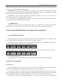
1. COMMUNICATION INTERFACE SPECIFICATION
The reader communicates with host (MCU MPU Controller) using serial communication interface RS232 or
RS485 and complete corresponding operation according to the host command. The communication parameter is
57600bps 1 start bit, 8 data bits, 1 stop bit without parity check bit. In the process of serial communication, the
least significant bit of one byte is transmitted first and the least significant byte of command data sequence is
transmitted first.
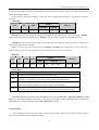
2. PROTOCOL DESCRIPTION
A communication procedure is sponsored by the host sending commands and data to the reader and the
reader returns the result status and data to host after command execution.
Reader receives a command executes a command, only the reader complete the implementation of a
command, to receive the next command. During the implementation of the command in the reader, if sending
commands to the reader, the command will be lost.
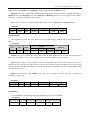
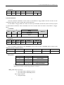
The following table shows the process of the host computer command:
HOST
DIRECTION
Command Data Block
→
READER
The interval between two consecutive bytes in the command data block should be less than 15ms. During
command data block sending, synchronization will lost if the host receives any data from the reader and the host
should stop command sending and restart the communication after 15ms.
The reader completes command execution in inventory ScanTime (not including host sending data time)
except inventory command after receiving host command and returns the results. During the period, it doesn’t
process any host data. The feedback of command execution results is as follows:
READER
DIRECTION
Command Data Block
→
HOST
The interval between two consecutive bytes in the response data block should be less than 15ms.
4
A11861 UHF RFID Reader User's Manual V2.0
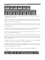
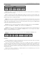
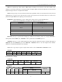
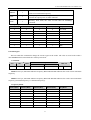
3. DATA BLOCK FORMAT
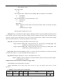
3.1 COMMAND DATA BLOCK
Len
Adr
Cmd
Data[]
LSB-CRC16
MSB-CRC16
COMMENT
LENGTH(Byte) COMMENT
Len
1
Command data block length 1 byte (not including itself). Value
range is 4~96. The number of Len equals the length of Data []
plus 4.
Adr
1
Reader address, 1 byte. Value range is 0~254. Only will the
reader conforming to the address response the command data
block. Value 255 is broadcasting address. All the readers will
response to the command data block with a broadcasting
address. The default value shall be zero.
Cmd
1
Operation command symbol, 1 byte.
Data[]
Variable
Operation command parameters. There is no parameter if the
LEN item equals 4.
LSB-CRC16
1
CRC-16 LSB. CRC-16 checksum, 2 bytes with least
significant byte first.
MSB-CRC16
1
CRC-16 MSB.
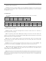
3.2 RESPONSE DATA BLOCK
Len
Adr
reCmd
Status
Data[]
LSB-CRC16
MSB-CRC16
COMMENT
LENGTH(Byte) COMMENT
Len
1
Response data block length 1 byte (not including itself). The
number of Len equals the length of Data [] plus 5.
Adr
1
Reader address, 1 byte. Value rang is 0~254.
reCmd
1
Response command symbol, 1 byte. If the command is
unrecognized, the reCmd is 0x00.
Status
1
Result status value, 1byte. Refer to following table for details.
Data[]
Variable
Response data. There is no this item if Len equals 5.
LSB-CRC16
1
CRC16 LSB .CRC-16 checksum, 2 bytes with least significant
byte first.
MSB-CRC16
1
CRC16 MSB
The default value of the reader address is 0x00. The host may change it by using reader-defined command
5
A11861 UHF RFID Reader User's Manual V2.0
“Write Adr”.
Cyclic Redundancy Check (CRC) computation includes all data from Len. A reference CRC computation
program is presented as follow:
C-Example:
#define PRESET_VALUE 0xFFFF
#define POLYNOMIAL 0x8408
unsigned int uiCrc16Cal(unsigned char const * pucY, unsigned char ucX)
{
unsigned char ucI,ucJ;
unsigned short int uiCrcValue = PRESET_VALUE;
for(ucI = 0; ucI < ucX; ucI++)
{
uiCrcValue = uiCrcValue ^ *(pucY + ucI);
for(ucJ = 0; ucJ < 8; ucJ++)
{
if(uiCrcValue & 0x0001)
{
uiCrcValue = (uiCrcValue >> 1) ^ POLYNOMIAL;
}
else
{
uiCrcValue = (uiCrcValue >> 1);
}
}
}
return uiCrcValue;
}
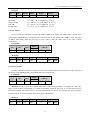
4. OPERATION COMMAND (CMD) SUMMARY
4.1 EPC C1 G2(
(ISO18000-6C)
)COMMAND
NUM
1
COMMAND
Inventory
CODE
COMMENT
0x01
The function is used to inventory tags in the effective field and
get their EPC values.
2
Read Data
0x02
The function is used to read part or all of a Tag’s Password,
EPC, TID, or User memory. To the word as a unit, start to read
data from the designated address.
3
Write Data
0x03
The function is used to write several words in a Tag’s
Reserved, EPC, TID, or User memory.
6
A11861 UHF RFID Reader User's Manual V2.0
4
Write EPC
0x04
The function is used to write EPC value in a Tag’s EPC
memory. Random write one tag in the effective field.
5
Kill Tag
0x05
The function is used to kill tag. After the tag killed, it never
process command.
6
Lock
0x06
The function is used to set Password area as readable and
writeable from any state, readable and writeable from the
secured state, permanently readable and writeable, never
readable and writeable. It used to set EPC, TID or User as
writeable from any state, writeable from the secured state,
permanently writeable, never writeable.
7
Block Erase
0x07
The function is used to erase multiple words in a Tag’s
Password, EPC, TID, or User memory.
0x08
The function is used to set designated tag read protection. After
the tag protected, it never process command. Even if inventory
tag, reader can not get the EPC number. The read protection
can be removed by executing Reset ReadProtect. Only NXP's
UCODE EPC G2X tags valid.
0x09
The function is used to random set one tag read protection in
the effective field. The tag must be having the same access
password. Only NXP's UCODE EPC G2X tags valid.
0x0a
The function is used to remove only one tag read protection in
the effective field. The tag must be having the same access
password. Only NXP's UCODE EPC G2X tags valid.
8
ReadProtect
9
Read Protect
(without EPC)
10
Reset ReadProtect
11
Check ReadProtect
0x0b
The function is used to check only one tag in the effective field,
whether the tag is protected. It can not check the tag whether
the tag support protection setting. Only NXP's UCODE EPC
G2X tags valid.
12
EAS Alarm
0x0c
The function is used to set or reset the EAS status bit of
designated tag. Only NXP's UCODE EPC G2X tags valid.
13
Check
EAS Alarm
0x0d
The function is used to check EAS status bit of any tag in the
effective field. Only NXP's UCODE EPC G2X tags valid.
14
Block Lock
0x0e
The function is used to permanently lock the designated data in
designated tag’s user memory. The locked data can be read
only, but not written and not erased. Only NXP's UCODE EPC
G2X tags valid.
15
Inventory(Single)
0x0f
The function is used to inventory one tag in the effective field
and get their EPC values.
16
Block Write
0x10
The function is used to write multiple words in a Tag’s
Reserved, EPC, TID, or User memory.
7
A11861 UHF RFID Reader User's Manual V2.0
4.2 18000-6B COMMAND
NUM
COMMAND
CODE
CONNECT
1
Inventory signal 6B
0x50
The function is used to Inventory only one tag in the effective
field and get their ID values. If more than one tag in the
effective field at the same time, reader may be get nothing.
2
Inventory multiple 6B
0x51
The function is used to according to the given conditions
Inventory tags in the effective field and get their ID values.
3
Read Data 6B
0x52
The function is used to start to read several bytes from the
designated address.
4
Write Data 6B
0x53
The function is used to start to write several bytes from the
designated address.
5
Check Lock 6B
0x54
The function is used to check whether the designated byte is
locked.
6
Lock 6B
0x55
The function is used to lock the designated byte.
4.3 READER DEFINED COMMAND
NUM
COMMAND
CODE
CONNECT
1
GetReader
Information
0x21
This function is used to get reader-related information such as
reader address (Adr), firmware version, supported protocol
type, Inventory ScanTime, power and frequency.
2
Set Region
0x22
Sets the current region. The function is used to set the reader
working of the lower limit and the upper limit of frequency.
0x24
This function is used to set a new address of the reader. The
address value will store in reader’s inner nonvolatile memory.
Default address value is 0x00. The value range is 0x00~0xFE.
The address 0xFF is reserved as the broadcasting address.
When user tries to write a 0xFF to Adr, the reader will set the
value to 0x00 automatically.
3
Set Address
4
Set ScanTime
0x25
This function is used to set a new value to Inventory ScanTime
of an appointed reader. The range is 3~255 corresponding to
3*100ms~255*100ms Inventory ScanTime. The default value
of Inventory ScanTime is 10*100ms.
5
Set Baud Rate
0x28
The function is used to change the serial port baud rate.
6
Set Power
0x2F
The function is used to set the power of reader.
7
Acousto-optic Control
0x33
Acousto-optic Control
8
Set Wiegand
0x34
The function is used to set Wiegand parameter.
9
Set WorkMode
0x35
The function is used to set work mode parameter.
10
Get WorkMode
0x36
The function is used to get work mode parameter.
11
SetEasAccuracy
0x37
The function is used to set EasAlarm Accuracy.
12
Syris Response Offset
0x38
The function is used to set Syris485 response offset time.
13
Trigger Offset
0x3b
The function is used to set Trigger Offset time.
8
A11861 UHF RFID Reader User's Manual V2.0
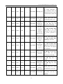
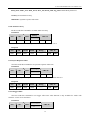
5. LIST OF COMMAND EXECUTION RESULT STATUS
RESPONSE DATA BLOCK
Len
Length
of
Data[]
+5
Length
of
Data[]
+5
Length
of
Data[]
+5
Length
of
Data[]
+5
Length
of
Data[]
+5
5
Adr
0xXX
0xXX
0xXX
0xXX
0xXX
0xXX
reCmd
0xXX
0x01
0x01
0x01
0x01
0xXX
Status
0x00
0x01
0x02
0x03
0x04
0x05
Data[]
……..
……..
……..
……..
……..
__
STATES
CONNECT
Success
Return status 0x00 to host
after command is executed
successfully. Data block
contains result data.
Return before
Inventory
finished
Return status 0x01 to host
when the reader executes
an Inventory command and
gets some complete G2
tags’
EPC
before
user-defined
Inventory-ScanTime
finished.
the
Inventory-sca
n-time
overflow
Return status 0x02 when
the reader executes an
Inventory command and
does not get all G2 tags’
EPC before user-defined
Inventory-ScanTime
overflows.
More Data
Return status 0x03 when
the reader executes an
Inventory command and
gets many G2 tags’ EPC,
Data can not be completed
within in a message, and
then send in multiple.
Reader
module flash
is Full
Return status 0x04 when
the reader executes an
Inventory command and
gets G2 tags’ EPC too
much, more than the
storage capacity of reader.
Access
Password
error
Return status 0x05 when
the reader implements a
command whit password,
while the password is
wrong.
CRC16
LSB+MSB
LSB+MSB
LSB+MSB
LSB+MSB
LSB+MSB
LSB+MSB
9
A11861 UHF RFID Reader User's Manual V2.0
5
5
5
5
5
5
5
5
5
5
5
0xXX
0xXX
0xXX
0xXX
0xXX
0xXX
0xXX
0xXX
0xXX
0xXX
0xXX
0x05
0x05
0xXX
0xXX
0x0a
0x0a
0x53
0x55
0x55
0xXX
0xXX
0x09
0x0a
0x0b
0x0c
0x0d
0x0e
0x10
0x11
0x12
0x13
0x14
__
__
__
__
__
__
__
__
__
__
__
LSB+MSB
Kill Tag error
Return status 0x09 when
the reader implement a
Kill command, while the
kill password error, or poor
communication reader and
tag.
LSB+MSB
Kill Password
error can’t be
zero
Return status 0x0a when
the Kill Password is zero.
LSB+MSB
Tag Not
Support the
command
Return status 0x0b when
the G2 Tag dose not
supports the command.
LSB+MSB
Use the
command,
Access
Password
Can’t be Zero
Return status 0x0c when
the NXP UCODE EPC
G2X Tag is set read
protection or EAS Alarm,
the access password is
zero.
LSB+MSB
Tag is
protected,
cannot set it
again
Return status 0x0d when
the NXP UCODE EPC
G2X Tag is protected.
LSB+MSB
Tag is
unprotected,
no need to
reset it
Return status 0x0e when
the NXP UCODE EPC
G2X Tag is unprotected or
the tag does not support
the command.
LSB+MSB
There is some
locked bytes,
write fail
Return status 0x10 when
the 6B Tag is written data,
while there are some
locked bytes, write fail.
LSB+MSB
can not lock it
Return status 0x11 when
the 6B Tag can’t be
locked.
LSB+MSB
Be locked,
cannot lock it
again
Return status 0x12 when
the 6B Tag has been
locked.
LSB+MSB
Save Fail,
Can Use
Before Power
Return status 0x13 when
the parameter is save fail.
Cannot adjust
Return status 0x14 when
the power can not be
adjusted.
LSB+MSB
10
A11861 UHF RFID Reader User's Manual V2.0
Length
of
Data[]
+5
Length
of
Data[]
+5
Length
of
Data[]
+5
Length
of
Data[]
+5
0xXX
0xXX
0xXX
0xXX
0x51
0x51
0x51
0x51
0X15
0x16
0x17
0x18
……..
……..
……..
……..
LSB+MSB
LSB+MSB
LSB+MSB
LSB+MSB
Return before
Inventory
finished
Return status 0x15 to host
when the reader executes
an Inventory command and
gets some complete 6B
tags’
UID
before
user-defined
Inventory-ScanTime
finished.
Inventory-Sca
n-Time
overflow
Return status 0x16 when
the reader executes an
Inventory command and
does not get all 6B tags’
UID before user-defined
Inventory-ScanTime
overflows.
More Data
Return status 0x17 when
the reader executes an
Inventory command and
gets many 6B tags’ UID,
Data can not be completed
within in a message, and
then send in multiple.
Reader
module flash
is Full
Return status 0x18 when
the reader executes an
Inventory command and
gets 6B tags’ UID too
much, more than the
storage capacity of reader.
Return status 0x19 when
the tag can’t set EAS
Alarm. There may be the
tag does not support the
command, or the tag’s
access password be zero.
5
0xXX
0xXX
0x19
__
LSB+MSB
Not Support
Command Or
Access
Password
5
0xXX
0xXX
0xF9
__
LSB+MSB
Command
execute error
Return status 0xF9 when
Command execute error
LSB+MSB
Get Tag, Poor
Communicati
on, Inoperable
Return status 0xFA when
there are some tags in the
effective field, but Poor
Communication between
reader and tag.
LSB+MSB
No Tag
Operable
Return status 0xFB when
there is no tag in the
effective field.
5
5
0xXX
0xXX
0xXX
0xXX
0xFA
0xFB
__
__
11
A11861 UHF RFID Reader User's Manual V2.0
6
5
5
5
0xXX
0xXX
0xXX
0xXX
0xXX
0xXX
0x00
0xXX
Err_cod
e
0xFC
0xFD
__
0xFE
__
0xFF
__
Tag Return
Error Code
Return status 0xFC when
the tag returns Error Code.
Command
length wrong
Return status 0xFD when
the length of command
operands doesn’t conform
to the command request.
LSB+MSB
Illegal
command
Return status 0xFE when
the command is an
unrecognized command or
CRC error.
LSB+MSB
Parameter
Error
Return status 0xFF when
the command parameter
is invalid.
LSB+MSB
LSB+MSB
6. TAG ERROR CODES
EPC C1G2
ISO18000-6C
Error-Code Support
Tag error codes
Error-Code
Error-Code Name
Other error
Catch-all for errors not covered by other
codes.
Memory overrun
The specified memory location does not
exist or the EPC length field is not
supported by the Tag.
0x04
Memory locked
The specified memory location is locked
and/or perm locked and is either not
writeable or not readable.
0x0b
Insufficient power
The Tag has insufficient power to
perform the memory-write operation
0x0f
Non-specific error
The Tag does not support error-specific
codes
0x00
0x03
Error-specific
Non-specific
Error Description
7. TAG MEMORY AND ISSUES REQUIRING ATTENTION
A. EPC C1G2 TAG
G2 TAG
Tag memory shall be logically separated into four distinct banks, each of which may comprise zero or more
memory words. The four storage areas:
Reserved memory (password memory) shall contain the kill and and/or access passwords, if passwords are
implemented on the Tag. The kill password shall be stored at memory addresses 00h to 1Fh; the access password
shall be stored at memory addresses 20h to 3Fh.
EPC memory shall contain a Stored CRC at memory addresses 00h to 0Fh, a Stored PC at addresses 10h to
1Fh, a code (such as an EPC, and hereafter referred to as an EPC) that identifies the object to which the Tag is or
12
A11861 UHF RFID Reader User's Manual V2.0
will be attached beginning at address 20h, and if the Tag implements Extended Protocol Control (XPC) then either
one or two XPC word(s) beginning at address 210h.
TID memory shall contain an 8-bit ISO/IEC 15963 allocation class identifier at memory locations 00h to
07h. TID memory shall contain sufficient identifying information above 07h for an Interrogator to uniquely
identify the custom commands and/or optional features that a Tag supports.
User memory is optional. This area of different manufacturers is different. There is no user area in G2 tag of
Inpinj Company. There are 28 words in Philips Company.
Can write protect in four distinct banks. It means this memory is never writeable or not writeable under the
non-safe state; only password area can set unreadable.
B. 18000-6B TAG
6B tag has a memory space, the minimum 8 bytes (byte 0- 7) is UID of the tag, and can't be rewritten.
Following byte all can be rewritten, can be locked too, but once locking, can't rewrite and unblock again.
8. DETAILED DESCRIPTION OF OPERATION COMMAND
8.1 COMMAND OVERVIEV
The reader supports three kinds of command, one kind is the ISO/IEC 18000-6 protocol command, another
kind is reader-defined command, and also one kind is the transparent command.
If the host input of the command is an unrecognized command, such as the command does not support, or
CRC error in the command, then the return value is as follows:
Len
Adr
reCmd
Status
0x05
0xXX
0x00
0xFE
CRC-16
LSB
MSB
If the length of command operands doesn’t conform to the command request, the return value is as follows:
Len
Adr
reCmd
Status
0x05
0xXX
0xXX
0xFD
CRC-16
LSB
MSB
Two kinds of command reader cannot respond:
1. The reader’s address error.
2. The command is incomplete, namely the command Len is longer than the actual command length.
8.2 EPC C1G2 COMMAND
8.2.1 Inventory
The command function is used to inventory tags in the effective field and get their EPC or TID values. The
reader executes an Inventory command and gets tag’s EPC before any other operation.
The user may accord need to establish this command the first biggest running time (Inventory scan time),
before the command enquires. The reader completes command execution in inventory ScanTime (not including
host sending data time) except inventory command after receiving host command and returns the results.
The default value is 0x0A (corresponding to 10*100ms=1s). The value range is 0x03~0xFF (corresponding to
13
A11861 UHF RFID Reader User's Manual V2.0
3*100ms~255*100ms). In various environments, the actual inventory scan time may be 0~75ms longer than the
InventoryScanTime defined.
If the inventory scan time establishes excessively short, possibly will inventory no tag appear in inventory
scan time.
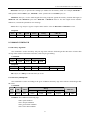
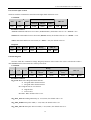
Command:
Len
Adr
0xXX
0xXX
Data[]
Cmd
0x01
CRC-16
AdrTID
LenTID
0xXX
0xXX
LSB
MSB
Parameter Connect:
AdrTID: One byte. It specifies the starting word address for the TID memory read. For example, AdrTID =
00h specifies the first 16-bit memory word, AdrTID = 01h specifies the second 16-bit memory word, etc.
LenTID: One byte. It specifies the number of 16-bit words to be read. The value is less then 16, otherwise, it
returns the parameters error message.
Notes: It will get tags’ EPC values when the AdrTID and LenTID vacant. Otherwise, get tags’ TID values.
TID-inventory function is only available for reader with firmware version V2.36 and above.
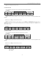
Respond:
Data[]
Len
0xXX
Adr
0xXX
reCmd
0x01
Status
0xXX
CRC-16
Num
EPC ID
0xXX
EPC-1, EPC-2, EPC-3…
LSB
MSB
Parameter Connect:
Status Table:
Status
Connect
0x01
Command over, and return inventoried tag’s EPC (TID).
0x02
The reader does not get all G2 tags’ EPC/TID before user-defined Inventory-ScanTime
overflows. Command force quit, and returns inventoried tags’ EPC (TID).
0x03
The reader executes an Inventory command and gets many G2 tags’ EPC (TID). Data
can not be completed within in a message, and then send in multiple.
0x04
The reader executes an Inventory command and gets G2 tags’ EPC (TID) too much,
more than the storage capacity of reader, and returns inventoried tags’ EPC (TID).
Num: The number of tag detected.
EPC ID: Inventoried tag’s EPC (TID) data, EPC-1 is the first tag EPC Len + EPC Data (TID Len + TID
Data), etc. The most significant word (EPC C1 G2 data in word units) of EPC is transmitted first and the most
significant byte of word is transmitted first. EPC (TID) Len is one byte.
8.2.2 Read Data
The command is used to read part or all of a Tag’s Password, EPC, TID, or User memory. To the word as a
unit, start to read data from the designated address.
14
A11861 UHF RFID Reader User's Manual V2.0
Command:
Len
Adr
Cmd
Data[]
0xXX
0xXX
0x02
——
CRC-16
LSB
MSB
Data as follows:
Data[]
ENum
EPC
Mem
WordPtr
Num
Pwd
MaskAdr
MaskLen
0xXX
Variable
0xXX
0xXX
0xXX
4Byte
0xXX
0xXX
Parameter Connect:
ENum: EPC length in word units. The length of EPC is less than 15 words, can be 0 or 15. Otherwise, it
returns the parameters error message.
EPC: Be operated tag’s EPC number. EPC length according to the decision of the EPC number, EPC
numbers in word units, and must be an integer number of lengths. High word first, the high byte of each word first.
Requirement given here is a complete EPC number.
Mem: One byte. It specifies whether the Read accesses Password, EPC, TID, or User memory. 0x00:
Password memory; 0x01: EPC memory; 0x02; TID memory; 0x03: User memory. Other values reserved. Other
value when error occurred.
WordPtr: One byte. It specifies the starting word address for the memory read. For example, WordPtr = 00h
specifies the first 16-bit memory word, WordPtr = 01h specifies the second 16-bit memory word, etc.
Num: One byte. It specifies the number of 16-bit words to be read. The value is less then 120, can not be 0.
Otherwise, it returns the parameters error message.
Pwd: Four bytes, they are Access Password. The most significant word of Access Password is first, the most
significant byte of word is first. The first bit of 32-bit access password is left, and the last bit of 32-bit access
password is right. Only done the memory set to lock and the Tag’s Access Password is not zero, it needs right Pwd.
In other cases, Pwd can be zero.
MaskAdr: One byte, it specifies the starting byte address for the memory mask. For example, MaskAdr =
0x00 specifies the first EPC bytes, MaskAdr = 0x01 specifies the second EPC bytes, etc.
MaskLen: One byte, it is the mask length. That a Tag compares against the memory location that begins at
MaskAdr and ends MaskLen bytes later. MaskAdr + MaskLen must be less the length of ECP number.
Otherwise, it returns the parameters error message.
Notes: That a tag compares against complete EPC number when the MaskAdr and MaskLen vacant.
Respond:
Len
Adr
reCmd
Status
Data[]
0xXX
0xXX
0x02
0x00
Word1 Word2,…
15
CRC-16
LSB
MSB
A11861 UHF RFID Reader User's Manual V2.0
Parameter Connect:
Word1, Word2….: In word units, one word is two bytes. High byte is first. Word1 is the word which
reads from the start address, Word2 is the word which reads from the second address, etc.
8.2.3 Write Data
The command is used to write several words in a Tag’s Reserved, EPC, TID, or User memory.
Command:
Len
Adr
Cmd
Data[]
0xXX
0xXX
0x03
——
CRC-16
LSB
MSB
Data as follows:
Data[]
WNum
ENum
EPC
Mem
WordPtr
Wdt
Pwd
MaskAdr
MaskLen
0xXX
0xXX
Variable
0xXX
0xXX
Variable
4Byte
0xXX
0xXX
Parameter Connect:
WNum: One byte. It specifies the number of 16-bit words to be written. The value can not be 0. Otherwise, it
returns the parameters error message.
ENum: EPC length in word units. The length of EPC is less than 15 words, can be 0 or 15. Otherwise, it
returns the parameters error message.
EPC: Be operated tag’s EPC number. EPC length according to the decision of the EPC number, EPC
numbers in word units, and must be an integer number of lengths. High word first, the high byte of each word first.
Requirement given here is a complete EPC number.
Mem: One byte. It specifies whether the Write accesses Password, EPC, TID, or User memory. 0x00:
Password memory; 0x01: EPC memory; 0x02; TID memory; 0x03: User memory. Other values reserved. Other
value when error occurred.
WordPtr: One byte. It specifies the starting word address for the memory write. For example, WordPtr = 00h
specifies the first 16-bit memory word, WordPtr = 01h specifies the second 16-bit memory word, etc.
Wdt: Be written words. The most significant byte of each word is first. Wdt specifies the array of the word
to be written. For example, WordPtr equal 0x02, then the first word in Data write in the address 0x02 of
designated Mem, the second word write in 0x03, etc.
Pwd: Four bytes, they are Access Password. The most significant word of Access Password is first, the most
significant byte of word is first. The first bit of 32-bit access password is left, and the last bit of 32-bit access
password is right. Only done the memory set to lock and the Access Password is not zero, it needs Pwd. In other
cases, Pwd can be zero.
MaskAdr: One byte, it specifies the starting byte address for the memory mask. For example, MaskAdr =
16
A11861 UHF RFID Reader User's Manual V2.0
0x00 specifies the first EPC bytes, MaskAdr = 0x01 specifies the second EPC bytes, etc.
MaskLen: One byte, it is the mask length. That a Tag compares against the memory location that begins at
MaskAdr and ends MaskLen bytes later. MaskAdr + MaskLen must be less the length of ECP number.
Otherwise, it returns the parameters error message.
Notes: That a tag compares against complete EPC number when the MaskAdr and MaskLen vacant.
Respond:
Len
Adr
reCmd
Status
Data[]
0x05
0xXX
0x03
0x00
——
CRC-16
LSB
MSB
8.2.4 Write EPC
The command is used to write EPC number in a Tag’s EPC memory. Random write one tag in the effective
field.
Command:
Len
Adr
Cmd
0xXX
0xXX
0x04
Data[]
ENum
Pwd
WEPC
0xXX
4Byte
Variable
CRC-16
LSB
MSB
Parameter Connect:
ENum: One byte, it specifies the array of the word to be written EPC length in word units. The length of
EPC is not more than 15 words, can’t be 0. Otherwise, it returns the parameters error message.
Pwd: Four bytes, they are Access Password. The most significant word of Access Password is first, the most
significant byte of word is first. The first bit of 32-bit access password is left, and the last bit of 32-bit access
password is right. Only done the memory set to lock and the Access Password is not zero, it needs Pwd. In other
cases, Pwd can be zero.
WEPC: Be written EPC value. WEPC is not more than 15 words, can’t be 0. Otherwise, it returns the
parameters error message.
Respond:
Len
Adr
reCmd
Status
Data[]
0x05
0xXX
0x04
0x00
——
CRC-16
LSB
MSB
8.2.5 Kill Tag
The command is used to kill tag. After the tag killed, it never process command.
Command:
Len
Adr
Cmd
Data[]
0xXX
0xXX
0x05
——
CRC-16
LSB
17
MSB
A11861 UHF RFID Reader User's Manual V2.0
Data as follows:
Data[]
ENum
EPC
Killpwd
MaskAdr
MaskLen
0xXX
Variable
4Byte
0xXX
0xXX
Parameter Connect:
ENum: EPC length in word units. The length of EPC is less than 15 words, can be 0 or 15. Otherwise, it
returns the parameters error message.
EPC: Be operated tag’s EPC number. EPC length according to the decision of the EPC number, EPC
numbers in word units, and must be an integer number of lengths. High word first, the high byte of each word first.
Requirement given here is a complete EPC number.
Killpwd: Four bytes, they are Kill Password. The most significant word of Kill Password is first, the most
significant byte of word is first. The first bit of 32-bit Kill Password is left, and the last bit of 32-bit Kill Password
is right. Tag’s whose Kill Password is zero do not execute a kill operation; if such a Tag receives a Kill command
it ignores the command and backscatters an error code
MaskAdr: One byte, it specifies the starting byte address for the memory mask. For example, MaskAdr =
0x00 specifies the first EPC bytes, MaskAdr = 0x01 specifies the second EPC bytes, etc.
MaskLen: One byte, it is the mask length. That a Tag compares against the memory location that begins at
MaskAdr and ends MaskLen bytes later. MaskAdr + MaskLen must be less the length of ECP number.
Otherwise, it returns the parameters error message.
Notes: That a tag compares against complete EPC number when the MaskAdr and MaskLen vacant.
Respond:
Len
Adr
reCmd
Status
Data[]
0x05
0xXX
0x05
0x00
——
CRC-16
LSB
MSB
8.2.6 Lock
The Lock command Lock reversibly or permanently locks a password or an entire EPC, TID, or User memory
bank in a readable/writeable or unreadable/unwriteable state.
Once tag’s password memory establishes to forever may be readable and writable or unreadable and
unwriteable, then later cannot change its read-write protection again. Tag’s EPC memory, TID memory or user
memory, if establishes to forever may be writeable or unwriteable, then later cannot change its read-write
protection again. If sends the command to want forcefully to change the above several states, then the tag will
return to the error code.
When the tag’s memory established in a readable/writeable state, the command must give the Access
Password, so tag’s Access Password is not zero.
18
A11861 UHF RFID Reader User's Manual V2.0
Command:
Len
Adr
Cmd
Data[]
0xXX
0xXX
0x06
——
CRC-16
LSB
MSB
Data as follows:
Data[]
ENum
0xXX
EPC
Select
SetProtect
Pwd
MaskAdr
MaskLen
Variable
0xXX
0xXX
4Byte
0xXX
0xXX
Parameter Connect:
ENum: EPC length in word units. The length of EPC is less than 15 words, can be 0 or 15. Otherwise, it
returns the parameters error message.
EPC: Be operated tag’s EPC number. EPC length according to the decision of the EPC number, EPC
numbers in word units, and must be an integer number of lengths. High word first, the high byte of each word first.
Requirement given here is a complete EPC number.
Select: One byte, defined as follows:
0x00: Control Kill Password protection setting.
0x01: Control Access password protection setting.
0x02: Control EPC memory protection setting.
0x03: Control TID memory protection setting.
0x04: Control User memory protection setting.
Other value when error occurred.
SetProtect:
When Select is 0x00 or 0x01, SetProtect means as follows:
0x00: readable and writeable from any state.
0x01: permanently readable and writeable.
0x02: readable and writeable from the secured state.
0x03: never readable and writeable
When Select is 0x02, 0x03 or 0x04, SetProtect means as follows:
0x00: writeable from any state.
0x01: permanently writeable.
0x02: writeable from the secured state.
0x03: never writeable.
Other value when error occurred.
Pwd: Four bytes, they are Access Password. The most significant word of Access Password is first, the most
significant byte of word is first. The first bit of 32-bit access password is left, and the last bit of 32-bit access
password is right. Pwd must be right Access Password.
MaskAdr: One byte, it specifies the starting byte address for the memory mask. For example, MaskAdr =
0x00 specifies the first EPC bytes, MaskAdr = 0x01 specifies the second EPC bytes, etc.
19
A11861 UHF RFID Reader User's Manual V2.0
MaskLen: One byte, it is the mask length. That a Tag compares against the memory location that begins at
MaskAdr and ends MaskLen bytes later. MaskAdr + MaskLen must be less the length of ECP number.
Otherwise, it returns the parameters error message.
Notes: That a tag compares against complete EPC number when the MaskAdr and MaskLen vacant.
Respond:
Len
Adr
reCmd
Status
Data[]
0x05
0xXX
0x06
0x00
——
CRC-16
LSB
MSB
8.2.7 BlockErase
The command is used to erase multiple words in a Tag’s Password, EPC, TID, or User memory.
Command:
Len
Adr
Cmd
Data[]
0xXX
0xXX
0x07
——
CRC-16
LSB
MSB
Data as follows:
Data[]
ENum
EPC
Mem
WordPtr
Num
Pwd
MaskAdr
MaskLen
0xXX
Variable
0xXX
0xXX
0xXX
4Byte
0xXX
0xXX
Parameter Connect:
ENum: EPC length in word units. The length of EPC is less than 15 words, can be 0 or 15. Otherwise, it
returns the parameters error message.
EPC: Be operated tag’s EPC number. EPC length according to the decision of the EPC number, EPC
numbers in word units, and must be an integer number of lengths. High word first, the high byte of each word first.
Requirement given here is a complete EPC number.
Mem: One byte. It specifies whether the Erase accesses Password, EPC, TID, or User memory. 0x00:
Password memory; 0x01: EPC memory; 0x02; TID memory; 0x03: User memory. Other values reserved. Other
value when error occurred.
WordPtr: One byte. It specifies the starting word address for the memory block erase. For example, WordPtr
= 00h specifies the first 16-bit memory word, WordPtr = 01h specifies the second 16-bit memory word, etc.
WordPtr must be bigger than 0x00 when it erases EPC memory.
Num: One byte. It specifies the number of 16-bit words to be erased. If Num = 0x00, it returns the
parameters error message.
Pwd: Four bytes, they are Access Password. The most significant word of Access Password is first, the most
significant byte of word is first. The first bit of 32-bit access password is left, and the last bit of 32-bit access
password is right. Only done the memory set to lock and the Access Password is not zero, it needs Pwd. In other
cases, Pwd can be zero.
20
A11861 UHF RFID Reader User's Manual V2.0
MaskAdr: One byte, it specifies the starting byte address for the memory mask. For example, MaskAdr =
0x00 specifies the first EPC bytes, MaskAdr = 0x01 specifies the second EPC bytes, etc.
MaskLen: One byte, it is the mask length. That a Tag compares against the memory location that begins at
MaskAdr and ends MaskLen bytes later. MaskAdr + MaskLen must be less the length of ECP number.
Otherwise, it returns the parameters error message.
Notes: That a tag compares against complete EPC number when the MaskAdr and MaskLen vacant.
Respond:
Len
Adr
reCmd
Status
Data[]
0x05
0xXX
0x07
0x00
——
CRC-16
LSB
MSB
8.2.8 ReadProtect (With EPC)
The command is used to set designated tag read protection. After the tag protected, it never process command.
Even if inventory tag, reader can not get the EPC number. The read protection can be removed by executing Reset
ReadProtect. Only NXP's UCODE EPC G2X tags valid.
Command:
Len
Adr
Cmd
Data[]
0xXX
0xXX
0x08
——
CRC-16
LSB
MSB
Data as follows:
Data[]
ENum
EPC
Pwd
MaskAdr
MaskLen
0xXX
Variable
4Byte
0xXX
0xXX
Parameter Connect:
ENum: EPC length in word units. The length of EPC is less than 15 words, can be 0 or 15. Otherwise, it
returns the parameters error message.
EPC: Be operated tag’s EPC number. EPC length according to the decision of the EPC number, EPC
numbers in word units, and must be an integer number of lengths. High word first, the high byte of each word first.
Requirement given here is a complete EPC number.
Pwd: Four bytes, they are Access Password. The most significant word of Access Password is first, the most
significant byte of word is first. The first bit of 32-bit access password is left, and the last bit of 32-bit access
password is right. Tags’ Access Password can not be zero.
MaskAdr: One byte, it specifies the starting byte address for the memory mask. For example, MaskAdr =
0x00 specifies the first EPC bytes, MaskAdr = 0x01 specifies the second EPC bytes, etc.
MaskLen: One byte, it is the mask length. That a Tag compares against the memory location that begins at
21
A11861 UHF RFID Reader User's Manual V2.0
MaskAdr and ends MaskLen bytes later. MaskAdr + MaskLen must be less the length of ECP number.
Otherwise, it returns the parameters error message.
Notes: That a tag compares against complete EPC number when the MaskAdr and MaskLen vacant.
Respond:
Len
Adr
reCmd
Status
Data[]
0x05
0xXX
0x08
0x00
——
CRC-16
LSB
MSB
8.2.9 ReadProtect (Without EPC)
The command is used to random set random one tag read protection in the effective field. The tag must be
having the same access password. Only NXP's UCODE EPC G2X tags valid.
Command:
Len
Adr
Cmd
0x08
0xXX
0x09
Data[]
Pwd
4Byte
CRC-16
LSB
MSB
Parameter Connect:
Pwd: Four bytes, they are Access Password. The most significant word of Access Password is first, the most
significant byte of word is first. The first bit of 32-bit access password is left, and the last bit of 32-bit access
password is right. Tags’ Access Password can not be zero.
Respond:
Len
Adr
reCmd
Status
Data[]
0x05
0xXX
0x09
0x00
——
CRC-16
LSB
MSB
8.2.10 Reset ReadProtect
The command is used to remove only one tag read protection in the effective field. The tag must be having
the same access password. Only NXP's UCODE EPC G2X tags valid.
Command:
Len
Adr
Cmd
0x08
0xXX
0x0a
Data[]
Pwd
4Byte
CRC-16
LSB
MSB
Parameter Connect:
Pwd: Four bytes, they are Access Password. The most significant word of Access Password is first, the most
significant byte of word is first. The first bit of 32-bit access password is left, and the last bit of 32-bit access
password is right. Pwd must be right tag’s Access Password.
Respond:
Len
Adr
reCmd
Status
Data[]
0x05
0xXX
0x0a
0x00
——
CRC-16
LSB
Notes: If a tag does not support the command, is unlocked.
22
MSB
A11861 UHF RFID Reader User's Manual V2.0
8.2.11 Check ReadProtect
The command is used to check only one tag in the effective field, whether the tag is protected. It can not
check the tag whether the tag support protection setting. Only NXP's UCODE EPC G2X tags valid.
Command:
Len
Adr
Cmd
Data[]
0x04
0xXX
0x0b
——
CRC-16
LSB
MSB
Respond:
Len
Adr
reCmd
Status
Data[]
0x06
0xXX
0x0b
0x00
ReadPro
CRC-16
LSB
MSB
Parameter Connect:
ReadPro
Connect
0x00
Tag is protected.
0x01
Tag is unprotected.
Notes: If a tag does not support the command, is unprotected.
8.2.12 EAS Alarm
The function is used to set or reset the EAS status bit of designated tag. Only NXP's UCODE EPC G2X tags
valid.
Command:
Len
Adr
Cmd
Data[]
0xXX
0xXX
0x0c
——
CRC-16
LSB
MSB
Data as follows:
Data[]
ENum
EPC
Pwd
EAS
MaskAdr
MaskLen
0xXX
Variable
4Byte
0xXX
0xXX
0xXX
Parameter Connect:
ENum: EPC length in word units. The length of EPC is less than 15 words, can be 0 or 15. Otherwise, it
returns the parameters error message.
EPC: Be operated tag’s EPC number. EPC length according to the decision of the EPC number, EPC
numbers in word units, and must be an integer number of lengths. High word first, the high byte of each word first.
Requirement given here is a complete EPC number.
Pwd: Four bytes, they are Access Password. The most significant word of Access Password is first, the most
significant byte of word is first. The first bit of 32-bit access password is left, and the last bit of 32-bit access
password is right. Tags’ Access Password can not be zero.
EAS: One byte. Bit0=0 means reset the EAS state, Bit0=1 means set the EAS state.Bit1~Bit7 default 0.
23
A11861 UHF RFID Reader User's Manual V2.0
MaskAdr: One byte, it specifies the starting byte address for the memory mask. For example, MaskAdr =
0x00 specifies the first EPC bytes, MaskAdr = 0x01 specifies the second EPC bytes, etc.
MaskLen: One byte, it is the mask length. That a Tag compares against the memory location that begins at
MaskAdr and ends MaskLen bytes later. MaskAdr + MaskLen must be less the length of ECP number.
Otherwise, it returns the parameters error message.
Notes: That a tag compares against complete EPC number when the MaskAdr and MaskLen vacant.
Respond:
Len
Adr
reCmd
Status
Data[]
0x05
0xXX
0x0c
0x00
——
CRC-16
LSB
MSB
8.2.13 Check EAS Alarm
The function is used to check EAS status bit of any tag in the effective field. Only NXP's UCODE EPC G2X
tags valid.
Command:
Len
Adr
Cmd
Data[]
0x04
0xXX
0x0d
——
CRC-16
LSB
MSB
Respond:
Len
Adr
reCmd
Status
Data[]
0x05
0xXX
0x0d
0x00
——
CRC-16
LSB
MSB
It returns "no tag actionable" message when No EAS alarm
8.2.14 User Block Lock
The command is used to permanently lock the designated data in designated tag’s user memory. Block Lock
command supports an additional locking mechanism, which allows the locking of individual 32 bit blocks (rows)
in the 224 bit User Memory. Once locked these locks cannot be unlocked. Only NXP's UCODE EPC G2X tags
valid.
Command:
Len
Adr
Cmd
Data[]
0xXX
0xXX
0x0e
——
CRC-16
LSB
MSB
Data as follows:
Data[]
ENum
EPC
pwd
WrdPointer
MaskAdr
MaskLen
0xXX
Variable
4Byte
0xXX
0xXX
0xXX
Parameter Connect:
ENum: EPC length in word units. The length of EPC is less than 15 words, can be 0 or 15. Otherwise, it
returns the parameters error message.
24
A11861 UHF RFID Reader User's Manual V2.0
EPC: Be operated tag’s EPC number. EPC length according to the decision of the EPC number, EPC
numbers in word units, and must be an integer number of lengths. High word first, the high byte of each word first.
Requirement given here is a complete EPC number.
Pwd: Four bytes, they are Access Password. The most significant word of Access Password is first, the most
significant byte of word is first. The first bit of 32-bit access password is left, and the last bit of 32-bit access
password is right. Pwd must be right tag’s Access Password.
WrdPointer: Each EEPROM row can be addressed by either of the two related WordPointers:
Either of two WordPointers can address one single User Memory row
WrdPointer
User EEPROM row
0 or 1
0
2 or 3
1
4 or 5
2
6 or 7
3
8 or 9
4
10 or 11
5
12 or 13
6
MaskAdr: One byte, it specifies the starting byte address for the memory mask. For example, MaskAdr =
0x00 specifies the first EPC bytes, MaskAdr = 0x01 specifies the second EPC bytes, etc.
MaskLen: One byte, it is the mask length. That a Tag compares against the memory location that begins at
MaskAdr and ends MaskLen bytes later. MaskAdr + MaskLen must be less the length of ECP number.
Otherwise, it returns the parameters error message.
Notes: That a tag compares against complete EPC number when the MaskAdr and MaskLen vacant.
Respond:
Len
Adr
reCmd
Status
Data[]
0x05
0xXX
0x0e
0x00
——
CRC-16
LSB
MSB
8.2.15 Inventory (Single)
Command:
Len
Adr
Cmd
Data[]
0x04
0xXX
0x0f
——
CRC-16
LSB
MSB
Respond:
Data[]
Len
0xXX
Adr
0xXX
reCmd
0x0f
Status
0x01
CRC-16
Num
EPC ID
0x01
EPC-1
25
LSB
MSB
A11861 UHF RFID Reader User's Manual V2.0
Num: The number of tag detected.
EPC ID: Inventoried tag’s EPC data, EPC-1 is the first tag EPC Len + EPC data. The most significant word
(EPC C1 G2 data in word units) of EPC is transmitted first and the most significant byte of word is transmitted
first. EPC Len is one byte.
8.2.16 Block Write
The command is used to write multiple words in a Tag’s Reserved, EPC, TID, or User memory.
Command:
Len
Adr
Cmd
Data[]
0xXX
0xXX
0x10
——
CRC-16
LSB
MSB
Data as follows:
Data[]
WNum
ENum
EPC
Mem
WordPtr
Wdt
Pwd
MaskAdr
MaskLen
0xXX
0xXX
Variable
0xXX
0xXX
Variable
4Byte
0xXX
0xXX
Parameter Connect:
WNum: One byte. It specifies the number of 16-bit words to be written. The value can not be 0. Otherwise, it
returns the parameters error message.
ENum: EPC length in word units. The length of EPC is less than 15 words, can be 0 or 15. Otherwise, it
returns the parameters error message.
EPC: Be operated tag’s EPC number. EPC length according to the decision of the EPC number, EPC
numbers in word units, and must be an integer number of lengths. High word first, the high byte of each word first.
Requirement given here is a complete EPC number.
Mem: One byte. It specifies whether the Write accesses Password, EPC, TID, or User memory. 0x00:
Password memory; 0x01: EPC memory; 0x02; TID memory; 0x03: User memory. Other values reserved. Other
value when error occurred.
WordPtr: One byte. It specifies the starting word address for the memory write. For example, WordPtr = 00h
specifies the first 16-bit memory word, WordPtr = 01h specifies the second 16-bit memory word, etc.
Wdt: Be written words. The most significant byte of each word is first. Wdt specifies the array of the word
to be written. For example, WordPtr equal 0x02, then the first word in Data write in the address 0x02 of
designated Mem, the second word write in 0x03, etc.
Pwd: Four bytes, they are Access Password. The most significant word of Access Password is first, the most
significant byte of word is first. The first bit of 32-bit access password is left, and the last bit of 32-bit access
password is right. Only done the memory set to lock and the Access Password is not zero, it needs Pwd. In other
cases, Pwd can be zero.
26
A11861 UHF RFID Reader User's Manual V2.0
MaskAdr: One byte, it specifies the starting byte address for the memory mask. For example, MaskAdr =
0x00 specifies the first EPC bytes, MaskAdr = 0x01 specifies the second EPC bytes, etc.
MaskLen: One byte, it is the mask length. That a Tag compares against the memory location that begins at
MaskAdr and ends MaskLen bytes later. MaskAdr + MaskLen must be less the length of ECP number.
Otherwise, it returns the parameters error message.
Notes: That a tag compares against complete EPC number when the MaskAdr and MaskLen vacant.
Respond:
Len
Adr
reCmd
Status
Data[]
0x05
0xXX
0x10
0x00
——
CRC-16
LSB
MSB
8.3 18000-6B COMMAND
8.3.1Inventory Signal 6B
The command is used to Inventory only one tag in the effective field and get their ID values. If more than
one tag in the effective field at the same time, reader may be get nothing.
Command:
Len
Adr
Cmd
CRC-16
0x04
0xXX
0x50
LSB
MSB
Respond:
Len
Adr
reCmd
Status
Data[]
0x0d
0xXX
0x50
0x00
ID
CRC-16
LSB
MSB
Parameter Connect:
ID: 8 bytes, it is 6B tag’s UID. The low byte is fist.
8.3.2 Inventory Multiple 6B
The command is used to according to the given conditions Inventory tags in the effective field and get their
ID values.
Command:
Len
Adr
Cmd
0x0f
0xXX
0x51
Data[]
Condition
Address
Mask
Word_data
0xXX
0xXX
0xXX
8 Bytes
Parameter Connect:
Condition: The condition of detecting tags.
0x00: equal condition.
0x01: unequal condition.
0x02: greater than condition.
0x03: lower than condition.
27
CRC-16
LSB
MSB
A11861 UHF RFID Reader User's Manual V2.0
Address: The tag’s start address to compare.
Mask: It pointed to the data is used to compare. Highest bit in the mask correspond with the far-left byte in
the Condition Content. The corresponding bit in the mask is 1 to compare the bit in the Condition Content with the
corresponding byte in the tag. The corresponding bit in the mask is 0, not compare.
Word_data: 8 bytes. It pointed to the array is used to compare.
Respond:
Len
Adr
reCmd
Status
Num
Data[]
CRC-16
0xXX
0xXX
0x51
0xXX
0xXX
UID1, UID2…
LSB
MSB
Parameter Connect:
Status Table:
Status
Connect
0x15
Command over, and return inventoried tag’s UID.
0x16
The reader does not get all 6B tags’ UID before user-defined Inventory-ScanTime
overflows. Command force quit, and returns inventoried tags’ UID.
0x17
The reader executes an Inventory command and gets many 6B tags’ UID. Data can not
be completed within in a message, and then send in multiple.
0x18
The reader executes an Inventory command and gets 6B tags’ UID too much, more
than the storage capacity of reader, and returns inventoried tags’ UID.
Num: The number of tag detected.
Data []: UID. Each UID length is 8 bytes. The least significant byte of UID is transmitted first.
8.3.3 Read Data 6B
The command is used to start to read several bytes from the designated address.
Command
Len
Adr
Cmd
0x0e
0xXX
0x52
Data[]
Address
ID
Num
0xXX
8 Bytes
0xXX
CRC-16
LSB
MSB
Parameter Connect:
Address: The tag’s start byte address to read. The range is 0~223. Otherwise, it returns the parameters error
message.
Num: In byte units. It specifies the number of 8-bit bytes to be read. The value range is 1~32, and Address +
Num must be less than 224. Otherwise, it returns the parameters error message.
ID: 8 bytes, it is 6B tag’s UID. The low byte is fist.
Respond:
Len
Adr
reCmd
Status
Data[]
0x05
0xXX
0x52
0x00
Data
CRC-16
LSB
28
MSB
A11861 UHF RFID Reader User's Manual V2.0
Data: It is read data, the low byte is fist.
8.3.4 Write Data 6B
The command is used to start to write several bytes from the designated address.
Command:
Len
Adr
Cmd
0xXX
0xXX
0x53
Data[]
Address
ID
Wdata
0xXX
8 Bytes
Variable
CRC-16
LSB
MSB
Parameter Connect:
Address: The tag’s start byte address to write. The range is 8~223. Otherwise, it returns the parameters error
message.
ID: 8 bytes, it is 6B tag’s UID. The low byte is fist.
Wdata: It pointed to the array to write, range is 1~32. If Address + WriteDataLen greater than 224, or
Wdata greater than 32 or is zero, reader will return parameter error message. The high bytes of Wdata write in
the low address in tag.
Respond:
Len
Adr
reCmd
Status
Data[]
0x05
0xXX
0x53
0x00
Data
CRC-16
LSB
MSB
8.3.5 Check Lock 6B
The command is used to check whether the designated byte is locked.
Command:
Len
Adr
Cmd
0x0d
0xXX
0x54
Data[]
CRC-16
Address
ID
0xXX
8 Bytes
LSB
MSB
Parameter Connect:
Address: The tag’s byte address to check lock. The range is 0~223. Otherwise, it returns the parameters error
message.
ID: 8 bytes, it is 6B tag’s UID. The low byte is fist.
Respond:
Len
Adr
reCmd
Status
Data[]
0x06
0xXX
0x54
0x00
LockState
LockState:
0x00: Unlocked
0x01: locked
29
CRC-16
LSB
MSB
A11861 UHF RFID Reader User's Manual V2.0
8.3.6 Lock 6B
The command is used to lock the designated byte.
Command:
Len
Adr
Cmd
0x0d
0xXX
0x55
Data[]
CRC-16
Address
ID
0xXX
8 Bytes
LSB
MSB
Parameter Connect:
Address: The tag’s byte address to lock. The range is 8~223. Otherwise, it returns the parameters error
message.
ID: 8 bytes, it is 6B tag’s UID. The low byte is fist.
Respond:
Len
Adr
reCmd
Status
Data[]
0x05
0xXX
0x55
0x00
——
CRC-16
LSB
MSB
8.4 READ-DEFINED COMMAND
8.4.1 Get Reader Information
The host sends this command to get the reader’s information including reader’s address (Adr), firmware
version, reader’s type (Type), supported protocol (Tr_Type), reader power, work frequency, and
InventoryScanTime value.
Command:
Len
Adr
Cmd
Data[]
0x04
0xXX
0x21
——
CRC-16
LSB
MSB
Respond:
Len
0x0d
Adr
reCmd
0xXX
0x21
Status
0x00
Data[]
CRC-16
Version Type Tr_Type DMaxFre
DMinFre Power Scntm
LSB
MSB
Parameter Connect:
Parameter
Length(Byte)
Connect
Version
2
The first byte is version number; the second byte is sub-version
number.
Type
1
The reader type byte. 0x09 lines on A11861
Tr_Type
1
One byte supported protocol information. Bit1 is 1 for18000-6C
protocol; Bit0 is 1 for 18000-6B protocol.
DMaxFre
1
Bit7-Bit6 indicates Frequency Band and Bit5-Bit0 indicates the
reader current maximum frequency.
30
A11861 UHF RFID Reader User's Manual V2.0
DMinFre
1
Bit7-Bit6 indicates Frequency Band and Bit5-Bit0 indicates the
reader current minimum frequency.
Power
1
The output power of reader. Range is 0 to 30, when Power is 0xFF,
it means the output power of reader unknown.
Scntm
1
Inventory Scan Time, the value of time limit for inventory
command.
Frequency Band:
MaxFre(Bit7)
MaxFre(Bit6)
MinFre(Bit7)
MinFre(Bit6)
FreqBand
0
0
0
0
User band
0
0
0
1
Chinese band2
0
0
1
0
US band
0
0
1
1
Korean band
0
1
0
0
RFU
0
1
0
1
RFU
…
…
…
…
…
1
1
1
1
RFU
8.4.2 Set Region
The host sends this command to change the current region of the reader. The value is stored in the reader’s
inner EEPROM and is nonvolatile after reader powered off.
Command:
Len
Adr
Cmd
0x06
0xXX
0x22
Data[]
MaxFre
MinFre
0xXX
0xXX
CRC-16
LSB
MSB
Parameter Connect:
MaxFre: One byte, Bit7-Bit6 indicates Frequency Band and Bit5-Bit0 indicates the reader current maximum
frequency.
MinFre: One byte, Bit7-Bit6 indicates Frequency Band and Bit5-Bit0 indicates the reader current minimum
frequency (maximum frequency >= minimum frequency).
Frequency Band:
MaxFre(Bit7)
MaxFre(Bit6)
MinFre(Bit7)
MinFre(Bit6)
FreqBand
0
0
0
0
User band
0
0
0
1
Chinese band2
0
0
1
0
US band
0
0
1
1
Korean band
0
1
0
0
RFU
0
1
0
1
RFU
…
…
…
…
…
1
1
1
1
RFU
31
A11861 UHF RFID Reader User's Manual V2.0
Respond:
Len
Adr
reCmd
Status
0x05
0xXX
0x22
0x00
Data[]
CRC-16
——
LSB
MSB
Various frequency bands formula:
User band:
Fs = 902.6 + N * 0.4 (MHz), N [0, 62].
Chinese band2:
Fs = 920.125 + N * 0.25 (MHz), N [0, 19].
US band:
Fs = 902.75 + N * 0.5 (MHz), N [0, 49].
Korean band:
Fs = 917.1 + N * 0.2 (MHz), N [0, 31].
8.4.3 Set Address
The host sends this command to change the address (Adr) of the reader. The address data is stored in the
reader’s inner EEPROM and is nonvolatile after reader powered off. The default value of Adr is 0x00. The range
of Adr is 0x00~0xFE. When the host tries to write 0xFF to Adr, the reader will set the value to 0x00
automatically.
Command:
Len
Adr
Cmd
0x05
0xXX
0x24
Data[]
Address
0xXX
CRC-16
LSB
MSB
Respond:
Len
Adr
reCmd
Status
0x05
0xXX
0x24
0x00
Data[]
CRC-16
——
LSB
MSB
Notes: The Adr is old address, not new address.
8.4.4 Set Scan Time
The host sends this command to change the value of InventoryScanTime of the reader. The value is stored in
the reader’s inner EEPROM and is nonvolatile after reader powered off.
Command:
Len
Adr
Cmd
0x05
0xXX
0x25
Data[]
Scantime
0xXX
CRC-16
LSB
MSB
Parameter Connect:
Scantime: Inventory Scan Time. The default value is 0x0A (corresponding to 10*100ms=1s). The value
range is 0x03~0xFF (corresponding to 3*100ms~255*100ms). When the host tries to set value 0x00~0x02 to
InventoryScanTime, the reader will set it to 0x0A automatically. In various environments, the actual inventory
scan time may be 0~75ms longer than the InventoryScanTime defined.
Respond:
Len
Adr
reCmd
Status
0x05
0xXX
0x25
0x00
Data[]
CRC-16
——
LSB
32
MSB
A11861 UHF RFID Reader User's Manual V2.0
8.4.5 Set Band Rate
The host sends this command to change the value of band rate of the reader. The value is stored in the
reader’s inner EEPROM and is nonvolatile after reader powered off.
Command:
Len
Adr
Cmd
0x05
0xXX
0x28
Data[]
BaudRate
0xXX
CRC-16
LSB
MSB
Parameter Connect:
BaudRate: The serial port baud rate default value is 57600 bps. Defined as follows:
BaudRate
Bps
0
9600bps
1
19200 bps
2
38400 bps
5
57600 bps
6
115200 bps
Respond:
Len
Adr
reCmd
Status
0x05
0xXX
0x28
0x00
Data[]
CRC-16
——
LSB
MSB
Notes: The response of the baud rate for the original baud rate, and next command uses the new band rate.
8.4.6 Set Power
The host sends this command to change the power of the reader. The value is stored in the reader’s inner
EEPROM and is nonvolatile after reader powered off.
Command:
Len
Adr
Cmd
0x05
0xXX
0x2F
Data[]
Pwr
0xXX
CRC-16
LSB
MSB
Parameter Connect:
Pwr: New power. The default value is 30(about 30dBm), it range is 0~30.
Respond:
Len
Adr
reCmd
Status
0x05
0xXX
0x2F
0x00
Data[]
CRC-16
——
LSB
33
MSB
A11861 UHF RFID Reader User's Manual V2.0
8.4.7 Acousto-optic Control
The host sends this command to control the LED lights flash and buzzer tweet.
Command:
Data[]
Len
0x07
Adr
0xXX
Cmd
0x33
CRC-16
ActiveT
SilentT
Times
0xXX
0xXX
0xXX
LSB
MSB
Parameter Connect:
ActiveT: LED flash and buzzer tweet time. (ActiveT*50ms), the default value is 0. 0<=ActiveT<=255.
SilentT: The LED and the buzzer silent time (SilentT *50ms), the default value is0. 0<= SilentT <=255.
Times: LED flash and buzzer tweet times (0<=Times<=255), the default value is0.
Respond:
Len
Adr
reCmd
Status
Data[]
0x05
0xXX
0x33
0x00
——
CRC-16
LSB
MSB
8.4.8 Set Wiegand
The host sends this command to change Wiegand parameter of the reader. The value is stored in the reader’s
inner EEPROM and is nonvolatile after reader powered off.
Command:
Data[]
Len
Adr
Cmd
Wg_mo
de
Wg_Data_I
nteval
Wg_Pulse_Wi
dth
Wg_Pulse_In
teval
0x08
0xXX
0x34
0xXX
0xXX
0xXX
0xXX
Parameter Connect:
Wg_mode: Bit0: Select Wiegand format interface.
=0 Wiegand 26bits format interface.
=1 Wiegand 34bits format interface.
Bit1: High-bit first or Low-bit first.
=0 High-bit first.
=1 Low-bit first.
Bit2~Bit7: RFU. Default value is zero.
Wg_Data_Inteval: Sending Data Delay (0 ~255)*10ms, the default value is 30.
Wg_Pulse_Width: Data pulse width (1 ~255)*10us, the default value is 10.
Wg_Pulse_Inteval: Data pulse interval width (1 ~255)*100us, the default value is 15.
34
CRC-16
LSB
MSB
A11861 UHF RFID Reader User's Manual V2.0
Respond:
Len
Adr
reCmd
Status
Data[]
0x05
0xXX
0x34
0x00
——
CRC-16
LSB
MSB
8.4.9 Set WorkMode
The host sends this command to set the reader’s in Scan Mode or Trigger Mode. The host can also use this
command to define the reader’s output data content and format.
In Scan Mode or Trigger Mode, the reader can still accept commands from the host. But it will only respond
to reader-defined commands. Other commands can not be executed when the reader in Scan Mode or Trigger
Mode.
Command:
Data[]
Len
Adr
Cmd
CRC-16
Parameter
0x0a
0xXX
0x35
6Bytes
LSB
MSB
Respond:
Len
Adr
reCmd
Status
Data[]
0x05
0xXX
0x35
0x00
——
CRC-16
LSB
MSB
Note: Scan Mode configuration words Parameter will be stored in reader’s EEPROM and be effective until
changed explicitly. Defined as follows:
Byte1
Byte2
Byte3
Byte4
Byte5
Byte6
Read_mode
Mode_state
Mem_Inven
First_Adr
Word_Num
Tag_Time
Parameter Connect:
Read_mode:
Bit1
Bit0
Work Mode
0
0
Answer Mode
0
1
Scan Mode
1
0
Trigger Mode(Low)
1
1
Trigger Mode(High)
Bit2~Bit7: RFU. Default value is zero.
Notes: Answer mode, the following parameter is invalid.
Mode_state: Bit0: Protocol bit.
=0 the reader support 18000-6C protocol.
=1 the reader support 18000-6B protocol.
Bit1: Output mode bit.
=0 Wiegand output.
35
A11861 UHF RFID Reader User's Manual V2.0
=1 RS232/RS485 output.
Bit2: Beep Enable.
=0 on
=1 off
Bit3: Wiegand output, 18000-6C protocol. First_Adr is byte address or word address.
=0
word address.
=1
bytes address.
Bit4: Syris485 Enable. It is invalid when Bit1 is zero.
=0
Common 485
=1
Syris 485
When Bit4 = 1:
Validity: 18000-6C protocol: Read accesses Password, EPC, TID, User memory, Inventory
Single.
18000-6B protocol: validity.
Bit5~Bit7: RFU. Default value is zero.
Mem_Inven: It is valid when the reader supports 18000-6C protocol. It specifies whether the Read accesses
Password, EPC, TID, User memory, Inventory multiple, Inventory Single, EAS Alarm. 0x00: Password memory;
0x01: EPC memory; 0x02; TID memory; 0x03: User memory; 0x04 Inventory multiple; 0x05 Inventory Single;
0x06: EAS Alarm. Otherwise, it returns the parameters error message.
First_Adr: It specifies the starting data address for the memory read.
Support 18000-6C: First_Adr = 0x00 specifies the first 16-bit memory word, First_Adr = 0x01
specifies the second 16-bit memory word, etc.
Support 18000-6B: First_Adr = 0x00 specifies the first 8-bit memory byte, First_Adr = 0x01
specifies the second 8-bit memory byte, etc.
Word_Num: Only RS232 RS232/RS485 output, it is valid. It specifies the number of word for the memory
read. The value range is 1~32. Syris 485 Mode, the value range is 1~4.
Tag_Time: Read Single Tag Delay (0 ~255)*1s. The default value is zero.
Validity: 18000-6C protocol: Read accesses Password, EPC, TID, User memory, Inventory Single.
18000-6B protocol: validity.
Output Format Connect In The Scan Mode Or Trigger Mode:
RS232/RS485, serial output format is as follows:
Notes: RS232/RS485 serial output mode, these must be no tag in the effective field when set reader
parameter.
1.18000-6C Protocol, Mem_Inven is 0x00~0x03:
Len
Adr
reCmd
Status
Data[]
0xXX
0xXX
0xee
0x00
Word1 Word2,…
36
CRC-16
LSB
MSB
A11861 UHF RFID Reader User's Manual V2.0
Parameter Connect:
Word1, Word2….: In word units, one word is two bytes. High-byte is first. Word1 is the word which
reads from the start address, Word2 is the word which reads from the second address, etc.
2.18000-6C Protocol, Mem_Inven is 0x04 or 0x05:
Len
Adr
reCmd
Status
Data[]
0xXX
0xXX
0xee
0x00
EPC ID
CRC-16
LSB
MSB
Parameter Connect:
EPC ID: G2 tag’s ECP, The most significant word (EPC C1 G2 data in word units) of EPC is
transmitted first and the most significant byte of word is transmitted first.
3.18000-6C Protocol, Mem_Inven is 0x06:
Len
Adr
reCmd
Status
Data[]
0xXX
0xXX
0xee
0xee
——
CRC-16
LSB
MSB
4.18000-6B Protocol:
Len
Adr
reCmd
Status
Data[]
0xXX
0xXX
0xee
0x00
Word1 Word2,…
CRC-16
LSB
MSB
Parameter Connect:
Data []: 6B tag’s UID. UID length is 8 bytes. The least significant byte of UID is transmitted first.
8.4.10 Get WorkMode
The host sends this command to get the reader’s information including reader’s Wiegand parameter,
WorkMode parameter.
Command:
Len
Adr
Cmd
Data[]
0x04
0xXX
0x36
——
CRC-16
LSB
MSB
Respond:
Len
0x11
Adr
0xXX
reCmd
0x36
Status
0x00
Data[]
Wg_mode Wg_Data_Inteval
Wg_Pulse_Width Wg_Pulse_Inteval
Read_mode Mode_state Mem_Inven
First_Adr Word_Num Tag_Time
accuracy OffsetTime
CRC-16
LSB
MSB
Parameter Connect:
Wg_mode, Wg_Data_Inteval, Wg_Pulse_Width, Wg_Pulse_Inteval: Wiegand parameters.
37
A11861 UHF RFID Reader User's Manual V2.0
Read_mode, Mode_state, Mem_Inven, First_Adr, Word_Num, Tag_Time: Work Mode parameters.
Accuracy: EAS Alarm accuracy.
OffsetTime: Syris485 response offset time.
8.4.11 SetEasAccuracy
The host sends this command to set EAS Alarm Accuracy.
Command:
Data[]
Len
Adr
Cmd
CRC-16
Accuracy
0x05
0xXX
0x37
0xXX
LSB
MSB
Accuracy: EAS Alarm Accuracy. The default value is 8, it range is 0~8.
Respond:
Len
Adr
reCmd
Status
Data[]
0x05
0xXX
0x37
0x00
——
CRC-16
LSB
MSB
8.4.12 Syris Response Offset
The host sends this command to set Syris485 response offset time.
Command:
Data[]
Len
Adr
Cmd
CRC-16
OffsetTime
0x05
0xXX
0x38
0xXX
LSB
MSB
OffsetTime: Syris485 response offset time (0 ~100)*1ms, the default value is 0.
Respond:
Len
Adr
reCmd
Status
Data[]
0x05
0xXX
0x38
0x00
——
CRC-16
LSB
MSB
8.4.13 Trigger Offset
The host sends this command to set Trigger offset time. This function is only available for reader with
firmware version V2.36 and above.
Command:
Data[]
Len
Adr
Cmd
CRC-16
TriggerTime
38
A11861 UHF RFID Reader User's Manual V2.0
0x05
0xXX
0x3b
0xXX
LSB
MSB
TriggerTime: Trigger offset time (0 ~254)*1s, the default value is 0. When TriggerTime is 255, means get
the current trigger offset time.
Respond:
Len
Adr
reCmd
Status
Data[]
0x05
0xXX
0x3b
0x00
TriggerTime
TriggerTime
CRC-16
LSB
Current Trigger offset time (0 ~254)*1s.
39
MSB