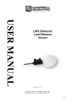
1
MPS-1
Dielectric Water Potential Sensor
Operator’s Manual
Version 3.0

Decagon Devices, Inc.
2365 NE Hopkins Court
Pullman, WA 99163
Tel: (509) 332-2756
Fax: (509) 332-5158
www.decagon.com
Copyright ©2008-2009
Decagon Devices, Inc.
All Rights Reserved
Contents
1. Introduction.................................. 1
Contact Information....................................... 1
Warranty Information..................................... 1
Seller’s Liability................................................ 1
2. About the MPS-1........................... 3
Specifications.................................................... 3
3. Theory........................................... 5
4. Installing the Sensors................... 8
5. Collecting Data............................. 9
Datalogger Requirements............................... 9
6. Calibration.................................. 13
Units Conversions......................................... 13
7. Handling and Care......................14
MPS-1 in Frozen Soils.................................. 14
8. Sample Programs.........................17
Appendix A..................................... 21
Declaration of Conformity........................... 21
i
Water Potential Probe
1. Introduction
1. Introduction
Thank you for choosing the Dielectric Water Potential
Sensor, model MPS-1 for measuring soil water potential.
This manual is designed to help you understand the sensor’s features, and how to use this device successfully.
In the engineering community, the term soil suction is
commonly used instead of soil water potential. Soil water
potential is simply the negative of soil suction and will be
used throughout the remainder of this manual.
Contact Information
To contact Decagon for customer support or questions:
E-mail:
[email protected]
[email protected]
Fax: (509) 332-5158
Telephone:
1-800-755-2751 (USA and Canada Only)
1-509-332-2756 International
Our Customer Support and Sales Representatives are available Monday thru Friday, 8am-5pm Pacific Time.
NOTE: With any correspondence please include your name, contact
information, instrument serial number(s), and a description of your
problem or question.
1
Water Potential Probe
1. Introduction
Warranty Information
The Dielectric Water Potential Sensor has a 30-day satisfaction guarantee and a one-year warranty.
Seller’s Liability
Seller warrants new equipment of its own manufacture
against defective workmanship and materials for a period
of one year from date of receipt of equipment (the results
of ordinary wear and tear, neglect, misuse, accident and
excessive deterioration due to corrosion from any cause
are not to be considered a defect); but Seller’s liability for
defective parts shall in no event exceed the furnishing of
replacement parts F.O.B. the factory where originally manufactured. Material and equipment covered hereby which
is not manufactured by Seller shall be covered only by the
warranty of its manufacturer. Seller shall not be liable to
Buyer for loss, damage or injuries to persons (including
death), or to property or things of whatsoever kind (including, but not without limitation, loss of anticipated profits),
occasioned by or arising out of the installation, operation,
use, misuse, nonuse, repair, or replacement of said material
and equipment, or out of the use of any method or process for which the same may be employed. The use of this
equipment constitutes Buyer’s acceptance of the terms set
forth in this warranty. There are no understandings, representations, or warranties of any kind, express, implied,
statutory or otherwise (including, but without limitation,
the implied warranties of merchantability and fitness for a
particular purpose), not expressly set forth herein.
2
Water Potential Probe
2. About the MPS-1
2. About the MPS-1
The MPS-1 measures the water potential of soil and
other porous materials. The MPS-1 has a low power requirement which makes it an ideal sensor for permanent burial in the soil and continuous reading with a
datalogger or periodic reading with a handheld reader.
Specifications
Range: -10 to -500 kPa (pF 2 to pF 3.71)
Accuracy: ±40% of reading if no user calibration
is performed
Resolution: 1 kPa from -10 to -100 kPa
4 kPa from -100 to -500 kPa
Measurement Time: 10 ms (milliseconds)
Power requirements: 2 to 5 V DC @ 25 mA
Output: 500 to 1000 mV DC independent of excitation
voltage
Operating Temperature: 0 °C to +50 °C
Survival Temperature: -40 °C 50 °C
Sensor Dimensions: 75 mm x 32 mm x 15mm
3
Water Potential Probe
2. About the MPS-1
Connector types: 3.5 mm “stereo”
plug or stripped and tinned lead wires (3)
Cable length: Standard cable length is 5 m. Extension
cables and custom cable lengths available upon request,
up to a maximum length of 15 m.
Datalogger Compatibility: (not exclusive)
Decagon: Em50, Em50R (firmware version 1.14)
Campbell Scientific: CR10X, 21X, 23X, CR1000, CR3000,
Etc.
Other: Any data acquisition system capable of switched 2
to 5 V excitation and single ended voltage measurement at
12 bit or better resolution
Software Compatibility:
ECH2O Utility 1.09 or later
ECH2O Utility Mobile 1.17 or later
ECH2O Data Trac 2.77 or later
4
Water Potential Probe
3. Theory
3. Theory
There are two basic parameters that describe the state of
water in soil: one is soil water content, or the amount of
water per unit of soil, and the other is soil water potential,
or the energy state of water in the soil. Although water
content is useful when trying to describe the water balance of a soil, i.e. how much water is moving in, out, or
being stored, water potential is often preferred over water
content because it shows how water will move in a soil or
from the soil to the plant. In addition, water potential can
be used to determine plant availability of water, determine
soil stress, and simply schedule irrigation, among other
things.
All soil water potential measurement techniques measure
the potential energy of water in equilibrium with water in
the soil. The Second Law of Thermodynamics states that
connected systems with differing energy levels will move
toward an equilibrium energy level. Thus, if an object
comes into hydraulic contact with the soil, the water potential of the object will come into equilibrium with the
soil water potential. Examples of instruments that make
use of this principal are tensiometers, which measure the
potential energy of a liquid water reservoir in equilibrium
with the soil water (liquid equilibration), and psychrometers/dewpoint hygrometers, which measure the potential
energy of water vapor in equilibrium with the soil water
(vapor equilibration).
Another category of water potential sensors use a solid
matrix equilibration technique to measure the water poten5
Water Potential Probe
3. Theory
tial of the soil. This technique introduces a known material
with a static matrix of pores into the soil and allows it to
come into hydraulic equilibrium according to the Second
Law of Thermodynamics noted above. Because the two
are in equilibrium, measuring the water potential of the
material will give the water potential of the soil. Historically, instruments have measured the thermal conductivity
or electrical conductivity of the solid matrix to determine
its water potential with varying degrees of success.
The MPS-1 uses the same principle, but instead measures
the dielectric permittivity of a solid matrix - porous ceramic
disks - to determine its water potential. The dielectric permittivity of air, the solid ceramic, and water are 1, 5, and
80 respectively. So, the dielectric permittivity of the porous
ceramic disks is highly dependent on the amount of water
that is present in the pore spaces of the ceramic. Thus, by
measuring the dielectric permittivity of the ceramic disks,
a wide range of water contents can be resolved.
Water content and water potential are related by a relationship unique to a given material. The ceramic used with the
MPS-1 has a wide pore size distribution and is consistent
between disks. So, if the water content of the ceramic is
measured accurately, along with a measurement of actual
water potential, then a calibration curve is generated that
will give a standard calibration for the MPS-1 in terms of
water potential. This calibration is not dependent on the
type of soil into which the MPS-1 is installed.
The total soil water potential (Yt) is made up of four water
potential components:
6
Water Potential Probe
3. Theory
Yt = Yp + Yg + Yo + Ym
where the subscripts p, g, o, and m are pressure, gravitational, osmotic, and matric respectively. Of these four
components, only Yo and Ym are important and often
measured in soil. Yo arises from dissolved salts in the soil,
and only becomes important if a semi permeable barrier
is present that prevents ionic movement (e.g. plant roots,
cell membranes). Ym arises from the attraction of water to
the soil particles, and is the most important component of
water potential in all but the most salt affected soils. The
MPS-1 only measures the matric potential of the soil (Ym).
In highly salt affected soils, it may be necessary to quantify
Yo independently if measures of soil water potential relating to biological activity are being conducted.
7
Water Potential Probe
4. Installing the Sensors
4. Installing the Sensors
Because it measures water potential, the MPS-1 is not as
sensitive to air gaps or soil disturbance as water content
sensors. It does, however, need good hydraulic contact
with the surrounding soil. The preferred method for installing the sensor is to take some native soil, wet it, and
pack it in a ball around the entire MPS-1, making sure that
the moist soil is in contact will all surfaces of the ceramic.
The sensor and moist soil are then packed into the soil at
the desired depth.
In sandy soils, the soil may not adhere to the sensor even
when wet. In this case the sensor can be packed into soil at
the bottom of a hole dug to the desired installation depth.
Again, care should be taken to pack the sandy soil around
the sensor with good contact to all ceramic surfaces.
After installing the sensor and moist soil, the hole that was
excavated to bury the sensor at depth should be back-filled
with care taken to re-pack the soil back to its native bulk
density. It is best to leave at least six inches of sensor cable
beneath the soil before bringing the cable to the surface.
The cable should never be bent in a tight radius as it leaves
the sensor body. At least four inches of cable should exit
the sensor body in a straight line before bending the cable.
8
Water Potential Probe
5. Collecting Data
5. Collecting Data
Datalogger Requirements
The MPS-1 is designed to work most efficiently with Decagon’s Em50 or Em50R dataloggers or our ProCheck handheld readout. They can, however, be adapted for use with
other dataloggers, such as those from Campbell Scientific,
Inc., for example. The MPS-1 requires an excitation voltage in the range of 2 to 5 volts. It produces an output voltage that is related to the water potential of the soil in which
it is buried, and ranges between approximately 0.5 to 1 V
DC. The output of the MPS-1 is independent of the excitation voltage between 2 and 5V. Any datalogger which
can produce a 2 to 5V excitation with approximately 10
millisecond duration and read a volt-level signal with 12-bit
or better resolution should be compatible with the MPS-1.
The current requirement for the MPS-1 is 25mA.
Note: MPS-1 is intended only for use with dataloggers and readout
devices which can provide short excitation pulses, leaving the sensor
turned off most of the time. Continuous excitation not only wastes
battery power, but may, under certain circumstances, cause the sensor
to exceed government specified limits on electromagnetic emissions.
Using the MPS-1 with Em50/Em50R dataloggers
The MPS-1 is designed for very easy integration into the
Em50 based datalogging system. Simply plug the stereo
plug into one of the five ports on the Em50/Em50R, use
ECH2O Utility or DataTrac software to configure that
9
Water Potential Probe
5. Collecting Data
port for an MPS-1 and set a measurement interval for the
logger. For more detailed instructions on configuring the
Em50/Em50R, consult your Em50/Em50R user manual.
3.5mm Stereo Plug Wiring
MPS-1 sensors used with Decagon loggers come with
a 3.5mm “stereo plug” connector. The stereo plug allows for rapid connection directly to Decagon’s Em50
and Em50R logger (Firmware R1.14 or greater) and
to the hand-held ProCheck. Below is a diagram showing the wiring configuration for this connector.
Analog
out
Ground
Excitation
Extending sensor cables
Decagon offers 10-foot (3m) extension cables for use with
the stereo plug type MPS-1 sensors. You can safely connect up to four of the 10-foot cables without significant
signal attenuation. For field applications, it is critical to
seal the connections from the elements to maintain a good
connection and to prevent corrosion. It is imperative that
these connections are checked before the sensor is buried.
On the Decagon website you can access a step by step
photo tutorial of how to seal the connection. To access
this file go to www.decagon.com/liturature/app_notes
10
Water Potential Probe
5. Collecting Data
and click on the Wire Splicing and Sealing Technique for
Soil Moisture Sensors.
MPS-1 sensors with stereo plug ends can be made with
custom cable lengths, up to 50 ft (15m) on a per foot fee
basis. This option gets around the need for waterproofing
connections.
Connecting to a non-Decagon Datalogger
MPS-1 sensors for use with non-Decagon dataloggers
come pre-configured with stripped and tinned lead wires
at the customer’s request. Below is a diagram showing the
wiring configuration for this connection
Analog out (Red)
Ground (Bare)
Sensor cable
Excitation (White)
MPS-1 sensors with stripped and tinned cable option can
be made with custom cable lengths up to 50ft (15m) on a
per foot fee basis. This option gets around the need for
splicing cables.
Connect the wires to the datalogger as shown, with the
supply wire (white) connected to the excitation, the analog
out wire (red) to an analog input, and the bare ground wire
to ground as seen below.
11
Water Potential Probe
6. Calibration
Supply
Exc.
Analog
out
H
Analog
In
Ground
L
G
Datalogger
If your MPS-1 is equipped with the standard 3.5mm plug,
and you wish to connect it to a non-Decagon datalogger,
you have two options. First, you can clip off the plug on
the sensor cable, strip and tin the wires, and wire it directly
into the datalogger. This has the advantage of creating a
direct connection with no chance of the sensor becoming
un-plugged; however, it then cannot be used in the future
with a Decagon Em50 or Em50R logger.
The other option is to obtain an adapter cable from Decagon. The 3-wire sensor adapter cable has a connector for
the sensor jack on one end, and three wires on the other
end for connection to a datalogger (this type of wire is
often referred to as a “pigtail” adapter). Both the stripped
and tinned adapter cable wires have the same termination
as seen above; the white wire is excitation, red is output,
and the bare wire is ground.
12
Water Potential Probe
6. Calibration
6. Calibration
The MPS-1 does not require any calibration by
the user. Each MPS-1 sensor is calibrated at Decagon to
equate the relationship between sensor output and
soil water potential. With Decagon’s Em50, Em50R,
and ProCheck readers, this relationship is:
With other data acquisition equipment, if the sensor
is excited with a voltage level between 2 and 5V, the
relationship is:
Note that this calibration is only valid from -10
to -500 kPa. The MPS-1 has sensitivity below this
range, but the calibration equations provided above
may not result in accurate measurements of water
potential below -500 kPa.
Units Conversions
Other commonly used measures of water potential
are MPa (megapascals), bars and pF.
1 MPa = 1000 kPa
1 Bar = 100 kPa
1 pF = log10(-10.2*kPa)
13
Water Potential Probe
7. Handling and Care
7. Handling and Care
The MPS-1 sensor measures the water potential of two engineered ceramic disks sandwiched between stainless steel
screens and the MPS-1 circuit board. The ceramic disks
are somewhat brittle, and can chip or crack if abused. The
metal screens afford the disks some amount of protection,
but sharp trauma on the disk edges or massive impact (such
as dropping the sensor onto a hard surface) can cause the
ceramic to break. One or two small chips on the edge of
the disk will not affect the sensor accuracy significantly.
However, a cracked ceramic will create a loss of accuracy.
For the MPS-1 to accurately measure water potential, the
ceramic disks must readily take up water. If the ceramic
is exposed to oils or other hydrophobic substances, then
the ability of the disks to take up water from the soil can
be compromised leading to slow equilibration times and/
or loss of accuracy. It is recommended that exposure of
the ceramic material to skin oils be minimized as much
as is conveniently possible, and it is highly recommended
that the disks not be handled with greasy hands, or otherwise exposed to synthetic oils or other hydrophobic compounds.
MPS-1 in Frozen Soils
The MPS-1 measures the dielectric permittivity of two ceramic disks to measure their water content and then derive
their water potential. The dielectric permittivity of water in
14
Water Potential Probe
7. Handling and Care
the ceramic disks is 80 compared to a dielectric permittivity
of ~5 for the ceramic material, and 1 for air. When water
freezes to ice, the dielectric permittivity drops to 5 at the
frequency of the MPS-1 measurement meaning that the
MPS-1 can no longer accurately measure the water in the
ceramic. Under frozen soil conditions, the MPS-1 will not
accurately measure the water potential of soil. However,
under frozen soil conditions, the water potential of the soil
can be measured simply by measuring the soil temperature
accurately (Koopmans and Miller, 1966). For each 1° C decrease in temperature below 0° C, the water potential in
the soil decreases by ~1200 kPa. Spaans and Baker (1996)
showed that this relationship is valid in field soils for water
potentials below about -50 kPa.
Rigorous testing indicates that the MPS-1 ceramic disks
are unaffected by repeated freeze-thaw cycles. Several sensors were equilibrated in saturated soil, and then subjected
to numerous freeze-thaw cycles in a temperature control
chamber. The freezing rate of the soil containers was at
least an order of magnitude faster than could be achieved
in field soil under natural conditions. At several points
during the test, and at the end of the test, the ceramic disks
were evaluated for damage due to repeated rapid freezing
with pore spaces full of water. None of the ceramic disks
showed any signs of physical damage, and none of the
sensors showed any significant change in output due to the
freezing tests.
15
Water Potential Probe
7. Handling and Care
References:
Koopmans, R. W. R., and R. D. Miller 1966. Soil freezing
and soil water characteristic curves, Soil Sci. Soc. Am.
Proc., 30, 680– 685, 1966.
Spaans, E. J. A., and J. M. Baker 1996. The soil freezing
characteristic: Its measurement and similarity to the
soil moisture characteristic, Soil Sci. Soc. Am. J., 60,
13– 19, 1996.
16
Water Potential Probe
8. Sample Programs
8. Sample Programs
The following programs are examples that can be used with
dataloggers from Campbell Scientific. The first program is
for a CR10X datalogger, but can be easily adapted to other
“Edlog” type loggers. The second program is for a CR1000
datalogger, but can be easily adapted for other “CRBasic”
type loggers. Note that the MPS-1 will draw up to 25 mA
of current while excited. On most Campbell Scientific dataloggers, each excitation port will only source 25 mA of
current, meaning that only one MPS-1 can be excited by
any one excitation port without the use of a multiplexer.
Edlog Type program
;{CR10X}
;Sample program for reading MPS-1 with CR10X
;
;Wiring:
;White - Excitaiton - E1
;Red - Analog out - SE CH1
;Bare - ground - AG
;
;output is water potential in units of kPa
*Table 1 Program
01: 10
Execution Interval (seconds)
17
Water Potential Probe
8. Sample Programs
1: Excite-Delay (SE) (P4)
1: 1
Reps
2: 5
2500 mV Slow Range
3: 1
SE Channel
4: 1
Excite all reps w/Exchan 1
5: 1
Delay (0.01 sec units)
6: 2500 mV Excitation
7: 1
Loc [ MPS1_mV ]
8: 1.0
Multiplier
9: 0.0
Offset
2: Z=X*Y (P36)
1: 1
X Loc [ MPS1_mV ]
2: 1
Y Loc [ MPS1_mV ]
3: 2
Z Loc [ mV_sq ]
3: Z=F x 10^n (P30)
1: 4.8
F
2: -5
n, Exponent of 10
3: 3
Z Loc [ C2
]
4: Z=X*Y (P36)
1: 3
X Loc [ C2
]
2: 2
Y Loc [ mV_sq ]
3: 4
Z Loc [ term1 ]
5: Z=X*F (P37)
1: 1
X Loc [ MPS1_mV ]
2: -0.0846 F
3: 5
Z Loc [ term2 ]
6: Z=X+Y (P33)
18
Water Potential Probe
8. Sample Programs
1: 4
2: 5
3: 6
X Loc [ term1
Y Loc [ term2
Z Loc [ power
7: Z=X+F (P34)
1: 6
X Loc [ power
2: 39.45 F
3: 6
Z Loc [ power
]
]
]
]
]
8: Z=EXP(X) (P41)
1: 6
X Loc [ power ]
2: 7
Z Loc [ MPS1_kPa ]
9: Z=X*F (P37)
1: 7
X Loc [ MPS1_kPa ]
2: -1
F
3: 7
Z Loc [ MPS1_kPa ]
10: If time is (P92)
1: 0000 Minutes (Seconds --) into a
2: 60
Interval (same units as above)
3: 10
Set Output Flag High (Flag 0)
11: Real Time (P77)^7092
1: 1110 Year,Day,Hour/Minute (midnight = 0000)
12: Average (P71)^2789
1: 1
Reps
2: 7
Loc [ MPS1_kPa ]
*Table 2 Program
02: 0.0000 Execution Interval (seconds)
19
Water Potential Probe
8. Sample Programs
*Table 3 Subroutines
End Program
CRBasic type program
‘CR1000 Series Datalogger
‘Sample program to read MPS-1 sensor with CR1000
‘wiring:
‘white - excitation - EX1
‘red - analog out - SE CH1
‘bare - ground - ground
Public MPS1_mV, MPS1_kPa
DataTable (table1,1,-1)
DataInterval (0,60,Min,10)
Average (1,MPS1_kPa,FP2,False)
EndTable
BeginProg
Scan (10,Sec,0,0)
BrHalf (MPS1_mV,1,mV2500,1,Vx1,1,2500, False
10000,_60Hz,2500,0)
MPS1_kPa = -EXP(0.000048 * MPS1_mV^2 - 0.0846 * MPS1_mV + 39.45)
CallTable table1
NextScan
EndProg
20
Water Potential Probe
Appendix A
Appendix A
Declaration of Conformity
Application of Council Directive: 89/336/EE6
Standards to which conformity is declared:
EN61326 :1998 EN51022 : 1998
Manufacturer’s Name:
Decagon Devices, Inc.
2365 NE Hopkins Court
Pullman, WA 99163 USA
Type of Equipment:
Dielectric Water Potential Sensor Model Number: MPS-1
Year of First Manufacture: 2007
This is to certify that the dielectric water potential sensor,
manufactured by Decagon Devices, Inc., a corporation
based in Pullman, Washington, USA meets or exceeds the
standards for CE compliance as per the Council Directives noted above. All instruments are built at the factory
at Decagon and pertinent testing documentation is freely
available for verification.
21
Water Potential Probe
Index
Index
A
About the MPS-1 4
Adapter cable 13
C
Cable length 5
Calibration 14
Campbell Scientific 5
Care 15
Ceramic disks 15
Compatibility 5
Conformity 22
Contact Information 2
Conversions 14
Corrosion 11
CR10X datalogger 18
Custom cable lengths 12
D
Datalogger Requirements 10
Dielectric permittivity 7
E
Em50R 10
E-mail 2
Energy of water 6
Extending sensor cables 11
22
Water Potential Probe
Index
F
Fax 2
Frozen Soils 15
H
Handling 15
Hydraulic contact 9
Hydrophobic substances 15
I
Installing the Sensors 9
L
Liability 2
M
Manufacturer 22
Model Number 22
N
Non-Decagon Datalogger 12
P
Power 4
ProCheck 10
Programs 18
R
References 16
S
23
Water Potential Probe
Index
Sandy soils 9
Soil water content 6
Soil water potential 6
Specifications 4
T
Telephone 2
Temperature 4
Tensiometers 6
W
Warranty 2
Water potential components 7
Waterproofing 11
Wiring configuration 11
24