1
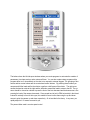
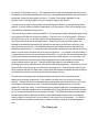
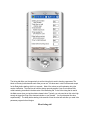
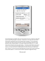
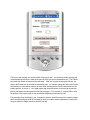
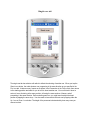
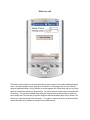
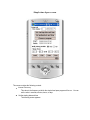
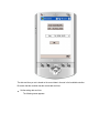
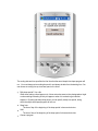
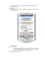
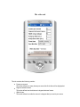
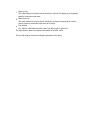
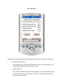
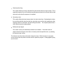
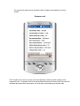
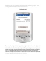
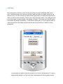
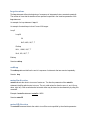
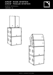
AutoMate 2.0 User Manual
The AutoMate hardware
The front panel
AutoMate's front panel contains two jacks, a power switch, a LED, and a Bluetooth antenna
connector.
The A jack
The A jack is where you plug in the shutter release cord. The Gadget Works provides
one free shutter release cord with every unit. You can purchase extra cords from The
Gadget Works or build your own. The jack is a standard three-connector 2.5 mm minijack. The three connectors on mini-plugs are called tip, ring, and sleeve. The sleeve is
the ground connector, the tip is the shutter connector, and the ring is the shutter halfpress connector. When a shutter release or half-press signal is sent to the camera, a
transistor closes the connection between the corresponding connector and ground.
The C jack
The C jack is where you plug in a sensor for use with the Triggered program feature. The
jack is a standard three-connector 2.5 mm mini-jack, just like the A jack. The sleeve is
ground, the tip is associated with trigger program 1 and the ring is associated with
trigger program 2. When a trigger connector is shorted to ground, the corresponding
trigger program is executed. See the section on Trigger events for more information.
The power switch
The power switch has three positions: On, Standby, and Off. However, only On and Off
are of use.
The LED
The LED should illuminate when you turn the power switch to the ON position, assuming
that AutoMate has batteries installed or is connected to an external DC power source.
The LED blinks when a program is being uploaded from the PDA. It also is turned off
while the shutter is being fired. This usually produces a short blink. However, if you are
doing a long bulb-mode exposure, the LED will be off for the entire period, which can be
deceiving if the period is quite long.
The Bluetooth antenna connector
The Bluetooth antenna connector is for a standard screw-on SMA Bluetooth antenna.
The Gadget Works provides one antenna free with every unit. AutoMate can function
quite well without an antenna if the PDA is within about 10 meters of the robot. The
antenna extends the range to about 100 meters.
The battery case
The battery case is on the rear of the robot. It has a door that lifts up. It holds 4 AA batteries,
which can be 1.2 V rechargeable or 1.5 V non-rechargeable batteries.
The external power port
On the side of the AutoMate robot there is a socket for attaching an external power supply.
Although AutoMate is very power efficient, there might be times when you want to use
something other than 4 AA batteries or you might want to provide temporary power while
changing the AA batteries. Through the external power port, you can supply power from a
switching power supply or a motorcycle battery or any source that provides 5 to 6 volts of DC
power. The power jack takes a standard 5.5 mm O.D. x 2.1 mm I.D. center-positive barrel
connector.
The base of the robot
The base of the robot contains a standard 1/4 20 threaded socket, identical to the socket found
on the base of most DSLR cameras. You typically attach the robot to a tripod using this socket.
The camera platform
The camera platform is where you attach your camera. It has a thumb-wheel attached to a 1/4
20 threaded bolt, identical to the bolts found on most tripods for DSLR cameras. The bolt is in a
slot that allows about one inch (2.5 cm) of front-to-back positional adjustment . It can be
advantageous to attach a quick-release mechanism to the bolt for rapid attaching and removing
of your camera. You might also consider attaching a swivel-tilt head, such as the Manfrotto
3229, which has a quick release mechanism and also allows you to tilt the camera through 170
degrees of vertical view.
Installing the AutoMate software
If you bought a PDA from The Gadget Works, you should not need to install the AutoMate
software, as it should be pre-installed. The PDA you got with AutoMate should also contain a SD
memory card containing the software in case you need to re-install it. You should make a copy
of the contents of the SD card for safe keeping. If you did not buy a PDA with AutoMate, you
still should have received a SD memory card containing the AutoMate software.
The AutoMate software consists of two CAB files, one for AutoMate 2.0 and one for Net
Compact Framework version 3.5 . The AutoMate 2.0 CAB file is named
AutoMate2.0.xxxx.yyyy.CAB, where xxxxx.yyyyy refer to the build number of the AutoMate
program. This build number also appears in Help > About AutoMate. There are three different
versions of the NetCF 3.5 CAB files that apply to three different versions of Windows Mobile.
For Pocket PC 2003, the correct CAB file is NETCFv35.ppc.armv4.cab. For Window Mobile 5 and
6, the correct CAB file is NETCFv35.wm.armv4i.cab. And for Windows CE, the correct CAB file is
NETCFv35.wce.armv4.cab. If the version you received is not the correct one for your PDA,
either notify The Gadget Works and we will send you the right one, or search the web for the
one you want. They are all freely available.
If you need to install or reinstall the AutoMate software, perform the following steps:
Copy the appropriate version of NetCF 3.5 CAB file to any folder on your PDA.
Copy the AutoMate 2.0 CAB file to any folder on your PDA.
Tap each of the two CAB files, one at a time. The order is not important. When you tap the
file, it installs the associated software and then deletes the CAB file. We don't know why
Microsoft does it this way, but they do.
Now AutoMate is installed on your PDA in a folder named TheGadgetWorks, which is located in
My Device > Program Files. You can use the File Explorer to navigate to that folder. The File
Explorer usually appears under the Start menu but if it does not, tap Start > Programs and find it
there. After you do this one time, it should appear in the Start menu from then on. But do not
launch AutoMate until you read the following sections.
Running AutoMate the first time
You need to do a few things before you run AutoMate for the first time. How much you need to do
depends on whether you bought a PDA from The Gadget Works or not. Whether you bought your
PDA from The Gadget Works or not, you need to read Appendix A on using your PDA to control the
robot. In that Appendix there is a warning not to check a certain check box and it will save you a lot
of time and bother if you read and understand that information. Also, you might want to read
Appendix B for tips on conserving power drainage of your PDA batteries.
If you bought your PDA from The Gadget Works, you only need to do two things before you launch
AutoMate for the first time. You need to turn on the PDA's Bluetooth radio and you need to power
up the robot (if you don't see the green LED, it isn't on -maybe you forgot to put batteries in it?). To
turn the PDA Bluetooth radio on, go to the Today screen (tap the Windows icon at the top left of
every screen and then tap Today) , then tap the Bluetooth icon in the lower right corner of the
Today screen. A menu appears that has the option to either turn the Bluetooth radio on or off. If
you Bluetooth icon on the Today, either your PDA does not have a Bluetooth radio or the radio was
disabled and you need to do a hard reset to re-enable it. This is a rare occurrence but we have seen
it happen in transit a few time for unknown reasons, perhaps because of passing through strong XRay equipment. Read Appendix A if you have this problem.
If you did not buy your PDA from The Gadget Works, you need to do one other thing before
launching AutoMate for the first time. You need to find out what the outgoing Bluetooth COM port
is, because you will be asked to set it the first time you run AutoMate. If you run AutoMate before
knowing that information, you will not be able to connect to the robot and you will also have to
delete the file that the program created where it saved the COM port information. This is explained
in more detail in Appendix A. Appendix A is also where you can find information on how to find the
COM port for various versions of Windows Mobile. Microsoft made it harder and harder as they
released newer and newer versions. Go figure.
The first things you see after launching AutoMate
Other than a request to set the Bluetooth COM port, which is already done for you if you bought the
PDA from The Gadget Works, the first thing you should see when launching AutoMate is the
Bluetooth Browser. This is a window that shows all the Bluetooth devices in the near neighborhood,
including AutoMate if it is nearby and turned on. Actually, sometimes it will appear even if it isn't
turned on because the PDA caches the connection. When this happens you will get an odd error
message when you tap the AutoMate icon, saying that it can't find the Serial Port on the robot. If
this happens, answer Yes to the Try Again question, turn on the robot, and then when the
Bluetooth Browser screen reappears, tap the refresh icon in the lower left corner. Now you can tap
the AutoMate icon and it will find the Serial Port and connect.
Unless you have a file named FirmwareUpdate in the root directory of your PDA, the next screen
you see is the main screen. If you do have a FirmwareUpdate file in the root directory, you will be
asked if you want to update the firmware. It is only something you need to do once, so you can
answer No once you have done the update. You can also eliminate that question by deleting or
renaming the file.
The Main Screen
The buttons down the left side open windows where you create programs to automate the creation of
panoramas, time-lapse movies, and a custom self-timer. You can also create custom programs with a
program editor to run immediately on the robot or to respond to external triggers. The grouping of four
arrows and two center buttons are the remote head control buttons. By pressing those buttons you
can pan and tilt the head and fire the shutter or perform a half-press of the shutter. The right arrow
causes the head to rotate to the right and the left button causes the head to rotate to the left. The up
arrow should be viewed as a button to press the front of the lens downward and the down arrow is like
pressing the back of the camera downwards. Since people tend to hold a PDA horizontally in their hand
instead of vertically in front of their eyes, this method is more intuitive than using the up and down
arrows to point the camera up and down respectively. Or at least that is the theory. In any case, you
rapidly adjust to it if it seems reversed to you.
The percent slider scale is a motor speed control .
The File menu contains a single menu entry, Exit, which you use to exit the application. Note that
closing the window does not exit the application. You must use File > Exit.
The Edit menu contains, two entries, "Timing Parameters" and "Camera and Lens". Tapping either one
of these opens the Panorama window with the appropriate tab in front.
The Connect menu has one entry, "Connect to robot". Use this if the connection to the robot is lost.
Another alternative is to exit the application and re-launch it.
The Stop menu contains three entries, "Trigger Program 1", "Trigger Program 2", and "Time-lapse
program". Tapping any one of these sends a signal to the robot to terminate the corresponding
program.
The Help menu has only an About entry. Tap Help > About to find the build number of the AutoMate
program.
The Debug menu is inactive.
The Panorama window
When you tap Panorama on the main screen, you get the Panorama window with all its tabs. The tabs
include Camera/Lens, Overlap, Timing, Bracket, First row, Single row, and Multi-row. The following
screens show each of the tabs:
The Camera/Lens tab
The Camera/Lens tab contains entry boxes where you can give the program the information it needs to
compute trial values for the motor timing required to get the desired percentage of overlap between
images.
Focal length describes the lens you are using. If you use a tele-extender, multiply the focal length of the
lens by the multiplier factor of the tele-extender.
Crop factor refers to the relative size of the sensor of a digital camera. If the sensor is full frame, such as
with the Canon 5D, the crop factor is 1.0. If the sensor is smaller, the crop factor is larger. For example,
the crop factor for a Canon 20D or 10D is 1.6. Refer to your camera manual to find the correct value for
your camera.
Aspect ratio refers to the ratio of width to height of the sensor. For example, for 35 mm film and many
digital sensors, the aspect ratio is 1.5.
Orientation refers to how the camera is mounted on AutoMate. The two choices are Landscape (wide)
and Portrait (tall).
The trial values that are computed when you change any of the values in the Camera/Lens tab appear in
the Overlap tab.
The Overlap tab
When you tap "Get trial values", new values are computed for Right, Left, Up, and Down based on the
values in the Camera/Lens tab and the two overlap values. These four values control how far the head
moves per frame in each direction. The trial values may or may not be the final values you want to use,
however. You need to shoot test shots to see if the overlap between frames is sufficient for getting a
good stitch. To shoot test frames, choose the direction of motion you want to test from the drop-down
list, then tap "Test overlap, moving:". This causes the robot to take one photograph at rest, then move
the head by an amount determined by the value in the corresponding direction box, then take a second
photograph, followed by moving back one frame. To decide if the overlap is adequate for your
purposes, view the two photographs using your camera's image review feature.
You may or may not want to closely match the left-moving frame distance to the right-moving frame
distance. If you are shooting a single-row panorama, it is of little concern. But if you are taking a multirow panorama, it depends on how you do it.
There are two ways to take a multi-row panorama. One way requires closely matching the right-moving
frame distance with the left-moving frame distance. The other way, it is not so important. When you
do it the first way, once you know the number of rows and frames per row, you point the camera at
one of the corners of the scene and begin to shoot. When done this way, the robot shoots a row,
followed by automatically incrementing to the next row and working its way back, continuing in this
way until all the rows are shot. (The method for determining the number of frames and rows in the
panorama is explained later.) It is important when shooting the panorama this way that the left-moving
frames are quite close to the same size as the right-moving frames. If you decide to use this method, it
is a good idea to shoot two trial rows with quite a few frames. You can then pick the direction that gives
you the most desirable overlap and then adjust the value for the other direction. You can make a very
accurate adjustment by measuring the number of degrees that the head traveled in both directions,
using the degree scale on the robot. Then with a little simple math you can compute by what
percentage you need to adjust the value in the direction that needs adjustment. Recall that you do not
need to do this in the field, nor do you need to do it more than once. Once you get the values to your
liking, save them with the File >Save menu, using a name that identifies the camera and lens so that you
can reload those values the next time you use the same camera and lens.
The other way of shooting a multi-row panorama does not require that the frame sizes in both
directions are of exactly the same size. In this method, you shoot every row moving in the same
direction. The head moves back to the same starting position after each row and waits for you to tell it
to increment to and shoot the next row. During the pause after the head returns, you have the
opportunity, should you need it, to tap the arrow keys to bring the head to the exact starting location
for every row, using the degree scale on the AutoMate robot. It typically takes no more than 2 seconds
per row to bring the head to the correct location if needed. This method also offers some advantages
over the other method, in particular the ability to make adjustments between rows or to change the
camera's battery or memory card, or just to reshoot a row or part of a row if necessary. So, while it is
less automated, this method is easier to set up, easier to interrupt, and easier to get well-registered
rows.
The Timing tab
The timing tab offers you the opportunity to set the timing that is used in shooting a panorama. The
labels on the entry boxes describe each value you can set. All values are in units of milliseconds except
for the Delay before starting, which is in seconds. Most of the values are self-explanatory but a few
require clarification. The total time to hold the shutter open only applies if you do not choose Bulbmode bracketing, described in the discussion of the Bracketing tab. It also is the timing that is used in
the Main screen when you tap the shutter release button. Typically, you only need to set this value high
enough to trigger the firing of the electronic shutter on your camera. You can determine this value
experimentally. The delay before starting is the amount of time the robot will wait after you send it the
panorama program before it begins.
Bracketing tab
The bracketing feature in AutoMate makes it the most powerful instrument in existence for making high
dynamic range (HDR) photographs or panoramas. It depends on the user setting the camera to Bulb
mode and then controlling the amount of time that the shutter is held open. The user chooses the
center speed, the number of exposures per node, the number of stops between exposures, and the
sequence in which to take the exposures. The number of exposures can range from 1 to 11, with as
many exposures taken below the center speed as above. The number of stops between shots can be 0,
1/3, 1/2, 1 1/2, or 2. There are several sequence patterns you can choose from. If you specify that the
camera is not in Bulb mode, there is no bracketing but you can still set the number of exposures per
node. In this way, you can use the camera's bracketing feature and simply fire the shutter enough times
to shoot all the exposures. You can also use the number of exposures to trigger Mirror-lockup.
First row tab
The first row tab is where you set the number of frames per row. You do this by actually shooting the
row and pressing Stop when it reaches the point at which you want to terminate the row. The Frames
box shows the number of frames as they are taken. After you complete shooting the first row, the
value in the Frames box will be used for subsequent rows. You can also change the value in the Frames
box and the new value will be used for the rows. After shooting the first row, the head returns to the
starting position, or near to it. You might need to tap the arrow buttons on the next tab to precisely
position the head in the same place that the first row began. For this reason, it is a good idea to note
the position of the degree scale on the robot before beginning to shoot the first row.
This procedure does two things for you. It shoots the first row, which there may be no need to repeat,
and it also determines the width of the scene for which you want to create a panorama. From this tab
you go to either the Single row tab or the Multi-row tab.
Single row tab
The single row tab has a button with which to initiate the shooting of another row. When you tap the
Shoot a row button, the robot shoots a row, progressing in the same direction as you specified in the
First row tab. It takes as many frames as are shown in the Frames box in the First row tab, then returns
to the starting position and waits for you to tell it to shoot another row. You use this tab to shoot a
series of rows, all starting at the same position, all having the same number of frames, and all
proceeding in the same direction. Before shooting each row, you might need to adjust the head
position by tapping the arrow keys. You also need to increment to the next row by tapping either the
Up 1 row or Down 1 row button. The height of the panorama is determined by how many rows you
choose to shoot.
Multi-row tab
The Multi-row tab is where you command the robot to shoot a series of rows without waiting between
rows. It zig-zags through the rows, going first one direction, incrementing to the next row, then the
going the opposite direction. During shooting, a window appears with a Stop button that you can tap to
pause or terminate the shooting of the panorama. You set the number of rows and you can do this one
of two ways. You can set an arbitrarily high value and simply stop the panorama when you think you
have enough rows. The other way is to go the Single row tab and repeatedly tap the Up or Down 1 row
tab until you reach the vertical limit of the scene. You need to count the rows as you do this and then
enter that number in the Number of rows box on the Multi-row tab.
The time-lapse features
There are two time-lapse features in AutoMate. On the main screen, you can tap either Simple TL or
Panning TL, depending on what kind of time-lapse movie you want to make.
Simple Time-lapse
The simple time-lapse feature is primarily designed for making time-lapse movies while the head
remains stationary, but it can also use the custom programming feature to move the head. Stationary
time-lapse movies are appropriate for such things as shooting a flower blooming or clouds scudding
across the sky or a construction site progressing from day to day.
To show the window for this feature, tap Simple TL, which displays the following screen
Simple time-lapse screen
This screen contains the following controls:
Interval: Run every
This value is the frequency at which the simple time-lapse program will be run. You can
set the units in seconds, minutes, hours, or days.
Set the starting date and time
The following screen appears:
The date and time you set is based on the current date in time set in the handheld controller.
Be certain that the controller has the correct date and time.
Set the ending date and time
The following screen appears:
The ending date and time specifies the final time that the saved simple time-lapse program will
run. You must always set an ending time and it must always be later than the starting time. You
can choose an ending time up to several years in the future.
Daily sleep period? Yes or No
Often when making a time-lapse movie, it does not make sense to take photographs at night
or when nothing interesting is likely to happen or when it is too dark to get a decent
exposure. By setting the daily sleep period, you can specify a daily time period, during
which the simple time-lapse program will not run.
Sleep from:
The time of day of the beginning of the sleep period in hours and minutes
Until:
The time of day of the beginning of the sleep period in hours and minutes
Choose a program
When you touch the Choose a program button, a page appears that offers you the
following two options:
Exposure program
When you choose Exposure program, additional options appear for setting up a simple
time-lapse program:
The options include:
Number of exposures
You may want to take more than a single exposure at every interval. If you set
your camera to auto-bracketing, for example, you can take multiple images at
different exposures by firing the shutter multiple times.
Time between exposures in seconds
If you specify more than one exposure at each interval, you can also specify how
long to wait between exposures.
Precede with wakeup pulse
If you are taking a very long sequence of photographs, it is advantageous to let
the camera turn itself off between exposures, if your camera has the ability.
This is usually called entering sleep mode on the camera. The half-press of the
shutter wakes most the cameras up from sleep mode. If you choose this option,
a half-press signal is sent to the camera prior to taking the photograph to wake
it up from sleep.
Custom program
When you touch the Custom program button, the program editor appears. The
program editor is described in more detail later in the manual, but its function is to
define a set of commands that comprise the program that is executed at every interval.
Once you have entered all the parameters for the simple time-lapse program, you can run it
immediately by tapping the Run button.
There are also Save and Load buttons on that allow you to save the settings for the program and reload
them at another time. To save and load a custom program, use the program editor.
Panning time-lapse
This feature is still in the developmental phase. You are encouraged to try it and provide feedback. It is
designed to make panning time-lapse movies. You enter information about the final video and the
parameters of the shoot and the program generates a robot program to operate the motors and fire the
shutter with the appropriate timing to accomplish the task. After the robot completes the panning
sequence, you take the sequence of shots and combine them into a video in which time appears to be
accelerated. You can use any of various existing programs, such as QuickTime Pro, that combine
individual frames to construct a video.
This feature is, like the Panorama feature, organized as a set of tabs. There are tabs to define the target
video , to define the shoot, to display a summary of the controls, and one to calibrate the motors. The
first tab is the one in which you define the parameters of the video you will make from the sequence of
stills. To activate the panning feature, tap Panning TL on the main screen.
The video tab
This tab contains the following controls:
Frames per second
This value defines how many frames per second the final video will be displayed at.
Degrees between frames
This value defines how the distance in degrees between frames
Width of pan
This value defines how wide the scene is in degrees that you want to pan across
Ramp up time
This value defines how long the period should be in seconds for ramping up to the primary
speed of motion across the scene
Ramp down time
This value defines how long the period should be in seconds for ramping down from the
primary speed of motion across the scene to a full stop
Pan direction
This tells the robot which direction to pan, from left to right or right to left
The video duration value is a computed value based on the other values.
The next tab contains controls for setting the parameters of the shoot.
The shoot tab
This tab contains controls for defining timing information for the shoot. The controls on this tab are:
Wait time before shooting
This control allows you to define a delay between the time you send the program to the
robot and when it begins to take the sequence of shots
Shutter trigger time
This control determines how long to hold the shutter open. If you are using Bulb mode on
the camera, it will determine the exposure. Otherwise , it is simply the time it takes to
trigger the electronic shutter.
Wait time after firing
This control defines how long to wait after firing the shutter before moving the head. This is
especially important if you are shooting long exposures and want to be certain that the head
does not move before the exposure is completed.
Seconds per shot
This control defines the time between shots, the shot-to-shot time. Subtracting the shutter
time and the wait-after time from this time, gives the amount of time the head pauses after
stopping motion for each frame, but before firing the shutter. The computed pause time is
what varies during the ramping phases.
Milliseconds per degree
This control is set by the calibration procedure but is editable. If the total number of
degrees traveled during the shoot does not exactly match the specified value, try tweaking
this value to bring it closer.
This tab also has a Run button with which to begin the shoot. While the shoot is in progress,
you can also tap the Stop button to either cancel or pause the program. A dialog appears giving
you the choice.
The summary tab shows various calculations that the program made based on the values
entered.
Summary tab
The information on this screen is pretty much self-explanatory, with the possible exception of the
compression ratio. Compression ratio is the ratio between the frames per second in the final video and
the frames per second of the actual shoot. So it is the ratio of time speed-up of the final video.
The calibration tab is where you determine the speed of the head in milliseconds per degree. This is
necessary because some heads move faster or slower than others.
Calibration tab
The procedure for doing the calibration is simple. You set the direction of motion and the initial position
on the degree scale on the robot and tap Start calibrating. The head then moves for a specific amount
of time and then stops. When it stops, you simply enter the degree reading on the robot's degree scale
and tap Compute now! The program computes the number of milliseconds per degree and enters the
value on the Shoot tab and then uses that value in the program's calculations. Don't worry about
whether the starting and ending positions are on opposite sides of the zero marker on the degree scale the program figures that out and makes the correct calculation.
Self timer
Most cameras have a self-timer, but for the most part all they do is take a photograph after a given
delay. AutoMate expands on the self-timer concept by adding the ability to program the timer in new
and useful ways. As with the simple time-lapse and the trigger modes, you create the program that the
robot runs when the timer runs down. There are two modes of program creation. The simple mode lets
you set the number of exposures and the time between exposures. In the simple mode the LED flashes
one second before taking each exposure. In the custom program mode, you use the program editor to
create a program that can operate the motors and activate an external device, in addition to taking
photographs.
You can specify any number of seconds, minutes, hours, or day for the delay period. To create a
simple self-timer program, tap Typical self-timer, which displays the following added controls:
Now you set how many exposures to take and the time delay between exposures. If you tap the
Custom Program button, the custom program editor appears and you can create a program on
any complexity to execute when the specified delay time elapses. The custom program editor is
described later.
Event trigger programmer
There are two trigger inputs on the robot. Both of them are a part of the same port, Port A. The trigger
port is a standard three-lead mini-jack socket. The base is connected to ground, the ring is connected to
trigger 1 and the tip is connected to trigger 2. When a connection is made between trigger 1 and
ground, the robot runs a program associated with trigger 1 if it was sent one. When a connection is
made between trigger 2 and ground, the robot runs a program associated with trigger 2 if it was sent
one.
To create a program to respond to the event triggers, you use the Custom Program editor. Tapping
Trigger 1 opens the Custom Program editor where you can write or load a program. When you exit the
custom program editor back to the main screen, the program that you created is sent to the robot and
lies there in wait for the trigger event. The trigger events remain active until you send a command to
stop them. To deactivate a trigger program on the robot, select Trigger Program 1 or Trigger Program 2
from the Stop menu on the main page.
The Custom Program editor
You use the custom program editor to create programs that can be used in conjunction with any of the
following features:
Simple time-lapse
Self timer
Trigger programs
Run immediate mode
The Custom Program is simply a text editor window in which you enter program commands. You can
even create your programs on your PC and copy them to your PDA, eliminating the need for the editor
entirely.
If you use the editor in AutoMate 2.0, you can now select text and use Ctrl-C, Ctrl-X, Ctrl-V, as well as
on-screen Copy, Cut, and Paste buttons. You can also use Ctrl-Z to undo the last operation. There is a
Check button to activate the checking of the syntax of your program. Perhaps most useful is the Help
button that displays a list of all the commands and their formats and also copies a prototype of the
command into the clipboard, enabling you to paste the prototype into your program.
There is also a Run button that sends the program to the robot to be executed.
The new programming language is described below.
The AutoMate 2.0 Robot Control Language (RCL)
RCL is a very simple but powerful set of commands that tell the AutoMate robot what to do. Since
there aren’t many things that the robot can do, there aren’t many commands. The complete set of
commands follows:
HPdef Duration (half-press macro definition, duration in ms)
SHdef Duration, DoHalfPress (full-press macro definition – defaults to duration=600, doHalfPress = true)
rampDef direction, upDown, Duration, Steps, StartingSpeed, EndingSpeed (defaults to
duration=500, steps=5, starting speed=10, ending speed=100 for all direcions)
sub Name (subroutine definition)
endsub (end of subroutine)
loop Iterations (loop command)
endloop (end of loop)
dosub Name (subroutine command)
motorOn direction (Command to turns one of the motors on)
motorOff direction (Command to turns one of the motors off)
MV direction, duration, speed, useRampUp, useRampDown (Command to operate one of the motors)
MV direction, duration, useRampUp, useRampDown (Alternate command to operate one of the motors)
MV direction, duration (Alternate command to operate one of the motors)
pause duration (Command to do nothing for a period of time)
openContact whichContact (command to open a switch contact)
closecontact which contact (command to close a switch contact)
SH (command to perform the fpdef macro)
HP (command to perform the hpdef macro)
A program is a sequence of definitions and commands. Definitions define macros and subroutines that
are employed in commands. Commands are statements that tell the robot to do something, like fire the
shutter or move the head.
Macros are like a shorthand definition that you write once and then use one or more times in
commands. There are three macros in RCL, one to define ramping parameters, one to define shutter
release parameters, and one to define half-press parameters.
Subroutines are like macros except that they consist of many commands. You can include any
commands you want in a subroutine and you can include any number of subroutine insertions in your
program. You give every subroutine a unique name by which you refer to it in a doSub statement. The
doSub statement is effectively replaced by the sequence of commands in the subroutine definition. At
this time, subroutines do not have parameters, so they exist mostly to save you typing the identical code
multiple times.
One special statement that is neither a definition nor a command is the loop statement. Every loop
statement is matched by an endLoop statement. All the commands that lie between a loop statement
and its matching endLoop statement are executed by the robot repeatedly for a specified number of
times. You can nest loops up to five deep.
Program statement syntax
Every program statement has multiple parts. The first part is always the statement identifier, such as
SHDef or MV. After the statement identifier, there are a variable number of parameters that provide
more information about the statement. The number and types of parameters vary depending on the
statement. You can separate the parameters of a statement with spaces or commas or both.
Statements are case-insensitive. Some error messages show the statement that the error occurred in.
The statement in an error message might look different than the statement you wrote because the
editor strips all the spaces, places commas between statement parameters, and makes all the text lower
case.
If you place a single quote followed by a space at the head of a statement, the entire statement will be
treated as a comment and will be ignored.
You may have empty lines in your program, which will also be ignored.
Macro definitions
The following section describes the three macro definitions.
SHdef duration, half-press
SHdef is a macro for firing the shutter. You only include this definition once and every SH command
uses it to tell the robot how to fire the shutter. The SHdef macro affects every SH command until
another SHdef command appears in the program. The duration parameter of the statement must be a
number that defines the amount of time in milliseconds that the shutter contact should be closed. The
half-press parameter of the statement must be “true” or “false” or “t” or “f” and defines whether to
also close the half-press contact when firing the shutter. It does not hurt to close both contacts for any
camera that we know of, but it is required for Nikon cameras.
An example of a SHdef statement: SHdef 750, T
HPdef duration
HPdef is a macro for closing the half-press contact but not the full-press contact. You only include this
definition once and every HP command uses it to tell the robot how to do a half-press. The HPdef macro
affects every HP command until another HPdef command appears in the program. The duration
parameter of the statement must be a number that defines the amount of time in milliseconds that the
half-press contact should be closed.
An example of a HPdef statement: HPdef 500
rampDef direction, updown, duration, steps, lowSpeed, highSpeed
rampDef is a macro that defines the ramping (gradual speed change) parameters that MV (move)
commands can use to specify how a motor speed should be ramped up and down. The direction
parameter of the statement must be a single letter (u, d, r, or l) that indicates which motor motion this
macro applies to (up, down, right, or left). The updown parameter of the rampDef statement indicates
whether this macro applies to increasing (ramping up) the motor speed or decreasing (ramping down)
the motor speed. The two possible values are up and down. The duration parameter of the rampDef
macro defines how long in milliseconds that the ramp period should last. The steps parameter of the
rampDef macro defines how many steps there should be in the ramp. The lowSpeed parameter of the
rampDef macro defines the lower of the two speeds of the ramp as a percentage of full speed. The
highSpeed parameter of the rampDef macro defines the higher of the two speeds of the ramp, as a
percentage of full speed.
An example of a rampDef statement: rampDef R, down, 2000, 10, 10, 100
sub name
sub is the first statement of a user-written subroutine. The name parameter of the sub statement gives
the subroutine a name that can be used in a subsequent doSub command. Every Sub statement has a
matching endsub statement. All the statements between the sub and endsub statements form the
body of the subroutine.
See also: doSub, endsub
An example of a sub statement, its corresponding endsub statement, the body of the subroutine, and a
command that uses the subroutine:
Sub MoveShootMove
MV L, 100, 10000, T, false
SH
MV R, 100, 10000, true, true
endsub
…
dosub MoveShootMove
endSub
endsub defines the end of the preceding subroutine that starts with a sub statement.
See also: sub, doSub
Command statements
doSub name
The doSub statement is replaced at execution time by all the statements between the sub and endsub
statements of the subroutine named in the doSub statement. The name parameter of the doSub
statement identifies which subroutine to insert at this point in the program.
See also: sub, endsub
loop iterations
The loop statement defines the beginning of a sequence of statements that are executed repeatedly.
The number of times that the statements are repeated is specified in the iterations parameter of the
loop statement.
An example of a loop statement: loop 14
An example of nested loops to shoot 5 rows of 28 images:
Loop 5
Loop 28
SH
Mv R, 4000, 100, T, T
Endloop
MV L, 118000, 100, T, T
Mv U, 300, 100, T, T
Endloop
See also: endloop
endloop
The endloop statement defines the end of a sequence of statements that are executed repeatedly.
See also: loop
motorOn direction
motorOn directs the robot to turn one of motors on. The direction parameter of the motorOn
statement identifies which motor to turn on. The only valid values for direction are u,d,r, and l (for up,
down, right, left). Both a vertical and a horizontal motor may be turned on simultaneously by using this
command.
Example of motorOn statement: motorOn 10000
See also: motorOff
motorOff direction
The motorOff command directs the robot to turn off the motor specified by the direction parameter.
See also: motorOn
pause duration
The pause command instructs the robot to wait a specified number of milliseconds before executing
the next command. The duration parameter specifies the delay period.
closeContact whichContact
The closeContact statement directs the robot to close one of the two contact switches over which it has
control. The whichContact parameter specifies which contact to close. The valid choices are SH (shutter)
and HP (half press).
Example of closeContact statement: closeContact SH
See also: openContact
openContact whichContact
The openContact statement directs the robot to open one of the two contact switches over which it has
control. The whichContact parameter specifies which contact to open. The valid choices are SH (shutter)
and HP (half press).
Example of OPENontact statement: OPENContact HP
See also: closeContact
SH
The SH statement directs the robot to perform a shutter release process as defined by the most recent
SHdef macro.
HP
The HP statement directs the robot to perform a half-press process as defined by the most recent
HPdef macro.
Move commands
There are four variations of the move command. All four have the same identifier, MV. The four
varieties differ only in the number of parameters. For the move commands that do not have a full set of
parameters, default values are supplied.
MV direction, duration, speed, useRampUp, useRampDown
The direction parameter of the MV command defines which motor the command applies to. The valid
choices are (u, d, r, l). The duration command defines how long in milliseconds the motor should remain
on. The speed parameter specifies at what speed the motor should run, as a percent of full speed,
between the two ramping phases, if any. The useRampUp parameter specifies whether to use ramping
at the start of the move. The useRampdown parameter specifies whether to use ramping at the end of
the move. The useRampUp and useRampDown parameters must be either ” true” or “false”. When the
ramp parameters are “true”, the appropriate ramping macros are used to specify the parameters of the
ramping. If there are no appropriate ramping macros, default macros are used. The default macros are:
rampDef direction, upDown, 500, 10, 10, 100.
An example of a MV statement: MV L, 3300, 100, false, true
MV direction, duration, useRampUp, useRampDown
This version of the MV command does not have a speed parameter. The default speed value of 100 is
assumed.
MV direction, duration, speed
This version of the MV command does not have ramping parameters. The program assumes that the
default ramping values of false should be used.
MV direction, duration
This version of the MV command does not have a speed parameter or ramping parameters. The
program assumes that the default speed value of 100 and default ramping values of false should be
used.
Appendix A: Using the PDA as a controller for AutoMate
If you bought a PDA from The Gadget Works it should be set up properly and ready for immediate use.
The AutoMate software is preinstalled and the Bluetooth is configured for the robot. However, on rare
occasions the controller arrives with no sign of the software. And on even rarer occasions, it arrives
with no apparent sign of a Bluetooth radio. It is not clear how this happens but we suspect highpowered security scanning equipment erases the flash memory. Whatever the case, these are not
serious problems and are easily fixed. If the Bluetooth radio and the software are present on your PDA,
you can proceed to the section describing how to set the COM port.
1. Discovering whether the AutoMate software is present
The AutoMate software is always installed into the same location. To find the AutoMate software,
use the File Explorer. The File Explorer icon usually appears in the list of menu items that appear
when you tap the Windows icon in the upper left corner of the “Today” screen. The Today screen is
the screen that appears when you turn on the controller. If File Explorer does not appear in the list,
first tap Programs and then File Explorer. From that point on, File Explorer will appear in the list.
Usually, when you tap File Explorer, it opens the TheGadgetWorks folder and displays the contents,
which should include the programs named AutoMate 1.0 and AutoMate 2.0. If the File Explorer
does initially display the TheGadgetWorks folder, you need to navigate to that location. To navigate
to the TheGadgetWorks folder, perform the following actions:
1. Tap the “Down” arrow near the top of the File Explorer window next the name of the
current folder. This displays a drops-down list of folders, representing the path to the
current folder.
2. Tap the very top entry in the list, “My Device”. The contents of My Device appears.
3. In My Device, tap “Program Files” about half-way down the screen. The contents of the
Program Files folder appears. One of the folders in Program Files should be
“TheGadgetWorks”. If it is not present, the AutoMate software is not present and you will
need to do an install, as described later in this document.
4. Tap TheGadgetWorks folder in the list of folders in Program Files. The contents of
TheGadgetWorks appears and should contain AutoMate 1.0 and AutoMate 2.0. If they are
not present, the AutoMate software is not installed and you will need to do an install, as
described later in this document.
2. Discovering whether the Bluetooth radio is present
You can check to see if the Bluetooth radio is present by looking on the “Today” screen, which
appears when you turn on the controller. If the radio is present, there will be a Bluetooth icon in
the lower right corner of the screen. If the Bluetooth radio is not present, you must do a “hard
reset”, as described next.
3. Doing a hard reset
To do a “hard reset”, press the stylus into the little hole in the back or bottom of the PDA while
holding down the Power button. A hard reset erases all installed software but also reinstalls a
missing Bluetooth radio. You should not normally need to do a hard reset unless the Bluetooth
radio is missing.
4. Setting the COM port
You only need to set the COM port if there is no BTCOMPort file in the TheGadgetWorks folder
or if it was set incorrectly at some time. The outgoing Bluetooth COM port for the Axim X30 is
port 7. On the Sprint PPC-6601, it is port 6. If you have a different PDA, you need to discover
what the correct COM port is for outgoing Bluetooth. This is hard-wired into the PDA and does
not ever change. The first time you run AutoMate, it asks you to set the COM port if the
BTCOMPort file does not exist. Choose the appropriate number from the drop-down list. This
process saves a file named BTCOMPort which contains the number you chose. For AutoMate
1.0, the file is saved in TheGadgetWorks folder. In AutoMate 2.0, the file is saved in the root
folder. You will never be asked to set the COM port again as long as that file is present. If you
ever enter the wrong number, the easiest thing to do is delete the BTCOMPort file and restart
the AutoMate program and set it correctly.
5. Connecting to the robot
Whenever you launch AutoMate it first opens a Bluetooth Browser window. This is where you
tell it to connect to the robot. Assuming that the robot is turned on, the robot Bluetooth icon
appears in the list of devices that the PDA sees. The icon for the robot has the label, AutoMate.
To connect to the robot, tap the AutoMate label. Do NOT check the box that says “Always use
this connection”. If you do, future attempts to connect to the robot will usually fail. This is one
of the main causes of problems that people experience and unfortunately, it is a Microsoft
system screen and we cannot eliminate that option. If you did check this box at some time in
the past, go to Settings>Connections>Bluetooth>Services>Serial Port>Advanced and click the
checkbox that appears. If it is already checked, uncheck it and then click Save, then go back to
the Advanced screen and check it again. This should correct the problem.
6. Solving problems
o
What to do if the PDA disconnects frequently from the robot.
If the PDA does not maintain the connection with the robot for more than a couple
minutes, the probable reason is that you created a connection between the PDA and
the robot outside the AutoMate program. If that is the case, go to the Bluetooth
manager and delete the robot from the list of devices.
o
What to do if the AutoMate program fails to respond to user action
On occasion, the AutoMate program seems to hang up and fails to respond to user
action. This most commonly occurs when trying to exit the program after it has been
running for an extended period of time. This is a Microsoft bug and we do not have a
workaround at this time. However, the solution is quite easy. Simply do a soft reset of
the PDA, as described next.
7. Doing a soft reset
A soft reset is like a reboot on a PC. It is often the easiest and fastest way to escape from a
problem situation that has no other apparent solution. To do a soft reset, press the stylus into
the little hole in the back or bottom of the PDA. The hole is usually labeled Reset. Do not hold
down the Power button while doing a soft reset, as this is a "hard" reset and deletes all the
software!
Discovering the correct outgoing Bluetooth COM port on your PDA
The method for discovering the correct outgoing COM port on your PDA depends on the version
of Windows Mobile running on the device. It is easiest with Pocket PC 2003 and gets harder and
harder as Microsoft keeps improving Windows Mobile.
o
Pocket PC 2003
With Pocket PC 2003 devices, the outgoing serial port can be found by going to Start
(the Windows logo on the top left of every screen) > Settings > Connections > Bluetooth
> Services tab > Serial Port > Advanced.
o
Windows Mobile 5
There can be variations from manufacturer to manufacturer, but the following
instructions apply to most devices:
1. Go to Start (the Windows logo on the top left of every screen) > Settings >
Connections > Bluetooth > Serial Ports
The following message appears: "To connect to a device, click New Outgoing
Port. To allow other devices to connect, click New Incoming Port. For other
options, tap and hold existing port." But unfortunately there is no New
Outgoing Port (sigh!)
2. Turn on the robot.
3. Go to Devices tab at bottom of screen and tap New.
4. When AutoMate appears, tap it and select Next.
The following message appears: "Enter a passkey to establish a secure
connection with AutoMate"
5. Tap Next.
The following message appears: "AutoMate supports synchronizing using
Bluetooth. Would you like to designate it as an ActiveSync partner?
6. Tap No.
The following message appears: "Enter a display name for the device".
7. Enter anything you want or leave it the way it is.
8. Tap Finish.
You now are brought back to the screen that says Bluetooth with the message:
"To add a new device, tap New. Tap and hold an existing device for more
options:"
9. Select the device you just created and choose the COM Ports tab at the bottom
of the screen.
You now get the message you saw before that says: ”To connect to a device,
click New Outgoing Port". This time there is a new Outgoing Port in the list.
10. Tap the new Outgoing Port.
The Add a Device screen appears with the following message: "Select the
device you want to add".
11. Select the robot from the list of devices and choose Next.
12. Finally, a Screen appears that says Port: and has a drop-down list of ports.
13. Choose any port from the list.
14. Uncheck Secure Connection.
15. Click OK at the top of the screen.
The original screen re-appears, except it now shows AutoMate in the list with
the COM port you just selected in parentheses.
16. Choose OK at the top of the screen.
There, wasn't that easy? With Windows Mobile 5, the Bluetooth Browser does not
appear when you run AutoMate.
o
Windows Mobile 6
To find the outgoing Bluetooth COM port on Windows Mobile 6, try the following:
1. Go System>Connections>Bluetooth>Devices>Add new devices.
The following message appears: "Searching for Bluetooth devices".
2. Turn on the robot.
AutoMate appears in the list of Bluetooth devices.
3. Select AutoMate and tap Next.
The following message appears: "AutoMate wants to connect with your device using
Bluetooth. Do you want to add AutoMate to your device list?"
4. Tap No.
5. Select Serial Port from the list of services and choose Finish.
6. A list of devices appears, including AutoMate.
Choose AutoMate from the list of devices.
7. Select the COM ports tab and tap New Outgoing Port.
The following message appears: "Select the device you want to add".
8. Choose AutoMate and tap Next.
A drop-down list of ports appears.
9. Choose any port from the list and unselect Secure connection.
If the following message appears, "Port cannot be created", keep trying until you
find a port that is accepted.
10. Choose OK
Connecting to the robot
Whenever you launch AutoMate, it first opens a Bluetooth Browser window, where you establish a
connection with the robot. Assuming that the robot is turned on, AutoMate appears in the list of
devices. To connect to the robot, tap the AutoMate icon. DO NOT check the box that says, " Always
use this device". While this seems like a logical thing to do, it always causes problems. Once you check
this box, you will no longer get the Bluetooth Browser when you start AutoMate and you need to take
steps to correct this situation.
Forcing the Bluetooth Browser window to appear every time you run
AutoMate
If the Bluetooth Browser does not appear every time you run AutoMate 2.0, you must fix it so that it
does. The reason that it does not appear is most likely that you checked the box that says "Always use
this device". For reasons known only to Microsoft, when you check that box it always assumes that
there is a connection even when one has not been established. And Visual Basic for Windows Mobile
does not offer any way for the program to check whether the connection in fact exists. In fact, Visual
Basic for Windows Mobile does not provide any means of managing the Bluetooth connection, except
by associating a COM port with outgoing Bluetooth stream. So the programmer only has the serial port
programming interface to work with, which provides no way to verify that the connection is intact. Also,
the Bluetooth Browser screen is a Windows Mobile system screen and not under the control of the
AutoMate program, so it is impossible to eliminate that check box. Unfortunately.
But fortunately, if you never check the box that says Always use this device and always get the
Bluetooth Browser and manually select AutoMate, the connection is made and is very stable. If you did
check that box and even if you didn't but don't see the Bluetooth Browser, the way to get it back is not
difficult. Simply follow the steps below:
1) Go to Settings > Connections > Bluetooth > Services tab > Serial Port and tap the Advanced
button
2) Check the checkbox on the Advanced screen
3) If the checkbox is already checked, uncheck it, close the window and re-open it and check it
again.
Doing a soft reset
A soft reset is like a reboot on a PC. It is often the easiest and fastest way to escape from a problem
situation. To do a soft reset, press the stylus into the little hole in the back or bottom of the PDA,
usually labeled Reset. Do NOT hold down the Power button while doing a soft reset because that will
cause a "hard reset", which will clear all the programs and files from your system.
Difficulty maintaining a connection
The PDA will maintain a Bluetooth connection with the robot for a long period of time if the connection
was made properly and if the two devices are not separated by too great a distance or turned off. If the
robot is turned off, you need to either restart AutoMate to re-establish a connection or go to Connect >
Connect to robot on the main screen to re-establish a connection. Restarting is often the quickest way
to solve that problem.
If the PDA frequently loses the connection with the robot, the probable reason is that you made a
connection between the two devices external from the AutoMate program. This is another oddity of
Windows Mobile that if the program that is using the connection is not the same one that made the
connection, the connection is dropped after a few minutes. This is more Windows Mobile oddness that
is hard to understand or explain. But if this does happen, the solution is simple. Go to the Bluetooth
Manager and delete AutoMate from the list of devices.
This document was created with Win2PDF available at http://www.win2pdf.com.
The unregistered version of Win2PDF is for evaluation or non-commercial use only.
This page will not be added after purchasing Win2PDF.