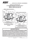
1
OPERATING & MAINTENANCE INSTRUCTIONS
SCOTT ISCBA
INDUSTRIAL SELF-CONTAINED BREATHING APPARATUS
MODEL 2216 ISCBA RESPIRATOR (2216 PSI)
MODEL 4500 ISCBA RESPIRATOR (4500 PSI)
MODEL 2216 ISCBA RESPIRATOR
(2216 PSI)
SHOULDER
STRAPS
REGULATOR
QUICK DISCONNECT
TRI-SLIDE
BUCKLE
CYLINDER
LATCH
OPTIONAL
EBSS HOSE
GAUGE WITH
PROTECTOR
MODEL 4500 ISCBA RESPIRATOR
(4500 PSI)
REGULATOR
QUICK DISCONNECT
SHOULDER
STRAPS
TRI-SLIDE
BUCKLE
CYLINDER
LATCH
OPTIONAL
EBSS HOSE
GAUGE WITH
PROTECTOR
HIP
PADS
HIP
PADS
WAIST BELT
RELEASE
BUCKLE
REGULATOR
HOLDER
PRESSURE REDUCER
HOSE COUPLING (UNATTACHED)
CYLINDER AND
VALVE ASSEMBLY
WAIST BELT
RELEASE
BUCKLE
TYPICAL INDUSTRIAL SCBA 2216 PSI
W/ OPTIONAL ACCESSORIES
For Use With 2216 PSI Cylinders of
30 Minute Rated Duration
REGULATOR
HOLDER
PRESSURE REDUCER
HOSE COUPLING (ATTACHED)
CYLINDER AND
VALVE ASSEMBLY
TYPICAL INDUSTRIAL SCBA 4500 PSI
W/ OPTIONAL ACCESSORIES
For Use With 4500 PSI Cylinders of
30, 45, or 60 Minute Rated Duration
WARNING
IMPROPER USE OF THIS RESPIRATOR MAY RESULT IN SERIOUS INJURY OR DEATH.
IMPROPER USE INCLUDES, BUT IS NOT LIMITED TO, USE WITHOUT ADEQUATE TRAINING,
DISREGARD OF THE WARNINGS AND INSTRUCTIONS CONTAINED HEREIN, AND FAILURE
TO INSPECT AND MAINTAIN THIS RESPIRATOR.
THIS RESPIRATOR IS INTENDED TO BE USED ONLY IN CONJUNCTION WITH AN ORGANIZED
RESPIRATORY PROTECTION PROGRAM WHICH COMPLIES WITH THE REQUIREMENTS OF
“PRACTICES FOR RESPIRATORY PROTECTION”, Z88.2 AVAILABLE FROM AMERICAN NATIONAL STANDARDS INSTITUTE INC., 1430 BROADWAY, NEW YORK, N.Y., 10018, OR THE
REQUIREMENTS OF OSHA SAFETY AND HEALTH STANDARD 29 CFR 1910 PARAGRAPH 134
AVAILABLE FROM THE U.S. DEPARTMENT OF LABOR, OCCUPATIONAL SAFETY AND HEALTH
ADMINISTRATION, OR OTHER PERTINENT NATIONALLY RECOGNIZED STANDARDS.
© 2011 Scott Safety
SCOTT, the SCOTT SAFETY Logo, Scott Health and Safety, ISCBA, AV-2000, AV-3000, SureSeal, Scott-O-Vista, and WeldO-Vista are registered and/or unregistered marks of Scott Technologies, Inc. or its affiliates.
Page 1 of 32
P/N 89332-01 Rev F 7/11
GENERAL DESCRIPTION
The SCOTT Industrial Self-Contained Breathing Apparatus (ISCBA)
is a respirator designed to supply breathable air and respiratory protection to personnel while performing work in objectionable, oxygen
deficient and/or unbreathable (toxic) atmospheres. Model 2216 ISCBA
respirator uses a 2216 psi cylinder while Model 4500 ISCBA respirator uses a 4500 psi cylinder.
This respirator is to be used only by persons trained in the use of
the respirator and only in conjunction with an organized respiratory
protection program. This respirator is not to be used under water, for
interior structural fire fighting or for any other purpose not authorized
by the organized respiratory protection program that applies specifically to the user.
The respirator consists of a cylinder and valve assembly for storing
compressed breathing air, a harness and backframe assembly to support the equipment on the body of the wearer, a single stage pressure
reducer mounted on the backframe, a positive pressure facepiecemounted breathing regulator, and a facepiece assembly.
The pressure reducer has an integral bell alarm to warn the user of
diminishing air supply.
The ISCBA respirator is supplied with a steel wire frame fitted with
a waist strap assembly, shoulder straps, and side straps. The straps
are available either in nylon or flame resistant Kevlar 1 material.
The breathing regulator is equipped with an air saver/donning switch
which can be activated to prevent rapid loss of air supply if the system is turned on prior to donning the facepiece or if the facepiece is
removed while the cylinder valve is open. Respirators are available
with or without a quick disconnect in the hose to the mask-mounted
breathing regulator.
HEAD HARNESS
FACEPIECE
PURGE
VALVE
REMOTE
PRESSURE
GAUGE
BELL
ALARM
SHOULDER
STRAP
BUCKLE
PRESSURE
REDUCER
SIDE RELEASE
BUCKLE
CYLINDER
VALVE
FRONT VIEW
LEFT SIDE VIEW
TYPICAL INDUSTRIAL SCBA
(4500 PSI MODEL SHOWN)
FIGURE 1
1
Kevlar is a registered trademark of E.I. du Pont de Nemours, Inc.
P/N 89332-01 Rev F 7/11
Page 2 of 32
WARNING
THIS RESPIRATOR PROVIDES PROTECTION
O N LY T O T H E U S E R ’ S R E S P I R AT O RY
SYSTEM AND TO PART OF THE FACE.
I F T H E H A Z A R D O U S AT M O S P H E R E
CONTAINS TOXINS OR CONTAMINANTS
WHICH MAY POISON THROUGH THE SKIN,
ADDITIONAL PROTECTIVE EQUIPMENT
MAY BE REQUIRED. FAILURE TO PROVIDE
ADEQUATE PROTECTIVE EQUIPMENT FOR
THE HAZARDS IN THE WORKPLACE MAY
RESULT IN SERIOUS INJURY OR DEATH.
WARNING
DO NOT USE THIS RESPIRATOR FOR FIRE
FIGHTING. USE OF THIS EQUIPMENT FOR
FIRE FIGHTING MAY RESULT IN FAILURE
OF THE EQUIPMENT WHICH COULD CAUSE
SERIOUS INJURY OR DEATH.
BUCKLE
RELEASE
LEVER
AIR SAVER
SWITCH
WARNING
D O N O T O P E R AT E T H I S E Q U I P M E N T
WHILE UNDER THE INFLUENCE OF
DRUGS, ALCOHOL, OR ANY MEDICATIONS
OR SUBSTANCES WHICH MAY AFFECT
VISION, DEXTERITY, OR JUDGMENT. USERS
OF THIS EQUIPMENT MUST BE IN GOOD
PHYSICAL AND MENTAL HEALTH IN ORDER
TO OPERATE SAFELY. DO NOT USE THIS
EQUIPMENT WHEN FATIGUE PREVENTS
SAFE OPERATION. STAY ALERT WHEN
OPERATING THIS EQUIPMENT. INATTENTION
OR CARELESSNESS WHILE OPERATING
THIS EQUIPMENT MAY RESULT IN SERIOUS
INJURY OR DEATH.
WARNING
CERTAIN ENVIRONMENTS MAY REQUIRE
THAT PROTECTIVE MATERIAL COVER SOME
OR ALL OF THE RESPIRATOR IN ADDITION TO
COVERING THE USER. THE USER MUST BE
ABLE TO ACCESS THE CONTROLS OF THE
RESPIRATOR AT ALL TIMES. INABILITY TO
ACCESS CONTROLS OF THE RESPIRATOR
WHEN THE RESPIRATOR IS NEEDED FOR
ESCAPE MAY RESULT IN SERIOUS INJURY
OR DEATH.
The facepiece utilized on this respirator is available in a variety of
sizes and configurations for standard use or special applications. The
facepiece may be readily detached from the breathing regulator to
allow for utilization of the best fitting and most comfortable size facepiece for an individual user. Fit testing per OSHA Standard 29 CFR
Part 1910 or ANSI Standard Z88.2 requires testing in the negative
pressure mode using equipment such as a Portacount Plus 2 Respirator Fit Tester. For this, SCOTT facepieces require use of SCOTT Fit
Test Adapter P/N 804057-01 or equivalent and appropriate negative
pressure testing equipment. Mask Seal Kit P/N 805655-01 may also
be required to attain a proper fit. Head harnesses are available in
several materials including polyester and Kevlar 1. Each size facepiece
may be equipped with a lens kit if the use of corrective spectacles is
required. See ACCESSORIES Section for facepiece options.
The duration of the respirator may be extended by use of a low pressure airline air supply. (For details see ACCESSORIES Section.) The
respirators are National Institute for Occupational Safety and Health
(NIOSH) approved for use in temperatures to -25 °F / -32 °C.
Depending on the cylinder and valve used, the respirators are approved and maintained under NIOSH approval numbers listed on the
NIOSH APPROVAL LABEL. These respirators meet the requirements
of Title 42, Part 84 of the Code of Federal Regulations when used
and maintained in accordance with these instructions and the NIOSH
label located on the harness and backframe assemblies. A complete
NIOSH APPROVAL LABEL is included with these instructions.
For assistance, contact your SCOTT authorized distributor or call
SCOTT Safety at 1-800-247-7257.
WARNING
RESPIRATORS SHALL NOT BE WORN WHEN
CONDITIONS PREVENT A GOOD FACE SEAL.
SUCH CONDITIONS MAY INCLUDE, BUT ARE
NOT LIMITED TO, GROWTH OF BEARDS,
SIDEBURNS, A SKULL CAP THAT PROJECTS
UNDER THE FACEPIECE OR TEMPLE PIECES
ON EYEGLASSES. ALSO, ABSENCE OF ONE
OR BOTH DENTURES CAN SERIOUSLY
AFFECT THE FIT OF A FACEPIECE. ANY
CONDITION WHICH PREVENTS A GOOD
FACE SEAL MAY PERMIT EXPOSURE TO
THE HAZARDOUS ATMOSPHERE WHICH MAY
RESULT IN SERIOUS INJURY OR DEATH.
WARNING
D O N O T U S E T H E B L A C K POLYESTER
HEAD HARNESS OR NYLON BACKFRAME
HARNESS WHEN ACCIDENTAL EXPOSURE
TO HIGH HEAT OR FLAME IS A POSSIBILITY.
I N T H O S E C I R C U M S TA N C E S , T H E
POLYESTER OR NYLON MAY MELT OR BURN
CAUSING INJURY OR MAY INTERFERE WITH
RESPIRATORY PROTECTION RESULTING IN
SERIOUS INJURY OR DEATH.
QUESTIONS OR CONCERNS
If you have any questions or concerns regarding use of this equipment, contact your authorized SCOTT distributor, or contact SCOTT
at 1-800-247-7257 (or 704-291-8300 outside the continental United
States).
EXPORT AND IMPORT
The international transport of this equipment is regulated under United
States export regulations and may be regulated by the import regulations of other countries.
If you have any questions or concerns regarding these regulations,
contact SCOTT at 1-800-247-7257 (or 704-291-8300 outside the
continental United States).
Portacount Plus is a registered trademark of TSI Incorporated
2
Page 3 of 32
P/N 89332-01 Rev F 7/11
FACEPIECE FITTING AND FIT TESTING
A respirator Quantitative Fit Test must be performed to ensure the correct
respirator facepiece size has been selected and assigned to the user. It is
the responsibility of the Respiratory Protection Program Manager or Safety
Coordinator to assist the user in selecting the correct respirator size relative
to the user’s facial features and dimensions. Fit Testing must be performed
with any approved SCOTT accessories that will be used with the respirator
installed, such as a communications device installed on the facepiece.
Respirator fit tests are explained fully in the American National Standard
Practices for Respiratory Protection, ANSI Z88.10-2001 which is published
by the American National Standards Institute (ANSI), 11 West 42nd Street,
New York, New York, 10036, and in the Occupational Safety and Health
Standards, OSHA 29 CFR 1910.134 Appendix A, which is published by the
Occupational Safety and Health Administration (OSHA), 200 Constitution
Avenue, NW, Washington DC, 20210.
Quantitative Fit Testing per OSHA Standard 29 CFR Part 1910.134 Appendix A,
or ANSI Standard Z88.10-2001 requires testing in the negative pressure mode
using equipment such as a Portacount 1 Respirator Fit Tester. For Quantitative
Fit Testing, SCOTT facepieces require use of the appropriate negative pressure testing equipment such as the Portacount Respirator Fit Tester along
with the following:
• SCOTT 40mm facepiece Adapter, P/N 200423-01,
• a new SCOTT P100 Cartridge, P/N 052683,
• SCOTT Probed Fit Test Adapter P/N 805628-01 or equivalent probed
facepieces and the full range of sizes and styles
• Mask Seal Kit, P/N 805655-01
• the appropriate SCOTT communication device and mounting bracket
properly installed on the facepiece, if such an accessory will be used
with the respirator.
• any other optional hood, eyeglass, or other accessory that will be used
with the respirator.
The size and style facepiece must be selected based on the user’s measured
face size. For initial fitting, carefully don the facepiece and conduct a NEGATIVE PRESSURE LEAK TEST according to the instructions provided with the
40mm Adapter. Refer to the DONNING PROCEDURE section of this instruction for the procedure. Follow the DONNING PROCEDURE CAREFULLY. If
the selected facepiece does not pass the NEGATIVE PRESSURE LEAK TEST
or does not fit securely without movement in the chin or chin cup area or the
user experiences discomfort in the chin or throat, try the next nearest size,
larger or smaller. After passing the NEGATIVE PRESSURE LEAK TEST, the
facepiece size selected must be verified by successfully passing a respirator
Quantitative Fit Test.
When fit testing for Open-Circuit, Pressure Demand Self-Contained Breathing
Apparatus and/or Type C Pressure-Demand Supplied Air Respirator mode
of operation (minimum Fit Factor equal to or greater than 500 minimum)
appropriate negative pressure testing equipment must be used. You should
use a P100 Filter, SCOTT P/N 052683 and the SCOTT P/N 805628-01 Fit
Test Adapter.
When using a Portacount Respirator Fit Tester for Quantitative Fit Testing, TSI
recommends that the level of particles in the ambient air must be between
5000 and 30000 particles/cm3. Refer to the Portacount Respirator Fit Tester
user instructions for details including available Particle Generators to use
with the Portacount Respirator Fit Tester if you have difficulty achieving the
minimum level of ambient particle count required.
Test subjects must be in good health at the time of the fit testing. Smoking
or eating less than 30 minutes prior to the test is prohibited. Any and all
conditions that might interfere with a good face to facepiece seal must be
addressed and corrected before performing the fit testing. Refer to the list of
conditions in the DONNING PROCEDURES section of this instruction.
P/N 89332-01 Rev F 7/11
Page 4 of 32
WARNING
THE USER MUST BE PROPERLY FITTED
USING A RESPIRATOR QUANTITATIVE FIT
TEST BEFORE USE AND FOLLOW ALL
WARNINGS AND SPECIAL OR CRITICAL
USER’S INSTRUCTIONS SPECIFIED DURING
USE. FAILURE TO DO SO MAY RESULT IN
SERIOUS INJURY OR DEATH.
WARNING
FIT TESTING IN ACCORDANCE WITH OSHA
STANDARD 29 CFR PART 1910 IS REQUIRED
AS PART OF THE REQUIRED TRAINING
B E F O R E U S E O F T H I S R E S P I R AT O R .
FAILURE TO PROPERLY FIT AND TRAIN
THE USER IN USE OF THE FACEPIECE AND
RESPIRATOR MAY RESULT IN EXPOSURE
TO THE HAZARDOUS ATMOSPHERE WHICH
COULD LEAD TO SERIOUS INJURY OR
DEATH.
WARNING
RESPIRATORS SHALL NOT BE WORN WHEN
C O N D I T I O N S P R E V E N T A G O O D FA C E
SEAL. SUCH CONDITIONS MAY INCLUDE,
BUT ARE NOT LIMITED TO, GROWTH OF
BEARDS, SIDEBURNS, FACIAL HAIR OR LOW
HAIRLINE THAT CROSSES OR INTERFERES
WITH THE SEALING SURFACE, THICK OR
PROTRUDING HAIRSTYLES SUCH AS PONY
TAILS OR BUNS THAT INTERFERE WITH
THE SMOOTH AND CLOSE FIT OF THE HEAD
HARNESS TO THE HEAD, A SKULL CAP
THAT PROJECTS UNDER THE FACEPIECE,
TEMPLE PIECES ON CORRECTIVE EYE
GLASSES, EXCESSIVE USE OF COSMETICS
I N C L U D I N G M O I S T U R I Z E R S , M A K E - U P,
OR AFTER SHAVE, OR ANYTHING ELSE
WHICH INTERFERES WITH THE FACE TO
FACEPIECE SEAL. ALSO, THE ABSENCE OF
ONE OR BOTH DENTURES CAN SERIOUSLY
AFFECT THE FIT OF A FACEPIECE. USE OF
AN IMPROPERLY FITTED FACEPIECE MAY
LEAD TO EXPOSURE TO THE HAZARDOUS
ATMOSPHERE WHICH COULD RESULT IN
SERIOUS INJURY OR DEATH.
To verify the fit factor of the respirator, testing must incorporate an exercise
regimen of normal daily activities. SCOTT requires the following set of fit
test exercises, which are based on OSHA Standard 29 CFR Part 1910.134
Appendix A, and ANSI Z88.10-2001 with modifications.
Exercises are to be performed each for 60 seconds (except as noted) in a
standing position during the test:
• Normal Breathing
• Deep breathing
• Turning head side to side
• Moving head up and down (look up/look down)
• Talking (read the Rainbow Passage)
• Grimace (15 seconds)
• Bending Over (touch toes) / Reach up (toward the ceiling)
• Normal Breathing (repeat)
Fit test exercises must be performed carefully as if the respirator was being used in a hazardous atmosphere. DO NOT bump the facepiece, filter,
or adapter into the body through exaggerated motions. DO NOT talk except
when directed to by the test administrator.
SCOTT requires that users of this respirator with an approved SCOTT facepiece, must achieve a Fit Factor of at least 500 for Type C Pressure-Demand
Supplied Air Respirator mode of operation for use with their assigned facepiece style and size using the fit test procedures and exercise regimen stated
above. If a Fit Factor of at least 500 cannot be achieved with any facepiece
size or style, the user MUST NOT use this respirator.
If the respirator user passes a NEGATIVE PRESSURE LEAK TEST but
DOES NOT pass a respirator Quantitative Fit Test, try the next nearest size,
larger or smaller and repeat the NEGATIVE PRESSURE LEAK TEST and
the Quantitative Fit Test. If leakage is still detected, either per these user
instructions or the OSHA fit testing process, the use of Mask Seal Kit P/N
805655-01 may be required to attain a proper fit. Refer to the INSTALLATION
AND USE INSTRUCTIONS, SCOTT P/N 89462-01, included with the Mask
Seal Kit. After installing the Mask Seal Kit, repeat the fit testing process to
confirm a proper fit.
Once the proper size is selected and assigned to the user following successful Portacount Respirator Fit Tester testing to achieve minimum Fit
Factors required, the respirator user must perform and pass a NEGATIVE
PRESSURE LEAK TEST as described in these instructions every time the
facepiece is donned to ensure proper fit before using the respirator in a
hazardous atmosphere.
During NEGATIVE PRESSURE LEAK TESTING, any facepiece leakage that
is detected from other than the face to facepiece seal may indicate damaged
or defective equipment. Remove the defective equipment from service and
tag for repair by authorized personnel. Repeat the testing with equipment
known to be operating properly.
IF A SATISFACTORY NEGATIVE PRESSURE LEAK TEST CANNOT BE PERFORMED, DO NOT USE THE RESPIRATOR OR ENTER THE HAZARDOUS
ATMOSPHERE.
The facepiece alone does not provide any protection against a hazardous
atmosphere without the use of the complete respirator.
A respirator Quantitative Fit Test must be routinely carried out as outlined
above for each user of this respirator to determine or confirm the amount of
protection that the respirator provides.
Periodically repeating the fit testing is required to identify any physical
changes of the user (such as those listed in the DONNING PROCEDURES)
which could effect the fit of the facepiece.
Page 5 of 32
P/N 89332-01 Rev F 7/11
CHOOSING THE APPROPRIATE EQUIPMENT
Respirators reduce but do not eliminate all exposure to the hazardous atmosphere. Some facepiece/respirator combinations are more effective than
others at reducing exposure depending on the nature and the concentration
of the contaminant in the hazardous atmosphere. When choosing a respirator
and facepiece, the respiratory protection program under which this respirator is to be used must determine the appropriate level of protection that the
facepiece/respirator is expected to provide. Use of inappropriate RESPIRATOR equipment for the work environment may result in exposure to the
hazardous atmosphere which may cause serious injury or death.
The respiratory protection program must also take into consideration the levels
of exposure which may be hazardous irrespective of respiratory protection
(e.g.: contaminants which are toxic through exposure to unprotected skin).
Additional protective equipment such as apparel may be required. However,
any additional protective equipment must not interfere with access to or operation of the respirator.
When properly donned and operated, the SCOTT ISCBA respirator provides
limited protection from airborne contaminants to only the respiratory system
and part of the face of the user. The using agency must provide the appropriate protective clothing for use with the ISCBA respirator and must insure
that protective clothing does not interfere with the operation of the ISCBA
respirator.
NIOSH approval is granted to respiratory protection equipment made up of
specific combinations of parts or assemblies that have been successfully
tested to the performance standards established by the approval agencies.
To maintain NIOSH approval, an AV-3000 facepiece equipped with a SureSeal
face seal P/N 31001738 (Small), P/N 31001739 (Medium), or P/N 31001740
(Large) must be used only with Grey Nose Cup P/N 31001043 (Small), P/N
31001044 (Medium), or P/N 31001045 (Large).
If you are using an AV-3000 facepiece equipped with a SureSeal face seal
and do not have a Grey Nose Cup, contact SCOTT or your authorized SCOTT
distributor. Failure to comply with this requirement will void the approvals for
your respirator. Use of a non-approved configuration in a hazardous atmosphere may result in serious injury or death.
WARNING
THE RESPIRATORY PROTECTION PROGRAM
UNDER WHICH THIS EQUIPMENT IS TO BE
USED MUST DETERMINE THE APPROPRIATE
L E V E L O F P R O T E C T I O N T H AT T H E
RESPIRATOR IS EXPECTED TO PROVIDE.
USE OF INAPPROPRIATE RESPIRATOR
EQUIPMENT FOR THE WORK ENVIRONMENT
M AY R E S U LT I N E X P O S U R E T O T H E
HAZARDOUS ATMOSPHERE WHICH MAY
CAUSE SERIOUS INJURY OR DEATH.
WARNING
THIS RESPIRATOR PROVIDES PROTECTION
O N LY T O T H E U S E R ’ S R E S P I R AT O RY
SYSTEM AND TO PART OF THE FACE.
I F T H E H A Z A R D O U S AT M O S P H E R E
CONTAINS TOXINS OR CONTAMINANTS
WHICH MAY POISON THROUGH THE SKIN,
ADDITIONAL PROTECTIVE EQUIPMENT
MAY BE REQUIRED. FAILURE TO PROVIDE
ADEQUATE PROTECTIVE EQUIPMENT FOR
THE HAZARDS IN THE WORKPLACE MAY
RESULT IN SERIOUS INJURY OR DEATH.
WARNING
TO MAINTAIN NIOSH APPROVAL, AN AV-3000
FACEPIECE EQUIPPED WITH A SURESEAL
FACE SEAL P/N 31001738 (SMALL), P/N
31001739 (MEDIUM), OR P/N 31001740
( L A R G E ) M U S T B E U S E D O N LY W I T H
GREY NOSE CUP P/N 31001043 (SMALL),
P/N 31001044 (MEDIUM), OR P/N 31001045
(LARGE). USE OF A NON-APPROVED
C O N F I G U R AT I O N I N A H A Z A R D O U S
ATMOSPHERE MAY RESULT IN SERIOUS
INJURY OR DEATH.
SERVICE LIFE
The 2216 ISCBA respirator is rated and approved by NIOSH as a 30 minute duration unit and the 4500 ISCBA respirator is rated and approved by
NIOSH as a 30 minute / 45 minute / 60 minute duration unit (depending on
capacity of cylinder used) when properly donned, used and maintained by
trained personnel. A bell alarm a c t u a t e s w h e n a p p r o x i m a t e l y 2 5 % o f
t h e r a t e d s e r v i c e t i m e remains. The alarm will continue to operate
until the cylinder is nearly depleted.
The user should not expect to obtain exactly the rated service life from this
respirator on each use. The work being performed may be more or less
strenuous than that used in the NIOSH test. Where work is more strenuous,
the duration may be shorter, possibly as short as one-half the rated service
time. Likewise, the time remaining after the bell alarm actuates will be similarly reduced.
The duration of the respirator will depend on such factors as:
1. the degree of physical activity of the user;
2. the physical condition of the user;
3. the degree to which the user’s breathing is affected by excitement, fear
or other emotional factors;
4. the degree of training or experience which the user has with this or similar
equipment;
5. whether or not the cylinder is fully charged at the start of the work period;
6. the possible presence in the compressed air of carbon dioxide concentrations greater than .04% normally found in atmospheric air;
7. the atmospheric pressure; for example, if used in a pressurized tunnel
or caisson at 2 atmospheres (15 psi gauge) the duration will be one-half
as long as when used at 1 atmosphere; and at 3 atmospheres will be
one-third as long;
8. loose or improperly fitting facepiece;
9. the condition of the respirator being used.
P/N 89332-01 Rev F 7/11
Page 6 of 32
WARNING
THE RESPIRATOR USER MUST
IMMEDIATELY LEAVE THE AREA
REQUIRING RESPIRATORY PROTECTION
WHEN THE BELL END OF SERVICE
INDICATOR ALARM ACTUATES.
ACTUATION OF THE BELL END OF
SERVICE INDICATOR ALARM WARNS
THAT APPROXIMATELY 25% OF FULL
PRESSURE REMAINS IN THE AIR SUPPLY
CYLINDER (THAT IS, APPROXIMATELY
3/4 OF THE TOTAL AIR SUPPLY HAS
BEEN USED). A DELAY IN LEAVING THE
AREA AFTER ALARM ACTUATION MAY
RESULT IN INJURY OR DEATH.
WARNING
F A I L U R E T O P R O P E R LY F I T T H E
RESPIRATOR FACEPIECE TO THE USER MAY
RESULT IN LITTLE OR NO RESPIRATORY
P R O T E C T I O N A N D M AY E X P O S E T H E
WEARER TO SUBSTANCES WHICH CAN
CAUSE SERIOUS INJURY OR DEATH.
ACCESSORIES
1. Neck Strap, P/N 804088-01, is used to hold facepiece in a ready position.
2. Hard carrying case, P/N 804497-01, and soft carrying case, P/N 10009324,
are used to store and transport respirator.
3. Duration Extending Accessory Hose Assembly is used for the purpose
of extending duration by means of a low pressure airline air supply.
NOTE
ONLY RESPIRATORS EQUIPPED WITH A DUAL OUTLET REDUCER CAN
HAVE THE DURATION EXTENDING ACCESSORY HOSE INSTALLED.
4. A variety of Lens Kits are available to allow installation of corrective
lenses in facepiece.
5. Gauge Protector Kit, P/N 804091-01, provides the remote reading pressure gauge with protection from impact and abrasion.
6. Clear protective Lens Cover, P/N 803941-25 (package of 25), is used
to protect full facepiece lens against external scratching, spatter, paint
spray and abrasion.
7. Nose Cup Assembly, P/N 802819-01, is used to minimize fogging in
the SCOTT-O-VISTA facepiece and is required for use in temperatures
below 32 °F / 0 °C. Nose Cup installation kit, P/N 802862-01, must be
ordered when installing nose cup in the facepiece for the first time. The
installation kit contains the nose cup, adhesive and the required mounting components.
8. Several communications devices are available for use with SCOTT Full
Facepieces with dual voicemitters. Consult with your SCOTT distributor
for details
9. Suit Pass-Thru Assembly, 803620 series, provides a means of delivering
respirable air to specific SCOTT SCBA worn in combination with a
protective garment or suit.
10.Refer to the FACEPIECE FITTING AND FIT TESTING section of this
instruction for information about Fit Testing Accessories. Consult your
SCOTT distributor for details of availability and application.
11. Emergency Breathing Support System (EBSS) allows 2 users of similarly
equipped SCBA’s to share a common air supply in the event one user
has an emergency.
12. Regulator Holder, P/N 10008880, attaches to the waist belt to conveniently
keep the breathing regulator secure and clean when not in use.
13.Facepieces for the respirator are available in a variety of sizes and configurations. Consult with your SCOTT distributor for details about SCOTT
complete line of standard and special purpose full facepieces.
Page 7 of 32
P/N 89332-01 Rev F 7/11
WARNING
THE INFORMATION BELOW IS MEANT TO SUPPLEMENT, NOT REPLACE, THE INSTRUCTIONS, TRAINING, SUPERVISION, MAINTENANCE, AND OTHER ELEMENTS OF YOUR ORGANIZED RESPIRATORY
PROTECTION PROGRAM. SEE WARNING ON PAGE 1 OF THIS DOCUMENT. FAILURE TO HEED ANY
WARNINGS IN THIS INSTRUCTION MAY RESULT IN SERIOUS INJURY OR DEATH.
REGULAR OPERATIONAL INSPECTION
The following procedure shall be used when you first receive the
respirator and for regular inspection of the respirator. Respirators maintained for emergency use must be inspected as frequently as required
to assure the respirator will function properly when required. The US
Labor Department (OSHA), pursuant to 29 CFR 1910.134, requires at
least monthly inspection of respirators maintained for emergency use.
NIOSH recommends an inspection for cylinder pressure at least weekly.
All respirators shall be inspected after each use. If any damage or
malfunction is noted, remove the respirator from service and tag for
repair by authorized personnel.
IF ANY DISCREPANCY OR MALFUNCTION IS NOTED DURING
THE INSPECTION, DO NOT USE THE RESPIRATOR. REMOVE
THE RESPIRATOR FROM SERVICE AND TAG IT FOR REPAIR
BY AUTHORIZED PERSONNEL.
INSPECTION OF THE BREATHING AIR CYLINDER
1. Visually inspect breathing air cylinder and valve assembly for
physical damage such as dents or gouges in metal or in composite
wrapping. Cylinders which show physical damage or exposure to
high heat or flame, such as paint turned brown or black, decals
charred or missing, pressure gauge lens melted or elastomeric
bumper distorted, and cylinders which show evidence of exposure
to chemicals such as discoloration, cracks in the cylinder or the
composite wrapping, peeling of the outer layers of the composite
wrapping and/or bulging of the cylinder wall, shall be removed
from service and emptied of compressed air. Publications on
compressed gas cylinder inspection procedures are available from
Compressed Gas Association Inc., 1725 Jefferson Davis Hwy.,
Suite 1004, Arlington, VA 22202 (703-412-0900).
2. Check the latest cylinder hydrostatic test date to ensure it is current. The date of manufacture marked on the cylinder is also the
date of the first hydrostatic test. All breathing air cylinders used
with SCOTT AIR-PAK SCBA’s must be visually inspected regularly
and hydrostatically tested at the required intervals by a licensed
cylinder retester. Intervals for hydrostatic testing are established in
the appropriate US Department of Transportation (DOT) specification or applicable DOT exemption, or in the appropriate Transport
Canada (TC) Permit of Equivalent Level of Safety. Refer to the
current revision of Safety Precautions for AIR-PAK Cylinders,
SCOTT P/N 89080-01, available on request from SCOTT Safety.
Composite fiber overwrapped cylinders must be tested up to
their maximum life which, at the time of the publication of this
instruction, is 15 years from the date of manufacture. It is the
responsibility of your organized respiratory protection program to
arrange for visual inspection and hydrostatic testing of cylinders
by a licensed retester.
3. Check for damage of the cylinder valve hand wheel and the
threads on the cylinder valve outlet.
4. Check the relief valve (burst disc) for damage or dirt.
5. Check the cylinder pressure gauge for “FULL” indication. If cylinder pressure is less than “FULL,” replace with a fully charged
cylinder.
Proceed to INSPECTION OF THE RESPIRATOR
P/N 89332-01 Rev F 7/11
Page 8 of 32
WARNING
FOLLOW THE REGULAR OPERATIONAL
INSPECTION PROCEDURE EXACTLY. IF
THE END OF SERVICE INDICATOR ALARM
DOES NOT ACTUATE AS DESCRIBED
IN THIS INSTRUCTION, THE PURGE
DOES NOT ACTUATE AS DESCRIBED
IN THIS INSTRUCTION OR ANY OTHER
OPERATIONAL MALFUNCTION IS NOTED,
DO NOT USE THE RESPIRATOR. REMOVE
THE RESPIRATOR FROM SERVICE AND
TAG IT FOR REPAIR BY AUTHORIZED
PERSONNEL. FAILURE TO PROPERLY
IDENTIFY MALFUNCTIONS MAY RESULT
IN SERIOUS INJURY OR DEATH.
WARNING
THE SMALL VENT HOLES IN THE
PRESSURE REDUCER MUST BE CLEAR
AND UNOBSTRUCTED FOR PROPER
O P E R AT I O N O F T H E R E S P I R AT O R .
OBSTRUCTION OF THE VENT HOLES EITHER
BY DIRT ACCUMULATION OR CARELESS
APPLICATION OF USER LABELING MAY
R E S U LT I N A M A L F U N C T I O N O F T H E
R E S P I R ATO R W H I C H C O U L D L E A D TO
SERIOUS INJURY OR DEATH.
WARNING
DAMAGED CYLINDERS MAY SUDDENLY
LEAK OR RUPTURE IF LEFT CHARGED WITH
COMPRESSED AIR. FAILURE TO INSPECT
FOR DAMAGE AND TO EMPTY THE AIR
FROM DAMAGED CYLINDERS MAY RESULT
IN SERIOUS INJURY OR DEATH.
INSPECTION OF THE RESPIRATOR
If any damage is found in this inspection, remove the respirator from
service and tag for repair by authorized personnel.
1. Inspect the complete respirator for worn or damaged components.
a)Inspect hoses and rubber parts which exhibit cracking, splitting,
or brittleness.
b)Inspect harness webbing for cuts, tears, abrasion, fraying, or
indication of heat or chemical damage.
c)Check all buckles and fasteners for proper operation.
d)Check the cylinder retention system for damage and for proper
operation.
e)Verify that the respirator has been properly cleaned.
2. Remove the breathing regulator from the facepiece by pulling
back on the regulator retaining latch and rotating the regulator
¼ turn. Inspect the gasket on the breathing regulator that seals
against the facepiece for rips or damage that may break the
seal.
3. Inspect the breathing regulator for damaged or missing components.
a) Verify that the regulator gasket is not damaged and is in place
around the outlet port of the regulator.
b) Verify that the purge valve (red knob) is not damaged and turns
smoothly one-half turn from stop to stop.
4. If the breathing regulator is equipped with a MODULAIR quick disconnect, SEPARATE the regulator from the respirator by pushing
THE MALE PLUG INTO THE coupling connection WHILE pulling
back on the outer sleeve of the female coupling. The disconnect
will separate. See FIGURE 2.
WARNING
RESPIRATORS MUST BE CLEANED AND
INSPECTED BEFORE STORAGE FOR REUSE.
RESPIRATORS WITH WORN OR DAMAGED
COMPONENTS SHALL NOT BE STORED FOR
REUSE. REPLACE WORN OR DAMAGED
COMPONENTS DURING INSPECTION OR
REMOVE THE RESPIRATOR FROM SERVICE
AND TAG IT FOR REPAIR BY AUTHORIZED
PERSONNEL. USE OF A RESPIRATOR WITH
WORN OR DAMAGED COMPONENTS MAY
RESULT IN SERIOUS INJURY OR DEATH.
CAUTION
DO NOT USE TOOLS TO OPEN OR CLOSE
THE PURGE VALVE. OPEN OR CLOSE BY
USING FINGER-PRESSURE ONLY. ROTATION
OR THE PURGE VALVE IS LIMITED TO 1/2
TURN. USE OF TOOLS TO OPEN OR CLOSE
PURGE VALVE MAY RESULT IN DAMAGE TO
THE PURGE VALVE.
PUSH PLUG IN
PLUG
PULL SLEEVE
BACK
SLEEVE
WARNING
FAILURE TO CHECK ENGAGEMENT OF
THE COUPLING AS DESCRIBED MAY LEAD
TO H O S E S E PA R AT I O N A N D L O S S O F
BREATHING AIR RESULTING IN SERIOUS
INJURY OR DEATH.
FIGURE 2
Reconnect the coupling by pushing the plug into the coupling until
the sleeve snaps forward. Check that the disconnect is engaged
properly by tugging on the coupling.
5. Verify that a FULL cylinder is properly installed in the backframe
and that the reducer hose coupling is hand tightened to the cylinder valve outlet.
Proceed to INSPECTION OF THE FACEPIECE.
REGULAR OPERATIONAL INSPECTION
CONTINUED ON NEXT PAGE...
Page 9 of 32
P/N 89332-01 Rev F 7/11
REGULAR OPERATIONAL INSPECTION Continued...
INSPECTION OF THE FACEPIECE
Examine the facepiece assembly for damaged or worn components.
The facepiece must be complete and in serviceable condition with no
worn, loose, or damaged components.
• The AV-2000 style facepieces include the AV-2000, the Weld-OVista, and the Scott-O-Vista (the Scott-O-Vista does not have
voicemitters).
• The AV-3000 style facepieces include the AV-3000 and the AV3000 SureSeal.
Inspect the facepiece as follows:
1. Inspect the facepiece seal and other rubber components for deformation, wear, damage, or cracks.
2. Inspect the lens for cracks, gouges, scratches, or any condition
that could impair the operation of the facepiece or the user’s
vision.
3. Inspect the lens frame or bezel for damage such as cracks or
distortion.
4. Check that all lens frame retainers or bezel screws are present
and installed correctly.
5. Check that all harness anchors are present and operating properly.
6. Inspect the head harness for correct installation with all straps
oriented correctly.
7. Inspect the head harness for damage or worn components.
8. Inspect the voicemitters for dents or damage. Verify that the
voicemitters are properly installed and secure in the voicemitter
ducts.
9. Inspect the nose cup for cuts or damage. Also look for any signs
of damage to the facepiece port side of the nose cup where the
regulator attaches.
10.Check that the nose cup is properly seated between the flanges
of the voicemitter ducts. See FIGURE 3.
FIGURE 3
Checking Voicemitter Ducts
11.All SCOTT facepieces used with this respirator may be fitted with
a nose cup. Verify that the Nose Cup is properly installed for the
model of facepiece being used. A Nose Cup is standard on the
SCOTT AV-2000, Weld-O-Vista, and AV-3000 full facepieces and
optional on the SCOTT-O-VISTA full facepiece.
a) SCOTT AV-3000 Facepieces are available with two different
styles of nose cup: a BLACK Nose Cup which fits behind the
face seal, and a GRAY Nose Cup which fits in front of the face
seal. The BLACK Nose cup must be fitted BEHIND the Face
Seal as shown in FIGURE 4. The GRAY Nose Cup must be
fitted IN FRONT OF the Face Seal as shown in FIGURE 5.
P/N 89332-01 Rev F 7/11
Page 10 of 32
CAUTION
IF THE NOSE CUP IS REMOVED FOR
I N S P E C T I O N , M A K E C E R TA I N I T I S
R E A S S E M B L E D C O R R E C T LY F O R T H E
MODEL FACEPIECE AND STYLE OF NOSE
CUP.
AV-3000 FACEPIECES ONLY
GRAY
IN FRONT OF
FACE SEAL
BLACK
BEHIND
FACE SEAL
FIGURE 4
FIGURE 5
BLACK Nose Cup
BEHIND Face Seal
GRAY Nose Cup
IN FRONT OF Face Seal
b) The AV-2000, the Weld-O-Vista, and the SCOTT-O-VISTA, the
Nose Cup always goes BEHIND the face seal REGARDLESS
of the color of the nose cup. See FIGURE 6.
AV-2000 FACEPIECES ONLY
WARNING
FAILURE TO CHECK ENGAGEMENT OF
THE COUPLING AS DESCRIBED MAY LEAD
TO H O S E S E PA R AT I O N A N D L O S S O F
BREATHING AIR RESULTING IN SERIOUS
INJURY OR DEATH.
AV-2000 Nose Cup
Always BEHIND the Face Seal
FIGURE 6
12.Verify that the facepiece is clean.
13.Adjust the head straps to the full outward position.
If no damage is found, proceed to the OPERATIONAL TESTING.
CAUTION
W R E N C H E S S H A L L N O T B E U S E D TO
TIGHTEN THE HOSE COUPLING. OVER
TIGHTENING THE HOSE COUPLING MAY
DAMAGE THE NIPPLE SEAL.
OPERATIONAL TESTING
1. Fully depress the center of the air saver/donning switch on the
top of the regulator and release.
2. Slowly open the cylinder valve by fully rotating knob counterclockwise. The bell alarm shall actuate and then stop. There shall be
no airflow from the facepiece
3. Don the facepiece or hold the facepiece to the face to effect a good
seal. Inhale sharply to automatically start the flow of air. Breathe
normally from the facepiece to ensure proper operation.
4 Remove facepiece from face. Air shall freely flow from the
facepiece.
5. Fully depress the center of the air saver/donning switch on the
top of regulator and release. The flow of air from the facepiece
shall stop.
6. Rotate purge valve 1/2 turn counterclockwise (pointer on knob
downward). Air shall freely flow from the regulator.
7. Rotate purge valve 1/2 turn clockwise to full closed position
(pointer on knob upward). Airflow from regulator shall stop.
8. Push in and rotate cylinder valve knob clockwise to close. When
cylinder valve is fully closed, open purge valve slightly to vent
residual air pressure from system. The bell alarm shall actuate
as the pressure drops below approximately 1/4 full. When airflow
stops, return purge valve to the fully closed position (pointer on
knob upward).
Page 11 of 32
CAUTION
DO NOT USE TOOLS TO OPEN OR CLOSE
THE PURGE VALVE. OPEN OR CLOSE BY
USING FINGER-PRESSURE ONLY. ROTATION
OF THE PURGE VALVE IS LIMITED TO 1/2
TURN. USE OF TOOLS TO OPEN OR CLOSE
PURGE VALVE MAY RESULT IN DAMAGE TO
THE PURGE VALVE.
CAUTION
OVERTIGHTENING THE CYLINDER VALVE
MAY CAUSE DAMAGE THAT COULD RESULT
IN LEAKAGE OF AIR FROM THE CYLINDER.
USE NO TOOLS TO CLOSE THE CYLINDER
VALVE.
WARNING
IF THE END OF SERVICE INDICATOR BELL
ALARM DOES NOT ACTUATE AS DESCRIBED
IN THIS INSTRUCTION, DO NOT USE THE
RESPIRATOR. REMOVE THE RESPIRATOR
FROM SERVICE AND TAG IT FOR REPAIR
BY AUTHORIZED PERSONNEL. USE OF AN
IMPROPERLY OPERATING END OF SERVICE
INDICATOR BELL ALARM MAY RESULT IN
SERIOUS INJURY OR DEATH.
P/N 89332-01 Rev F 7/11
USE OF THE RESPIRATOR
The following information provides the basic steps for use of the
ISCBA respirator. Training and practice with the equipment are required before use to assure that the user is completely familiar with
the operation of the respirator.
The ISCBA respirator is typically worn over most protective garments,
but may be worn under encapsulating protective garments such as
haz-mat suits. Determine what other protective gear will be used and
don the ISCBA respirator and the facepiece accordingly.
If respirator use is expected at temperatures near or below freezing,
or if respirator is to be used after being kept at temperatures near or
below freezing, refer to LOW TEMPERATURE OPERATION Section
for additional information and supplemental procedures.
WARNING
THE INFORMATION IN THIS INSTRUCTION IS
MEANT TO SUPPLEMENT, NOT REPLACE, THE
INSTRUCTIONS, TRAINING, SUPERVISION,
MAINTENANCE, AND OTHER ELEMENTS
O F Y O U R O R G A N I Z E D R E S P I R AT O RY
PROTECTION PROGRAM. SEE WARNING
O N PA G E O N E O F T H I S D O C U M E N T.
FAILURE TO HEED ANY WARNINGS IN THIS
INSTRUCTION MAY RESULT IN SERIOUS
INJURY OR DEATH.
PREPARATION FOR USE
DONNING THE ISCBA RESPIRATOR
1. Always check the cylinder gauge for a “FULL” indication. If the cylinder is not full, replace the cylinder before use. A gauge indication
of other than full may indicate an air leak in the cylinder and valve
assembly or a malfunction of the gauge assembly.
2. Always verify that the cylinder is held securely by the cylinder retention assembly.
3. If the respirator is stored in a hard or soft storage case:
a) Place the case on the ground or level surface and open the
case.
b) Stand the respirator on the cylinder valve with cylinder toward you
and the shoulder straps away from you.
c) Grasp both shoulder pads, one in each hand.
d) Pick up the respirator and swing it around behind you.
e) Release your grasp while sliding your arms under the shoulder
pads. Ensure that the shoulder pads fall into place on the shoulders.
f) While leaning slightly forward, pull down on the shoulder straps
to adjust the harness to fit your body.
4. If a wall storage bracket is used, follow the instructions of the bracket
manufacturer for placing arms through shoulder straps and freeing
the respirator from the bracket.
a) Ensure that the shoulder pads fall into place on the shoulders.
b) While leaning slightly forward, pull down on the shoulder straps
to adjust the harness to fit your body.
5. While still leaning slightly forward, connect the waist belt buckle and
adjust the belt by pulling forward on the two (2) side-mounted belt
ends. Tuck the belt ends into the waistband.
6. Stand up straight and readjust the shoulder straps as needed to
ensure the weight of the backframe is carried on the hips. Tuck the
shoulder strap ends under the shoulder straps.
7. Fully depress the center of the air saver/donning switch on top of
regulator and release.
8. If the regulator is not attached to the facepiece, proceed as follows:
a) Verify that the regulator gasket is not damaged and is in place
around the outlet port of the regulator.
b) Align the two flats of the regulator outlet port with the corresponding flats in the facepiece port (the red purge valve on the regulator will be in the 12 o’clock position). Insert the regulator into the
facepiece port.
c) Rotate the regulator counterclockwise (as viewed from inside of
facepiece) until the red purge valve knob is on the left side of the
facepiece. The lock tab on the regulator will lock into the facepiece
retainer with a “click.” When the lock tab is properly engaged, the
regulator will not rotate.
P/N 89332-01 Rev F 7/11
Page 12 of 32
WARNING
B E F O R E E N T E R I N G A P O T E N T I A L LY
HAZARDOUS ATMOSPHERE OR UNKNOWN
CONDITION, THE USER MUST DETERMINE
THAT THE CYLINDER CONTAINS SUFFICIENT
AIR TO ALLOW TIME FOR COMPLETION OF
THE TASK INVOLVED AND RETURN TO A
SAFE ATMOSPHERE WITH AN ADEQUATE
MARGIN FOR SAFETY. THE USER SHOULD
A LWAY S S TA R T W I T H A F U L L TA N K .
PARTIALLY FILLED TANKS SHOULD ONLY
BE USED IN EMERGENCY CONDITIONS
I F F U L L TA N K S A R E N O T AVA I L A B L E .
ENTERING A HAZARDOUS ATMOSPHERE
WITH INSUFFICIENT AIR OR AFTER THE
END OF SERVICE TIME INDICATOR HAS
A C T U AT E D M AY R E S U LT I N S E R I O U S
INJURY OR DEATH.
WARNING
FAILURE TO CHECK ENGAGEMENT OF
THE COUPLING AS DESCRIBED MAY LEAD
TO H O S E S E PA R AT I O N A N D L O S S O F
BREATHING AIR RESULTING IN SERIOUS
INJURY OR DEATH.
WARNING
THE CYLINDER VALVE MUST BE FULLY
OPENED FOR PROPER OPERATION OF THE
RESPIRATOR. USE OF A RESPIRATOR WITH
THE CYLINDER VALVE PARTIALLY OPENED
MAY CAUSE A REDUCTION OF THE AIR
SUPPLIED TO THE USER AND/OR A SUDDEN
AND COMPLETE LOSS OF AIR SUPPLIED TO
THE USER. A REDUCTION OR LOSS OF AIR
TO THE USER MAY RESULT IN EXPOSING
T H E U S E R TO T H E AT M O S P H E R E T H E
RESPIRATOR IS INTENDED TO PROTECT
AGAINST AND LEAD TO SERIOUS INJURY
OR DEATH.
CHECK THE OPERATION OF THE ISCBA RESPIRATOR
1. Slowly open cylinder valve fully by turning the valve knob counterclockwise until it stops (approximately 2 1/2 full turns of the knob).
The bell alarm shall actuate and then stop. There shall be no airflow
from the facepiece
2. Don the facepiece or hold the facepiece to the face to effect a good
seal. Inhale sharply to automatically start the flow of air. Breathe
normally from the facepiece to ensure proper operation.
3 Remove facepiece from face. Air shall freely flow from the facepiece.
4. Fully depress the center of the air saver/donning switch on the top of
regulator and release. The flow of air from the facepiece shall stop.
5. Rotate purge valve 1/2 turn counterclockwise (pointer on knob downward). Air shall freely flow from the regulator.
6. Rotate purge valve 1/2 turn clockwise to full closed position (pointer
on knob upward). Airflow from regulator shall stop.
7. Push in and rotate cylinder valve knob clockwise to close. When cylinder valve is fully closed, open purge valve slightly to vent residual
air pressure from system. The bell alarm shall actuate as the pressure
drops below approximately 1/4 full. When airflow stops, return purge
valve to the fully closed position (pointer on knob upward).
8. The user of the respirator is now in “standby” condition. The respirator is in place on the user’s body but the facepiece is not donned
(sealed to the face) and the respirator is not being used. Keep the
facepiece ready for use either of two ways:
a) Hang the facepiece from the snap clip on the left shoulder pad,
b) Hang the facepiece from the optional neck strap.
9. The regulator can be detached from the facepiece until needed. To
detach the regulator from the facepiece:
a) Place your right hand over the cover with your thumb on the lock
tab.
b) Pull the lock tab toward the cover and rotate the regulator 1/4 turn
clockwise (viewed from inside of facepiece).
c) When the red purge valve is in the 12 o’clock position remove
regulator from the facepiece.
d) The regulator can be stored in the optional regulator holder on the
waist belt.
Proceed to the FACEPIECE DONNING PROCEDURES section of this
instruction.
WARNING
IF THE END OF SERVICE INDICATOR BELL
ALARM DOES NOT ACTUATE AS DESCRIBED
IN THIS INSTRUCTION, DO NOT USE THE
RESPIRATOR. REMOVE THE RESPIRATOR
FROM SERVICE AND TAG IT FOR REPAIR
BY AUTHORIZED PERSONNEL. USE OF AN
IMPROPERLY OPERATING END OF SERVICE
INDICATOR BELL ALARM MAY RESULT IN
SERIOUS INJURY OR DEATH.
CAUTION
OVERTIGHTENING THE CYLINDER VALVE
MAY CAUSE DAMAGE THAT COULD RESULT
IN LEAKAGE OF AIR FROM THE CYLINDER.
USE NO TOOLS TO CLOSE THE CYLINDER
VALVE.
USE OF RESPIRATOR
CONTINUED ON NEXT PAGE...
Page 13 of 32
P/N 89332-01 Rev F 7/11
USE OF RESPIRATOR CONTINUED...
FACEPIECE DONNING PROCEDURES
Before use of the respirator, the user must read and practice the
procedures for donning, use, and termination of use. The user must
be familiar with and practice the prescribed donning, leak test, use,
and termination of use procedures prior to respirator use. Follow the
donning instructions for the model facepiece you have.
The DONNING INSTRUCTIONS for FOUR STRAP full facepieces
(such as the AV-2000, AV-3000, Scott-O-Vista, and the Weld-O-Vista)
and the FIVE STRAP full facepieces (such as the AV-3000 SureSeal)
are included in this instruction.
The respirator MUST NOT be worn when conditions prevent a good
face to facepiece seal. Such conditions include but are not limited
to:
•
long hair at the forehead or the side of the face that interferes with
the sealing surface or gets caught in the head harness buckles,
•
facial hair such as growth of beard or sideburns, or low hairline
that crosses or interferes with the sealing surface,
•
thick or protruding hairstyles such as pony tails or buns that interfere with the smooth and close fit of the head harness to the
head,
•
temple pieces on corrective glasses,
•
a skull cap that projects under the facepiece,
•
excessive use of cosmetics including moisturizers, make-up, or
after shave,
•
the absence of one or both dentures,
•
weight loss or weight gain since last fit testing,
•
facial scarring,
•
anything else which interferes with the face to facepiece seal or
the fit of the head harness to the head.
Periodically repeating the fit testing is required to identify any physical
changes of the user (such as those listed above) which could affect
the fit of the facepiece.
NOTE
IF THE STYLE FULL FACEPIECE RESPIRATOR MASK IS BEING DONNED
FOR THE FIRST TIME OR IF THIS IS THE FIRST TIME A PARTICULAR
STYLE FACEPIECE IS TO BE USED, REFER TO THE APPROPRIATE
STEPS IN THE FACEPIECE FITTING SECTION OF THIS INSTRUCTION.
DURING TRAINING, THE USER MUST DETERMINE THE LEVEL OF TIGHTNESS OF THE HEAD HARNESS REQUIRED TO PROVIDE THE BEST SEAL
AND MOST SECURE FIT.
If the facepiece is to be used with a hood, refer to the donning instructions provided with the hood. For other head gear that will cover the
facepiece head harness and/or hood, don the facepiece/hood first,
then don the other head gear.
To don the facepiece and begin use of respirator, proceed as
follows:
P/N 89332-01 Rev F 7/11
Page 14 of 32
WARNING
RESPIRATORS SHALL NOT BE WORN WHEN
CONDITIONS PREVENT A GOOD FACE SEAL.
SUCH CONDITIONS MAY INCLUDE, BUT ARE
NOT LIMITED TO, GROWTH OF BEARDS,
S I D E B U R N S , FA C I A L H A I R O R L O W
HAIRLINE THAT CROSSES OR INTERFERES
WITH THE SEALING SURFACE, THICK OR
PROTRUDING HAIRSTYLES SUCH AS PONY
TAILS OR BUNS THAT INTERFERE WITH THE
SMOOTH AND CLOSE FIT OF THE HEAD
HARNESS TO THE HEAD, A SKULL CAP
THAT PROJECTS UNDER THE FACEPIECE,
TEMPLE PIECES ON CORRECTIVE EYE
GLASSES, EXCESSIVE USE OF COSMETICS
I N C L U D I N G M O I S T U R I Z E R S , M A K E - U P,
OR AFTER SHAVE, OR ANYTHING ELSE
WHICH INTERFERES WITH THE FACE TO
FACEPIECE SEAL. ALSO, THE ABSENCE OF
ONE OR BOTH DENTURES CAN SERIOUSLY
AFFECT THE FIT OF A FACEPIECE. USE OF
AN IMPROPERLY FITTED FACEPIECE MAY
LEAD TO EXPOSURE TO THE HAZARDOUS
ATMOSPHERE WHICH COULD RESULT IN
SERIOUS INJURY OR DEATH.
DONNING THE FOUR STRAP FACEPIECE
(including: AV-2000, AV-3000, Scott-O-Vista, and Weld-OVista)
1. Adjust the head straps to their full outward position.
2. Hold the facepiece in one hand and hold the head harness by the
strap at the base of the head net.
3. Place the facepiece on the face with chin properly located in the
chin pocket while pulling the head harness over the top of the
head. Verify that no hair or clothing is interfering with the face to
facepiece seal. See FIGURE 7-A.
4. Tighten the neck straps by pulling the two lower strap ends toward
the rear of the head. See FIGURE 7-B.
5. Stroke the head harness net down the back of the head using one
or both hands. Verify that the head harness is lying flat against
the back of the head. Retighten the neck straps. See FIGURE
7-C.
7-A
7-C
7-B
NOTE
ENSURE THAT THE CHIN IS PROPERLY
LOCATED IN THE CHIN POCKET OF
THE FACEPIECE THROUGHOUT THE
DONNING PROCESS.
WARNING
FAILURE TO DON THE FACEPIECE AND/OR
FAILURE TO ADJUST THE HEAD HARNESS
AS DESCRIBED IN THIS INSTRUCTION MAY
RESULT IN A POOR FACE TO FACEPIECE
SEAL OR MAY RESULT IN THE FAILURE OF
THE FACE TO FACEPIECE SEAL DURING USE.
A POOR OR FAILED FACE TO FACEPIECE
SEAL MAY REDUCE THE DURATION OF
USE OF THE RESPIRATOR AND/OR EXPOSE
T H E U S E R TO T H E AT M O S P H E R E T H E
RESPIRATOR IS INTENDED TO PROTECT
AGAINST RESULTING IN SERIOUS INJURY
OR DEATH.
7-D
FIGURE 19
DONNING THE FOUR STRAP FACEPIECE
NOTE
VERIFY THAT THE TOP CENTER PORTION OF THE HEAD HARNESS IS
POSITIONED OVER THE CROWN OF
THE HEAD.
6. Tighten the two temple straps. Adjust the temple straps by pulling
the two temple strap ends toward the back of the head. Overtightening may cause discomfort. See FIGURE 7-D.
7. Retighten the neck straps if required.
8. Refer to the DONNING PROBLEMS section of this instruction.
USE OF THE RESPIRATOR
CONTINUED ON NEXT PAGE...
Page 15 of 32
P/N 89332-01 Rev F 7/11
USE OF RESPIRATOR CONTINUED...
DONNING THE FIVE STRAP AV-3000 SURESEAL FACEPIECE
1. Adjust the head straps to the full outward position.
FIGURE 8-A
ADJUST HEAD STRAPS OUT
2. Hold the facepiece in one hand while holding the head harness
up and out of the way with other hand. If so equipped, use the
Head Harness Pull Tab on the bottom rear of the head harness
FIGURE 8-B
HARNESS OUT OF WAY
3. Place the facepiece centered on the face with the chin properly
positioned in the chin cup. Verify that no hair or clothing is interfering with the face to facepiece seal. Hold the facepiece in
place with the chin properly located in the chin cup throughout
the donning process.
NOTE
ENSURE THAT THE CHIN IS PROPERLY
LOCATED IN THE CHIN POCKET OF
THE FACEPIECE THROUGHOUT THE
DONNING PROCESS.
FIGURE 8-C
CHIN IN CHIN POCKET
4. Stroke the head harness over the head and ensure that straps are
lying smooth and flat against the head and neck with no twists.
Verify the head harness is centered and properly located at the
back and base of the head. Maintain the head harness in this
position.
NOTE
VERIFY THAT THE TOP CENTER PORTION OF THE HEAD HARNESS IS
POSITIONED OVER THE CROWN OF
THE HEAD.
FIGURE 8-D
HEAD HARNESS POSITION
P/N 89332-01 Rev F 7/11
Page 16 of 32
5. While holding the facepiece in place with one hand, tighten the
neck straps evenly one at a time by pulling each neck strap end
toward the rear of the head. Alternate hands to maintain the facepiece position on the face.
FIGURE 8-E
HOLD AND TIGHTEN
6. Verify the proper location of the face in the facepiece and the
chin in the chin cup. While still holding the facepiece in place with
one hand, tighten the temple straps evenly one at a time by pulling each temple strap end toward the rear of the head. Alternate
hands to maintain the facepiece position on the face.
FIGURE 8-F
HOLD AND TIGHTEN
7. Verify the proper location of the face in the facepiece and the
chin in the chin cup. Tighten the forehead strap last by pulling the
forehead strap toward the back of the head. Do not overtighten
the forehead strap.
FIGURE 8-G
TIGHTEN FOREHEAD STRAP
8. Verify that the head harness is centered on the crown of the head
and lying flat against the back of the head. Verify the proper location of the face in the facepiece and the chin in the chin cup and
retighten all straps as needed.
NOTE
ENSURE THAT THE CHIN IS PROPERLY
LOCATED IN THE CHIN POCKET OF
THE FACEPIECE THROUGHOUT THE
DONNING PROCESS.
FIGURE 8-H
HEAD HARNESS
MUST BE FLAT AND CENTERED
USE OF RESPIRATOR
CONTINUED ON NEXT PAGE...
Page 17 of 32
P/N 89332-01 Rev F 7/11
USE OF RESPIRATOR CONTINUED...
9. Stroke the head harness down the back of the head and make
sure the net is centered on your head. If necessary, adjust the
head harness net to the center of the crown of the head.
NOTE
VERIFY THAT THE TOP CENTER PORTION OF THE HEAD HARNESS IS
POSITIONED OVER THE CROWN OF
THE HEAD.
CENTER HEAD HARNESS ON THE CROWN OF THE HEAD
FIGURE 8-I
10.Verify the proper location of the face in the facepiece and the chin
in the chin cup. Retighten the straps if required. All straps must
be snug and the facepiece should feel secure.
NOTE
VERIFY THAT THE TOP CENTER PORTION OF THE HEAD HARNESS IS
POSITIONED OVER THE CROWN OF
THE HEAD.
FIGURE 8-J
RETIGHTEN IF REQUIRED
11.Refer to the DONNING PROBLEMS section of this instruction.
P/N 89332-01 Rev F 7/11
Page 18 of 32
DONNING PROBLEMS
1. Perform a personal check of the Facepiece and Head Harness
and address any donning problems. OSHA standard 29 CFR
1910.134 requires teams of at least two people for situations
where this type of equipment is used. Have your partner help
you verify the facepiece is donned properly.
Possible problems include:
a)Head Harness Strap twisted,
b)Head Harness off-center or not flat against the head,
c)Head Harness too high on the head,
d)Hair or clothing in the face seal,
e)Face seal rolled over inside the facepiece rather than flat
against the face
f) Facepiece is sitting too low on the face as evidenced by pressure on the forehead or the facepiece making contact with the
throat area permitting a break in the seal.
The illustrations below depict the AV-3000 SureSeal, but similar
conditions can occur with the AV-2000 or AV-3000 facepiece as
well.
HARNESS STRAP
TWISTED
HEAD HARNESS
OFF CENTER
WARNING
IF ANY DONNING PROBLEMS ARE
FOUND, REMOVE THE FACEPIECE AND
R E - D O N I T C O R R E C T LY. U S E O F A N
IMPROPERLY DONNED FACEPIECE MAY
LEAD TO EXPOSURE TO THE HAZARDOUS
ATMOSPHERE WHICH COULD RESULT IN
SERIOUS INJURY OR DEATH.
HEAD HARNESS
TOO HIGH
FACE SEAL
FACEPIECE
ROLLED OVER
TOO LOW
FIGURE 9
DONNING PROBLEMS
If any donning problems are found, remove the facepiece and
re-don the facepiece correctly.
2. Proceed to BEGIN USE OF THE RESPIRATOR as instructed
below.
USE OF RESPIRATOR
CONTINUED ON NEXT PAGE...
Page 19 of 32
P/N 89332-01 Rev F 7/11
BEGIN USE OF THE RESPIRATOR
1. If regulator is not attached to facepiece, be sure the regulator
gasket is in place around the outlet port of the regulator and not
damaged.
2. To attach the regulator to the facepiece, hold the regulator with
the red purge valve in the 12 o’clock position, align the two flats
of the outlet port with corresponding flats in the facepiece port
and insert. Rotate the regulator counterclockwise (viewed from
inside of facepiece) so that the red purge valve knob is situated on
the left side of the facepiece. The lock tab on the mask-mounted
regulator will lock into the facepiece retainer with a “click”. When
properly engaged, the regulator will not rotate.
With facepiece sealed to face, inhale sharply to actuate respirator.
Air will then be supplied during inhalation.
NOTE
IF AIR IS NOT SUPPLIED ON FIRST INHALATION, CHECK THAT
CYLINDER VALVE IS OPEN, REMOTE GAUGE INDICATES PRESSURE IN CYLINDER AND FACEPIECE IS SEALED TO FACE.
3. NEGATIVE PRESSURE LEAK TEST – Close cylinder valve by
simultaneously pushing in on cylinder valve knob and rotating it
clockwise. Breathe on respirator until airflow stops. The bell alarm
will actuate, then stop. Inhale slowly and hold your breath momentarily. No leakage of air shall be detected and the facepiece
shall be drawn slightly to the face. Open cylinder valve fully and
breathe normally.
4. If the environment is suitably quiet, leakage from the facepiece
can also be detected by listening for a flow of air while holding
your breath. Inhale and hold your breath momentarily after donning the facepiece. Do not depress air saver switch. Air should
not be heard flowing into the facepiece from the regulator and no
flow of air shall be detected outward from the facepiece.
NOTE
IF LEAKAGE OF AIR IS DETECTED DURING EITHER OF THE
ABOVE PROCEDURES, DEPRESS THE AIR SAVER/DONNING
SWITCH ON THE TOP OF THE REGULATOR, DOFF THE FACEPIECE AND REPEAT DONNING STEPS 1 THROUGH 8 ABOVE.
IF LEAKAGE PERSISTS, DO NOT USE THE RESPIRATOR.
5. Proceed with use of respirator in accordance with your respiratory
protection program.
EVERY ENTRY INTO A CONTAMINATED OR UNKNOWN ATMOSPHERE SHOULD BE PLANNED TO ENSURE THAT THERE IS
SUFFICIENT AIR SUPPLY TO ENTER, CARRY OUT THE TASKS
REQUIRED AND RETURN TO A SAFE BREATHING AREA. THE
USER SHOULD CHECK THE REMOTE READING PRESSURE
GAUGE ON THE SHOULDER STRAP PERIODICALLY TO DETERMINE THE RATE OF AIR CONSUMPTION. IN ANY EVENT,
THE USER MUST BE CERTAIN TO ALLOW SUFFICIENT AIR
FOR EGRESS FROM THE CONTAMINATED AREA. IF ENTRY
IS ATTEMPTED AFTER THE AIR HAS BEEN PARTIALLY CONSUMED (CYLINDER LESS THAN FULL), THE USER MUST BE
CERTAIN THAT THE REMAINING AIR WILL BE SUFFICIENT FOR
SAFETY.
Leave the contaminated or unknown atmosphere immediately
if the bell alarm actuates and, in a safe area, determine cause
of alarm. When air supply has been depleted, replace cylinder
following CYLINDER REPLACEMENT PROCEDURE.
P/N 89332-01 Rev F 7/11
Page 20 of 32
WARNING
WHEN THE BELL ALARM ACTUATES IT
WARNS THE USER THAT APPROXIMATELY
25% OF THE FULL PRESSURE REMAINS IN
THE CYLINDER (THAT IS, APPROXIMATELY
3 / 4 O F T H E T O TA L A I R S U P P LY H A S
BEEN USED). IN THIS EVENT, LEAVE THE
CONTAMINATED AREA AT ONCE. IN AREAS
WHERE MORE THAN ONE RESPIRATOR IS
BEING USED, YOU MAY IDENTIFY YOUR
OWN ALARM BY SENSING THE VIBRATIONS
THROUGH YOUR BACKFRAME.
TERMINATION OF USE
To doff the facepiece (i.e., remove the facepiece and terminate respiratory protection), proceed as follows:
1. Leave contaminated area or be certain that respiratory protection
is no longer required. Decontamination may be required by your
respiratory protection program.
2. Loosen the neck straps by simultaneously lifting the lower buckle
release levers outward (away from the head) and lifting facepiece
away from face. The buckle release levers are the “U-shaped”
extensions of the facepiece buckle assemblies.
NOTE
THE USER MAY FIND IT MORE COMFORTABLE TO FIRST RELIEVE TENSION ON THE UPPER STRAP BY LIFTING THE UPPER
BUCKLE RELEASE LEVERS.
3. To stop the flow of air from the facepiece, fully depress the air
saver/donning switch on top of the regulator and release.
NOTE
OPERATION OF THE AIR SAVER/DONNING SWITCH IS INTENDED TO
PREVENT A FREE FLOW OF AIR AND THE DEPLETION OF THE AIR
SUPPLY WHEN THE FACEPIECE IS DOFFED. WITH THE AIR SAVER/
DONNING SWITCH ACTIVATED, THE PURGE VALVE AND BELL
ALARM WILL FUNCTION NORMALLY. IF THE PURGE VALVE HAS
BEEN ADJUSTED TO PRODUCE A FLOW, OR IF THE BELL ALARM
IS IN OPERATION, THE AIR WILL CONTINUE TO BE DEPLETED.
4. Remove the facepiece by pulling it up and over the head.
NOTE
IF THE RESPIRATOR IS NOT GOING TO BE USED FOR A PERIOD OF TIME, CLOSE THE CYLINDER VALVE.
5. To resume use of the respirator, repeat the facepiece donning
procedure (see USE OF RESPIRATOR Section).
6. When respirator operations are completed and only when in a
safe breathing area, check that the cylinder valve is closed, and
vent the residual air from the respirator by opening the purge
valve. After waiting until the air flow stops, close the purge valve.
Loosen shoulder straps by depressing the thumb tabs on ends of
shoulder strap buckles and release waist belt by either simultaneously squeezing top and bottom releases if equipped with a side
release waist belt buckle or depressing center button if equipped
with center release buckle. Remove the unit from your back.
Proceed in accordance with the requirements of your respiratory
protection program for service of the respirator. The respiratory
protection program should include procedures for replacement
of the cylinder with a fully charged cylinder (see CYLINDER
REPLACEMENT Section) and for carrying out the instructions in
STANDBY INSPECTION, CLEANING AND STORAGE section for
respirator and accessories.
CAUTION
FAILURE TO RELEASE TENSION ON NECK
STRAPS BEFORE REMOVING FACEPIECE
M AY C A U S E P R E M AT U R E W E A R O R
DAMAGE TO STRAPS AND/OR FACEPIECE
ASSEMBLY.
WARNING
I F A I R F L O W F R O M T H E R E G U L AT O R
CANNOT BE STOPPED BY DEPRESSING THE
AIR SAVER/DONNING SWITCH, IMMEDIATELY
CLOSE THE CYLINDER VALVE TO PREVENT
DEPLETION OF THE AIR REMAINING IN
THE CYLINDER. LOSS OF BREATHING AIR
MAY RESULT IN REDUCED DURATION OF
THE RESPIRATOR WHICH COULD LEAD TO
SERIOUS INJURY OR DEATH.
WARNING
DO NOT ALLOW RESPIRATOR TO DROP
FROM BODY WHEN REMOVING. DROPPING
OF THE RESPIRATOR MAY CAUSE DAMAGE
TO THE RESPIRATOR THAT MAY LEAD TO
A MALFUNCTION WHICH COULD RESULT IN
INJURY OR DEATH.
WARNING
IF RESPIRATOR USE IS RESUMED AFTER
THE AIR HAS BEEN PARTIALLY CONSUMED
(CYLINDER LESS THAN FULL), YOU MUST BE
CERTAIN THAT THE REMAINING AIR WILL BE
SUFFICIENT FOR YOUR SAFETY. (SEE STEP
13 IN USE OF RESPIRATOR SECTION.) USE
OF A RESPIRATOR WITHOUT A SUFFICIENT
SUPPLY OF BREATHING AIR MAY RESULT
IN SUDDEN TERMINATION OF BREATHING
AIR RESULTING IN SERIOUS INJURY OR
DEATH.
CAUTION
OVERTIGHTENING THE CYLINDER VALVE
MAY CAUSE DAMAGE THAT COULD RESULT
IN LEAKAGE OF AIR FROM THE CYLINDER.
USE NO TOOLS TO CLOSE THE CYLINDER
VALVE.
CAUTION
FAILURE TO RELEASE TENSION ON
SHOULDER STRAPS BEFORE REMOVING
RESPIRATOR MAY CAUSE PREMATURE
WEAR OR DAMAGE TO STRAPS AND/OR
RESPIRATOR ASSEMBLY.
CAUTION
DO NOT LEAVE THE CYLINDER VALVE
OPEN WHEN THE RESPIRATOR IS NOT
IN USE. OVER TIME, THE CYLINDER MAY
LOSE PRESSURE AND HAVE INSUFFICIENT
BREATHING AIR WHEN NEEDED.
Page 21 of 32
P/N 89332-01 Rev F 7/11
EMERGENCY OPERATION
The respirator is automatic in function requiring only the opening of
the cylinder valve and the proper donning of the facepiece to place
into use and the closing of the cylinder valve at the end of use. In
the event of a malfunction or a suspected malfunction, implement the
appropriate emergency procedure listed below:
1. Should the bell alarm actuate during use, and before the air supply is depleted to approximately 25% of full capacity, the reducer
may have failed. LEAVE THE CONTAMINATED AREA AT ONCE
ON ACTUATION OF BELL ALARM.
2. Should the air supply be partially or completely cut off during use,
or if you are unable to start the flow of air automatically, fully open
the purge valve (red knob on regulator) by turning it counterclockwise, (pointer on knob downward). LEAVE THE CONTAMINATED
AREA AT ONCE AFTER OPENING THE PURGE VALVE.
3. Should the air supply begin to flow freely into facepiece, fully open
the purge valve (red knob on regulator) by turning it counterclockwise (pointer on knob downward), partially close the cylinder valve
by pushing in and rotating clockwise to regulate the flow of air
to satisfy the requirements of the user. Do not close the cylinder
valve completely. LEAVE THE CONTAMINATED AREA AT ONCE
AFTER PARTIALLY CLOSING CYLINDER VALVE.
4. In the unlikely event of the blockage of air flow or sudden
and complete loss of the system air supply such that there is
total irreversible loss of respiratory protection, LEAVE THE
CONTAMINATED AREA AT ONCE USING ALL PRECAUTIONS
AND FOLLOW EMERGENCY PROCEDURES PRESCRIBED
BY USER ESTABLISHED RESPIRATORY PROTECTION
PROGRAM.
If the above procedures are implemented during use, REMOVE
THE RESPIRATOR IN A SAFE AREA, tag the respirator and hold
it for service and repair by Authorized Personnel.
P/N 89332-01 Rev F 7/11
Page 22 of 32
WARNING
T H E S E E M E R G E N C Y O P E R AT I O N
PROCEDURES ARE FOR EMERGENCY USE
ONLY. THEY ARE MEANT TO SUPPLEMENT,
NOT REPLACE, THE EMERGENCY
PROCEDURES PRESCRIBED BY YOUR
RESPIRATORY PROTECTION PROGRAM.
IF ANY OF THESE PROCEDURES MUST
BE USED, LEAVE THE CONTAMINATED
A R E A I M M E D I AT E LY. U S E O F T H E S E
PROCEDURES WILL INCREASE THE RATE OF
CONSUMPTION OF THE AIR SUPPLY WHICH
MAY RESULT IN SUDDEN TERMINATION OF
AIR SUPPLY WHICH MAY CAUSE SERIOUS
INJURY OR DEATH.
WARNING
THE AIRFLOW THROUGH THE RESPIRATOR
WHEN THE PURGE VALVE IS OPEN CAN
EXCEED 200 LITERS PER MINUTE. WHEN
USING EMERGENCY PROCEDURE #2, THE
AIR SUPPLY MAY BE CONSERVED AND
THE AIRFLOW REDUCED BY PARTIALLY
CLOSING THE PURGE VALVE. FAILURE TO
LEAVE THE CONTAMINATED AREA AFTER
THE PURGE VALVE HAS BEEN OPENED MAY
RESULT IN SUDDEN TERMINATION OF AIR
SUPPLY LEADING TO SERIOUS INJURY OR
DEATH.
WARNING
EMERGENCY PROCEDURE #3 IS THE ONLY
TIME THE RESPIRATOR MAY BE OPERATED
WITH THE CYLINDER VALVE LESS THAN
FULLY OPENED. FAILURE TO LEAVE THE
CONTAMINATED AREA AFTER THE PURGE
VALVE HAS BEEN OPENED OR COMPLETE
CLOSURE OF THE CYLINDER VALVE MAY
RESULT IN SUDDEN TERMINATION OF AIR
SUPPLY LEADING TO SERIOUS INJURY OR
DEATH.
LOW TEMPERATURE OPERATION
The respirator is NIOSH approved for use in temperatures to –25 °F
/ –32 °C. For temperatures below 32 °F / 0 °C, approval requires use
of a Nose cup Assembly.
Respirators intended for routine use and respirators not routinely
used but kept for emergency use should be located in areas where
the temperature is maintained above freezing (32 °F / 0 °C). Where
it is expected that the respirator will be used in ambient temperatures
near or below freezing, the respirator shall be equipped with a Nose
cup Assembly to reduce the formation of vision impairing mist or ice
on the interior of the facepiece vision area. A Nose cup Assembly
may be added to the SCOTT-O-VISTA full facepieces.
If a respirator may be unavoidably kept at a temperature below freezing before the next use, special care MUST be exercised to be certain
that all components of the respirator are THOROUGHLY DRIED after cleaning and before storage. Whenever use of the respirator is
anticipated in areas at or below freezing, the facepiece, regulator,
and connection hoses MUST be protected against exposure to water
during storage.
If a respirator must be kept at a temperature below freezing and it is
not possible to bring it to room temperature before it is used, do not
exhale into the facepiece until the facepiece is completely donned
and properly fitted against the face.
Page 23 of 32
WARNING
U S E O F T H I S R E S P I R AT O R I N
TEMPERATURES AT OR BELOW FREEZING,
32° F / 0° C, WITHOUT FOLLOWING THE LOW
TEMPERATURE OPERATION INSTRUCTIONS
MAY RESULT IN OBSCURED VISION DUE TO
FOGGING AND/OR PARTIAL OR COMPLETE
BLOCKAGE OF THE AIRFLOW. IF THIS
SHOULD OCCUR, THE AIR SUPPLY MAY BE
PARTIALLY OR COMPLETELY CUT OFF AND/
OR IT MAY BE DIFFICULT OR IMPOSSIBLE
TO SEE THROUGH THE FACEPIECE LENS
WHICH COULD RESULT IN SERIOUS INJURY
OR DEATH.
WARNING
THE RESPIRATOR MUST BE COMPLETELY
D RY B E F O R E A N D D U R I N G S TO R A G E .
MOISTURE IN THE FACEPIECE OR THE
WORKING PARTS OF THE RESPIRATOR,
ESPECIALLY WHEN EXPOSED TO FREEZING
TEMPERATURES, MAY CAUSE FOGGING OF
THE FACEPIECE OR A MALFUNCTION OF
THE RESPIRATOR WHICH COULD RESULT
IN SERIOUS INJURY OR DEATH.
P/N 89332-01 Rev F 7/11
CYLINDER REPLACEMENT PROCEDURE
To replace the air supply cylinder, leave the contaminated area and
be certain that respiratory protection is no longer required. Terminate
use of the respirator in accordance with the TERMINATION OF USE
Section of this instruction. Verify that the cylinder valve is closed,
that residual pressure has been bled from the system with the purge
valve, and that the purge valve is closed. Remove respirator or have
an assistant perform the following steps:
1. Unthread the pressure reducer hose coupling from the cylinder
valve by rotating counterclockwise.
2. Disengage the cylinder latch by pressing on the thumb release
while lifting on the end of the latch. See FIGURE 10.
LATCH
RELEASE
TRI-SLIDE
BUCKLE
WARNING
THE USE OF ANY AIR CYLINDER OTHER
THAN A CYLINDER AND VALVE ASSEMBLY
APPROVED FOR USE WITH THE SPECIFIC
SCOTT INDUSTRIAL SCBA RESPIRATOR
MODEL BEING SERVICED MAY RESULT IN
LOSS OF AIR FROM THE CYLINDER OR
IMPROPER OPERATION OF THE RESPIRATOR
WHICH COULD CAUSE SERIOUS INJURY OR
DEATH.
SEE THE COMPLETE NIOSH APPROVAL
LABEL SUPPLIED WITH THESE
INSTRUCTIONS FOR CYLINDER AND
VALVE ASSEMBLIES APPROVED FOR USE
WITH SPECIFIC SCOTT INDUSTRIAL SCBA
MODELS.
CAUTION
OVERTIGHTENING THE CYLINDER VALVE
MAY CAUSE DAMAGE THAT COULD RESULT
IN LEAKAGE OF AIR FROM THE CYLINDER.
USE NO TOOLS TO CLOSE THE CYLINDER
VALVE.
WARNING
CYLINDER
LATCH
FIGURE 10
CYLINDER LATCH
3. Grasp the cylinder below the retention strap, push the locking tab
below the valve, then lift the cylinder free from the bottom hook
and remove. See FIGURE 11.
NEVER USE A CYLINDER WITH A DAMAGED
CYLINDER VALVE ASSEMBLY OR A
CYLINDER VALVE ASSEMBLY WITH
DAMAGED THREADS. LEAKAGE MAY
OCCUR WHICH COULD CAUSE A LOSS OF
BREATHING AIR OR A SUDDEN RELEASE
OF HIGH PRESSURE AIR RESULTING IN
SERIOUS INJURY OR DEATH.
LOCKING
TAB
FIGURE 11
4. Replace with a fully charged cylinder of the same pressure rating
and valve assembly. Use only 2216 psi cylinder and valve assemblies with 2216 ISCBA respirators and use only 4500 cylinder and
valve assemblies with 4500 ISCBA respirators. The hose couplings
are designed to allow attachment only of cylinders of the same
pressure rating as the pressure reducer used. Attaching a 4500
psi cylinder to a 2216 ISCBA respirator will result in rapid depletion of the air supply when the cylinder valve is opened. Attaching
a 2216 psi cylinder to a 4500 ISCBA respirator will result in less
that one-half the rated duration for the cylinder.
P/N 89332-01 Rev F 7/11
Page 24 of 32
CAUTION
THE HOSE COUPLING IS DESIGNED TO
ALLOW ONLY CYLINDERS OF THE SAME
PRESSURE RATING AS THE PRESSURE
R E D U C E R TO B E U S E D . FA I L U R E TO
REPLACE CYLINDER WITH THE SAME
P R E S S U R E R AT E D C Y L I N D E R W I L L
DEPLETE AIR.
5. Slide the top of the cylinder upward under the strap. Engage the
cylinder hanger in the hook at the bottom of the backframe. See
FIGURE 12.
6. Inspect the high pressure coupling of the respirator to be certain
the coupling gasket is present and undamaged. See FIGURE 12.
If the gasket is present and undamaged, align the high pressure
coupling with the outlet of the cylinder valve and tighten the hose
coupling to the cylinder valve by hand.
COUPLING GASKET
FIGURE 12
HIGH PRESSURE COUPLING GASKET
7. Using the tri-slide buckle, adjust the retention strap to press tightly
against the cylinder when the latch assembly is fully engaged.
The user should not be able to move retention strap up and down
on the cylinder with their fingers when the latch assembly is fully
closed.
8. Secure the cylinder in place by pushing the latch toward the
backframe to lock the link mechanism and fully engage the latch
assembly. See FIGURE 11.
NOTE
ENSURE THAT THE CYLINDER IS SECURELY HELD IN PLACE ON
THE BACKFRAME BY THE CYLINDER RETENTION ASSEMBLY. DO
NOT USE EXCESSIVE FORCE TO LOCK THE LATCH MECHANISM.
IF THE RETENTION STRAP IS TOO TIGHT OR TOO LOOSE, USE
THE TRI-SLIDE BUCKLE TO ADJUST THE RETENTION STRAP
ENGAGEMENT LENGTH, THEN RE-ATTEMPT TO ENGAGE THE
LATCH ASSEMBLY.
The respirator is now ready for reuse.
The removed cylinder shall be inspected and refilled by authorized
personnel. Contact SCOTT Safety, for further information.
WARNING
USE OF A RESPIRATOR WITH A MISSING
OR DAMAGED NIPPLE SEAL MAY RESULT
IN AIR LEAKAGE WHICH MAY REDUCE
THE DURATION OF USE AND/OR THE TIME
REMAINING AFTER AN END OF SERVICE
ALARM ACTUATES OR MAY PREVENT AN
END OF SERVICE ALARM FROM ACTUATING.
THE USE OF A RESPIRATOR WITH SUCH
AN AIR LEAK MAY RESULT IN THE USER
OF THE RESPIRATOR BEING EXPOSED TO
THE ATMOSPHERE THE RESPIRATOR IS
INTENDED TO PROTECT AGAINST.
CAUTION
W R E N C H E S S H A L L N O T B E U S E D TO
TIGHTEN THE HOSE COUPLING. OVER
TIGHTENING THE HOSE COUPLING MAY
DAMAGE THE COUPLING GASKET.
CAUTION
DO NOT LEAVE THE CYLINDER VALVE
OPEN WHEN THE RESPIRATOR IS NOT
IN USE. OVER TIME, THE CYLINDER MAY
LOSE PRESSURE AND HAVE INSUFFICIENT
BREATHING AIR WHEN NEEDED.
CAUTION
DO NOT LEAVE THE CYLINDER VALVE OPEN
ON AN “EMPTY” CYLINDER. KEEP THE
CYLINDER VALVE CLOSED TO PREVENT
M O I S T U R E O R C O N TA M I N A N T S F R O M
ENTERING THE CYLINDER.
CAUTION
OVERTIGHTENING THE CYLINDER VALVE
MAY CAUSE DAMAGE THAT COULD RESULT
IN LEAKAGE OF AIR FROM THE CYLINDER.
USE NO TOOLS TO CLOSE THE CYLINDER
VALVE.
Page 25 of 32
P/N 89332-01 Rev F 7/11
CLEANING AND STORAGE
Do not attempt any repair or alteration of this respirator beyond the
scope of this instruction without proper training.
NOTE
IF DURING USE, THE RESPIRATOR IS SUSPECTED OF BEING
CONTAMINATED BY HAZARDOUS SUBSTANCE, THE CONTAMINANT MUST BE IDENTIFIED AND PROPERLY REMOVED OR THE
CONTAMINATED COMPONENT(S) MUST BE REPLACED BEFORE
NEXT USE. DISPOSE OF THE CONTAMINANTS OR THE CONTAMINATED COMPONENT(S) IN ACCORDANCE WITH APPLICABLE
REGULATORY REQUIREMENTS.
After each use of the respirator, clean according to these instructions
and perform a REGULAR OPERATIONAL INSPECTION. If any damage is found, remove the respirator from service and tag for repair
by authorized personnel.
CLEANING THE RESPIRATOR
1. D a m p s p o n g e d i r t a c c u m u l a t i o n s f r o m t h e e x t e r i o r o f t h e
respirator.
2. If respirator has been exposed to potentially hazardous materials,
decontaminate in accordance with established procedures.
3. Clean the facepiece and mask mounted regulator as described
below. FIGURE 13
P/N 89332-01 Rev F 7/11
Page 26 of 32
WARNING
DO NOT ATTEMPT ANY REPAIR OR
ALTERATION OF THIS RESPIRATOR
BEYOND THE SCOPE OF THIS INSTRUCTION.
TRAINING IS REQUIRED FOR FURTHER
SERVICE OR REPAIR OF THIS RESPIRATOR.
THIS RESPIRATOR MAY SUPPORT LIFE IN
HAZARDOUS ATMOSPHERES. FAILURE TO
PROPERLY SERVICE THIS RESPIRATOR MAY
RESULT IN SERIOUS INJURY OR DEATH.
CLEANING THE FACEPIECE
Supplies needed:
– SCOTT recommended sanitizing or disinfecting cleaner such as
Wescodyne Plus. This is a dilute iodine solution.
–Drinking (potable) water - running water or in a spray bottle
– Air supply of lubricant free, dry breathing air, maximum 30 psig, for
drying
NOTE
PRIOR TO HANDLING OR USE OF ANY OF THE CLEANING AGENTS
MENTIONED IN THIS INSTRUCTION, CONSULT THE MANUFACTURER’S
MATERIAL SAFETY DATA SHEET (MSDS) FOR PRECAUTIONS AND IMPORTANT INSTRUCTIONS.
NOTE
DO NOT USE A QUATERNARY AMMONIA (AMMONIUM CHLORIDE)
TYPE OF CLEANER.
1. With the regulator removed, carefully wash the facepiece assembly
with SCOTT recommended cleaner according to the instructions
provided with the cleaner and thoroughly rinse in clean water. If
the facepiece is heavily soiled, it may be necessary to first wash
the facepiece with a solution of mild soap or detergent in warm
water (110 °F / 44 °C maximum).
NOTE
A NOSE CUP IS DESIGNED TO BE AN INTEGRAL PART OF
THE FACEPIECE AND DOES NOT NEED TO BE REMOVED FOR
CLEANING.
2. To sanitize or disinfect the facepiece, use the SCOTT recommended sanitizing or disinfecting cleaner according to the instructions
provided with the cleaner. Sanitizing or disinfecting may require
a specific contact time of the cleaner prior to rinsing.
NOTE
THE KEVLAR AND NYLON HEAD HARNESSES ARE MADE OF POROUS MATERIAL. SCOTT RECOMMENDED CLEANER MAY NOT
BE EFFECTIVE ON POROUS MATERIAL.
3. Rinse with drinking water using a spray bottle or running water.
4. Shake excess water off of facepiece and then dry with a clean, lint
free cloth or gently blow dry with clean, dry breathing air of 30 psig
or less pressure. Do not use shop air or any other air containing
lubricants or moisture.
CAUTION
CERTAIN CLEANING AND DISINFECTING
A G E N T S S U C H A S Q U AT E R N A RY
AMMONIUM COMPOUNDS (AMMONIUM
C H L O R I D E S ) M AY C A U S E D A M A G E ,
DETERIORATION OR ACCELERATED AGING
TO PA R T S O F T H E R E S P I R ATO R . U S E
ONLY THE RECOMMENDED CLEANING AND
DISINFECTING AGENTS.
WARNING
KEEP ALL SANITIZING OR DISINFECTING
CLEANERS OUT OF REACH OF CHILDREN.
USE THE CLEANER ONLY IN A MANNER
CONSISTENT WITH THE PRODUCT LABELING
AND USE INSTRUCTIONS. IMPROPER USE
OR HANDLING OF THIS PRODUCT MAY
RESULT IN SERIOUS INJURY OR DEATH.
CLEANING AND STORAGE
CONTINUED ON NEXT PAGE...
Page 27 of 32
P/N 89332-01 Rev F 7/11
CLEANING AND STORAGE CONTINUED...
CLEANING THE MASK MOUNTED REGULATOR
NOTE
AFTER CLEANING THE REGULATOR, VERIFY THAT ALL MOISTURE
HAS BEEN REMOVED FROM THE REGULATOR AS DESCRIBED IN
THE REGULATOR CHECK SECTION OF THIS INSTRUCTION.
1. Remove the breathing regulator from the facepiece by pulling back
on the locking clip and rotating the regulator 1/4 turn clockwise.
2. Remove any obvious dirt from the external surfaces of the regulator using SCOTT recommended sanitizing or disinfecting cleaner
with a sponge or soft cloth.
3. Inspect the inside of the regulator assembly through the regulator
opening. See FIGURE 14. If excessive dirt or soil is present, forward regulator assembly to SCOTT trained authorized personnel
for thorough cleaning.
WET ALL AREAS
WITHIN CIRCLE
REGULATOR
OPENING
FIGURE 14
4. Depress the donning/air saver switch, close the purge knob by
turning fully clockwise. Use the SCOTT recommended sanitizing
or disinfecting cleaner in the regulator opening and the immediate area around the opening. See FIGURE 14. Be sure to cover
internal components completely.
5. Follow the user instructions for the SCOTT recommended cleaner.
A specific contact time may be required for sanitizing or disinfecting before rinsing.
6. Rinse the regulator with drinking water using a spray bottle or
gently running tap water.
7. Shake excess water out of regulator. Completely air dry the regulator before use.
NOTE
TO SPEED DRYING OF THE REGULATOR, GENTLY BLOW DRY
WITH CLEAN, DRY BREATHING AIR OF 30 PSIG MAXIMUM. DO
NOT USE SHOP AIR OR ANY OTHER AIR CONTAINING LUBRICANTS OR MOISTURE.
8. If regulator was disconnected from air supply for cleaning, reconnect and open purge valve to remove any moisture from regulator
spray bar. Close purge valve.
9. Perform REGULATOR CHECK as described below.
P/N 89332-01 Rev F 7/11
Page 28 of 32
REGULATOR CHECK
NOTE
THIS REGULATOR CHECK IS NOT INTENDED TO BE A COMPLETE
FUNCTIONAL CHECK OF THE RESPIRATOR. BEFORE NEXT USE,
PERFORM A REGULAR OPERATIONAL INSPECTION AS DESCRIBED IN THESE INSTRUCTIONS.
1. Check to make sure the respirator cylinder is at least 1/4 full.
2. Verify that the donning/air saver switch is fully depressed.
3. Close the purge knob.
4. Reattach the regulator to the respirator, (if removed for cleaning).
5. Slowly open the cylinder valve at least one (1) full turn.
6. If air flow from the regulator is heard, close the cylinder valve,
repeat steps 1, 2 and 3. If air flow is still heard, close the cylinder
valve fully, tag unit for repair and remove from service.
7. Open the purge valve and observe the air flow from the regulator
spray bar. Droplets of water indicate the regulator is not dry. Dry
the regulator according to Step 7 of PROCEDURE FOR CLEANING THE MASK MOUNTED REGULATOR section and repeat the
REGULATOR CHECK.
WARNING
FOLLOW THE REGULAR OPERATIONAL
INSPECTION PROCEDURE EXACTLY. IF
THE RESPIRATOR DOES NOT OPERATE AS
DESCRIBED OR ANY OTHER OPERATIONAL
MALFUNCTION IS NOTED, DO NOT USE THE
RESPIRATOR. REMOVE IT FROM SERVICE
AND TAG FOR REPAIR BY AUTHORIZED
PERSONNEL. FAILURE TO PROPERLY
INSPECT THE RESPIRATOR MAY RESULT
IN SERIOUS INJURY OR DEATH.
CAUTION
OVERTIGHTENING THE CYLINDER VALVE
MAY CAUSE DAMAGE THAT COULD RESULT
IN LEAKAGE OF AIR FROM THE CYLINDER.
USE NO TOOLS TO CLOSE THE CYLINDER
VALVE.
STORAGE OF THE RESPIRATOR
1. Check to ensure gasket is present between facepiece and maskmounted regulator and is not damaged.
2. Connect the regulator to the facepiece. With the red purge valve
in the 12 o’clock position, align the two flats of the outlet port with
corresponding flats in the facepiece port and insert. Rotate the
regulator counterclockwise (viewed from inside of facepiece) so
that the red purge valve knob is situated on the left side of the
facepiece. The lock tab on the mask-mounted regulator will lock
into the facepiece retainer with a “click.” If properly engaged, the
regulator will not rotate.
3. To reattach a breathing regulator equipped with a quick disconnect
to the respirator, see FIGURE 7.
4. Verify that the respirator is thoroughly dry before placing in
storage.
5. Place the clean and dry facepiece in a sealable enclosure to
protect until next use. Store in a manner that will not distort
the face seals.
6. Place the respirator in the carrying case, protective container, or
in a suitable storage location.
7. If any damage or deterioration is noted, remove the respirator
from service and tag for repair.
8. Where an SCBA, its spare components or related equipment are
stored or carried within a vehicle, such items shall be secured
by either a positive mechanical means designed to hold the item
in its stowed position, in a compartment with a positive latching
door, or in a closed container suitable to transport and contain
the SCBA and/or its spare components and associated equipment.
The mechanical means of holding the SCBA, its spare components and associated equipment in place, the compartment or the
closed container shall be designed to contain the SCBA, its spare
components and associated equipment and thereby minimize the
possibility of injury to persons in or near the vehicle during movement of the vehicle, especially during rapid deceleration or rapid
acceleration of the vehicle, sharp turns or an accident.
Page 29 of 32
WARNING
P L A C I N G R E S P I R ATO R S I N S TO R A G E
WITHOUT THOROUGHLY DRYING THEM MAY
RESULT IN CORROSION OR OTHER DAMAGE
WHICH COULD CAUSE A MALFUNCTION OF
THE RESPIRATOR. SUCH A MALFUNCTION
M AY R E S U LT I N S E R I O U S I N J U RY O R
DEATH.
WARNING
PLACING RESPIRATORS IN STORAGE
WITHOUT THOROUGHLY DRYING THEM MAY
RESULT IN RESIDUAL MOISTURE WHICH
MAY FREEZE IN COLD TEMPERATURES
AND CAUSE A MALFUNCTION OF THE
RESPIRATOR. SUCH A MALFUNCTION MAY
RESULT IN SERIOUS INJURY OR DEATH.
P/N 89332-01 Rev F 7/11
RESPIRATOR MARKINGS
WARNING
Do not alter or permanently cover over any labels on the SCOTT
AIR-PAK SCBA or SCOTT AIR-PAK SCBA cylinder and valve assembly. If user applied identification markings are added to the
SCOTT AIR-PAK SCBA or SCBA cylinder and valve assembly, do
not obscure any labels supplied on the AIR-PAK SCBA or AIR-PAK
SCBA cylinder and valve assembly. Any user applied markings
must be applied in such a way as will not weaken or damage the
AIR-PAK SCBA or AIR-PAK SCBA cylinder and valve assembly,
will not interfere with the proper function of these assemblies and
will not add flammable materials to these assemblies.
APPLYING ANY MARKINGS OR LABELS
THAT DAMAGE OR OBSCURE THE EXISTING
LABELING MAY VOID THE APPROVAL OF
THE CERTIFYING AGENCY BY INTERFERING
W I T H P R O P E R I D E N T I F I C AT I O N O F
ASSEMBLIES. IMPROPER IDENTIFICATION
OF ASSEMBLIES MAY RESULT IN ERRORS
IN MAINTENANCE CAUSING FAILURE OF
THE RESPIRATOR WHICH MAY RESULT IN
SERIOUS INJURY OR DEATH.
FIELD LEVEL MAINTENANCE
DO NOT APPLY ANY MARKINGS OR LABELS
THAT DAMAGE OR INTERFERE WITH THE
OPERATION OF THE RESPIRATOR. ANY USER
APPLIED MARKINGS THAT INTERFERE WITH
THE OPERATION OF THE RESPIRATOR MAY
CAUSE A FAILURE OF THE RESPIRATOR
AND MAY RESULT IN SERIOUS INJURY OR
DEATH.
WARNING
The respiratory protection program under which this equipment is
used may elect to train an individual to perform maintenance beyond
the routine cleaning and REGULAR OPERATIONAL INSPECTION of
the respirator. For this purpose, the SCOTT Field Level Maintenance
Training Manual is available on request from SCOTT Health Safety.
This manual contains additional maintenance information that can be
performed someone with good mechanical ability using standard hand
tools. Contact your SCOTT distributor for details. The information in
this manual is not as detailed or advanced as that which is available
to a SCOTT Authorized Service Center.
PERIODIC TESTING
SCOTT recommends that this respirator be inspected and tested by
a SCOTT Authorized Service Center using SCOTT Authorized Test
Equipment at least every two years. Heavy use and/or severe service
conditions may require more frequent inspection and testing. This
recommendation is in addition to all other cleaning and maintenance
procedures.
In addition, all air cylinders used with SCOTT respirators must be
periodically visually inspected and hydrostatically tested by a licensed cylinder retester. The cylinder inspection and test must be
done in accordance with the appropriate US Department of Transportation (DOT) specification or the applicable DOT exemption. See
step 2 of the REGULAR OPERATIONAL INSPECTION section of
this instruction.
Because this respirator may be used to support human life in a hazardous atmosphere, do not attempt maintenance beyond that described
in this instruction or in the SCOTT Field Level Maintenance Training
Manual. If disassembly or adjustment other than described in this
instruction or the SCOTT Field Level Maintenance Training Manual
is found to be required, the respirator must be serviced by a SCOTT
Authorized Service Center in accordance with the appropriate SCOTT
Service Manuals. Service by a SCOTT Authorized Service Center
can be arranged through your authorized SCOTT distributor or by
contacting SCOTT Safety.
RETIREMENT CRITERIA AND CONSIDERATIONS
Retirement criteria and considerations to be determined by SCOTT
trained and Certified Overhaul Technicians.
P/N 89332-01 Rev F 7/11
Page 30 of 32
WARNING
MAINTAIN ONLY WITH APPROVED PARTS
AND IN ACCORDANCE WITH APPROVED
METHODS. THE USE OF NON-SCOTT
AUTHORIZED COMPONENTS DURING
M A I N T E N A N C E , O R AT T E M P T I N G
MAINTENANCE BEYOND THE SCOPE
OF THIS INSTRUCTION WITHOUT THE
P R O P E R T R A I N I N G , E Q U I P M E N T, A N D
AUTHORIZATION MAY RESULT IN A FAILURE
OF THE RESPIRATOR LEADING TO SERIOUS
INJURY OR DEATH.
WARNING
F A I L U R E T O R E G U L A R LY I N S P E C T
A N D M A I N TA I N T H I S R E S P I R ATO R A S
INSTRUCTED HEREIN MAY RESULT IN A
FAILURE OF THE RESPIRATOR LEADING TO
SERIOUS INJURY OR DEATH.
CAUTIONS AND LIMITATIONS
D – AIRLINE RESPIRATORS CAN BE USED ONLY WHEN THE RESPIRATORS ARE SUPPLIED WITH RESPIRABLE AIR MEETING
THE REQUIREMENTS OF CGA G-7.1 GRADE D OR HIGHER QUALITY.
E – USE ONLY THE PRESSURE RANGES AND HOSE LENGTHS SPECIFIED IN THE USER’S INSTRUCTIONS.
I
– CONTAINS ELECTRICAL PARTS WHICH HAVE NOT BEEN EVALUATED AS AN IGNITION SOURCE IN FLAMMABLE OR EXPLOSIVE ATMOSPHERES BY MSHA/NIOSH.
J – FAILURE TO PROPERLY USE AND MAINTAIN THIS PRODUCT COULD RESULT IN INJURY OR DEATH.
M – ALL APPROVED RESPIRATORS SHALL BE SELECTED FITTED, USED AND MAINTAINED IN ACCORDANCE WITH MSHA,
OSHA AND OTHER APPLICABLE REGULATIONS.
N – NEVER SUBSTITUTE, MODIFY, ADD OR OMIT PARTS. USE ONLY EXACT REPLACEMENT PARTS IN THE CONFIGURATION
AS SPECIFIED BY THE MANUFACTURER.
O – REFER TO USERS INSTRUCTIONS AND/OR MAINTENANCE MANUALS FOR INFORMATION ON USE AND MAINTENANCE
OF THESE RESPIRATORS.
S – SPECIAL OR CRITICAL USERS INSTRUCTIONS AND/OR SPECIFIC USE LIMITATIONS APPLY. REFER TO INSTRUCTION
MANUAL BEFORE DONNING.
S – SPECIAL OR CRITICAL USER’S INSTRUCTIONS
ALL MODELS OF THE SCOTT INDUSTRIAL 4500 PSIG AND 2216 PSIG RESPIRATORS ARE APPROVED FOR RESPIRATORY
PROTECTION DURING ENTRY INTO OR ESCAPE FROM OXYGEN DEFICIENT ATMOSPHERES, GASES AND VAPORS, AT TEMPERATURES ABOVE -25 °F / -32 °C.
WHEN USING FACEPIECE P/N 803921-01, 803921-02, OR 803921-03 AT TEMPERATURES BELOW 32 °F / 0 °C ADD OPTIONAL
Nose cup ASSEMBLY P/N 802819-01.
SEE LOW TEMPERATURE OPERATION SECTION OF THIS INSTRUCTION MANUAL FOR ADDITIONAL INFORMATION.
ALL MODELS ARE APPROVED ONLY WHEN COMPRESSED AIR RESERVOIR IS FULLY CHARGED WITH AIR MEETING THE REQUIREMENTS OF THE COMPRESSED GAS ASSOCIATION (CGA) SPECIFICATION G-7.1 FOR TYPE 1, GRADE D AIR, OR EQUIVALENT SPECIFICATIONS.
THE CONTAINER SHALL MEET APPLICABLE DOT SPECIFICATIONS.
SEE THE REGULAR OPERATIONAL INSPECTION SECTION OF THE INSTRUCTION MANUAL FOR ADDITIONAL INFORMATION.
TO USE THE DURATION EXTENDING ACCESSORIES, THE SUIT VENTILATION ACCESSORY (HOSE P/N 803801-01 AND STRAP
P/N 804082-01) OR THE APPLIANCE ACCESSORY (HOSE P/N 803801-02) THE RESPIRATOR MUST BE EQUIPPED WITH DUAL
OUTLET REDUCER.
WHEN USING THE ACCESSORY HOSE ASSEMBLY TO EXTEND DURATION OF USE, REFER TO SCOTT OPERATING INSTRUCTIONS P/N 89167-01 FOR LENGTH OF HOSE AND AIR PRESSURE REQUIRED FOR OPERATION.
THE SUIT VENTILATION HOSE AND THE APPLIANCE HOSE MUST BE DISCONNECTED WHEN NOT UTILIZING THE DURATION
EXTENDING SUPPLY HOSE, EXCEPT WHEN THE RESPIRATOR INCLUDES A ONE HOUR RATED CYLINDER (P/N 804222-01).
WHEN A ONE HOUR RATED CYLINDER IS USED WITH NO DURATION EXTENDING AIR LINE TO SUPPLY A SUIT VENTILATION
ACCESSORY THE RESPIRATOR IS RATED FOR 30 MINUTES DURATION.
THE SCOTT VOICE AMPLIFIER MAY ONLY BE USED WITH A SCOTT FACEPIECE EQUIPPED WITH DUAL VOICEMITTERS.
WARNING
IMPROPER USE OF A RESPIRATOR MAY RESULT IN PERSONAL INJURY OR DEATH. IMPROPER USE
INCLUDES, BUT IS NOT LIMITED TO, USE WITHOUT TRAINING, DISREGARD OF THE WARNINGS AND
INSTRUCTIONS SUPPLIED WITH THE RESPIRATOR AND ITS ACCESSORIES AND FAILURE TO INSPECT AND
MAINTAIN THE RESPIRATOR. READ AND UNDERSTAND THE INSTRUCTION MANUAL AND ANY APPLICABLE
ACCESSORY INSTRUCTIONS AND WARNINGS BEFORE ATTEMPTING TO USE A RESPIRATOR.
Page 31 of 32
P/N 89332-01 Rev F 7/11
SCOTT SAFETY
LIMITED WARRANTY ON INDUSTRIAL SCBA
Scott Safety (SCOTT) warrants INDUSTRIAL SCBA (THE PRODUCT) to
be free from defects in workmanship and materials for a period of five
(5) years from the date of original manufacture by SCOTT. This warranty
applies to all components of THE PRODUCT including all accessories and
optional equipment purchased and supplied at the time of original sale
of THE PRODUCT, EXCEPT electrically operated devices, consumable
supplies and carrying cases. SCOTT warrants all electrically operated
devices, unused consumable supplies and carrying cases supplied with
THE PRODUCT to be free from defects in workmanship and materials for
one (1) year from the date of original manufacture by SCOTT. SCOTT’s
obligation under this warranty is limited to replacing or repairing (at
SCOTT’s option THE PRODUCT or components shown to be defective
in either workmanship or materials.
Only personnel of SCOTT or, when directed by SCOTT, authorized
SCOTT agents are authorized to perform warranty obligations. This
warranty does not apply to defects or damage caused by any repairs
of or alterations to THE PRODUCT made by owner or any third party
unless expressly permitted by SCOTT product manuals or by written
authorization from SCOTT. To obtain performance under this warranty,
and as a condition precedent to any duty of SCOTT, the purchaser
must return such products to SCOTT, a SCOTT authorized distributor or
a SCOTT authorized service center. Any product returned to SCOTT shall
be sent to SCOTT SAFETY (Attn: Warranty Claim Dept.) 4320 Goldmine
Road, Monroe, NC 28111.
This warranty does not apply to any malfunction of or damage to THE
PRODUCT resulting from accident, alteration, misuse, or abuse.
THIS WARRANTY IS MADE IN LIEU OF ALL OTHER WARRANTIES,
EXPRESSED OR IMPLIED INCLUDING, BUT NOT LIMITED TO, ANY
IMPLIED WARRANTY OF MERCHANTABILITY OR FITNESS FOR A PARTICULAR PURPOSE. IN ADDITION, SCOTT EXPRESSLY DISCLAIMS
ANY LIABILITY FOR SPECIAL, INCIDENTAL OR CONSEQUENTIAL
DAMAGES IN ANY WAY CONNECTED WITH THE SALE OR USE OF
SCOTT SAFETY PRODUCTS, AND NO OTHER FIRM OR PERSON IS
AUTHORIZED TO ASSUME ANY SUCH LIABILITY.
SCOTT SAFETY
Monroe Corporate Center
PO Box 569
Monroe, NC 28111
Telephone 1-800-247-7257
FAX (704) 291-8330
www.scotthealthsafety.com
Printed in USA
P/N 89332-01 Rev F 7/11
Page 32 of 32