1
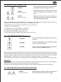
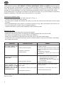
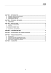
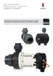
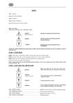
GB
CONTENTS
Ch.1- Features
Ch.5 - Starting the unit
Ch.2 - Limitations
Ch.6 - Maintenance and trouble shooting
Ch.3 - Installation
Ch.4 - Electrical connection
Warnings for the safety of individuals and things.
Please pay careful attention to the following signs and indications.
DANGER
Electric shock risk
Warns that the failure to follow directions may
cause electric shock.
DANGER
Warns that failure to follow directions could cause serious risk to persons or things.
WARNING
Warns that failure to follow directions could
damage the pump or installation.
WARNING: Before installing this pump read this manual carefully. Any damage caused by
failure to observe any directions in this manual will not be covered by warranty.
CH. 1 FEATURES
Electric pumps in the JET, NEWJET, JETINOX, GARDENJET, PURA and GARDY series are suitable for
pumping water for pressurising domestic installations, garden irrigation systems, fountains etc.
The electric pumps in this series are centrifugal and self-priming with a “venturi“ system inserted into
the body of the pump.
The electric pumps JET, NEWJET and JETINOX, are known as GARDENJET when they are equipped
with a power supply cord, switch and handle.
PURA DOM and GARDY are supplied with a power supply cord, switch and handle.
Upon request it is possible to obtain a suction kit for the pumps in this series. It consists of a 4 or 7 meter
pipe complete with a foot valve.
The parts that come into contact with the water are all suitable for use with water for cooking. Each
electropump is carefully tested and packed.
Please ensure that the electropump has not been damaged during transport; if this occurs please
phone the dealer, within 8 days from purchase date.
CH. 2 LIMITATIONS
WARNING
WARNING
Electropump cannot be used to move
inflammable or dangerous liquids.
Ensure electropump never runs dry.
5
GB
MAX. TEMPERATURE OF LIQUID..........................................
MAX. ROOM TEMPERATURE................................................
MAX.ON/OFF CYCLES/HOUR..............................................
MAXIMUM SUCTION HEIGHT................................................
MAXIMUM WORKING PRESSURE.........................................
MAXIMUM WORKING PRESSURE..........................................
MAXIMUM DIMENSION OF SOLID OBJECTS PUMPED............
50°C continuous operation
40°C
40 equally spaced
9 m including load losses
6 bar (excluding PURA and GARDY)
5 bar PURA and GARDY
3 mm
CH. 3 INSTALLATION (See Fig. 1)
DANGER
Risk of electric shock
When installing, please ensure
electropump is disconnected from
electrical supply.
WARNING
Protect the electropump and all pipes
from bad weather or freezing conditions.
If the electropump is to be installed a suction pipe 2 should be used with a diameter equal to that of the
suction duct for electropump 1. If the height HA is over 4 meters use a tube with a larger diameter.
The suction pipe must not have “goose-necks” or be inclined improperly in order to avoid the formation
of air pockets.
Make sure that the pipe is perfectly air tight.
At one end of the suction tube install a foot valve 3 with filter 4. The pipe should be submerged at least
50 cm. into the liquid to be pumped HI, in order to avoid the formation of whirlwinds.
To avoid load loss on delivery, a pipe with a diameter equal to or greater than the intake of electropump
5 should be used.
It is advisable to install a non-return valve 6 directly on the delivery pipe, this makes it possible to
eliminate any damage water hammers may cause to the electropump. After the non-return valve an
interception valve 7 should be installed. The pipes must be placed so that their weight does not interfere
with the electropump. The delivery and suctions pipes must travel the shortest distance with the
fewest possible number of bends.
If the installation is fixed then the electropump should be blocked on the support surface 11. In order to
reduce installation vibration the electropump should be connected with a length of flexible tubing and a
layer of rubber or other anti-vibration material should be inserted between the electropump and the
support surface.
If the electropump is moveable (equipped with a handle) it can be used in a pool only if there are no
people in it and if the installation is equipped with a shockproof switch.
Make sure that the motor is well ventilated.
WARNING !!!
The suction and delivery points for electric pumps in the PURA and GARDY series are made of plastic,
therefore particular care must be taken when mounting the pipes, avoiding the use of excessive force
when screwing fittings or other accessories and using Teflon tape to seal the connections.
The plastic coupling (pos. 40 fig.6) equipped with the pump should be used.
6
GB
CH. 4 ELECTRICAL CONNECTION
WARNING
Ensure tension and frequency of electropump
(read plate) and power supply are same.
Electric shock risk
Installer must make sure that electric current
network has ground wire conforming to current
laws.
DANGER
Electric shock risk
Make sure that electric current network is
provided with a high-sensitivity circuit breaker
DANGER
,=30 mA (DIN VDE 0100T739).
The single phase motors are protected from overloads by a thermal device installed in the winding. The
protection for the three phase motor must be installed by the user.
The following must be used as a conductor for the connection:
- outdoors → cable H07RN-F
- in inside areas → cable H05RN-F or H07RN-F
For connecting single phase motors see Fig. 2
For connecting three phase motors see Fig. 3
For connecting double voltage single phase motors see Fig. 4
CH. 5 STARTING THE UNIT (See Fig. 1)
WARNING
Use the electropump for the type of uses listed on
the plate.
WARNING
Do not let electropump run dry, the hydraulic parts
and seal could be damaged.
WARNING
Do not run the electropump with the interception
valve on delivery completely closed.
Before starting the electropump fill the suction pipe 2 and the electropump body 8 with water by using
the filling cap 9, making sure that there are no leaks, close the cap and start the electropump. Check that
it rotates clockwise when looking at the electropump from the side of the motor fan. On the three phase
electropumps it is possible to invert the rotation by changing the order of two phases.
If the electropump is not used for long periods of time repeat the filling operations before starting it up.
WARNING !!!
The electric pumps in this series can be started even without filling the suction pipe, by only filling the
pump body, in this case the pump will take a few minutes to prime.
The amount of time needed to prime will depend on the length and diameter of the suction pipe.
CH. 6 MAINTENANCE AND TROUBLE SHOOTING
DANGER
Electric shock risk
Before doing any operation, make sure machine is
disconnected from electric power supply.
7
GB
Under normal conditions JET, NEWJET, JETINOX, GARDENJET, PURA and GARDY electropumps do
not need any type of maintenance. In order to avoid possible failures, it is advisable to periodically
check the pressure supplied and current absorption. A decrease in pressure is a symptom of wear. An
increase in current absorption is a sign of abnormal mechanical friction in the pump and/or motor.
If the electropump is not going to be used for long periods of time (e.g. an entire season) it should be
emptied completely, rinsed with clean water and put in a dry place.
Cleaning the hydraulic parts:
- empty the pump body using the drain cap (pos. 10, fig. 1);
- unscrew the pump body fixing screws;
- by pushing with a plastic tool extract the venturi unit from the suction point and wash it with a spray
of water;
- when reassembling be very careful to correctly insert the O ring, that is mounted on the venturi unit,
into the suction point. If the O ring is damaged replace it.
Insertion the venturi unit into the pump body must be done by hand.
Replacing the seal:
- disassemble the pump body and unscrew the impeller;
- extract the seal using a pliers and pulling and rotating towards the end of the shaft;
- take off the seal holder flange (except PURA and GRADY);
- extract the counterface by pushing from the back side of the seal holder flange;
- to assemble, the counterface and seal must be inserted without using any tools and by lubricating
their seats with alcohol.
PROBLEM
POSSIBLE CAUSE
THE ELECTROPUMP DOES 1) No power.
NOT PUMP WATER THE
MOTOR DOES NOT RUN
2) Motor protection tripped.
3) Defective condenser.
4) Shaft blocked.
THE MOTOR RUNS BUT THE 1) It is taking on air.
ELECTROPUMP DOES NOT
PUMP LIQUID
2) Wrong rotation direction.
REMEDY
1) Check if there is power and if the plug is
plugged in properly.
2) Verify the cause and reset the switch. If the
thermal has tripped wait until the system has
cooled.
3) Replace the condenser.
4) Verify the cause and unblock the
electropump.
1) - Make sure that the joints are airtight.
- Check that the level of liquid has not
dropped below the foot valve.
- Check that the foot valve is airtight and
is not blocked.
2) Reset the rotation direction.
THE ELECTROPUMP STOPS
1) Power supply does not conform to 1) Check the voltage on the power supply
AFTER RUNNING FOR A
conductor cables.
SHORT PERIOD OF TIME data on plate.
BECAUSE ONE OF THE
THERMAL MOTOR PROTEC- 2) A solid object is blocking the impeller. 2) Dismantle the electropump and clean it.
TION DEVICES TRIPS
3) The liquid is too thick.
3) Change electropump type.
If the problem has not been eliminated after carrying out the above operations contact the closest
service centre.
8