1
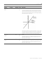
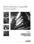
Motion Modules in
Logix5000 Control
Systems
Catalog Numbers 1756-HYD02,
1756-L60M03SE, 1756-M02AE,
1756-M02AS, 1756-M03SE,
1756-M08SE, 1756-M16SE,
1768-M04SE
User Manual
Important User Information
Solid state equipment has operational characteristics differing from those of
electromechanical equipment. Safety Guidelines for the Application,
Installation and Maintenance of Solid State Controls (publication SGI-1.1
available from your local Rockwell Automation sales office or online at
http://literature.rockwellautomation.com) describes some important
differences between solid state equipment and hard-wired electromechanical
devices. Because of this difference, and also because of the wide variety of
uses for solid state equipment, all persons responsible for applying this
equipment must satisfy themselves that each intended application of this
equipment is acceptable.
In no event will Rockwell Automation, Inc. be responsible or liable for
indirect or consequential damages resulting from the use or application of
this equipment.
The examples and diagrams in this manual are included solely for illustrative
purposes. Because of the many variables and requirements associated with
any particular installation, Rockwell Automation, Inc. cannot assume
responsibility or liability for actual use based on the examples and diagrams.
No patent liability is assumed by Rockwell Automation, Inc. with respect to
use of information, circuits, equipment, or software described in this manual.
Reproduction of the contents of this manual, in whole or in part, without
written permission of Rockwell Automation, Inc., is prohibited.
Throughout this manual, when necessary, we use notes to make you aware
of safety considerations.
WARNING
IMPORTANT
ATTENTION
Identifies information about practices or circumstances that can cause
an explosion in a hazardous environment, which may lead to personal
injury or death, property damage, or economic loss.
Identifies information that is critical for successful application and
understanding of the product.
Identifies information about practices or circumstances that can lead
to personal injury or death, property damage, or economic loss.
Attentions help you identify a hazard, avoid a hazard, and recognize
the consequence
SHOCK HAZARD
Labels may be on or inside the equipment, for example, a drive or
motor, to alert people that dangerous voltage may be present.
BURN HAZARD
Labels may be on or inside the equipment, for example, a drive or
motor, to alert people that surfaces may reach dangerous
temperatures.
Allen-Bradley, CompactLogix, ControlLogix, Logix5000, Logix, Rockwell Automation, TechConnect, PLC-5, SLC 500, Logix5550,
PowerFlex 700S, RSLogix 5000, DriveLogix, PowerFlex, and SoftLogix are trademarks of Rockwell Automation, Inc.
Trademarks not belonging to Rockwell Automation are property of their respective companies.
Summary of Changes
Introduction
This publication has new and updated information. To find new and
updated information, look for change bars, as shown next to this
paragraph.
Updated Information
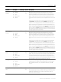
This document has these changes.
3
Change
See
Added Motion Analyzer and Project Sample information
Preface
Updated screen graphics to coincide with software release.
Chapters 1, 2, 4, 5 and Appendix C
Added MCT and MCTP Instruction information.
Chapter 2
Added new chapter about Kinematics.
Chapter 6
Added new introduction information to include articulated
independent and articulated dependent robotic arms.
Chapter 4
Added information about the Geometry Wizard and Offset Wizard
dialogs.
Chapter 4
Added information about the Offset, Geometry, Joint tabs that were
added to the Coordinate System Properties dialog.
Chapter 4
Moved the descriptions of Coordinate System attributes to an
appendix.
Appendix F
Added Transform Source Status and Transform Target information.
Appendix F
Added dialog information for tuning.
Appendix B
Added attribute information.
Appendix C
Added Transform Dimension information.
Chapter 4
Added Phase Loss information and updated dialog.
Appendix B
Created new heading and added Axis_Servo_Drive information.
Appendix B
Added information for maximum acceleration and deceleration jerk
Appendix B
Publication LOGIX-UM002B-EN-P - January 2007
Summary of Changes
4
Notes:
Publication LOGIX-UM002B-EN-P - January 2007
Table of Contents
Preface
Introduction . . . . . . . . . . . . . . . . . . .
Description of the Modules . . . . . . . .
Additional Resources. . . . . . . . . . . . .
Help for Selecting Drives and Motors.
Where to Find Sample Projects . . . . .
.
.
.
.
.
.
.
.
.
.
.
.
.
.
.
.
.
.
.
.
.
.
.
.
.
.
.
.
.
.
.
.
.
.
.
.
.
.
.
.
.
.
.
.
.
.
.
.
.
.
.
.
.
.
.
.
.
.
.
.
.
.
.
.
.
.
.
.
.
.
.
.
.
.
.
.
.
.
.
.
.
.
.
.
.
. 9
. 9
10
10
11
Introduction . . . . . . . . . . . . . . . . . . . .
Make the Controller the Master Clock .
Add the Motion Modules . . . . . . . . . . .
Add SERCOS interface Drives . . . . . . .
Set Up Each SERCOS Interface Module
Add the Motion Group . . . . . . . . . . . .
Add Your Axes . . . . . . . . . . . . . . . . . .
Set Up Each Axis. . . . . . . . . . . . . . . . .
Check the Wiring of Each Drive. . . . . .
Tune Each Axis. . . . . . . . . . . . . . . . . .
Get Axis Information . . . . . . . . . . . . . .
Program Motion Control . . . . . . . . . . .
What’s Next? . . . . . . . . . . . . . . . . . . . .
.
.
.
.
.
.
.
.
.
.
.
.
.
.
.
.
.
.
.
.
.
.
.
.
.
.
.
.
.
.
.
.
.
.
.
.
.
.
.
.
.
.
.
.
.
.
.
.
.
.
.
.
.
.
.
.
.
.
.
.
.
.
.
.
.
.
.
.
.
.
.
.
.
.
.
.
.
.
.
.
.
.
.
.
.
.
.
.
.
.
.
.
.
.
.
.
.
.
.
.
.
.
.
.
.
.
.
.
.
.
.
.
.
.
.
.
.
.
.
.
.
.
.
.
.
.
.
.
.
.
.
.
.
.
.
.
.
.
.
.
.
.
.
.
.
.
.
.
.
.
.
.
.
.
.
.
.
.
.
.
.
.
.
.
.
.
.
.
.
.
.
.
.
.
.
.
.
.
.
.
.
.
.
.
.
.
.
.
.
.
.
.
.
.
.
.
.
.
.
.
.
.
.
.
.
.
.
.
13
14
15
16
17
18
20
21
24
25
26
27
29
Introduction . . . . . . . . . . . . . . . . . . . . . . . . . . . . . . . . . . . .
Access Motion Direct Commands. . . . . . . . . . . . . . . . . . . . .
Choose a Command . . . . . . . . . . . . . . . . . . . . . . . . . . . . . .
Motion Direct Command Dialog . . . . . . . . . . . . . . . . . . . . .
Motion Direct Command Error Process. . . . . . . . . . . . . . . . .
What If the Software Goes Offline or the Controller Changes
Modes? . . . . . . . . . . . . . . . . . . . . . . . . . . . . . . . . . . . . . . . .
Can Two Workstations Give Motion Direct Commands? . . . .
31
32
34
37
39
Chapter 1
Start
Chapter 2
Test an Axis with Motion Direct
Commands
42
42
Chapter 3
Handle Faults
Introduction . . . . . . . . . . . . . . . . . . . . . . . . . . . . .
Choose If Motion Faults Shut Down the Controller .
Choose the Fault Actions for an Axis . . . . . . . . . . .
Set the Fault Action for an Axis . . . . . . . . . . . . . . .
.
.
.
.
.
.
.
.
.
.
.
.
.
.
.
.
.
.
.
.
.
.
.
.
.
.
.
.
43
44
45
46
Chapter 4
Create and Configure a Coordinate Introduction . . . . . . . . . . . . . . . . . . . . . . . . . . . . . . . . . . . . 47
Create a Coordinate System . . . . . . . . . . . . . . . . . . . . . . . . . 48
System
Entering Tag Information. . . . . . . . . . . . . . . . . . . . . . . . . . . 48
Editing Coordinate System Properties. . . . . . . . . . . . . . . . . . 52
5
Publication LOGIX-UM002B-EN-P - January 2007
Table of Contents
6
Chapter 5
Inhibit an Axis
Introduction . . . . . . . . . . . .
When to Inhibit an Axis . . .
Before You Begin . . . . . . . .
Example: Inhibit an Axis . . .
Example: Uninhibit an Axis .
.
.
.
.
.
.
.
.
.
.
.
.
.
.
.
.
.
.
.
.
.
.
.
.
.
.
.
.
.
.
.
.
.
.
.
.
.
.
.
.
.
.
.
.
.
.
.
.
.
.
.
.
.
.
.
.
.
.
.
.
.
.
.
.
.
.
.
.
.
.
.
.
.
.
.
.
.
.
.
.
.
.
.
.
.
.
.
.
.
.
.
.
.
.
.
.
.
.
.
.
.
.
.
.
.
.
.
.
.
.
.
.
.
.
.
.
.
.
.
.
71
71
72
75
76
Introduction . . . . . . . . . . . . . . . . . . . . . . . . . . . . . . . .
Overview of Kinematics Functionality in RSLogix 5000 .
Useful Terms . . . . . . . . . . . . . . . . . . . . . . . . . . . . . . .
Gather Information about Your Robot . . . . . . . . . . . . .
Summary of Kinematic Steps . . . . . . . . . . . . . . . . . . . .
Determine the Coordinate System Type . . . . . . . . . . . .
Configure an Articulated Independent Robot . . . . . . . .
Configure an Articulated Dependent Robot . . . . . . . . .
Configure a Cartesian Gantry Robot . . . . . . . . . . . . . . .
Configure a Cartesian H-bot . . . . . . . . . . . . . . . . . . . .
Configure a SCARA . . . . . . . . . . . . . . . . . . . . . . . . . . .
Arm Solutions . . . . . . . . . . . . . . . . . . . . . . . . . . . . . . .
Left-Arm and Right-Arm Solutions for Two-Axes Robots
Solution Mirroring for Three-Dimensional Robots . . . . .
Activating Kinematics . . . . . . . . . . . . . . . . . . . . . . . . .
Change the Robot Arm Solution. . . . . . . . . . . . . . . . . .
Plan for Singularity . . . . . . . . . . . . . . . . . . . . . . . . . . .
Encounter a No-solution Position. . . . . . . . . . . . . . . . .
Error Conditions . . . . . . . . . . . . . . . . . . . . . . . . . . . . .
.
.
.
.
.
.
.
.
.
.
.
.
.
.
.
.
.
.
.
.
.
.
.
.
.
.
.
.
.
.
.
.
.
.
.
.
.
.
.
.
.
.
.
.
.
.
.
.
.
.
.
.
.
.
.
.
.
.
.
.
.
.
.
.
.
77
77
79
79
80
82
84
94
102
103
106
110
110
110
111
112
112
113
113
.
.
.
.
.
.
.
.
.
.
.
.
.
.
.
115
115
117
120
123
Introduction . . . . . . . . . . . . . . . . . . . . . . . . . . . . . . . . .
Why does my axis accelerate when I stop it? . . . . . . . . .
Why does my axis overshoot its target speed? . . . . . . . .
Why is there a delay when I stop and then restart a jog?.
Why does my axis reverse dir. when I stop and start it? .
.
.
.
.
.
.
.
.
.
.
125
125
127
130
132
Chapter 6
Kinematics in RSLogix 5000
Software
Chapter 7
Interpret Module Lights (LEDs)
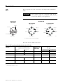
Introduction . . . . . . . . . .
1756-M02AE Module . . . .
1756-M02AS Module . . . .
1756-HYD02 Module. . . .
SERCOS interface Module
.
.
.
.
.
.
.
.
.
.
.
.
.
.
.
.
.
.
.
.
.
.
.
.
.
.
.
.
.
.
.
.
.
.
.
.
.
.
.
.
.
.
.
.
.
.
.
.
.
.
.
.
.
.
.
.
.
.
.
.
.
.
.
.
.
.
.
.
.
.
.
.
.
.
.
.
.
.
.
.
.
.
.
.
.
.
.
.
.
.
.
.
.
.
.
.
.
.
.
.
.
.
.
.
.
.
.
.
.
.
Chapter 8
Troubleshoot Axis Motion
Publication LOGIX-UM002B-EN-P - January 2007
Table of Contents
7
Chapter 9
Configure Homing
Introduction . . . . . . . . . . . . . . . . . . . . . . . . . . . . . . . . . . . 135
Guidelines for Homing . . . . . . . . . . . . . . . . . . . . . . . . . . . 135
Examples . . . . . . . . . . . . . . . . . . . . . . . . . . . . . . . . . . . . . 136
Appendix A
Wiring Diagrams
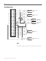
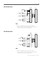
Introduction . . . . . . . . . . . . . . . . . . . . . .
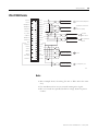
1756-M02AE Module . . . . . . . . . . . . . . . .
Ultra 100 Series Drive . . . . . . . . . . . . . . .
Ultra 200 Series Drive . . . . . . . . . . . . . . .
Ultra3000 Drive. . . . . . . . . . . . . . . . . . . .
1394 Servo Drive (in Torque Mode only) .
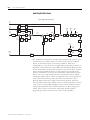
1756-M02AS Module . . . . . . . . . . . . . . . .
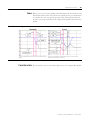
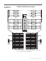
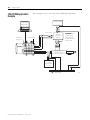
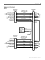
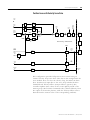
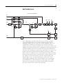
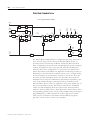
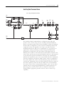
1756-HYD02 Application Example . . . . . .
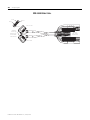
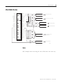
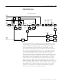
1756-HYD02 Module . . . . . . . . . . . . . . . .
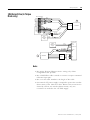
LDTs . . . . . . . . . . . . . . . . . . . . . . . . . . .
Temposonic GH Feedback Device . . . . . .
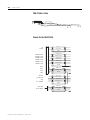
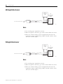
24V Registration Sensor . . . . . . . . . . . . . .
5V Registration Sensor. . . . . . . . . . . . . . .
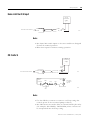
Home Limit Switch Input. . . . . . . . . . . . .
OK Contacts . . . . . . . . . . . . . . . . . . . . . .
.
.
.
.
.
.
.
.
.
.
.
.
.
.
.
.
.
.
.
.
.
.
.
.
.
.
.
.
.
.
.
.
.
.
.
.
.
.
.
.
.
.
.
.
.
.
.
.
.
.
.
.
.
.
.
.
.
.
.
.
.
.
.
.
.
.
.
.
.
.
.
.
.
.
.
.
.
.
.
.
.
.
.
.
.
.
.
.
.
.
.
.
.
.
.
.
.
.
.
.
.
.
.
.
.
.
.
.
.
.
.
.
.
.
.
.
.
.
.
.
.
.
.
.
.
.
.
.
.
.
.
.
.
.
.
.
.
.
.
.
.
.
.
.
.
.
.
.
.
.
.
.
.
.
.
.
.
.
.
.
.
.
.
.
.
.
.
.
.
.
.
.
.
.
.
.
.
.
.
.
.
.
.
.
.
.
.
.
.
.
.
.
.
.
.
141
142
143
143
145
147
149
150
151
152
153
154
154
155
155
Introduction . . . . . . . . . . . . . . . . . . . . . . . . . . . . . . .
General Tab – AXIS_SERVO . . . . . . . . . . . . . . . . . . .
General Tab - AXIS_SERVO_DRIVE . . . . . . . . . . . . . .
General Tab - AXIS_VIRTUAL . . . . . . . . . . . . . . . . . .
General Tab – AXIS_GENERIC. . . . . . . . . . . . . . . . . .
Motion Planner Tab. . . . . . . . . . . . . . . . . . . . . . . . . .
Units Tab . . . . . . . . . . . . . . . . . . . . . . . . . . . . . . . . .
Servo Tab - AXIS_SERVO . . . . . . . . . . . . . . . . . . . . .
Feedback Tab – (AXIS_SERVO) . . . . . . . . . . . . . . . . .
Drive/Motor Tab - (AXIS_SERVO_DRIVE) . . . . . . . . .
Motor Feedback Tab - AXIS_SERVO_DRIVE . . . . . . . .
Aux Feedback Tab - AXIS_SERVO_DRIVE . . . . . . . . .
Conversion Tab. . . . . . . . . . . . . . . . . . . . . . . . . . . . .
Homing Tab - AXIS_SERVO. . . . . . . . . . . . . . . . . . . .
Homing Tab - AXIS_SERVO_DRIVE . . . . . . . . . . . . . .
Homing Tab - AXIS_VIRTUAL . . . . . . . . . . . . . . . . . .
Hookup Tab - AXIS_SERVO . . . . . . . . . . . . . . . . . . .
Hookup Tab Overview - AXIS_SERVO_DRIVE . . . . . .
Tune Tab - AXIS_SERVO, AXIS_SERVO_DRIVE . . . . .
Dynamics Tab - AXIS_SERVO, AXIS_SERVO _DRIVE,
AXIS_VIRTUAL . . . . . . . . . . . . . . . . . . . . . . . . . . . . .
Gains Tab - AXIS_SERVO . . . . . . . . . . . . . . . . . . . . .
.
.
.
.
.
.
.
.
.
.
.
.
.
.
.
.
.
.
.
.
.
.
.
.
.
.
.
.
.
.
.
.
.
.
.
.
.
.
.
.
.
.
.
.
.
.
.
.
.
.
.
.
.
.
.
.
.
.
.
.
.
.
.
.
.
.
.
.
.
.
.
.
.
.
.
.
157
157
158
162
163
164
167
168
170
175
182
183
185
186
191
195
196
198
200
Appendix B
Axis Properties
. . . . 203
. . . . 208
Publication LOGIX-UM002B-EN-P - January 2007
Table of Contents
8
Gains Tab - AXIS_SERVO_DRIVE. . . . . . . . . .
Output Tab - AXIS_SERVO . . . . . . . . . . . . . .
Output Tab Overview - AXIS_SERVO_DRIVE .
Limits Tab - AXIS_SERVO . . . . . . . . . . . . . . .
Limits Tab - AXIS_SERVO_DRIVE . . . . . . . . .
Offset Tab - AXIS_SERVO . . . . . . . . . . . . . . .
Offset Tab - AXIS_SERVO_DRIVE . . . . . . . . .
Fault Actions Tab - AXIS_SERVO . . . . . . . . . .
Fault Actions Tab - AXIS_SERVO_DRIVE . . . .
Tag Tab . . . . . . . . . . . . . . . . . . . . . . . . . . . .
.
.
.
.
.
.
.
.
.
.
.
.
.
.
.
.
.
.
.
.
.
.
.
.
.
.
.
.
.
.
.
.
.
.
.
.
.
.
.
.
.
.
.
.
.
.
.
.
.
.
.
.
.
.
.
.
.
.
.
.
.
.
.
.
.
.
.
.
.
.
.
.
.
.
.
.
.
.
.
.
.
.
.
.
.
.
.
.
.
.
.
.
.
.
.
.
.
.
.
.
213
220
224
228
232
238
241
245
248
253
Appendix C
Axis Attributes
Introduction . . . . . . . . . . . . . . . . . . . . . . . . . . . . . . . . . . . 257
How to Access Attributes. . . . . . . . . . . . . . . . . . . . . . . . . . 257
Axis Attributes . . . . . . . . . . . . . . . . . . . . . . . . . . . . . . . . . 258
Appendix D
Servo Loop Block Diagrams
Introduction . . . . . . . . . .
Interpreting the Diagrams
AXIS_SERVO. . . . . . . . . .
AXIS_SERVO_DRIVE . . . .
.
.
.
.
.
.
.
.
.
.
.
.
.
.
.
.
.
.
.
.
.
.
.
.
.
.
.
.
.
.
.
.
.
.
.
.
.
.
.
.
.
.
.
.
.
.
.
.
.
.
.
.
.
.
.
.
.
.
.
.
.
.
.
.
.
.
.
.
.
.
.
.
.
.
.
.
.
.
.
.
.
.
.
.
.
.
.
.
.
.
.
.
.
.
.
.
.
.
.
.
367
367
368
370
.
.
.
.
.
.
.
.
.
.
.
.
.
.
.
.
.
.
.
.
.
.
.
.
.
.
.
.
.
.
.
.
.
.
.
.
.
.
.
.
.
.
.
.
.
.
.
.
.
.
.
.
.
.
.
.
.
.
.
.
.
.
.
.
.
.
.
.
.
.
.
.
.
.
.
.
.
.
.
.
.
.
.
.
.
.
.
.
.
.
.
.
.
.
.
.
.
.
.
.
.
.
.
.
.
.
.
.
.
.
.
.
.
.
.
.
.
.
.
.
.
.
.
.
.
.
.
.
.
.
.
.
.
.
.
.
.
.
.
.
.
.
.
.
.
.
.
.
.
.
379
379
382
384
387
391
Appendix E
Axis Data Types
Introduction . . . . . . .
AXIS_CONSUMED. . .
AXIS_GENERIC . . . . .
AXIS_SERVO. . . . . . .
AXIS_SERVO_DRIVE .
AXIS_VIRTUAL . . . . .
.
.
.
.
.
.
.
.
.
.
.
.
.
.
.
.
.
.
Appendix F
Coordinate System Attributes
Publication LOGIX-UM002B-EN-P - January 2007
How to Access Attributes. . . . . . . . . . . . . . . . . . . . . . . . . . 393
Coordinate System Attributes . . . . . . . . . . . . . . . . . . . . . . . 393
Preface
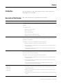
Introduction
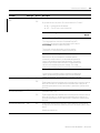
Use this manual to setup and program motion control using these
Logix5000 motion modules.
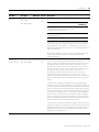
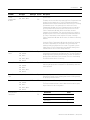
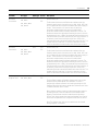
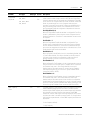
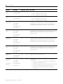
Description of the Modules
This table describes the Logix5000 motion modules.
Motion Module
Description
1756-M02AE
The 1756-M02AE is a two-axis servo module for drives/actuators that need a ±10V velocity
or torque reference. Use the 1756-M02AE when your equipment has quadrature encoder
feedback.
The module also has:
• Home limit switch inputs
• Drive fault inputs
• Drive enable outputs
• 5V or 24V position registration inputs
• 250 μs position and velocity loop updates
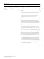
1756-HYD02
The 1756-HYD02 is a two-axis servo module for hydraulic actuators that need a ±10V
velocity reference. Use the 1756-HYD02 when your equipment has magnostrictive linear
transducer (LDT) feedback.
The module is similar to the 1756-M02AE with these exceptions:
• Feed Forward adjust in addition to single-step Auto Tune.
• Gain ratio between extend direction and retract direction to accommodate hydraulic
cylinder dynamics.
• Intelligent transducer noise detection filtering in hardware and firmware replaces
programmable IIR filtering.
1756-M02AS
The 1756-M02AS is a two-axis servo module for drives/actuators that need a ±10 volt
velocity or torque reference input. Use the 1756-M02AS when your equipment has Serial
Synchronous Input (SSI) position feedback.
The module is similar to the 1756-M02AE with these exceptions:
• Gain ratio between extend direction and retract direction to accommodate hydraulic
cylinder dynamics.
• Intelligent transducer noise detection filtering in hardware and firmware replaces
programmable IIR filtering.
• SSI interface consisting of Differential Clock output and Data return signals
replaces the differential encoder interface.
1756-M03SE
1756-M08SE
1756-M16SE
1768-M04SE
Use a SERCOS interface module to connect the controller to SERCOS interface drives.
• The SERCOS interface lets you control digital drives using high-speed, real time,
serial communication.
• SERCOS is the IEC 61491 SErial Real-time COmmunication System protocol over a
fiber optic network.
• The module uses a fiber optic network for all the wiring between the drives and the
module.
9
Publication LOGIX-UM002B-EN-P - January 2007
Preface
10
Additional Resources
Help for Selecting Drives
and Motors
Publication LOGIX-UM002B-EN-P - January 2007
See these manuals for more information about using motion modules
in a Logix5000 control system.
Publication
Publication Number
Logix5000 Controllers Quick Start
1756-QS001
Logix5000 Controllers Common Procedures
1756-PM001
Logix5000 Controller Motion Instructions Reference Manual
1756-RM007
Logix5000 Controllers General Instructions Reference Manual
1756-RM003
Logix5000 Controllers Process and Drives Instructions
Reference Manual
1756-RM006
PhaseManager User Manual
LOGIX-UM001
ControlLogix Controller User Manual
1756-UM001
CompactLogix Controllers User Manual
1768-UM001
Analog Encoder (AE) Servo Module Installation Instructions
1756-IN047
ControlLogix SERCOS interface Module Installation
Instructions
1756-IN572
CompactLogix SERCOS interface Module Installation
Instructions
1768-IN005
1394 SERCOS Interface Multi Axis Motion Control System
Installation Manual
1394-IN002
1394 SERCOS Integration Manual
1394-IN024
Ultra3000 Digital Servo Drives Installation Manual
2098-IN003
Ultra3000 Digital Servo Drives Integration Manual
2098-IN005
Kinetix 6000 Installation Manual
2094-IN001
Kinetix 6000 Integration Manual
2094-IN002
8720MC High Performance Drive Installation Manual
8720MC-IN001
8720MC High Performance Drive Integration Manual
8720MC-IN002
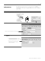
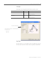
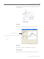
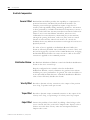
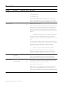
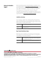
The Motion Analyzer utility helps you select the appropriate Rockwell
drives and motors based upon your load characteristics and typical
motion application cycles. The Motion Analyzer guides you through
wizard-like screens to collect information specific to your application.
After you enter the information (such as load inertia, gear box ratio,
feedback device and brake requirements all available through the
robot manufacturer) the Motion Analyzer generates an easy-to-read list
of recommended motors, drives and other support equipment to
interface with the type of robot you are using.
Preface
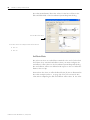
Where to Find Sample
Projects
11
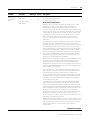
Sample projects from Rockwell Automation as well as other vendors
are available from the RSLogix 5000 software Help system menu.
Publication LOGIX-UM002B-EN-P - January 2007
Preface
12
Publication LOGIX-UM002B-EN-P - January 2007
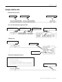
Chapter
1
Start
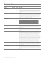
Introduction
Use this chapter for step-by-step procedures on how to set up motion
control.
IMPORTANT
If you aren’t using SERCOS interface drives and modules, skip
tasks 3 and 4.
Topic
13
See page
1. Make the Controller the Master Clock
14
2. Add the Motion Modules
15
3. Add SERCOS interface Drives
16
4. Set Up Each SERCOS Interface Module
17
5. Add the Motion Group
18
6. Add Your Axes
20
7. Set Up Each Axis
21
8. Check the Wiring of Each Drive
24
9. Tune Each Axis
25
10. Get Axis Information
26
11. Program Motion Control
27
12. What’s Next?
29
Publication LOGIX-UM002B-EN-P - January 2007
14
Start
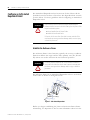
Make the Controller the
Master Clock
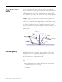
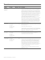
You must make one module in the chassis the master clock for motion
control. This module is called the coordinated system time (CST)
master. The motion modules set their clocks to the CST master.
In most cases, make the controller the CST master.
1.
2.
3.
4.
If you have more than one controller in the chassis
If you have more than one controller in the chassis, choose one of the
controllers to be the CST master. You can’t have more than one CST
master for the chassis.
Publication LOGIX-UM002B-EN-P - January 2007
Start
15
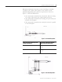
Add the Motion Modules
IMPORTANT
1.
CompactLogix controller
For your motion modules, use the firmware revision that goes with the
firmware revision of your controller. See the release notes for your
controller’s firmware.
ControlLogix controller
2.
3.
4.
5.
6.
7.
8.
Publication LOGIX-UM002B-EN-P - January 2007
16
Start
Add SERCOS interface
Drives
1.
Add SERCOS interface drives to the I/O configuration of the controller.
This lets you use RSLogix 5000 software to set up the drives.
CompactLogix controller
2.
3.
4.
5.
6. Node number of the drive on the SERCOS ring
7.
8.
Publication LOGIX-UM002B-EN-P - January 2007
ControlLogix controller
Start
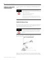
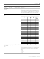
Set Up Each SERCOS
Interface Module
1.
17
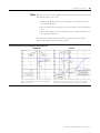
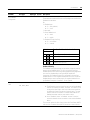
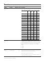
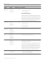
Set the data rate and cycle time for each SERCOS interface module in
your project.
CompactLogix controller
ControlLogix controller
2.
3.
4.
5.
Baud Rate of Drives
Number of Drives on the Ring
Type of Drives
Cycle Time
4 Mb
1 or 2
Kinetix 6000
0.5 ms
NOT Kinetix 6000
1 ms
8 Mb
3 or 4
1 ms
5…8
2 ms
9…16
Can’t do.
1…4
Kinetix 6000
0.5 ms
NOT Kinetix 6000
1 ms
5…8
1 ms
9…16
2 ms
Publication LOGIX-UM002B-EN-P - January 2007
18
Start
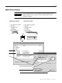
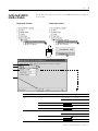
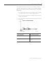
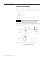
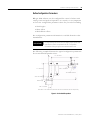
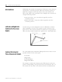
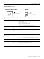
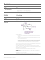
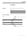
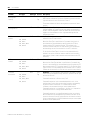
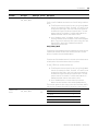
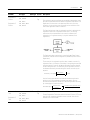
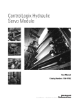
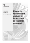
Add the Motion Group
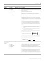
Add a motion group to set up the motion planner.
Motion Planner
Part of the controller that takes care of position and velocity information for your axes
Coarse Update Period
How often the motion planner runs. When the motion planner runs, it interrupts all other
tasks regardless of their priority.
Motion Planner
Scans of Your Code,
System Overhead, And
So On.
0 ms
10 ms
20 ms
30 ms
40 ms
In this example, the coarse update period = 10 ms. Every 10 ms the controller stops scanning your code
and whatever else it is doing and runs the motion planner.
IMPORTANT
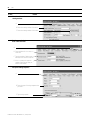
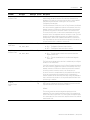
Action
1. Choose your coarse update
period.
Add only one motion group for the project. RSLogix 5000 software
doesn’t let you add more than one motion group.
Details
The coarse update period is a trade-off between updating positions of your axes and
scanning your code. Use these guidelines as a rough starting point.
A. How many axes do you have?
• Less than 11 axes — Set the coarse update period to 10 ms.
• 11 axes or more — Set the coarse update period to 1 ms per axis.
B. Leave at least half the controller’s time for the scan of all your code.
C. If you have SERCOS interface motion modules, set the coarse update period to a
multiple of the cycle time of the motion module.
Example: if the cycle time is 2 ms, set the coarse update period to 8 ms, 10 ms,
12 ms, and so on.
D. If you have analog motion modules, set the coarse update period to:
1. At least 3 times the servo update period of the motion module
2. A multiple of the servo update period of the motion module
Publication LOGIX-UM002B-EN-P - January 2007
Start
Action
19
Details
2. Add the motion group.
A.
B.
C.
D.
3. Set the coarse update period.
A.
B.
C.
Publication LOGIX-UM002B-EN-P - January 2007
20
Start
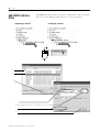
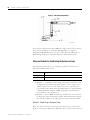
Add Your Axes
Action
Add an axis for each of your drives.
Details
1. Decide which data type to use.
If you use this motion module for the axis
Then use this data type
1756-M03SE
1756-M08SE
1756-M16SE
1756-L60M03SE
1768-M04SE
AXIS_SERVO_DRIVE
1756-M02AE
1756-HYD02
1756-M02AS
AXIS_SERVO
No hardware
AXIS_VIRTUAL
2. Add an axis.
Analog
SERCOS interface
A.
No Hardware
B.
C.
D.
Publication LOGIX-UM002B-EN-P - January 2007
Start
Set Up Each Axis
Action
21
The following steps show how to set up the axis of a SERCOS
interface drive. The steps are slightly different if you have a different
type of drive.
Details
1. Open the properties for the axis.
2. Select the drive for the axis.
Select the name that you gave to the drive for this
axis.
3. Set the units that you want to
program in.
A.
B. Type the units that you want to use for
programming, such as revs, degrees,
inches, or millimeters.
Publication LOGIX-UM002B-EN-P - January 2007
22
Start
Action
Details
4. Select the drive and motor
catalog numbers.
A.
B. Select the catalog number of the drive.
C. Select the catalog number of the motor.
5. Set the conversion between
drive counts and units.
A.
B. Select whether this is a rotary or
linear axis.
C. Type the number of drive counts
that equal one unit from Step 3B.
D. If this is a rotary axis, type the
number of drive counts that you
want to unwind after.
6. Set up the homing sequence.
A.
B. Select the type of homing sequence that
you want.
C. Type homing speeds.
Publication LOGIX-UM002B-EN-P - January 2007
Start
Action
23
Details
7. Apply your changes.
A.
B.
Publication LOGIX-UM002B-EN-P - January 2007
24
Start
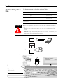
Check the Wiring of Each
Drive
ATTENTION
!
Use the hookup tests to check the wiring of a drive.
This Test
Does This
Notes
Test marker
Checks that the drive gets the marker
pulse.
You must manually move the
axis for this test.
Test feedback
Checks the polarity of the feedback.
You must manually move the
axis for this test.
Test command
and feedback
Checks the polarity of the drive.
These tests make the axis move even with the controller in remote
program mode.
• Before you do the tests, make sure no one is in the way of the
axis.
• Do not change the polarity after you do the tests. Otherwise you
may cause an axis-runaway condition.
1.
controller
download
2.
3.
4.
5.
6. Type how far you want the axis to move
during the tests.
7.
8.
9.
Publication LOGIX-UM002B-EN-P - January 2007
RUN REM PROG
drive
Start
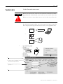
Tune Each Axis
25
Use the Tune tab to tune an axis.
ATTENTION
!
When you tune an axis, it moves even with the controller in remote
program mode. In that mode, your code is not in control of the axis.
Before you tune an axis, make sure no one is in the way of the axis.
The default tuning procedure tunes the proportional gains. Typically,
tune the proportional gains first and see how your equipment runs.
1.
controller
download
2.
3.
RUN REM PROG
drive
4.
5.
6. Type the limit of movement for the axis
during the tuning procedure.
7. Type the maximum speed for your
equipment.
8.
Publication LOGIX-UM002B-EN-P - January 2007
26
Start
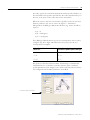
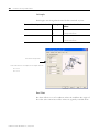
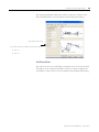
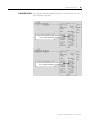
Get Axis Information
You can get information about an axis in several ways.
Use the Axis Properties window to configure the axis.
Use the Quick View pane to see the state
and faults of an axis.
Use a Get System Value (GSV) instruction or Set System Value (SSV)
instruction to read or change the configuration at run-time.
Use the tag of the axis for status and faults.
Publication LOGIX-UM002B-EN-P - January 2007
Start
Program Motion Control
See:
• Logix5000 Controllers Common
•
•
Procedures Manual, 1756-PM001
Logix5000 Controllers Motion
Instructions Reference Manual,
1756-RM007
Logix5000 Controllers General
Instructions Reference Manual,
1756-RM003
27
The controller gives you a set of motion control instructions for your
axes.
• Uses these instructions just like the rest of the Logix5000
instructions. You can program motion control in these
programming languages:
– ladder diagram (LD)
– structured text (ST)
– sequential function chart (SFC)
• Each motion instruction works on one or more axes.
• Each motion instruction needs a motion control tag. The tag
uses a MOTION_INSTRUCTION data type. The tag stores the
status information of the instruction.
Motion control tag
ATTENTION
!
Use the tag for the motion control operand of motion instruction
only once. Unintended operation of the control variables may
happen if you re-use of the same motion control tag in other
instructions.
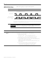
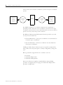
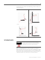
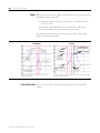
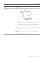
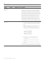
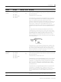
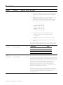
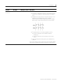
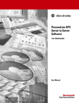
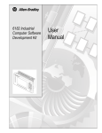
Example
Here’s an example of a simple ladder diagram that homes, jogs, and
moves an axis.
If Initialize_Pushbutton = on and the axis = off (My_Axis_X.ServoActionStatus = off) then
The MSO instruction turns on the axis.
If Home_Pushbutton = on and the axis hasn’t been homed (My_Axis_X.AxisHomedStatus = off) then
The MAH instruction homes the axis.
Publication LOGIX-UM002B-EN-P - January 2007
28
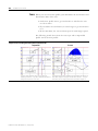
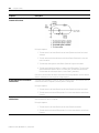
Start
If Jog_Pushbutton = on and the axis = on (My_Axis_X.ServoActionStatus = on) then
The MAJ instruction jogs the axis forward at 8 units/s.
If Jog_Pushbutton = off then
The MAS instruction stops the axis at 100 units/s2
Make sure that Change Decel is Yes. Otherwise, the axis decelerates at its maximum speed.
If Move_Command = on and the axis = on (My_Axis_X.ServoActionStatus = on) then
The MAM instruction moves the axis. The axis moves to the position of 10 units at 1 unit/s.
Publication LOGIX-UM002B-EN-P - January 2007
Start
What’s Next?
29
Use these chapters to continue programming your motion control
system.
•
•
•
•
•
Test an Axis with Motion Direct Commands
Configure Homing
Handle Faults
Create and Configure a Coordinate System
Inhibit an Axis
Publication LOGIX-UM002B-EN-P - January 2007
30
Start
Notes:
Publication LOGIX-UM002B-EN-P - January 2007
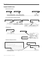
Chapter
2
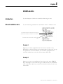
Test an Axis with Motion Direct Commands
Introduction
The Motion Direct Commands feature lets you issue motion
commands while you are online without having to write or execute an
application program. Motion Direct Commands are particularly useful
when you are commissioning or debugging a motion application.
During commissioning, you can configure an axis and monitor the
behavior using Trends in the Controller Organizer. Use of Motion
Direct Commands can “fine-tune” the system with or without load to
optimize its performance. When in the testing and or debugging cycle,
you can issue Motion Direct Commands to establish or reestablish
conditions such as Home. Often during initial development or
enhancement to mature applications you need to test the system in
small manageable areas. These tasks include:
• Home to establish initial conditions
• Incrementally Move to a physical position
• Monitor system dynamics under specific conditions
31
Publication LOGIX-UM002B-EN-P - January 2007
32
Test an Axis with Motion Direct Commands
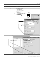
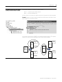
Access Motion Direct
Commands
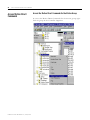
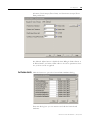
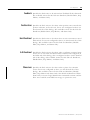
Access the Motion Direct Commands for the Motion Group
To access the Motion Direct Commands for the motion group, rightclick the group in the Controller Organizer.
Publication LOGIX-UM002B-EN-P - January 2007
Test an Axis with Motion Direct Commands
33
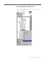
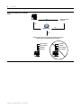
Access the Motion Direct Commands for an Axis
To access the Motion Direct Commands for an axis, right-click the axis
in the Controller Organizer.
Publication LOGIX-UM002B-EN-P - January 2007
34
Test an Axis with Motion Direct Commands
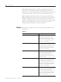
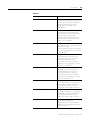
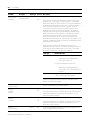
Choose a Command
Use this table to choose an instruction and see if it is available as a
Motion Direct Command.
If you want to
And
Use this instruction
Motion direct
Command
Change the state of an axis
Enable the servo drive and activate the axis servo
loop.
MSO
Yes
Disable the servo drive and deactivate the axis servo
loop.
MSF
Force an axis into the shutdown state and block any
instructions that initiate axis motion.
MASD
Transition an axis to the ready state. If all of the axes
of a servo module are removed from the shutdown
state as a result of this instruction, the OK relay
contacts for the module close.
MASR
Enable the servo drive and set the servo output
voltage of an axis.
MDO
Disable the servo drive and set the servo output
voltage to the output offset voltage.
MDF
Clear all motion faults for an axis.
MAFR
Motion Servo On
Yes
Motion Servo Off
Yes
Motion Axis Shutdown
Yes
Motion Axis Shutdown Reset
Yes
Motion Direct Drive On
Yes
Motion Direct Drive Off
Yes
Motion Axis Fault Reset
Control axis position
Stop any motion process on an axis.
MAS
Yes
Motion Axis Stop
Home an axis.
MAH
Yes
Motion Axis Home
Jog an axis.
MAJ
Yes
Motion Axis Jog
Move an axis to a specific position.
MAM
Yes
Motion Axis Move
Start electronic gearing between 2 axes
MAG
Yes
Motion Axis Gear
Change the speed, acceleration, or deceleration of a
move or a jog that is in progress.
MCD
Change the command or actual position of an axis.
MRP
Yes
Motion Change Dynamics
Yes
Motion Redefine Position
Calculate a Cam Profile based on an array of cam
points.
MCCP
Start electronic camming between 2 axes.
MAPC
No
Motion Calculate Cam Profile
No
Motion Axis Position Cam
Start electronic camming as a function of time.
MATC
No
Motion Axis Time Cam
Calculate the slave value, slope, and derivative of
the slope for a cam profile and master value.
Publication LOGIX-UM002B-EN-P - January 2007
MCSV
Motion Calculate Slave Values
No
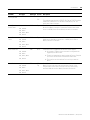
Test an Axis with Motion Direct Commands
35
If you want to
And
Use this instruction
Motion direct
Command
Initiate action on all axes
Stop motion of all axes.
MGS
Yes
Motion Group Stop
Force all axes into the shutdown state.
MGSD
Yes
Motion Group Shutdown
Transition all axes to the ready state.
MGSR
Yes
Motion Group Shutdown Reset
Latch the current command and actual position of all
axes.
Arm and disarm special event
Arm the watch-position event checking for an axis.
checking functions such as
registration and watch position
Disarm the watch-position event checking for an
axis.
Arm the servo-module registration-event checking
for an axis.
MGSP
Yes
Motion Group Strobe Position
MAW
Yes
Motion Arm Watch Position
MDW
Yes
Motion Disarm Watch Position
MAR
Yes
Motion Arm Registration
Disarm the servo-module registration-event checking MDR
Motion Disarm Registration
for an axis.
Yes
Arm an output cam for an axis and output.
No
MAOC
Motion Arm Output Cam
Disarm one or all output cams connected to an axis.
MDOC
No
Motion Disarm Output Cam
Tune an axis and run diagnostic Use the results of an MAAT instruction to calculate
tests for your control system.
and update the servo gains and dynamic limits of an
These tests include:
axis.
MAAT
• Motor/encoder hookup
test
Run a tuning motion profile for an axis
• Encoder hookup test
Use the results of an MRHD instruction to set
encoder and servo polarities.
MAHD
Run one of the diagnostic tests on an axis.
MRHD
• Marker test
No
Motion Apply Axis Tuning
MRAT
No
Motion Run Axis Tuning
No
Motion Apply Hookup Diagnostic
No
Motion Run Hookup Diagnostic
Publication LOGIX-UM002B-EN-P - January 2007
36
Test an Axis with Motion Direct Commands
If you want to
And
Use this instruction
Motion direct
Command
Control multi-axis coordinated
motion
Start a linear coordinated move for the axes of
coordinate system.
MCLM
No
Start a circular move for the for the axes of
coordinate system.
MCCM
Change in path dynamics for the active motion on a
coordinate system.
MCCD
Stop the axes of a coordinate system.
MCS
Motion Coordinated Linear Move
No
Motion Coordinated Circular
Move
No
Motion Coordinated Change
Dynamics
No
Motion Coordinated Stop
Shutdown the axes of a coordinate system.
MCSD
No
Motion Coordinated Shutdown
Transition the axes of a coordinate system to the
ready state and clear the axis faults.
MCSR
Start a transform that links two coordinate systems
together.
MCT()
Motion Coordinated
Transform
No
Calculate the position of one coordinate system with
respect to another coordinate system.
MCTP()
Motion Calculate Transform
Position
No
()
Publication LOGIX-UM002B-EN-P - January 2007
No
Motion Coordinated Shutdown
Reset
You can use this instruction only with 1756-L6x controllers.
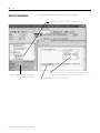
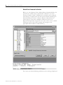
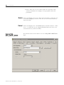
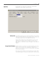
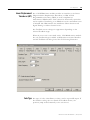
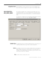
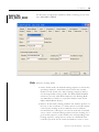
Test an Axis with Motion Direct Commands
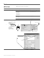
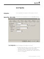
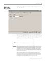
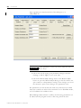
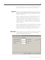
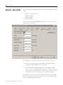
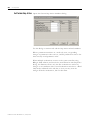
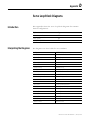
Motion Direct Command
Dialog
37
You must be online to execute a Motion Direct Command. The online
dialog has the Motion Group Shutdown and Execute buttons active. If
you click either of these, action is taken immediately.
Instance Designation
Active Command
Axis or Group Designation
Command
Tree
Operands
Status Text
Display Area
Action Buttons
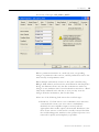
When the Motion Direct Command dialog is opened, focus is given to
the Command Tree. In the Command list, you can either type the
mnemonic and the list advances to the closest match or you can scroll
down the list to select a command. Click the desired command and its
dialog displays.
At the top of the dialog, in the title bar, there is a number at the end of
the axis or group that the command is being applied upon. This is the
Instance reference number. This number increases by one every time
a command is accessed for that axis or group. The number is cleared
when you execute RSLogix software.
Located at the bottom of the dialog are the following buttons: Motion
Group Shutdown, Execute, Close, and Help.
Publication LOGIX-UM002B-EN-P - January 2007
38
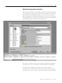
Test an Axis with Motion Direct Commands
Motion Group Shutdown Button
The Motion Group Shutdown button is located to the left of the screen
to avoid accidental invoking of this command when you really want
to execute the command accessed from the Command tree. Clicking
on this button causes the Motion Group Shutdown instruction to
execute. If you click on the Motion Group Shutdown button and it is
successfully executed, a Result message is displayed in the results
window below the dialog. Since the use of this button is an abrupt
means of stopping motion, an additional message is displayed in the
error text field. The message "MOTION GROUP SHUTDOWN
executed!" is displayed with the intention of giving greater awareness
of the execution of this command. If the command fails then an error
is indicated as per normal operation. (See Error Conditions later in this
chapter.)
There is space above the Motion Group Shutdown button and below
the line where status text is displayed when a command is executed.
Execute Button
Clicking the Execute button verifies the operands and initiates the
current Motion Direct Command.
Publication LOGIX-UM002B-EN-P - January 2007
Test an Axis with Motion Direct Commands
Motion Direct Command
Error Process
39
Whenever a Motion Direct Command is executed, there are two levels
of error detection that are presented. The first level is verification of
the command’s operands. If a verification error is detected, a message
“Failed to Verify” is posted on the dialog and an appropriate message
is posted to the error result window. The second level is the initial
motion direct command’s error response return code. If an error code
is detected, a message “Execution Error” is posted on the dialog.
Whether or not an error is detected, a detail message is displayed to
the Error result window describing the results of the executed
command.
Publication LOGIX-UM002B-EN-P - January 2007
40
Test an Axis with Motion Direct Commands
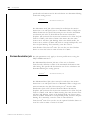
Motion Direct Command Verification
When you select Execute from a Motion Direct Command dialog, the
operands are verified. If any operand fails verification, an error
message “Failed to Verify” is displayed on the dialog and a detailed
error message is displayed in the error result window describing the
fault indicating the instance of Motion Direct Command that the
results apply to. This allows multiple verification errors to be
displayed and provides navigation to the error source, that is, double
clicking the error in the results window will navigate to the
appropriate Motion Direct Command dialog.
If no errors are detected during verification, then nothing is displayed.
Publication LOGIX-UM002B-EN-P - January 2007
Test an Axis with Motion Direct Commands
41
Motion Direct Command Execution Error
When you select Execute from a Motion Direct Command dialog and
the operands are verified as valid, then the command is executed. If
the command fails immediately, then an error message “Execution
Error” is displayed on the dialog. Whether or not an error is detected,
a detailed message is displayed to the Error result window describing
the immediate results of the executed command.
The message “Execution Error” is cleared on subsequent command
execution or if a new command is selected from the command list.
The information pumped to the Error result window after an
execution is not cleared. This allows for a history of what has been
executed from a given instance of the Motion Direct Command dialog.
Publication LOGIX-UM002B-EN-P - January 2007
42
Test an Axis with Motion Direct Commands
What If the Software Goes
Offline or the Controller
Changes Modes?
If RSLogix 5000 software transitions to offline, Hard Program mode
(PROG), or Hard Run mode (RUN), then any executing Direct
Command instruction continues execution and the Execute button is
disabled.
Can Two Workstations Give
Motion Direct Commands?
Whenever the Execute button is enabled and commands can be
executed from a workstation, the group is locked. This means that
another workstation cannot execute commands while this lock is in
place. The lock stays in place until the workstation executing
commands relinquishes the lock.
Publication LOGIX-UM002B-EN-P - January 2007
Chapter
3
Handle Faults
Introduction
The controller has these types of motion faults.
Type
Description
Example
Instruction error
Caused by a motion instruction:
• Instruction errors do not impact controller operation.
• Look at the error code in the motion control tag to see
why an instruction has an error.
• Fix instruction errors to optimize execution time and
make sure that your code is accurate
A Motion Axis Move (MAM)
instruction with a parameter out of
range
Fault
Caused by a problem with the servo loop:
• You choose whether or not motion faults give the
controller major faults.
• Can shutdown the controller if you do not correct the
fault condition
• Loss of feedback
• Actual position exceeding an
overtravel limit
To handle motion faults:
• Choose If Motion Faults Shut Down the Controller
• Choose the Fault Actions for an Axis
• Set the Fault Action for an Axis
43
Publication LOGIX-UM002B-EN-P - January 2007
44
Handle Faults
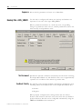
Choose If Motion Faults
Shut Down the Controller
Action
By default, the controller keeps running when there is a motion fault.
As an option, you can have motion faults cause a major fault and shut
down the controller.
Details
1. Choose a General Fault Type.
Do you want any motion fault to cause a major fault and shut down the controller?
• YES — Choose Major Fault.
• NO — Choose Non-Major Fault. You must write code to handle motion faults.
2. Set the General Fault Type.
A.
B.
C.
D.
Publication LOGIX-UM002B-EN-P - January 2007
Handle Faults
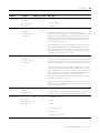
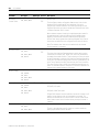
Choose the Fault Actions
for an Axis
45
Use the fault actions to set how an axis responds to different types of
faults. The type of faults depends on the type of axis and how you
configure it.
If you want to
Then choose
Description
Shutdown the axis and let it
coast to a stop
Shutdown
Shutdown is the most severe action. Use it for faults that could endanger the
machine or the operator if you don’t remove power quickly and completely.
For this axis type When the fault happens
AXIS_SERVO
• Axis servo action is disabled.
• The servo amplifier output is zeroed.
• The appropriate drive enable output is deactivated.
• The OK contact of the servo module opens. Use this
to open the E-Stop string to the drive power supply.
AXIS_SERVO_DRIVE
• Axis servo action and drive power structure are
immediately disabled.
• The axis coasts to a stop unless you use some form of
external braking.
Disable the axis and let the drive Disable Drive
stop the axis using it's best
available stopping method
For this axis type When the fault happens
AXIS_SERVO
• Axis servo action is disabled.
• The servo amplifier output is zeroed.
• The appropriate drive enable output is deactivated.
AXIS_SERVO_DRIVE
• The drive switches to local servo loop control and the
axis is slowed to a stop using the Stopping Torque.
• If the axis doesn’t stop in the Stopping Time, the
servo action and the power structure are disabled.
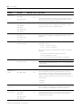
Leave the servo loop on and stop Stop Motion
the axis at its Maximum
Deceleration rate
Use this fault action for less severe faults. It is the gentlest way to stop. Once the
axis stops, you must clear the fault before you can move the axis. The exception is
Hardware Overtravel and Software Overtravel faults, where you can jog or move
the axis off the limit.
For this axis type When the fault happens
AXIS_SERVO
AXIS_SERVO_DRIVE
The axis slows to a stop at the Maximum Deceleration Rate
without disabling servo action or the servo module’s Drive
Enable output.
• Control of the drive’s servo loop is maintained.
• The axis slows to a stop at the Maximum
Deceleration rate without disabling the drive.
Write your own application code Status Only
to handle the fault
Use this fault action only when the standard fault actions are not appropriate.
With this fault action, you must write code to handle the motion faults. For Stop
Motion or Status Only, the drive must stay enabled for the controller to continue to
control the axis. Selecting Status Only only lets motion continue if the drive itself is
still enabled and tracking the command reference.
Publication LOGIX-UM002B-EN-P - January 2007
46
Handle Faults
Set the Fault Action for an
Axis
1.
2.
3.
4.
Publication LOGIX-UM002B-EN-P - January 2007
Use the following steps to set the fault actions for an axis.
Chapter
4
Create and Configure a Coordinate System
Introduction
In RSLogix 5000 software a coordinate system is a grouping of one or
more primary and/or ancillary axes that you must create to generate
coordinated motion. You can configure the coordinate system with
one, two, or three dimensions. RSLogix 5000 software supports these
types of geometry:
• Cartesian
• Articulated Dependent
• Articulated Independent
The Coordinate System tag is used to set the attribute values to be
used by the Multi-Axis Coordinated Motion instructions in your
motion applications. The Coordinate System tag must exist before you
can run any of the Multi-Axis Coordinated Motion instructions. This is
where you introduce the COORDINATE_SYSTEM data type, associate
the Coordinate System to a Motion Group, associate the axes to the
Coordinate System, set the dimension, and define the values later used
by the operands of the Multi-Axis Motion Instructions. The values for
Coordination Units, Maximum Speed, Maximum Acceleration,
Maximum Deceleration, Actual Position Tolerance, and Command
Position Tolerance are all defined by the information included when
the Coordinate System tag is configured. This chapter describes how
to name, configure, and edit your Coordinate System tag.
47
Publication LOGIX-UM002B-EN-P - January 2007
48
Create and Configure a Coordinate System
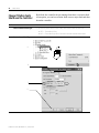
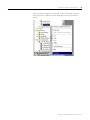
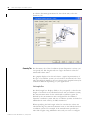
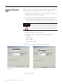
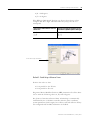
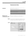
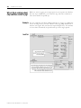
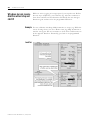
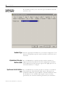
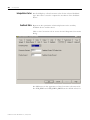
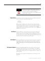
Create a Coordinate System
To create a coordinate system, right click the motion group in the
Controller Organizer and select New Coordinate System.
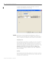
The New Tag dialog opens.
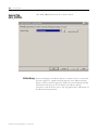
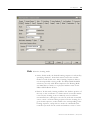
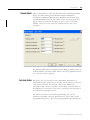
Enter Tag Information
A tag lets you allocate and reference data stored in the controller. A
tag can be a single element, array, or a structure. With
COORDINATE_SYSTEM selected as the Data Type, there are only two
types of tags that you can create.
• A base tag lets you create your own internal data storage.
• An alias tag lets you assign a name of your choosing to an
existing coordinate system tag.
Publication LOGIX-UM002B-EN-P - January 2007
Create and Configure a Coordinate System
49
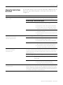
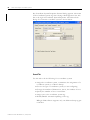
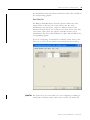
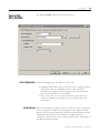
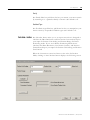
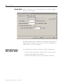
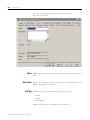
New Tag Parameters
The following parameters appear on the New Tag dialog when you
are creating a base tag or an alias tag.
Make entries in the following fields.
Field
Entry
Name
Type a name for the coordinate system tag.
The name can have a maximum of 40 characters
containing letters, numbers and underscores (_).
Description
Type a description for your motion axis for annotation
purposes.
This field is optional.
Type
Click on the radio button for the type of tag to create.
The only valid choices are Tag and Alias. Selecting either
Produced or Consumed generates an error when the OK
button is pressed.
Alias For
This field displays only when Alias is selected for Tag
Type. Enter the name of the related Base Tag.
Data type
Enter COORDINATE_SYSTEM.
Scope
A Coordinate System tag can be created only at the
controller scope.
Style
This field cannot be edited.
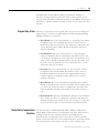
Name
Enter a relevant name for the new tag. The name can be up to 40
characters and can be composed of letters, numbers, or underscores
(_).
Description
Enter a description of the tag. This is an optional field and is used for
annotating the tag.
Type
For a Coordinate System you may choose either Base or Alias for the
Tag Type. Click on the appropriate radio button for the type of tag
you are creating.
• Base refers to a normal tag (selected by default).
Publication LOGIX-UM002B-EN-P - January 2007
50
Create and Configure a Coordinate System
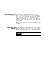
• Alias refers to a tag that references another tag with the same
definition. Special parameters appear on the New Tag dialog
that allow you to identify to which base tag the alias refers.
Alias For:
If you selected Alias as the Tag Type the Alias For: field displays. Enter
the name of the associated Base Tag.
Data Type
In the Data Type field select COORDINATE_SYSTEM if you entered
from either method that did not fill this field automatically.
Scope
Enter the Scope for the tag. A Coordinated System Tag can only be
Controller Scope.
Style
The Style parameter is not activated. No entry for this field is possible.
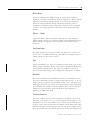
After the information for the tag is entered, you have two options. You
can either press the OK button to create the tag or you can press the
Configure Button located next to the Data Type field to use the
Wizard screens to enter the values for the Coordinate System Tag.
Pressing the OK button, creates the tag and automatically places it in
the Ungrouped Axes folder or the Motion Group if the tag was
initiated from the Motion Group menu.
Pressing the Configure button next to the Data Type field invokes the
Coordinate System Tag Wizard to let you continue to configure the
Coordinate System tag.
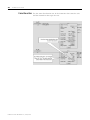
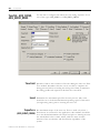
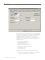
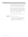
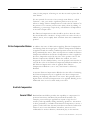
Coordinate System Wizard Screens The Coordinate System Wizard screens walk you through the process
of configuring a Coordinate System. These are the same screens that
appear when you access Coordinate System Properties but instead of
appearing as tabbed screens, they advance you through the process
by individual screens. At the bottom of each screen, is a series of
buttons. To advance to the next screen click on the Next button and
the information you entered is saved and you advance to the next
wizard screen. To end your progression through the wizard screens
click on the Finish button. The information entered to this point is
saved and the coordinate System is stored in the Controller Organizer
Publication LOGIX-UM002B-EN-P - January 2007
Create and Configure a Coordinate System
51
under either the Ungrouped Axes folder or the Motion Group (if a
motion group has been associated with the coordinate system).
It is not necessary to use the wizard screens to configure your
coordinate System. Once it has been created, you can access the
Coordinate System Properties screen and enter the information for the
coordinate System. See the section entitled “Editing Coordinate System
Properties” later in this manual for detailed information about entering
configuration information.
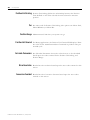
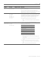
General Wizard Screen
The General screen lets you:
• associate the tag to a Motion Group.
• enter the Coordinate System type.
• select the Dimension for the tag (that is, the number of
associated axes).
• specify the number of dimensions to transform.
• enter the associated axis information.
• select whether or not to update Actual Position values of the
Coordinate System automatically during operation.
This screen has the same fields as the General tab found under
Coordinate System Properties.
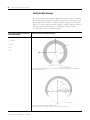
Geometry Wizard Screen
The Geometry screen lets you configure key attributes related to
non-Cartesian geometry and shows the bitmap of the associated
geometry.
Offsets Wizard Screen
The Offset screen lets you configure the offsets for the base and end
effector. This screen shows the bitmaps for the offsets related to the
geometry.
Units Wizard Screen
The Units screen lets you determine the units that define the
coordinate system. At this screen you define the Coordination Units
and the Conversion Ratios. This screen has the same fields as the
Units tab found under Coordinate System Properties.
Publication LOGIX-UM002B-EN-P - January 2007
52
Create and Configure a Coordinate System
Dynamics Wizard Screen
Use the Dynamics screen for entering the Vector values used for
Maximum Speed, Maximum Acceleration, and Maximum Deceleration.
It is also used for entering the Actual and Command Position
Tolerance values. This screen has the same fields as the Dynamics tab
found under Coordinate System Properties.
Manual Adjust Button
The Manual Adjust button is inactive when creating a Coordinate
System tag via the wizard screens. It is active on the Dynamics tab of
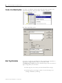
the Coordinate System Properties screen. It is described in detail in the
“Editing Coordinate System Properties” later in this chapter.
Tag Wizard Screen
The Tag screen lets you rename your Tag, edit your description and
review the Tag Type, Data Type, and Scope information.
The only fields that you can edit on the Tag screen are the Name and
Description fields. These are the same fields as on the New Tag screen
and the Coordinate System Properties Tag tab.
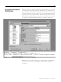
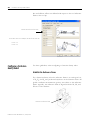
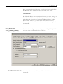
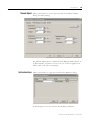
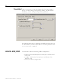
Edit Coordinate System
Properties
Create your Coordinate System in the New Tag window, then
configure it. If you did not use the Wizard screens available from the
Configure button on the New Tag screen, you can make your
configuration selections from the Coordinate System Properties screen.
You can also use the Coordinate System Properties screens to edit an
existing Coordinate System tag. These have a series of tabs that access
a specific dialog for configuring the different facets of the Coordinate
System. Make the appropriate entries for each of the fields. An asterisk
appears on the tab to indicate changes have been made but not
implemented. Press the Apply button at the bottom of each dialog to
save your selections.
TIP
Publication LOGIX-UM002B-EN-P - January 2007
When you configure your Coordinate System, some
fields may be unavailable (dimmed) because of
choices you made in the New Tag window.
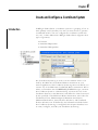
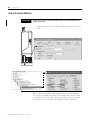
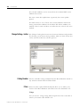
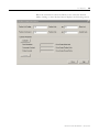
Create and Configure a Coordinate System
53
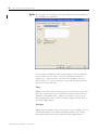
In the Controller Organizer, right-click on the coordinate system to
edit and select Coordinate System Properties from the pull-down
menu.
Publication LOGIX-UM002B-EN-P - January 2007
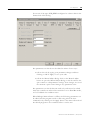
54
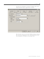
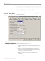
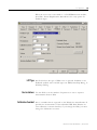
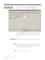
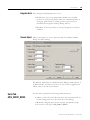
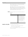
Create and Configure a Coordinate System
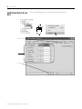
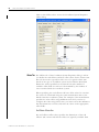
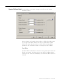
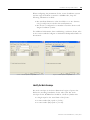
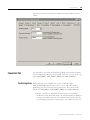
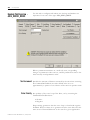
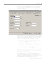
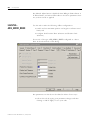
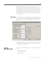
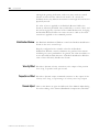
The Coordinate System Properties General dialog appears. The name
of the Coordinate System tag that is being edited appears in the title
bar to the right of Coordinate System Properties. The General tab
dialog for a Cartesian coordinate system is shown below.
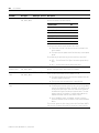
General Tab
Use this tab to do the following for a coordinate system:
• Assign the coordinate system, or terminate the assignment of a
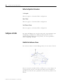
coordinate system, to a Motion Group.
• Choose the type of coordinate system you are configuring.
• Change the number of dimensions, that is, the number of axes.
• Specify the number of axes to transform.
• Assign axes to the coordinate system tag.
• Enable/Disable automatic updating of the tag.
RSLogix 5000 software supports only one Motion Group tag per
controller.
Publication LOGIX-UM002B-EN-P - January 2007
Create and Configure a Coordinate System
55
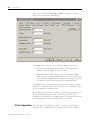
Motion Group
Selects and displays the Motion Group to which the Coordinate
System is associated. A Coordinate System assigned to a Motion Group
appears in the Motion Groups branch of the Controller Organizer,
under the selected Motion Group sub-branch. Selecting <none>
terminates the Motion Group association, and moves the coordinate
system to the Ungrouped Axes sub-branch of the Motions Groups
branch.
Ellipsis (…) button
Opens the Motion Group Properties dialog box for the Assigned
Motion Group, where you can edit the Motion Group properties. If no
Motion Group is assigned to this coordinate system, this button is
dimmed.
New Group button
The New Group button opens the New Tag dialog box, where you
can create a new Motion Group tag. This button is enabled only if no
Motion Group tag has been created.
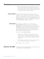
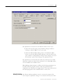
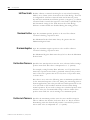
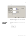
Type
Selects and displays the type of coordinate system (robot type) in the
Motion Group. Available choices are Cartesian, Articulated Dependent
and Articulated Independent. The type of coordinate system you
choose in this field changes the configuration tabs that are available.
Dimension
Enter the coordinate system dimensions, that is, the number of axes,
that this coordinated system is to support. The options are 1, 2, or 3 in
keeping with its support of a maximum of three axes. Changes in the
Dimension spin box also reflect in the Axis Grid by either expanding
or contracting the number of fields available. Data is set back to the
defaults for any axis that is removed from the Axis Grid due to
reducing the Dimension field.
Transform Dimension
Enter the number of axes in the coordinate system that you want to
transform. The options are 1, 2, or 3 in keeping with its support of a
maximum of 3 axes. The number of axes that you transform must be
equal to or less than the specified coordinate system dimensions. The
transform function always begins at the first axis. For example, if you
have specified that the coordinate system has 3 axes but indicate only
Publication LOGIX-UM002B-EN-P - January 2007
56
Create and Configure a Coordinate System
that 2 axes be transformed, then axes 1 and 2 will be transformed. In
other words, you cannot specify that only axes number 2 and number
3 be transformed.
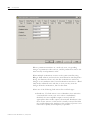
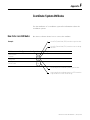
Axis Grid
The Axis Grid is where you associate axes to the Coordinate System.
There are five columns in the Axis Grid that provide information
about the axes in relation to the Coordinate System.
[] (Brackets)
The Brackets column displays the indices in tag arrays used with
the current coordinate system. The tag arrays used in multi-axis
coordinated motion instructions map to axes using these indices.
Coordinate
The text in this column X1, X2, or X3 (depending on the entry to
the Dimension field) is used as a cross reference to the axes in
the grid. For a Cartesian system the mapping is simple.
Axis Name
The Axis Name column is a list of combo boxes (the number is
determined by the Dimension field) used to assign axes to the
coordinate system. The pull-down lists display all of the Base
Tag axes defined in the project. (Alias Tag axes do not display in
the pull down list.) They can be axes associated with the motion
group, axes associated with other coordinated systems, or axes
from the Ungrouped Axes folder. Select an axis from the
pull-down list. The default is <none>. It is possible to assign
fewer axes to the coordinate system than the Dimension field
allows; however, you will receive a warning when you verify
the coordinate system and if left in that state, the instruction
generates a run-time error. You can assign an axis only once in
a coordinate system. Ungrouped axes also generate a runtime
error.
Ellipsis Button (...)
The Ellipsis buttons in this column take you to the Axis
Properties pages for the axis listed in the row. See the “Creating
and Configuring Your Motion Axis” chapter in this manual for
information about the Axis Properties page.
Publication LOGIX-UM002B-EN-P - January 2007
Create and Configure a Coordinate System
57
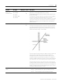
Coordination Mode
The Coordination Mode column indicates the axes that are used
in the velocity vector calculations. If the type of coordinate
system is specified as Cartesian, then Primary axes are used in
these calculations. For non-Cartesian coordinate systems the
coordination mode for the axes defaults to Ancillary.
Enable Coordinate System Auto Tag Update
The Enable Coordinate System Auto Tag Update checkbox lets you
determine whether or not the Actual Position values of the current
coordinated system are automatically updated during operation. Click
on the checkbox to enable this feature. The Coordinate System Auto
Tag Update feature can ease your programming burden if you would
need to add GSV statements to the program in order to get the desired
result. However, by enabling this feature the Coarse Update rate is
increased. Whether to use the Coordinate System Auto Tag Update
feature depends upon the trade-offs between ease in programming
and increase in execution time. Some users may want to enable this
feature in the initial programming of their system to work out the
kinks and then disable it and enter the GSV statements to their
program to lower their execution time.
Note: Enabling this feature may result in some performance
penalty.
Press Apply to implement your entries or cancel to not save the new
entries.
Publication LOGIX-UM002B-EN-P - January 2007
58
Create and Configure a Coordinate System
To edit the Geometry parameters for the robotic arm, select the
Geometry tab.
Geometry Tab The Geometry tab of the Coordinate System Properties is where you
can specify the link lengths and zero angle orientation values for
articulated robotic arms.
The graphic displayed on this tab shows a typical representation of
the type of coordinate system you selected on the General tab. Your
robot should look similar to the one shown in the graphic but may be
somewhat different depending on your application.
Link Lengths Box
The Link Length box displays fields to let you specify a value for the
length of each link in an articulated robotic arm (coordinate system).
The measurement units for the articulated coordinate system are
defined by the measurement units configured for the affiliated
Cartesian coordinate system. The two coordinate systems are linked or
affiliated with each other by an MCT instruction.
When specifying the link length values be sure that the values are
calculated using the same measurement units as the linked Cartesian
coordinate system. For example, if the manufacturer specifies the
robot link lengths using millimeter units and you want to configure
Publication LOGIX-UM002B-EN-P - January 2007
Create and Configure a Coordinate System
59
the robot using inches, then you must convert the millimeter link
measurements to inches and enter the values in the appropriate link
length fields.
IMPORTANT
Be sure that the link lengths specified for an
articulated coordinate system are in the same
measurement units as the affiliated Cartesian
coordinate system. Your system will not work
properly if you are using different measurement
units.
The number of fields available for configuration in the link lengths
box is determined by values entered on the General tab for the type
of coordinate system, total coordinate system dimensions and
transform dimensions. The link identifiers are L1 and L2 in the
corresponding graphic. These fields are not configurable for a
Cartesian coordinate system.
Zero Angle Orientations Box
The zero-angle orientation is the rotational offset of the individual
joint axes. If applicable, enter the offset value in degrees for each joint
axis. The number of available fields is determined by the coordinate
dimension value entered on the General tab. The angle identifiers are
Z1, Z2, and Z3 in the corresponding graphic.
Publication LOGIX-UM002B-EN-P - January 2007
60
Create and Configure a Coordinate System
To edit the Units properties, select the Units tab to access the
Coordinate System Properties Units dialog.
Units Tab The Units tab of the Coordinate System Properties is where you
determine the units that define the coordinate system. This screen is
where you define the Coordination Units and the Conversion Ratios.
Coordination Units
The Coordination Units field lets you define the units to be used for
measuring and calculating motion related values such as position,
velocity, and the like. The coordination units do not need to be the
same for each coordinate system. Enter units that are relevant to your
application and maximize ease of use. When you change the
Coordination Units, the second portion of the Coordination Ratio
Units automatically changes to reflect the new units. Coordination
Units is the default.
Axis Grid
The Axis Grid of the Units dialog displays the axis names associated
with the Coordinate System, the conversion ratio, and the units used
to measure the conversion ratio.
Publication LOGIX-UM002B-EN-P - January 2007
Create and Configure a Coordinate System
61
Axis Name
The Axis Name column contains the names of the axes assigned
to the Coordinate System in the General screen. These names
appear in the order that they were configured into the current
coordinate system. This column is not editable from this screen.
Conversion Ratio
The Conversion Ratio column defines the relationship of axis
position units to coordination units for each axis. For example: If
the position units for an axis is in millimeters and the axis is
associated with a coordinate system whose units are in inches,
then the conversion ratio for this axis/coordinate system
association is 25.4/1 and can be specified in the appropriate row
of the Axis Grid.
The numerator can be entered as a float or an integer. The
denominator must be entered as an integer only.
Conversion Ratio Units
The Conversion Ratio Units column displays the axis position
units to coordination units used. The Axis Position units are
defined in the Axis Properties – Units screen and the
coordination units are defined in Coordinated System Properties
– Units screen. These values are dynamically updated when
changes are made to either axis position units or coordination
units.
Click on the Apply button to preserve your edits or Cancel to discard
your changes.
Publication LOGIX-UM002B-EN-P - January 2007
62
Create and Configure a Coordinate System
Click on the Offsets tab to access the Coordinate System Properties
Offset dialog.
Offsets Tab The Offsets tab of the Coordinate System Properties dialog is where
you define the end effector and base offset values for the robotic arm.
This tab shows the top and/or sides view of a typical robotic arm
based on the type of coordinate system and coordinate Transform
dimension values specified on the General tab. The number of
available offset fields in each box is determined by the number of
axes associated with the coordinate system.
When specifying the end effector and base offset values be sure that
the values are calculated using the same measurement units as the
linked Cartesian coordinate system. For example, if the manufacturer
specifies the robot offset using millimeter units and you want to
configure the robot using inches then, you must convert the millimeter
link measurements to inches and enter the values in the appropriate
offset fields.
End Effector Offsets Box
The end effector offset value specifies the dimensions of the end
effector. The correct end effector offsets are typically available from
Publication LOGIX-UM002B-EN-P - January 2007
Create and Configure a Coordinate System
63
the manufacturer. The end effector indicators are X1e, X2e, and X3e in
the corresponding graphic.
Base Offsets Box
The RSLogix 5000 Kinematics internal equations define the robot
origin relative to the first joint of the robotic arm. The robot
manufacturer may specify the origin at a different location. The
difference between these two locations is the base offsets value. The
correct base offset values are typically available from the robot
manufacturer. The base offset indicators are X1b, X2b and X3b in the
corresponding graphic.
If you are configuring an articulated coordinate system, click on the
Joints tab to access the Coordinate System Properties Joints dialog.
Joints Tab The Joints tab is only accessible if you are configuring or editing an
articulated coordinate system. This screen is where you define the
Publication LOGIX-UM002B-EN-P - January 2007
64
Create and Configure a Coordinate System
Joint Conversion Ratios. Joint axis units are always specified in
Degrees.
Axis Name
The Axis Name column displays the names of the axes associated to
the coordinate system. The names appear in the order that they were
configured into the coordinate system. This is a read-only field.
Joint Ratio
The Joint Ratio column (shown in white) is divided into two columns
that define the relationship between the axis position units to the joint
axis units. The left-half of the Joint Ratio column is a configurable field
that lets you specify a value for the axis position units (numerator).
The right-half of the Joint Ratio column is a configurable field that lets
you specify a value for the joint axis units (denominator). Keep in
mind that Joint axis units are always specified as degrees.
Joint Units
The Joint Units column is a read-only field that displays the configured
axis position units to the joint units. The Axis Position units are
defined in the Axis Properties – Units dialog. Joint units are always
defined as Degrees.
Publication LOGIX-UM002B-EN-P - January 2007
Create and Configure a Coordinate System
65
If you are configuring a Cartesian coordinate system, click on the
Dynamics tab to access the Coordinate System Properties Dynamics
dialog.
Dynamics Tab The Dynamics dialog is accessible only if you are configuring a
Cartesian Coordinate System. The Dynamics tab is for entering the
Vector values used for Maximum Speed, Maximum Acceleration, and
Maximum Deceleration. It is also used for entering the Actual and
Command Position Tolerance values.
Vector Box
In the Vector box, values are entered for Maximum Speed, Maximum
Acceleration, and Maximum Deceleration and are used by the
Coordinated Motion instructions in calculations when their operands
are expressed as percent of Maximum. The Coordination Units to the
right of the edit boxes automatically change when the coordination
units are redefined at the Units dialog.
Publication LOGIX-UM002B-EN-P - January 2007
66
Create and Configure a Coordinate System
Maximum Speed
Enter the value for Maximum Speed to be used by the
Coordinated Motion instructions in calculating vector speed
when speed is expressed as a percent of maximum.
Maximum Acceleration
Enter the value for Maximum Acceleration to be used by the
Coordinated Motion instructions to determine the acceleration
rate to apply to the coordinate system vector when acceleration
is expressed as a percent of maximum.
Maximum Deceleration
Enter the value for Maximum Deceleration to be used by the
Coordinated Motion instructions to determine the deceleration
rate to apply to the coordinate system vector when deceleration
is expressed as a percent of maximum. The Maximum
Deceleration value must be a nonzero value to achieve any
motion using the coordinate system.
Position Tolerance Box
In the Position Tolerance Box, values are entered for Actual and
Command Position Tolerance values. See the Logix5000 Motion
Instruction Set Reference Manual, publication number 1756-RM007,
for more information regarding the use of Actual and Command
Position Tolerance.
Actual
Enter the value in coordination units, for Actual Position to be
used by Coordinated Motion instructions when they have a
Termination Type of Actual Tolerance.
Command
Enter the value in coordination units, for Command Position to
be used by Coordinated Motion instructions when they have a
Termination Type of Command Tolerance.
Manual Adjust Button
The Manual Adjust button on the Coordinate System Dynamics tab
accesses the Manual Adjust Properties dialog. The Manual Adjust
button is enabled only when there are no pending edits on the
properties dialog.
Publication LOGIX-UM002B-EN-P - January 2007
Create and Configure a Coordinate System
67
Dynamics Tab Manual Adjust At this dialog you can make changes to the Vector and Position
Tolerance values.
These changes can be made either online or offline. The blue arrows
to the right of the fields indicate that they are immediate commit
fields. This means that the values in those fields are immediately
updated to the controller if online or to the project file if offline.
Reset Button
The Reset Button reloads the values that were present at the time this
dialog was entered. The blue arrow to the right of the Reset button
means that the values are immediately reset when the Reset button is
clicked.
Publication LOGIX-UM002B-EN-P - January 2007
68
Create and Configure a Coordinate System
Tag Tab The Tag tab is for reviewing your Tag information and renaming the
tag or editing the description.
Use this tab to modify the name and description of the coordinate
system. When you are online, all of the parameters on this tab
transition to a read-only state, and cannot be modified. If you go
online before you save your changes, all pending changes revert to
their previously-saved state.
Name
Displays the name of the current tag. You can rename the tag at this
time. The name can be up to 40 characters and can include letters,
numbers, and underscores (_). When you rename a tag, the new
name replaces the old one in the Controller Organizer after click on
the OK or Apply button.
Description
Displays the description of the current tag, if any is available. You can
edit this description. The edited description replaces the existing
description when you click on either the OK or Apply button.
Publication LOGIX-UM002B-EN-P - January 2007
Create and Configure a Coordinate System
69
Tag Type
Indicates the type of the current Coordinate System tag. This type may
be:
• Base
• Alias
The field is not editable and is for informational purposes only.
Data Type
Displays the data type of the current Coordinate System tag, which is
always COORDINATE_SYSTEM. This field cannot be edited and is for
informational purposes only.
Scope
Displays the scope of the current Coordinate System tag. The scope
for a Coordinate System tag can be only controller scope. This field is
not editable and is for informational purposes only.
Publication LOGIX-UM002B-EN-P - January 2007
70
Create and Configure a Coordinate System
Publication LOGIX-UM002B-EN-P - January 2007
Chapter
5
Inhibit an Axis
Introduction
Use this chapter to block the controller from using an axis.
When to Inhibit an Axis
Use the following information to determine when to inhibit an axis.
You want to block the controller from using an
axis because the axis is faulted or not installed.
You want to let the controller use the other
axes.
Example 1
Suppose you make equipment that has between 8 and 12 axes,
depending on which options your customer buys. In that case, set up
one project for all 12 axes. When you install the equipment for a
customer, inhibit those axes that the customer didn’t buy.
Example 2
Suppose you have two production lines that use the same SERCOS
ring. And suppose one of the lines gets a fault. In that case, inhibit the
axes on that line. This lets you run the other line while you take care
of the fault.
71
Publication LOGIX-UM002B-EN-P - January 2007
72
Inhibit an Axis
Before You Begin
Before you inhibit or uninhibit an axis,
turn off all of the axes.
Before you inhibit or uninhibit an axis:
1. Stop all motion.
2. Open the servo loops of all the axes. Use an instruction such as the Motion Servo Off
(MSF) instruction.
This lets you stop motion under your control. Otherwise the axes turn off on their own when
you inhibit or uninhibit one of them.
The connections to the motion module shut down
when you inhibit or uninhibit an axis.
This opens the servo loops of all the axes that are connected to
the module. For a SERCOS interface module, the SERCOS ring
also shuts down.
SERCOS Ring
Controller
Drive
Motor
Drive
Motor
Motion Module
SERCOS Ring
The controller automatically restarts the connections. The SERCOS ring also phases back up.
Inhibit only certain types of axes.
You can inhibit only these types of axes:
• AXIS_SERVO
• AXIS_SERVO_DRIVE
• AXIS_GENERIC_DRIVE
Publication LOGIX-UM002B-EN-P - January 2007
Inhibit an Axis
To inhibit all of the axes of a motion
module, inhibit the module instead.
73
Do you want to inhibit all of the axes of a motion module?
• YES — Inhibit the motion module instead.
• NO — Inhibit the individual axes.
It’s OK to inhibit all of the axes of a module one-by-one. It’s just easier to inhibit the module.
Example: Suppose your motion module has two axes and you want to inhibit both of those
axes. In that case, just inhibit the module.
If you inhibit all of the axes on a SERCOS ring, the drives phase up to phase 2. This happens
whether you inhibit all the axis individually or you inhibit the motion module.
Phase
2
Phase
2
Drive
Drive
Inhibited
Motion
Module
Motion
Module
Phase
2
Phase
2
Inhibited
Drive
Drive
Inhibited
Publication LOGIX-UM002B-EN-P - January 2007
74
Inhibit an Axis
Do you have 1394 drives on a SERCOS
ring?
!!
"#
$%
&&&
Publication LOGIX-UM002B-EN-P - January 2007
'
'
'
'
Inhibit an Axis
75
Example: Inhibit an Axis
1. Make sure all axes are off.
This axis is off.
And this axis is off.
All axes are off.
2. Use a one-shot instruction to trigger the inhibit.
Your condition to inhibit
the axis is on.
Your condition to
uninhibit the axis is off.
All axes are off.
Give the command to inhibit the
axis.
3. Inhibit the axis.
The inhibit command
turns on.
Inhibit this axis.
Inhibit the axis.
4. Wait for the inhibit process to finish.
All of these have happened:
• The axis is inhibited.
• All uninhibited axes are ready.
• The connections to the motion module are running again.
• For a SERCOS ring, the SERCOS ring has phased up again.
What you want to do next
Publication LOGIX-UM002B-EN-P - January 2007
76
Inhibit an Axis
Example: Uninhibit an Axis
1. Make sure all axes are off.
This axis is off.
And this axis is off.
All axes are off.
2. Use a one-shot instruction to trigger the uninhibit.
Your condition to
uninhibit the axis is on.
Your condition to inhibit
the axis is off.
All axes are off.
Give the command to uninhibit
the axis.
3. Uninhibit the axis.
The uninhibit command
turns on.
Uninhibit this axis.
Uninhibit the axis.
4. Wait for the inhibit process to finish.
All of these have happened:
• The axis is uninhibited.
This axis is on.
• All uninhibited axes are ready.
• The connections to the motion module are running again.
• For a SERCOS ring, the SERCOS ring has phased up again.
Publication LOGIX-UM002B-EN-P - January 2007
This axis is OK to run.
Chapter
6
Kinematics in RSLogix 5000 Software
Introduction
This chapter provides you with the information you need when using
the Kinematics functionality within RSLogix 5000 software. This
chapter also provides you with guidelines for robot-specific
applications.
Overview of Kinematics
Functionality in RSLogix
5000 Software
RSLogix 5000 software provides built-in Kinematics transformation
capability for controlling non-Cartesian robots. The Kinematics
function provides seamless transformation of Cartesian coordinates to
Joint coordinates enabling the movement of rotating bases, elbows,
and shoulders found in robotic arms. The benefits of RSLogix 5000
Kinematics integrated motion includes:
• Implementation of both sequential and robot-arm control within
one controller.
• No synchronization or handshake code required to link the
robot arm to the controller.
• All data is available via the controller resulting in one HMI for
both the controller and robot arm.
• Consistent hardware solution that reduces the need for spare
parts and operator training.
You program the RSLogix 5000 Kinematics function by using the
standard motion instruction set in RSLogix 5000 software and these
instructions:
• Motion Coordinated Transform (MCT)
• Motion Calculate Transform Position (MCTP)
The MCT instruction binds two coordinate systems and establishes a
coordinate transformation between two coordinate systems. After the
MCT instruction is configured and executed you can program the
77
Publication LOGIX-UM002B-EN-P - January 2007
78
Kinematics in RSLogix 5000 Software
robotic arm in the Cartesian coordinate system or the Joint coordinate
system.
Any Motion
Instruction
(Source)
(Cartesian)
(Virtual)
Coordinate
System 1
(CS1)
MCT
Instruction
Coordinate
System 2
(CS2)
Any Motion
Instruction
(Target)
(Joint)
(Machine)
The MCTP instruction is a calculate instruction that transforms a
specified position from the source coordinate system into the target
coordinate system and vice versa. This instruction can also be used for
position recovery and teach position routines.
The RSLogix 5000 integrated Kinematics function provides you with
an easy-to-use interface for:
• Forward Kinematics - Joint space coordinates are transformed to
Cartesian space coordinates.
• Inverse Kinematics - Cartesian coordinates are transformed to
Joint space coordinates.
In RSLogix 5000 software Cartesian space is typically configured by
using virtual axes and Joint space is usually configured by using real
axes
Robot geometries supported for two and three axes are:
• Cartesian
• Articulated Dependant
• Articulated Independent
Three-axes Selective Compliant Assembly Robot Arm (SCARA)
geometry is supported by leveraging the Articulated Independent
geometry configuration.
Publication LOGIX-UM002B-EN-P - January 2007
Kinematics in RSLogix 5000 Software
Useful Terms
79
Understanding the terms used in this chapter enables you to properly
configure your robot.
Term
Definition
Forward Kinematics
The solution of source positions given the target positions. In practice this would be computing the
Cartesian positions given the Joint positions.
Forward Transform
The solution of source positions given target positions.
Inverse Kinematics
The solution of joint positions given Cartesian positions. Typically, converts Cartesian positions to joint
positions.
Inverse Transform
The solution of target positions given source positions.
Joint axis
A rotary robotic coordinate axis typically having overtravel rather than rollover limits.
Kinematics
The family of mathematical equations that convert positions back and forth between two linked geometries.
Orientation
Robotic term for directional attitude or rotation about a point in Cartesian (3D) space. Orientation is
expressed as three ordered rotations around the X, Y, and Z Cartesian axes.
Reference frame
An imaginary Cartesian coordinate system used to define a Cartesian origin and reference orientation.
Source system
One of two coordinate systems used in a Kinematics transform and having special properties. When
connected to a target system by means of a Kinematics transform, motion commanded at the source
system’s inputs produces motion at both the source and target system’s outputs (if the physical axes are
connected).
Target system
One of two coordinate systems used in a Kinematics transform and having special properties. When
connected to a source system by means of a Kinematics transform, motion commanded at the target
system’s inputs produces motion in both the source and target system’s outputs (if the physical axes are
connected).
Transform
General term for conversion equations which map values in one coordinate space to values in another
coordinate space.
Translation
Robotic term for a linear movement or offset in Cartesian (3 dimensional) space. Translation describes the
distance between two Cartesian points.
Zero Angle Offset
Offset on a rotary axis in the Joint Coordinate system between where the Kinematics equations were
derived and where you want your zero position to be.
Gather Information about
Your Robot
Before you begin the configuration steps for the Kinematics
transformation function you need to gather specific information about
your robot and application parameters. Specifications for your robot
can be found in the documentation provided by the manufacturer
while other required information is application dependent. Before you
begin configuring the RSLogix 5000 Kinematics for motion control you
should know:
•
•
•
•
•
•
•
Robot geometry type
Zero angle orientation
Work envelope
Link lengths
Base offsets
End-effector offsets
Arm solution
Publication LOGIX-UM002B-EN-P - January 2007
80
Kinematics in RSLogix 5000 Software
Summary of Kinematic
Steps
After you create a Joint (target) coordinate system tag for your Motion
control project there are general steps to follow for Kinematics.
1. Determine and then configure the type of coordinate system you
need for your robot. Refer to page 82.
2. Establish the Joint-to-Cartesian reference frame relationship. For
more information regarding the Joint-to-Cartesian reference
frame, refer to the section about the type of robot you are using.
WARNING
The correct relationship between the Joint reference frame and
the Cartesian reference frame must be established. Failure to
do this can allow your robot to move to unexpected positions
causing machine damage and/or injury or death to personnel.
3. Identify your robot work envelope.
4. Determine and then configure the following parameters,
including:
• Link lengths
• Base offsets
• End-effector offsets
5. Create the source and target coordinate systems.
Typical Cartesian Coordinate System Configuration for Articulated
Independent robot.
Typical Joint Coordinate System Configuration for an Articulated
Independent robot.
6. Save the project.
Publication LOGIX-UM002B-EN-P - January 2007
Kinematics in RSLogix 5000 Software
81
7. Download the Kinematic project to the 1756-L6xx controller and
then, use the MCT instruction to link the Joint coordinate system
to the Cartesian coordinate system.
The Joint-to-Cartesian reference frame relationship is
automatically established by the 1756-L6xx controller after the
Joint coordinate system parameters (link lengths, base offsets
and end-effector offsets) are configured and the MCT instruction
is enabled. For additional information about the MCT or MCTP
instructions refer to the LOGIX5000 Controllers Motion
Instructions, publication 1756-RM007H-EN-P.
For detailed steps about Creating and Configuring a Coordinate
System, refer to Chapter 4.
Publication LOGIX-UM002B-EN-P - January 2007
82
Kinematics in RSLogix 5000 Software
Determine the Coordinate
System Type
If your robot looks similar to
Your Coordinate System type is
Articulated Independent
For configuration information go to page 84.
Articulated Dependent
For configuration information go to page 94.
Publication LOGIX-UM002B-EN-P - January 2007
Kinematics in RSLogix 5000 Software
If your robot looks similar to
83
Your Coordinate System type is
Cartesian
This illustration shows a typical Gantry machine.
For configuration information go to page 102.
Cartesian
Sliding Member
This illustration shows a typical H-bot.
For configuration information go to page 103.
X2 Axis
TCP
X1 Axis
Sliding rail
Stationary Rails
Stationary Motors A
Stationary Motors B
Articulated Independent
This illustration shows a typical SCARA.
For configuration information go to page 106.
Publication LOGIX-UM002B-EN-P - January 2007
84
Kinematics in RSLogix 5000 Software
Configure an Articulated
Independent Robot
Use these guidelines when configuring an Articulated Independent
robot.
WARNING
Before turning ON the Transform and/or establishing the
reference frame, be sure to do the following for the joints of the
target coordinate system:
• set and enable the soft travel limits.
• enable the hard travel limits.
Failure to do this can allow the robot to move outside of the
work envelope causing machine damage and/or serious injury
or death to personnel.
Establish the Reference Frame
The reference frame is the Cartesian coordinate frame that defines the
origin and the three primary axes (X1, X2, and X3). These axes are
used to measure the real Cartesian positions.
WARNING
Failure to properly establish the correct reference frame for
your robot can cause the robotic arm to move to unexpected
positions causing machine damage and/or injury or death to
personnel.
The reference frame for an Articulated Independent robot is located at
the base of the robot as shown in the figure below.
Figure 1 - Articulated Independent
Before you begin establishing the Joint-to-Cartesian reference frame
relationship, it is important to know some information about the Kine-
Publication LOGIX-UM002B-EN-P - January 2007
Kinematics in RSLogix 5000 Software
85
matic mathematical equations used in the ControlLogix 1756-L6xx
controllers. The equations were written as if the Articulated Independent robot joints were positioned as shown in Figure 2 - Articulated
Independent.
• +J1 is measured counterclockwise around the +X3 axis starting
at an angle of J1=0 when J1 is aligned with the X1 axis.
• +J2 is measured counterclockwise starting with J2=0 when J2 is
parallel to X1-X2 plane.
• +J3 is measured counterclockwise with J3=0 when J3 is aligned
with link L1.
Figure 2 - Articulated Independent
Side View
When your robot is physically in the
position illustrated in
The RSLogix 5000 Actual Position
tags for the axes must read as
Figure 2 - Articulated Independent
J1 = 0
J2 = 0
J3 = 0
Figure 3 - Articulated Independent
J1 = 0
J2 = 90
J3 = -90
Publication LOGIX-UM002B-EN-P - January 2007
86
Kinematics in RSLogix 5000 Software
Figure 3 - Articulated Independent
Side View
If your robot’s physical position and joint angle values can not match
those shown in Figure 2 - Articulated Independent or Figure 3 Articulated Independent then use one of the Alternate Methods for
Establishing the Joint-to-Cartesian reference frame relationship.
Alternate Methods for Establishing the Reference Frame
The following methods let you establish a reference frame for an
Articulated Independent robot.
For each
Use one of these methods to establish the reference frame
Incremental axis
Each time the robot’s power is cycled.
Absolute axis
Only when you establish absolute home.
• Method 1 - establishes a Zero Angle Orientation and allows the
configured travel limits and home position on the joint axes to
remain operational. Use this method if you are operating the
axes between the travel limits determined prior to programming
a Motion Redefine Position (MRP) instruction and want these
travel limits to stay operational.
• Method 2 - uses a MRP instruction to redefine the axes position
to align with the Joint reference frame. This method may require
the soft travel limits to be adjusted to the new reference frame.
Method 1 - Establishing a Reference Frame
Each axis for the robot has the mechanical hard stop in each of the
positive and negative directions. Manually move or press each axes of
Publication LOGIX-UM002B-EN-P - January 2007
Kinematics in RSLogix 5000 Software
87
the robot against its associated mechanical hard stop and redefine it to
the hard limit actual position provided by the robot manufacturer. J1 is
the axis at the base of the robot that rotates around X3.
When the robot is moved so that Link1 is parallel to the X3 axis and
Link2 is parallel to X1 axis as shown in Figure 2 - Articulated
Independent, the RSLogix 5000 Actual Position tag values should be
equal to:
• J1 = 0
• J2 = 90 degrees
• J3 = -90 degrees
If the RSLogix 5000 Positions tags do not correspond to these values,
configure the Zero Angle Orientation for the joint(s) that do not
correspond.For example:
If the RSLogix 5000 software read-out
values are
Set the Zero Angle Orientations on the
Coordinate System Properties dialog to
J1 = 10
Z1 = -10
J2 = 80
Z2 = 10
J3 = -85
Z3 = -5
The Joint-to-Cartesian reference frame relationship is automatically
established by the 1756-L6xx controller after the Joint coordinate
system parameters (link lengths, base offsets and end-effector offsets)
are configured and the MCT instruction is enabled.
Set the Zero Angle Orientations
Publication LOGIX-UM002B-EN-P - January 2007
88
Kinematics in RSLogix 5000 Software
Method 2 - Establishing a Reference Frame
Position the robot so that:
• Link1 is parallel to the X3 axis.
• Link2 is parallel to X1 axis.
Program a MRP instruction for all three axes with the following values:
• J1 = 0
• J2 = 90 degrees
• J3 = -90 degrees
The Joint-to-Cartesian reference frame relationship is automatically
established by the 1756-L6xx controller after the Joint coordinate
system parameters (link lengths, base offsets and end-effector offsets)
are configured and the MCT instruction is enabled.
Identify the Work Envelope
The work envelope is the three dimensional region of space that
defines the reaching boundaries for the robot arm. The work
envelope for an articulated robot is ideally a complete sphere having
an inner radius equal to L1- L2 and outer radius equal to L1+L2. Due
to the range of motion limitations on individual joints, the work
envelope may not be a complete sphere.
Publication LOGIX-UM002B-EN-P - January 2007
Kinematics in RSLogix 5000 Software
If the range-of-motion values for the
articulated robot are
89
Typically, the work envelope would be
J1 = ± 170
J2 = 0 to 180
J3 = ± 100
L1= 10
L2 = 12
Top view - Depicts the envelope of the tool center point sweep in J1 and J3 while J2 remains
at a fixed position of 0 degrees.
Side view - Depicts the envelope of the tool center point sweep in J2 and J3 while J1 remains
at a fixed position of 0 degrees.
Publication LOGIX-UM002B-EN-P - January 2007
90
Kinematics in RSLogix 5000 Software
Define the Configuration Parameters
RSLogix 5000 software can be configured for control of robots with
varying reach and payload capacities. As a result, it is very important
to know the configuration parameter values for your robot including:
• Link lengths
• Base offsets
• End-effector offsets
The configuration parameter information is available from the robot
manufacturer.
IMPORTANT
Be sure that the values for the link lengths, base offsets and
end-effector offsets are entered into the Configuration
Parameters dialog using the same measurement units.
The following example illustrates the typical configuration parameters
for an Articulated Independent robot.
X3
L2 = 12 inches
X1e = 2 inches
X3e2 = 1.5 inches
-X3e1 = 3.0 inches
L1 = 12 inches
Tool reference frame
X3b = 4.0 inches
Robot Origin
X1b = 3.0 inches
X3e = -X3e1 + X3e2
X3e = -3 + 1.5
X3e = -1.5 inches
If the robot is two dimensional, then X3b and X3e would be X2b and X2e respectively.
Figure 4 - Articulated Independent
Publication LOGIX-UM002B-EN-P - January 2007
Kinematics in RSLogix 5000 Software
91
Link Lengths
Link lengths are the rigid mechanical bodies attached at joints.
For an articulated independent robot with
The length of
Is equal to the value of the distance between
2 dimensions
L1
J1 and J2
L2
J2 and the end-effector
L1
J2 and J3
L2
J3 and the end-effector
3 dimensions
Enter the Link Length values.
For the robot shown in Figure 4 - Articulated Independent, the
Link Length values are:
• L1 = 10.0
• L2 = 12.0
Base Offsets
The base offset is a set of coordinate values the redefines the origin of
the robot. The correct base offset values are typically available from
Publication LOGIX-UM002B-EN-P - January 2007
92
Kinematics in RSLogix 5000 Software
the robot manufacturer. Enter the values for the base offsets in the
X1b and X3b fields of the Coordinate System Properties dialog.
Enter the Base Offset values
For the robot shown in our example, the Base Offset values are:
• X1b = 3.0
• X3b = 4.0
End-Effector Offsets
The robot can have an end-effector attached to the end of robot link
L2. If there is an attached end-effector then you must configure the
end-effector offset value on the Coordinate System Properties dialog.
The end-effector offsets are defined with respect to the tool reference
frame at the tool tip.
Some robots also have an offset defined for the J3 joint as illustrated in
the robot example (refer to on page 90). You can account for this
value when computing the X3e end-effector offset value. In the value
Publication LOGIX-UM002B-EN-P - January 2007
Kinematics in RSLogix 5000 Software
93
for X3e offset is entered as the sum of X3e1+X3e2 (-3+1.5 = -1.5). The
configured value for X3e is -1.5.
Enter the end-effector offset values.
For the robot shown in our example, the end-effector values are:
• X1e = 2.0
• X3e = -1.5
Publication LOGIX-UM002B-EN-P - January 2007
94
Kinematics in RSLogix 5000 Software
Configure an Articulated
Dependent Robot
The Articulated Dependent robot has motors for the elbow and the
shoulder located at the base of the robot. The dependent link controls
J3 at the elbow. Use these guidelines when configuring an Articulated
Dependent robot.
WARNING
Before turning ON the Transform and/or establishing the
reference frame, be sure to do the following for the joints of the
target coordinate system:
• set and enable the soft travel limits.
• enable the hard travel limits.
Failure to do this can allow the robot to move outside of the
work envelope causing machine damage and/or serious injury
or death to personnel.
Establish the Reference Frame
The reference frame is the Cartesian (typically the source) coordinate
frame that defines the origin and the three primary axes (X1, X2 and
X3). These are used to measure the real Cartesian positions.
WARNING
Failure to properly establish the correct reference frame for
your robot can cause the robotic arm to move to unexpected
positions causing machine damage and/or injury or death to
personnel.
The reference frame for an Articulated Dependent robot is at the base
of the robot as shown in the figure below.
Figure 1 - Articulated Dependent
Before you begin establishing the Joint-to-Cartesian reference frame
relationship, it is important to know some information about how the
Publication LOGIX-UM002B-EN-P - January 2007
Kinematics in RSLogix 5000 Software
95
Kinematic mathematical equations in the ControlLogix 1756-L6xx
controllers were written. The equations were written as if the
Articulated-dependent robot joints were positioned as shown in
Figure 2 - Articulated Dependent.
• +J1 is measured counterclockwise around the +X3 axis starting
at an angle of J1=0 when J1 is aligned with the X1 axis.
• +J2 is measured counterclockwise starting with J2=0 when J2 is
parallel to X1-X2 plane.
• +J3 is measured counterclockwise with J3=0 when J3 is parallel
to the X1-X2 plane.
Side View
X3
X1
Figure 2 - Articulated Dependent
When your robot is physically in the
position illustrated in
The RSLogix 5000 Actual Position
tags for the axes must read as
Figure 2 - Articulated Dependent
J1 = 0
J2 = 0
J3 = 0
Figure 3 - Articulated Dependent
J1 = 0
J2 = 90
J3 = 0
.
Side View
Figure 3 - Articulated Dependent
Publication LOGIX-UM002B-EN-P - January 2007
96
Kinematics in RSLogix 5000 Software
If your robot’s physical position and joint angle values can not match
those shown in Figure 2 - Articulated Dependent or in Figure 3 Articulated Dependent then, use one of the methods outlined in this
section to establish the Joint-to-Cartesian reference frame relationship.
WARNING
Failure to properly establish the correct reference frame for
your robot can cause the robotic arm to move to unexpected
positions potentially resulting in damage to property or injury to
personnel.
Alternate Methods for Establishing the Reference Frame
The following methods let you establish a reference frame for an
Articulated Independent robot.
For each
Use one of these methods to establish the reference frame
Incremental axis
Each time the robot’s power is cycled.
Absolute axis
Only when you establish absolute home.
• Method 1 - establishes a Zero Angle Orientation and allows the
configured travel limits and home position on the joint axes to
remain operational. Use this method if you are operating the
axes between the travel limits determined prior to programming
a Motion Redefine Position (MRP) instruction and want these
travel limits to stay operational.
• Method 2 - uses a Motion Redefine Position (MRP) instruction to
redefine the axes position to align with the Joint reference
frame. This method may require the soft travel limits to be
adjusted to the new reference frame.
Method 1 - Establishing a Reference Frame
Each axis for the robot has the mechanical hard stop in each of the
positive and negative directions. Manually move or press each axes of
the robot against its associated mechanical hard stop and redefine it to
the hard limit actual position provided by the robot manufacturer. J1 is
the axis at the base of the robot that rotates around X3.
When the robot is moved so that Link1 is parallel to the X3 axis and
Link2 is parallel to X1 axis as shown in Figure 3 - Articulated
Dependent, the RSLogix5000 values for the Actual Position tags
should be:
• J1 = 0
Publication LOGIX-UM002B-EN-P - January 2007
Kinematics in RSLogix 5000 Software
97
• J2 = 90 degrees
• J3 = 0 degrees
If the RSLogix 5000 Actual Position tags do not show these values,
configure the Zero Angle Orientation for the joint(s) that do not
correspond.
If the RSLogix 5000 software read-out
values are
Set the Zero Angle Orientations on the
Coordinate System Properties dialog to
J1 = 10
J2 = 80
J3 = 5
Z1 = -10
Z2 = 10
Z3 = -5
Set the Zero Angle Orientations
Method 2 - Establishing a Reference Frame
Position the robot so that:
• L1 is parallel to the X3 axis.
• L2 is parallel to X1 axis.
Program a Motion Redefine Position (MRP) instruction for all the three
axis to with the following values 0, 90, and 0 degrees.
The Joint-to-Cartesian reference frame relationship is automatically
established by the 1756-L6xx controller after the Joint coordinate
system parameters (link lengths, base offsets, and end-effector offsets)
are configured and the MCT instruction is enabled.
Publication LOGIX-UM002B-EN-P - January 2007
98
Kinematics in RSLogix 5000 Software
Identify the Work Envelope
The work envelope is the three-dimensional region of space defining
the reaching boundaries for the robot arm. The work envelope of an
articulated robot is ideally a complete sphere having an inner radius
equal to |L1- L2| and outer radius equal to |L1+L2|. However, due to
the range of motion limitations on individual joints, the work
envelope may not be a complete sphere.
If the range-of-motion values for the
articulated robot are
Typically, the work envelope would be
J1 = ± 170
J2 = 0 to 180
J3 = ± 60
L1= 10
L2 =12
Top view - Depicts the envelope of the tool center point sweep in J1 and J3 while J2 remains at a
fixed position of 0 degrees.
Side view - Depicts the envelope of the tool center
point sweep in J2 and J3 while J1 remains at a fixed position of 0 degrees.
Publication LOGIX-UM002B-EN-P - January 2007
Kinematics in RSLogix 5000 Software
99
Define Configuration Parameters
RSLogix 5000 software can be configured for control of robots with
varying reach and payload capacities. As a result, it is very important
to know the configuration parameter values for your robot including:
• Link lengths
• Base offsets
• End-effector offsets
The configuration parameter information is available from the robot
manufacturer.
IMPORTANT
Be sure that the values for the link lengths, base offsets and
end-effector offsets are entered into the Configuration
Parameters dialog using the same measurement units.
The following example illustrates the typical configuration parameters
for an articulated dependent robot.
X3
L1 = 10 inches
L2 = 12 inches
X1e = 2 inches
-X3e1 = 3.0 inches
Tool reference frame
X3b = 4.0 inches
Robot Origin
X1b = 3.0 inches
If the robot is two-dimensional, then X3b and X3e would be X2b and X2e respectively.
Figure 4 - Articulated Dependent
Publication LOGIX-UM002B-EN-P - January 2007
100
Kinematics in RSLogix 5000 Software
Link Lengths
Link lengths are the rigid mechanical bodies attached at joints.
For an articulated dependent robot with
The length of
Is equal to the value of the distance
between
two dimensions
L1
J1 and J2
L2
J2 and the end-effector
L1
J2 and J3
L2
J3 and the end-effector
three dimensions
Enter the Link Length values.
For the robot shown in our example, the Link Length values are:
• L1 = 10.0
• L2 = 12.0
Base Offsets
The base offset is a set of coordinate values the redefines the origin of
the robot. The correct base-offset values are typically available from
Publication LOGIX-UM002B-EN-P - January 2007
Kinematics in RSLogix 5000 Software
101
the robot manufacturer. Enter the values for the base offsets in the
X1b and X3b fields of the Coordinate System Properties dialog.
Enter the Base Offset values
For the robot shown in our example, the Base Offset values are:
• X1b = 3.0
• X3b = 4.0
End-Effector Offsets
The robot can have an end-effector attached to the end of robot link
L2. If there is an attached end-effector then you must configure the
end-effector offset value on the Coordinate System Properties dialog.
Publication LOGIX-UM002B-EN-P - January 2007
102
Kinematics in RSLogix 5000 Software
The end-effector offsets are defined with respect to the tool reference
frame at the tool tip.
Enter the end-effector offset values.
For the robot shown in our example, the end-effector values are:
• X1e = 2.0
• X3e = -3.0
Configure a Cartesian
Gantry Robot
Use these guidelines when configuring a Cartesian Gantry robot.
Establish the Reference Frame
For a Cartesian Gantry robot the reference frame is an orthogonal set
of X1, X2, and X3 axes positioned anywhere on the Cartesian robot. All
global coordinate measurements (points) are relative to this reference
frame. Typically, the reference frame is aligned with the X1, X2, and
X3 axes of the machine.
Cartesian XYZ reference frame
Publication LOGIX-UM002B-EN-P - January 2007
Kinematics in RSLogix 5000 Software
103
To establish a Local coordinate system with axes positions different
from the reference frame, use the Motion Redefine Position (MRP)
instruction to reset the position register. You can also use the Offset
Vector in the MCT transform instruction to establish an offset between
the Local coordinate system and the reference frame.
For more information about Motion Instructions, refer to the
Logix5000 Controllers Motion Instruction Reference manual,
publication number 1756-RM007.
Identify the Work Envelope
The work envelope for a Cartesian Gantry robot is typically a solid
rectangle of length, width and height that is equal to the axis travel
limits.
Define Configuration Parameters
Link Lengths
Does not apply to a Cartesian Gantry robot configuration.
Base Offsets
Does not apply to a Cartesian Gantry robot configuration.
End-Effector Offsets
Does not apply to a Cartesian Gantry robot configuration.
Configure a Cartesian H-bot
The H-bot is a special type of Cartesian two-axis gantry robot. This
type of machine has three rails positioned in the form of a letter H.
Two motors are positioned at the end of each leg of the robot. Unlike
Publication LOGIX-UM002B-EN-P - January 2007
104
Kinematics in RSLogix 5000 Software
a standard gantry robot, neither motor is riding on top of the moving
rails. Use these guidelines when configuring a Cartesian H-bot.
Sliding Member
X2 X2 Virt
X1
TCP
X1 Virt
Sliding rail
Stationary Rails
Stationary Motors A
Stationary Motors B
In the Cartesian H-bot illustration above, the X1 and X2 axes are the
real axes on the robot. X1 Virt and X2 Virt are configured as the virtual
axes.
The configuration of the H-bot mechanical linkages enable it to move
at a 45-degree angle to the axes when either motor A or motor B is
rotated.
For example, when:
• Motor A (X1 axis) is rotated, the robot move along a straight line
at + 45 degree angle.
• Motor B (X2 axis) is rotated the machine moves at an angle of -45
degrees.
• Motors A and B are both rotated clockwise at the same speed
then, the machine moves along a horizontal line.
• Motors A and B are both rotated counterclockwise at the same
speed then, the machine moves along a vertical line.
Any X,Y position can be reached by properly programming the two
motors.
For example, a move of (X1 = 10, X2 = 0) causes the X1X2 axes to
move to a position of (X1=7.0711, X2=7.0711). A move to (X1=10, X2
=10) causes the robot to move to a position of (X1=0, X2=14.142).
While this configuration might be very confusing for a programmer,
utilizing the RSLogix 5000 software Kinematics function configured
Publication LOGIX-UM002B-EN-P - January 2007
Kinematics in RSLogix 5000 Software
105
with two Cartesian coordinate systems and a -45 degree rotation easily
performs the function.
To configure two Cartesian coordinate systems, Coordinate system 1
(CS1) and Coordinate system 2 (CS2), each containing two linear axes,
use the following steps.
1. Configure CS1 to contain the virtual X1 and X2 axes.
2. Configure CS2 to contain the real X1 and X2 axes.
3. Configure the Orientation vector of the MCT instruction as (0,0,
-45) a negative degree rotation around the X3 axis.
4. Configure the Translation vector as (0, 0, 0).
5. Link the CS1 and CS2 using a MCT instruction.
6. Home the H-bot and then program all moves in CS1.
The machine moves the tool center point (TCP) to the programmed
coordinates in CS2. The -45 degree rotation introduced by the
Kinematics, counteracts the 45 degree rotation introduced by the
mechanics of the machine and the H-bot moves to the CS1 configured
coordinates. As a result, a programmed move of X1virt=10, X2virt=5 moves to
a real mechanical position of X1=10, X2=5.
Establish the Reference Frame
For a Cartesian H-bot the Base Coordinate system is an orthogonal set
of X1, X2 axes postponed anywhere on the Cartesian H-bot. The
angular rotation of the reference frame may not be rotated for this
robot since the angular rotation vector is used to achieve the
45-degree rotation required for the mechanical operation.
Identify the Work Envelope
The work envelope for a Cartesian H-bot is a rectangle of length and
width equal to the axis soft travel limits.
Publication LOGIX-UM002B-EN-P - January 2007
106
Kinematics in RSLogix 5000 Software
Define Configuration Parameters
Link Lengths
Does not apply to a Cartesian H-bot configuration.
Base Offsets
Does not apply to a Cartesian H-bot configuration.
End-Effector Offsets
Does not apply to a Cartesian H-bot configuration.
Configure a SCARA
The typical SCARA has two revolute joints and a single prismatic joint.
Configuring a SCARA robot in RSLogix 5000 software, uses the
Articulated Independent two-axis geometry. Use these guidelines
when configuring a SCARA.
Establish the Reference Frame
The reference frame for the SCARA geometry is at the base of link L1.
The J1 axis rotates around the X3 axis. When J1 is at zero degrees, L1
is along the X1 axis. J2 is a revolute joint whose axis of rotation is
parallel to the X3 axis. J3 is a prismatic axis that moves parallel to the
X3 axis.
Publication LOGIX-UM002B-EN-P - January 2007
Kinematics in RSLogix 5000 Software
107
When configuring the parameters for the source Coordinate system
and the target Coordinate system for a SCARA robot, keep the
following information in mind:
• The transform dimension value should be set to two because
only J1 and J2 are involved in the transformations.
• The Z axis is configured as a member of both the Source and
Target Coordinate systems.
For additional information about establishing a reference frame, refer
to the section entitled Configure an Articulated Independent Robot in
this manual.
Source Coordinate System Configuration
Target Coordinate System Configuration
Identify the Work Envelope
The work envelope is the three dimensional region of space that
defines the reaching boundaries for the robot arm. The work
envelope for the SCARA robot should be a hollow cylinder with:
• a height equal to the travel limit of the J3 axis.
• an inner radius (R1) equal to |L1-L2|.
• an outer radius (R2) equal to |L1+L2|.
Publication LOGIX-UM002B-EN-P - January 2007
108
Kinematics in RSLogix 5000 Software
Define Configuration Parameters
RSLogix 5000 software can be configured for control of robots with
varying reach and payload capacities. As a result, it is very important
to know the configuration parameter values for your robot including:
• Link lengths
• Base offsets
• End-effector offsets
The configuration information is available from the robot
manufacturer.
IMPORTANT
Publication LOGIX-UM002B-EN-P - January 2007
Be sure that the values for the link lengths, base offsets and
end-effector offsets are entered into the Configuration
Parameters dialog using the same measurement units.
Kinematics in RSLogix 5000 Software
109
The following example illustrates the typical configuration parameters
for a SCARA robot.
L1= 10
L2= 8
Figure 1 - SCARA
Link Lengths
Link lengths are the rigid mechanical bodies attached at joints.
Enter the Link Length values.
For the robot shown in Figure 1 - SCARA, the Link Length values
are:
• L1 = 10
• L2 = 8
Base Offsets
Base offsets do not apply to a SCARA robot configuration.
End-Effector Offsets
End-effector offsets do not apply to a SCARA robot configuration.
Publication LOGIX-UM002B-EN-P - January 2007
110
Kinematics in RSLogix 5000 Software
Arm Solutions
A Kinematic arm solution is the position of all joints on the robot that
correspond to a Cartesian position. When the Cartesian position is
inside the workspace of the robot then at least one solution will
always exist. Many of the geometries have multiple joint solutions for
a single Cartesian position.
• Two-axis robots - two joint solutions typically exist for a
Cartesian position.
• Three-axis robots - four joint solutions typically exist for a
Cartesian position.
Left-Arm and Right-Arm
Solutions for Two-Axes
Robots
A robot having an arm configuration has two Kinematics solutions
when attempting to reach a given position (point A shown on the
figure below). One solution satisfies the equations for a right-armed
robot, the other solution satisfies the equations for a left-armed robot.
Left-Arm Solution
Right-Arm Solution
Right-Arm and Left-Arm Solutions
Solution Mirroring for
Three-Dimensional Robots
For a three-dimensional Articulated Independent robot there are four
possible solutions for the same point.
•
•
•
•
Left-Arm
Right-Arm
Left-Arm Mirror
Right-Arm Mirror
For example, consider the Cartesian point XYZ (10,0,15). The joint
position corresponding to this point has four joint solutions. Two of
the solutions are the same as the solutions for the two dimensional
Publication LOGIX-UM002B-EN-P - January 2007
Kinematics in RSLogix 5000 Software
111
case. The other two solutions are mirror image solutions where J1 is
rotated 180 degrees.
Right-Arm
Right-Arm Mirror
J3
J3
J2
J2
Left-Arm Mirror
Left-Arm
J3
J3
J2
J2
Activating Kinematics
WARNING
Be sure to choose an arm solution before activating the
Kinematic function. Failure to do so can result in machine
damage and/or serious injury or death to personnel.
Before activating Kinematics the robot should be in a left-arm or
right-arm solution. The robot stays in the same configuration in which
it was activated as it is moved in Cartesian or source coordinate mode.
If activated in a fully-extended-arm mode (this is neither a left-arm nor
a right-arm solution), the system chooses a left-arm solution.
Publication LOGIX-UM002B-EN-P - January 2007
112
Kinematics in RSLogix 5000 Software
Change the Robot Arm
Solution
You can switch the robot from a left-arm solution to a right-arm
solution or vice versa. This is done automatically when a joint move is
programmed forcing a left/right change to occur. After the change is
performed the robot stays in the new arm solution when Cartesian
moves are made. The robot arm solution changes again (if required)
when another joint move is made.
Example: Suppose, you want to move the robot from position A
(x1,y1) to position B (X2,Y2) (refer to figure below). At position A the
system is in a left arm solution. Programming a Cartesian move from A
(X1,Y1) to B (X2,Y2) means that the system moves along the straight
line (refer to illustration) from A to B while maintaining a left arm
solution. If you want to be at position B in a right-arm solution, you
must make a joint move in J1 from θ1 to θ2 and a joint move in J2
from α1 to α2.
Plan for Singularity
A singularity occurs when an infinite number of joint positions
(mathematical solutions) exist for a given Cartesian position. The
Cartesian position of a singularity is dependent on the type of the
robot geometry and the size of the link lengths for the robot. Not all
robot geometries have singularity positions.
For example, singularities for an Articulated Independent robot occur
when:
• the robot manipulator folds its arm back onto itself and the
Cartesian position is at the origin.
• the robot is fully stretched at or very near the boundary of its
workspace.
Publication LOGIX-UM002B-EN-P - January 2007
Kinematics in RSLogix 5000 Software
113
An error condition is generated when a singularity position is reached.
WARNING
Encounter a No-solution
Position
WARNING
Avoid programming your robot towards a singularity position
when programming in Cartesian mode. The velocity of the robot
increases very rapidly as it approaches a singularity position
and can result in injury or death to personnel.
Avoid programming your robot towards a no solution position
when programming in Cartesian mode. The velocity of the robot
increases very rapidly as it approaches this position and can
result in injury or death to personnel.
When a robot is programmed to move beyond its work envelope,
there is no mathematical joint position for the programmed Cartesian
position. The system forces an error condition.
For example, if an Articulated Independent robot has two 10-inch
arms, the maximum reach is 20 inches. Programming to a Cartesian
position beyond 20 inches produces a condition where no
mathematical joint position exists.
Error Conditions
Kinematics error conditions are detected:
• upon activation of a transformation by executing a MCT
instruction.
• in some movement conditions.
Errors can occur for certain movement conditions for either the
source or target coordinate system after a transformation has
been established. These type of errors are reported in the MCT
instruction error codes. Singularity and other movement error
conditions are also reported in the MCT error codes.
• computing an invalid position via an MCTP instruction.
For a list and description of error codes, refer to the LOGIX5000
Controllers Motion Instructions, publication 1756-RM007H-EN-P.
Publication LOGIX-UM002B-EN-P - January 2007
114
Kinematics in RSLogix 5000 Software
Monitor Status Bits for Kinematics
You can monitor the status of the Kinematics functions using RSLogix
5000 software status bits.
To see if
Check the following tag
And this bit
For
A coordinate system is the source of an active transform
Coordinate system
TransformSourceStatus
On
A coordinate system is the target of an active transform
Coordinate system
TransformTargetStatus
On
An axis is part of an active transform
Axis
TransformStateStatus
On
An axis is moving because of a transform
Axis
ControlledByTransformStatus
On
Publication LOGIX-UM002B-EN-P - January 2007
Chapter
7
Interpret Module Lights (LEDs)
Introduction
Use this chapter to interpret the lights on the front of your module.
1756-M02AE Module
For This Module
See Page
1756-M02AE Module
115
1756-M02AS Module
117
1756-HYD02 Module
120
SERCOS interface Module
123
OK Light
2 AXIS SERVO
CH 0
CH 1
FDBK
FDBK
DRIVE
DRIVE
OK
State
Description
Off
The module is not operating.
Recommended Action
• Apply chassis power.
• Verify the module is completely inserted into the chassis
and backplane.
Flashing green
Steady green
The module has passed internal diagnostics, but it is
not communicating axis data over the backplane.
• Axis data is being exchanged with the
module.
• None, if you have not configured the module.
• If you have configured the module, check the slot number
in the 1756-M02AE Properties dialog box.
None. The module is ready for action.
• The module is in the normal operating state.
Flashing red
Solid red
• A major recoverable failure has occurred.
• Check the servo fault word for the source of the error.
• A communication fault, timer fault, or NVS
update is in progress.
• Clear the fault condition using the motion instructions.
• The OK contact has opened.
• If the flashing persists, reconfigure the module.
• A potential non-recoverable fault has
occurred.
• The OK contact has opened.
115
• Resume normal operation.
• Reboot the module.
• If the solid red persists, replace the module.
Publication LOGIX-UM002B-EN-P - January 2007
116
Interpret Module Lights (LEDs)
FDBK Light
State
Description
Off
The axis is not used.
Recommended Action
• None, if you are not using this axis.
• If you are using this axis, make sure you configured the
module and associated an axis tag with the module.
Flashing green
The axis is in the normal servo loop inactive state.
None. You can change the servo axis state by executing motion
instructions.
Steady green
The axis is in the normal servo loop active state.
None. You can change the servo axis state by executing motion
instructions.
Flashing red
The axis servo loop error tolerance has been
exceeded.
• Correct the source of the problem.
• Clear the servo fault using a fault reset instruction.
• Resume normal operation.
Solid red
An axis encoder feedback fault has occurred.
• Correct the source of the problem by checking the
encoder and power connections.
• Clear the servo fault using the MAFR instruction.
• Resume normal operation.
DRIVE Light
State
Off
Description
• The axis is not used.
• The axis is a position-only axis type.
Recommended Action
• None, if you are not using the axis or have configured it
as a position-only axis.
• Otherwise, make sure you have configured the module,
associated an axis tag with the module, and configured
the axis as a servo axis.
Flashing green
The axis drive is in the normal disabled state.
None. You can change the servo axis state by executing a
motion instruction.
Steady green
The axis drive is in the normal enabled state.
None. You can change the servo axis state by executing a
motion instruction.
Flashing red
The axis drive output is in the Shutdown state.
• Check for faults that may have generated this state.
• Execute the shutdown reset motion instruction.
• Resume normal operation.
Solid red
The axis drive is faulted.
• Check the drive status.
• Clear the drive fault condition at the drive.
• Execute a fault reset motion instruction.
• Resume normal operation.
• Check the configuration for the Drive Fault.
• If configured to be normally open and there is no
voltage, this is the normal condition.
• If configured to be normally closed and there is 24V
applied, this is the normal condition.
Publication LOGIX-UM002B-EN-P - January 2007
Interpret Module Lights (LEDs)
1756-M02AS Module
117
OK Light
2 AXIS SERVO / SSI
CH0
CH1
FDBK
FDBK
DRIVE
DRIVE
OK
State
Description
Off
The module is not operating.
Recommended Action
• Apply chassis power.
• Verify the module is completely inserted in chassis and
backplane.
Flashing green
The module has passed internal diagnostics, but it is
not communicating axis data over the backplane.
None, if you have not configured the module.
If you have configured the module, check the slot number in the
1756-M02AS Properties dialog box.
Steady green
One of the following:
None
• Module is exchanging axis data.
• The module is in the normal operating state.
Flashing red
One of the following:
• A major recoverable failure has occurred.
• A communication fault, timer fault, or
non-volatile memory storage (NVS) update is
in progress.
• The OK contact has opened.
If an NVS update is in progress, complete the NVS update.
If an NVS update is not in progress:
• Check the Servo Fault word for the source of the error.
• Clear the servo fault condition via Motion Axis Fault
Reset instruction.
• Resume normal operation.
• If the flashing persists, reconfigure the module.
Steady red
One of the following:
• A potential non- recoverable fault has
occurred.
Reboot the module.
• The OK contact has opened.
If the solid red persists, replace the module.
Publication LOGIX-UM002B-EN-P - January 2007
118
Interpret Module Lights (LEDs)
FDBK Light
State
Description
Recommended Action
Off
The axis is not used.
None, if you are not using this axis.
If you are using this axis, make sure the module is configured
and an axis tag has been associated with the module.
Flashing green
The axis is in the normal servo loop inactive state.
None. The servo axis state can be changed by executing motion
instructions.
Steady green
The axis is in the normal servo loop active state.
None. The servo axis state can be changed by executing motion
instructions.
Flashing red
The axis servo loop error tolerance has been
exceeded.
• Correct the source of the problem.
• Clear the servo fault condition using the Motion Axis
Fault Reset instruction.
• Resume normal operation.
Steady red
An axis SSI feedback fault has occurred.
• Correct the source of the problem by checking the SSI
device and power connections.
• Clear the servo fault condition using the Motion Axis
Fault Reset instruction.
• Resume normal operation.
Publication LOGIX-UM002B-EN-P - January 2007
Interpret Module Lights (LEDs)
119
DRIVE Light
State
Description
Off
One of the following:
• The axis is not used.
• The axis is a position- only axis type.
Recommended Action
None, if the axis is not used or is a position- only type.
Otherwise, make sure the module is configured, an axis tag has
been associated with the module, and the axis type is servo.
Flashing green
The axis drive is in the normal disabled state.
None. The servo axis state can be changed by executing motion
instructions.
Steady green
The axis drive is in the normal enabled state.
None. The servo axis state can be changed by executing motion
instructions.
Flashing red
The axis drive output is in the shutdown state.
• Check for faults that may have generated this state.
• Execute the Motion Axis Shutdown Reset instruction.
• Resume normal operation.
Steady red
The axis drive is faulted.
• Check the drive status.
• Clear the Drive Fault condition at the drive.
• Clear the servo fault condition using the Motion Axis
Fault Reset instruction.
• Resume normal operation.
• Check the configuration for the Drive Fault.
• If configured to be normally open and there is no voltage,
this is the normal condition.
• If configured to be normally closed and 24V dc is applied,
this is the normal condition.
Publication LOGIX-UM002B-EN-P - January 2007
120
Interpret Module Lights (LEDs)
1756-HYD02 Module
OK Light
HYDRAULIC
AX0
AX1
FDBK
FDBK
DRIVE
DRIVE
OK
State
Description
Off
The module is not operating.
Recommended Action
• Apply chassis power.
• Verify the module is completely inserted in chassis and
backplane.
Flashing green
The module has passed internal diagnostics, but it is
not communicating axis data over the backplane.
None, if you have not configured the module.
If you have configured the module, check the slot number in the
1756-HYD02 Properties dialog box.
Steady green
One of the following:
None
• Module is exchanging axis data.
• The module is in the normal operating state.
Flashing red
One of the following:
• A major recoverable failure has occurred.
• A communication fault, timer fault, or
non-volatile memory storage (NVS) update is
in progress.
• The OK contact has opened.
If an NVS update is in progress, complete the NVS update.
If an NVS update is not in progress:
• Check the Servo Fault word for the source of the error.
• Clear the servo fault condition via Motion Axis Fault
Reset instruction.
• Resume normal operation.
• If the flashing persists, reconfigure the module.
Steady red
One of the following:
• A potential non- recoverable fault has
occurred.
Reboot the module.
• The OK contact has opened.
If the solid red persists, replace the module.
Publication LOGIX-UM002B-EN-P - January 2007
Interpret Module Lights (LEDs)
121
FDBK Light
State
Description
Recommended Action
Off
The axis is not used.
None, if you are not using this axis.
If you are using this axis, make sure the module is configured
and an axis tag has been associated with the module.
Flashing green
The axis is in the normal servo loop inactive state.
None. The servo axis state can be changed by executing motion
instructions.
Steady green
The axis is in the normal servo loop active state.
None. The servo axis state can be changed by executing motion
instructions.
Flashing red
The axis servo loop error tolerance has been
exceeded.
• Correct the source of the problem.
• Clear the servo fault condition using the Motion Axis
Fault Reset instruction.
• Resume normal operation.
Steady red
An axis LDT feedback fault has occurred.y
• Correct the source of the problem by checking the LDT
and power connections.
• Clear the servo fault condition using the Motion Axis
Fault Reset instruction.
• Resume normal operation.
Publication LOGIX-UM002B-EN-P - January 2007
122
Interpret Module Lights (LEDs)
DRIVE Light
State
Description
Off
One of the following:
• The axis is not used.
• The axis is a position- only axis type.
Recommended Action
None, if the axis is not used or is a position- only type.
Otherwise, make sure the module is configured, an axis tag has
been associated with the module, and the axis type is servo.
Flashing green
The axis drive is in the normal disabled state.
None. The servo axis state can be changed by executing motion
instructions.
Steady green
The axis drive is in the normal enabled state.
None. The servo axis state can be changed by executing motion
instructions.
Flashing red
The axis drive output is in the shutdown state.
• Check for faults that may have generated this state.
• Execute the Shutdown Reset motion instruction.
• Resume normal operation.
Steady red
The axis drive is faulted.
• Check the drive status.
• Clear the Drive Fault condition at the drive.
• Clear the servo fault condition using the Motion Axis
Fault Reset instruction.
• Resume normal operation.
• Check the configuration for the Drive Fault.
• If configured to be normally open and there is no voltage,
this is the normal condition.
• If configured to be normally closed and 24V dc is applied,
this is the normal condition.
Publication LOGIX-UM002B-EN-P - January 2007
Interpret Module Lights (LEDs)
123
SERCOS interface Module
1756-M03SE, 1756-M08SE, 1756-M16SE
CP
1768-M04SE
SERCOS Phase
SERCOS Phase
SERCOS Ring Status
SERCOS Ring Status
Module Status
Module Status
OK
If the lights on the module look like this
CP
Ring
OK
Off
Off
Off
Then do this
• Make sure the module is all the way in the chassis or connected and locked to
the other modules.
• Is this a 1768-M04SE module?
• No — Check the power supply for power.
• Yes — Check the power supply and controller for power.
Off
Off
Flashing Red
Wait! Someone is updating the firmware of the module.
Flashing
Orange
Off
Flashing
Green
• Look for cables that are broken, unplugged, or in the wrong port.
Solid Orange
Flashing Red
Flashing
Green
• Make sure each drive has its own address.
• Check the drives for faults.
• Make sure that all of the drives have the same baud rate.
• Set the Data Rate of the SERCOS interface module to Auto-Detect.
• Check the Cycle Time of the SERCOS interface module. See Specifications.
Flashing Red
and Green
Flashing
Green
Flashing
Green
Did you configure the module?
• NO — Use RSLogix 5000 software to configure the module.
• YES — Check the configuration of the module and drives in RSLogix 5000
software.
Flashing
Green
Flashing
Green
Flashing
Green
Solid Green
Solid Green
Flashing
Green
Check the configuration of the axes in RSLogix 5000 software.
• Check the configuration of the drives in RSLogix 5000 software.
• Check the motion group, drives, and axes for faults.
Solid Green
Solid Green
Solid Green
None — the axes are ready.
Solid Green
Solid Green
Flashing Red
Check the motion group and axes for faults.
Solid Red
Solid Red
Solid Red
1. Cycle power to the module.
2. If the lights keep turning solid red, contact your distributor, Rockwell
Automation representative, or Rockwell Automation support.
Publication LOGIX-UM002B-EN-P - January 2007
124
Interpret Module Lights (LEDs)
Notes:
Publication LOGIX-UM002B-EN-P - January 2007
Chapter
8
Troubleshoot Axis Motion
Introduction
This chapter helps you troubleshoot some situations that could
happen while you are running an axis.
Why does my axis
accelerate when I stop it?
Example
Situation
See page
Why does my axis accelerate when I stop it?
125
Why does my axis overshoot its target speed?
127
Why is there a delay when I stop and then restart a jog?
130
Why does my axis reverse direction when I stop and start it?
132
While an axis is accelerating, you try to stop it. The axis keeps
accelerating for a short time before it starts to decelerate.
You start a Motion Axis Jog (MAJ) instruction. Before the axis gets to
its target speed, you start a Motion Axis Stop (MAS) instruction. The
axis continues to speed up and then eventually slows to a stop.
Look for
125
Publication LOGIX-UM002B-EN-P - January 2007
126
Troubleshoot Axis Motion
Cause
When you use an S-curve profile, jerk determines the acceleration and
deceleration time of the axis.
• An S-curve profile has to get acceleration to 0 before the axis
can slow down.
• The time it takes depends on the acceleration and speed.
• In the meantime, the axis continues to speed up.
The following trends show how the axis stops with a trapezoidal
profile and an S-curve profile.
Stop while accelerating
Trapezoidal
S-curve
VSHHGJRHVXS
XQWLODFFHOHUDWLRQ
LV
MRJ
WDUJHW
VSHHG
DFFHOHUDWLRQ
The axis slows down as soon as you start the
stopping instruction.
Corrective action
Publication LOGIX-UM002B-EN-P - January 2007
VWRS
The axis continues to speed up until the S-curve profile brings
the acceleration rate to 0.
If you want the axis to slow down right away, use a trapezoidal
profile.
Troubleshoot Axis Motion
Why does my axis
overshoot its target speed?
Example
127
While an axis is accelerating, you try to stop the axis or change its
speed. The axis keeps accelerating and goes past its initial target
speed. Eventually it starts to decelerate.
You start a Motion Axis Jog (MAJ) instruction. Before the axis gets to
its target speed, you try to stop it with another MAJ instruction. The
speed of the second instruction is set to 0. The axis continues to speed
up and overshoots its initial target speed. Eventually it slows to a stop.
Look for
Publication LOGIX-UM002B-EN-P - January 2007
128
Troubleshoot Axis Motion
Cause
When you use an S-curve profile, jerk determines the acceleration and
deceleration time of the axis.
• An S-curve profile has to get acceleration to 0 before the axis
can slow down.
• If you reduce the acceleration, it takes longer to get acceleration
to 0.
• In the meantime, the axis continues past its initial target speed.
The following trends show how the axis stops with a trapezoidal
profile and an S-curve profile.
Stop while accelerating and reduce the acceleration rate
Trapezoidal
S-curve
The axis slows down as soon as you start the
stopping instruction. The lower acceleration doesn’t
change the response of the axis.
The stopping instruction reduces the acceleration of the axis. It
now takes longer to bring the acceleration rate to 0. The axis
continues past its target speed until acceleration equals 0.
Publication LOGIX-UM002B-EN-P - January 2007
Troubleshoot Axis Motion
Corrective action
129
Use a Motion Axis Stop (MAS) instruction to stop the axis or set up
your instructions like this.
8VHWKHVDPHDFFHOHUDWLRQUDWHDV
WKHLQVWUXFWLRQWKDWVWRSVWKHD[LV
2UXVHDORZHUDFFHOHUDWLRQ
8VHWKHVDPHDFFHOHUDWLRQUDWHDV
WKHLQVWUXFWLRQWKDWVWDUWVWKHD[LV
2UXVHDKLJKHUDFFHOHUDWLRQ
Publication LOGIX-UM002B-EN-P - January 2007
130
Troubleshoot Axis Motion
Why is there a delay when I
stop and then restart a jog?
Example
Look for
Publication LOGIX-UM002B-EN-P - January 2007
While an axis is jogging at its target speed, you stop the axis. Before
the axis stops completely, you restart the jog. The axis continues to
slow down before it speeds up.
You use a Motion Axis Stop (MAS) instruction to stop a jog. While the
axis is slowing down, you use a Motion Axis Jog (MAJ) instruction to
start the axis again. The axis doesn’t respond right away. It continues
to slow down. Eventually it speeds back up to the target speed.
Troubleshoot Axis Motion
Cause
131
When you use an S-curve profile, jerk determines the acceleration and
deceleration time of the axis. An S-curve profile has to get acceleration
to 0 before the axis can speed up again. The following trends show
how the axis stops and starts with a trapezoidal profile and an S-curve
profile.
Start while decelerating
Trapezoidal
The axis speeds back up as soon as you start the jog
again.
Corrective action
S-curve
The axis continues to slow down until the S-curve profile
brings the acceleration rate to 0.
If you want the axis to accelerate right away, use a trapezoidal profile.
Publication LOGIX-UM002B-EN-P - January 2007
132
Troubleshoot Axis Motion
Why does my axis reverse
direction when I stop and
start it?
Example
Look for
Publication LOGIX-UM002B-EN-P - January 2007
While an axis is jogging at its target speed, you stop the axis. Before
the axis stops completely, you restart the jog. The axis continues to
slow down and then reverse direction. Eventually the axis changes
direction again and moves in the programmed direction.
You use a Motion Axis Stop (MAS) instruction to stop a jog. While the
axis is slowing down, you use a Motion Axis Jog (MAJ) instruction to
start the axis again. The axis continues to slow down and then moves
in the opposite direction. Eventually goes back to its programmed
direction.
Troubleshoot Axis Motion
Cause
133
When you use an S-curve profile, jerk determines the acceleration and
deceleration time of the axis.
• An S-curve profile has to get acceleration to 0 before the axis
can speed up again.
• If you reduce the acceleration, it takes longer to get acceleration
to 0.
• In the meantime, the axis continues past 0 speed and moves in
the opposite direction.
The following trends show how the axis stops and starts with a
trapezoidal profile and an S-curve profile.
Start while decelerating and reduce the deceleration rate
Trapezoidal
S-curve
The axis speeds back up as soon as you start the jog
again. The lower deceleration doesn’t change the
response of the axis.
The jog instruction reduces the deceleration of the axis. It now
takes longer to bring the acceleration rate to 0. The speed
overshoots 0 and the axis moves in the opposite direction.
Publication LOGIX-UM002B-EN-P - January 2007
134
Troubleshoot Axis Motion
Corrective action
Publication LOGIX-UM002B-EN-P - January 2007
Use the same deceleration rate in the instruction that starts the axis
and the instruction that stops the axis.
Chapter
9
Configure Homing
Introduction
Homing puts your equipment at a specific starting point for operation.
This starting point is called the home position. Typically, you home
your equipment when you reset it for operation.
Guidelines for Homing
Guideline
1. To move an axis to the home
position, use Active homing.
Details
Active homing turns on the servo loop and moves the axis to the home position. Active
homing also:
• Stops any other motion.
• Uses a trapezoidal profile.
2. For a Feedback-only device, use
Passive homing.
Passive homing doesn’t move the axis.
• Use passive homing to calibrate a Feedback-only axis to its marker.
• If you use passive homing on a servo axis, turn on the servo loop and use a move
instruction to move the axis.
3. If you have an absolute feedback
device, consider Absolute
homing.
If the motion axis hardware supports an absolute feedback device, Absolute Homing Mode
may be used. The only valid Home Sequence for an absolute Homing Mode is Immediate. In
this case, the absolute homing process establishes the true absolute position of the axis by
applying the configured Home Position to the reported position of the absolute feedback
device. Prior to execution of the absolute homing process via the MAH instruction, the axis
must be in the Axis Ready state with the servo loop disabled.
4. For single-turn equipment,
consider homing to a marker.
The marker homing sequence is useful for single-turn rotary and linear encoder applications
because these applications have only one encoder marker for full axis travel.
5. For multi-turn equipment, home to These homing sequences use a home limit switch to define the home position.
a switch or switch and marker.
• You need a home limit switch if the axis moves more than one revolution when it runs.
Otherwise the controller can’t tell which marker pulse to use.
• For the most precise homing, use both the switch and marker.
6. If your equipment can’t back up,
use unidirectional homing.
With unidirectional homing, the axis doesn’t reverse direction to move to the Home Position.
For greater accuracy, consider using an offset.
• Use a Home Offset that is in the same direction as the Home Direction.
• Use a Home Offset that is greater than the deceleration distance.
• If the Home Offset is less than the deceleration distance:
• The axis simply slows to a stop. The axis doesn’t reverse direction to move to the
Home Position. In this case, the MAH instruction doesn’t set the PC bit.
• On a rotary axis, the controller adds 1 or more revolutions to the move distance.
This makes sure that the move to the Home Position is unidirectional.
135
Publication LOGIX-UM002B-EN-P - January 2007
136
Configure Homing
Guideline
7. Choose a starting direction for
the homing sequence.
Details
Which direction do you want to start the homing sequence in?
• Positive direction — choose a Forward direction.
• Negative direction — choose a Negative direction.
Examples
Active Homing
Sequence
Description
Active immediate home
This sequence sets the axis position to the Home Position without moving the axis. If
feedback isn’t enabled, this sequence enables feedback.
Active home to switch in forward
bidirectional
The switch homing sequence is useful for multi-turn rotary and linear applications.
During the sequence:
1. The axis moves in the Home Direction at the Home Speed to the home limit switch
and stops.
2. The axis reverses direction and moves at the Home Return Speed until it clears the
home limit switch and then stops.
3. The axis moves back to the home limit switch or it moves to the Offset position. The
axis moves at the Home Return Speed. If the axis is a Rotary Axis, the move back to
the Home Position takes the shortest path (that is, no more than ½ revolution).
If the axis is past the home limit switch at the start of the homing sequence, the axis reverses
direction and starts the return leg of the homing sequence.
Use a Home Return Speed that is slower than the Home Speed to increase the homing
accuracy. The accuracy of this sequence depends on the return speed and the delay to detect
the transition of the home limit switch.
Uncertainty = Home Return Speed x delay to detect the home limit switch.
Example: Suppose your Home Return Speed is 0.1 in./s and it takes 10 ms to detect the
home limit switch.
Uncertainty = 0.1 in./s x 0.01 s = 0.001 in.
The mechanical uncertainty of the home limit switch also affects the homing accuracy.
Publication LOGIX-UM002B-EN-P - January 2007
Configure Homing
137
Sequence
Description
Active home to marker in forward
bidirectional
The marker homing sequence is useful for single-turn rotary and linear encoder applications
because these applications have only one encoder marker for full axis travel.
During the sequence:
1. The axis moves in the Home Direction at the Home Speed to the marker and stops.
2. The axis moves back to the marker or it moves to the Offset position. The axis moves
at the Home Return Speed. If the axis is a Rotary Axis, the move back to the Home
Position takes the shortest path (that is, no more than ½ revolution).
The accuracy of this homing sequence depends on the homing speed and the delay to detect
the marker transition.
Uncertainty = Home Speed x delay to detect the marker.
Example: Suppose your Home Speed is 1 in./s and it takes 1 μs to detect the marker.
Uncertainty = 1 In./s x 0.000001 s = 0.000001 in.
Publication LOGIX-UM002B-EN-P - January 2007
138
Configure Homing
Sequence
Description
Active home to switch and marker in
forward bidirectional
This is the most precise active homing sequence available.
During the sequence:
1. The axis moves in the Home Direction at the Home Speed to the home limit switch
and stops.
2. The axis reverses direction and moves at the Home Return Speed until it clears the
home limit switch.
3. The axis keeps moving at the Home Return Speed until it gets to the marker.
4. The axis moves back to the marker or it moves to the Offset position. The axis moves
at the Home Return Speed. If the axis is a Rotary Axis, the move back to the Home
Position takes the shortest path (that is, no more than ½ revolution).
If the axis is past the home limit switch at the start of the homing sequence, the axis reverses
direction and starts the return leg of the homing sequence.
Active home to switch in forward
unidirectional
This active homing sequence is useful for when an encoder marker is not available and either
unidirectional motion is required or proximity switch is being used.
During the sequence:
1. The axis moves in the Home Direction at the Home Speed to the home limit switch.
2. The axis moves to the Home Offset position if it’s in the same direction as the Home
Direction.
Active home to marker in forward
unidirectional
This active homing sequence is useful for single-turn rotary and linear encoder applications
when unidirectional motion is required.
During the sequence:
1. The axis moves in the Home Direction at the Home Speed to the marker.
2. The axis moves to the Home Offset position if it’s in the same direction as the Home
Direction.
Publication LOGIX-UM002B-EN-P - January 2007
Configure Homing
139
Sequence
Description
Active home to switch and marker in
forward unidirectional
This active homing sequence is useful for multi-turn rotary applications when unidirectional
motion is required.
During the sequence:
1. The axis moves in the Home Direction at the Home Speed to the home limit switch.
2. The axis keeps moving at the Home Speed until it gets to the marker.
3. The axis moves to the Home Offset position if it’s in the same direction as the Home
Direction.
Passive Homing
Sequence
Description
Passive Immediate Home
This is the simplest passive homing sequence type. When this sequence is performed, the
controller immediately assigns the Home Position to the current axis actual position. This
homing sequence produces no axis motion.
Passive Home with Switch
This passive homing sequence is useful for when an encoder marker is not available or a
proximity switch is being used.
When this sequence is performed in the Passive Homing Mode, an external agent moves the
axis until the home switch is detected. The Home Position is assigned to the axis position at
the moment that the limit switch is detected. If you are using a Home Offset, then the Home
Position is offset from the point where the switch is detected by this value.
Passive Home with Marker
This passive homing sequence is useful for single-turn rotary and linear encoder applications.
When this sequence is performed in the Passive Homing Mode, an external agent moves the
axis until the marker is detected. The home position is assigned to the axis position at the
precise position where the marker was detected. If you are using a Home Offset, then the
Home Position is offset from the point where the switch is detected by this value.
Passive Home with Switch then
Marker
This passive homing sequence is useful for multi-turn rotary applications.
When this sequence is performed in the Passive Homing Mode, an external agent moves the
axis until the home switch and then the first encoder marker is detected. The home position is
assigned to the axis position at the precise position where the marker was detected. If you
are using a Home Offset, then the Home Position is offset from the point where the switch is
detected by this value.
Publication LOGIX-UM002B-EN-P - January 2007
140
Configure Homing
Notes:
Publication LOGIX-UM002B-EN-P - January 2007
Appendix
A
Wiring Diagrams
Introduction
141
Use the diagrams in this appendix to wire the motion control
equipment of your control system.
To wire this
See page
1756-M02AE Module
142
Ultra 100 Series Drive
143
Ultra 200 Series Drive
143
Ultra3000 Drive
145
1394 Servo Drive (in Torque Mode only)
147
1756-M02AS Module
149
1756-HYD02 Application Example
150
1756-HYD02 Module
151
LDTs
152
Temposonic GH Feedback Device
153
24V Registration Sensor
154
5V Registration Sensor
154
Home Limit Switch Input
155
OK Contacts
155
Publication LOGIX-UM002B-EN-P - January 2007
142
Wiring Diagrams
1756-M02AE Module
2
1
4
3
6
5
8
7
10
9
12
11
14
13
16
15
18
17
+OUT-0
+OUT-1
To servo drive
General Cable
C0721
To servo drive
-OUT-1
-OUT-0
+ENABLE-0
+ENABLE-1
-ENABLE-0
-ENABLE-1
DRVFLT-0
DRVFLT-1
CHASSIS
CHASSIS
IN_COM
IN_COM
HOME-0
General Cable
C0720
To home
limit switch
General Cable
C0720
To registration
sensor
HOME-1
REG24V-0
REG24V-1
20
19
22
21
24
23
26
25
28
27
30
29
32
31
34
33
36
35
REG5V-0
REG5V-1
+OK
-OK
CHASSIS
CHASSIS
+CHA-1
+CHA-0
-CHA-0
-CHA-1
+CHB-0
+CHB-1
-CHB-0
General Cable
C0722
To encoder
General Cable
C0720
To E-stop relay coil
-CHB-1
+CHZ-1
+CHZ-0
-CHZ-0
General Cable
C0720
-CHZ-1
Notes
This example shows the wiring for Axis 1 Wire Axis 0 the same way.
Publication LOGIX-UM002B-EN-P - January 2007
Wiring Diagrams
143
Ultra 100 Series Drive
J1 to 50-pin
Terminal Block
(Kit P/N 9109-1391)
24 VDC
Field Power Supply
24 VDC
24 VCOM
From
1756-M02AE
General Cable
C0720
J1-5
J1-26
J1-24
J1-6
J1-13
Ultra 100 Series
Digital Servo Drive
24VDC
24VDC
READY+
24VCOM
24VCOM
+OUT
J1-22 COMMAND+
-OUT
J1-23 COMMAND-
P/N 9109-1369-003
+ENABLE
From
1756-M02AE
General Cable
C0721
-ENABLE
J1-20 ENABLE
DRVFLT
J1-25 READY-
Interface
Cable
J1
IN_COM
From
1756-M02AE
General Cable
C0722
+CHA
J1-7 AOUT+
-CHA
J1-8 AOUT-
+CHB
J1-9 BOUT+
-CHB
J1-10 BOUT-
+CHZ
J1-11 IOUT+
-CHZ
J1-12 IOUT-
Notes
• This is an example of one way to wire the drive.
• See Ultra 100 Series Drive Installation Manual, publication
number 1398-5.2, for other configurations.
Ultra 200 Series Drive
J1 to 50-pin
Terminal Block
(Kit P/N 9109-1391)
Ultra 200 Series
Digital Servo Drive
J1-5 24VDC
J1-24 READY+
J1-6 or 13 24VCOM
From
1756-M02AE
General Cable
C0720
+OUT
J1-22 COMMAND+
-OUT
J1-23 COMMAND-
P/N 9109-1369-003
+ENABLE
From
1756-M02AE
General Cable
C0721
-ENABLE
J1-20 ENABLE
DRVFLT
J1-25 READY-
Interface
Cable
J1
IN_COM
From
1756-M02AE
General Cable
C0722
+CHA
J1-7 AOUT+
-CHA
J1-8 AOUT-
+CHB
J1-9 BOUT+
-CHB
J1-10 BOUT-
+CHZ
J1-11 IOUT+
-CHZ
J1-12 IOUT-
Notes
• This is an example of one way to wire the drive.
• See Ultra 200 Series Drive Installation Manual, publication
number 1398-5.0, for other configurations.
Publication LOGIX-UM002B-EN-P - January 2007
144
Wiring Diagrams
1398-CFLAExx Cable
1.0 in.
Individually Jacketed pairs
24V
BRAKE
RESET
1398-CFLAE
5.0 in.
Pinouts for 1398-CFLAExx Cable
WHT/ORG 22GA
WHT/YEL 22GA
DRAIN
TAN 28GA
Wires
Stripped
Back
.25 in.
49
50
BRAKE +
BRAKE -
21
RESET
5
6
24VDC
24VCOM
22
23
COMMAND +
COMMAND -
26
24
20
25
13
24VDC
READY +
ENABLE
READY 24VCOM
7
8
9
10
11
12
AOUT +
AOUT BOUT +
BOUT IOUT +
IOUT -
DRAIN
WHT/RED 22GA
WHT/BLK 22GA
DRAIN
WHT/GRN 22GA
WHT/BLU 22GA
DRAIN
BROWN 28GA
RED 28GA
ORANGE 28GA
YELLOW 28GA
DRAIN
Wires
Terminated
with
Ferrules
GREEN 28GA
BLUE 28GA
VIOLET 28GA
GRAY 28GA
WHITE 28GA
BLACK 28G
DRAIN
Publication LOGIX-UM002B-EN-P - January 2007
J1
Wiring Diagrams
Ultra3000 Drive
43
44
30
28
3
2
Ultra3000 to 1756-M02AE Interconnect diagram.
RELAY +
RELAY -
WHT/ORG 22GA
WHT/YEL 22GA
DRAIN
IO PWR
IO COM
WHT/RED 22GA
WHT/BLACK 22GA
DRAIN
RED 22GA
BLACK 22GA
DRAIN
AUX PWR +5
AUXCOM ECOM
RELAY
(user configured)
RELAY
(user configured)
1
IO PWR 1
29
31
39
27
16
17
18
19
20
21
CH0
CH1
FDBK
FDBK
DRIVE
DRIVE
WHT/GRN 22GA
WHT/BLU 22GA
DRAIN
+OUT-0
-OUT-0
CHASSIS
IO POWER
INPUT 1 ENABLE 2
OUTPUT 1 READY 3
IO COM
BROWN 28GA
RED 28GA
ORANGE 28GA
YELLOW 28GA
DRAIN
+ENABLE-0
-ENABLE-0
DRVFLT-0
IN_COM
GREEN 28GA
BLUE 28GA
VIOLET 28GA
GRAY 28GA
WHITE 28GA
BLACK 28GA
DRAIN
+CHA-0
-CHA-0
+CHB-0
-CHB-0
+CHZ-0
-CHZ-0
CHASSIS
2
4
12
6
8
10
14
26
28
30
32
34
36
24
WHT/ORG 22GA
WHT/YEL 22GA
DRAIN
RELAY +
RELAY -
43
44
WHT/RED 22GA
WHT/BLACK 22GA
DRAIN
IO PWR
IO COM
30
28
AUX PWR +5
AUXCOM ECOM
3
2
RED 22GA
BLACK 22GA
DRAIN
AUX PWR
(optional)
AXIS 1
OK
ANALOG COMMAND +
ANALOG COMMAND -
AOUT +
AOUT BOUT +
BOUT IOUT +
IOUT -
IO PWR
2 AXIS SERVO
AUX PWR
(optional)
AXIS 0
25
26
145
2
1
4
6
3
5
8
10
12
14
16
7
9
11
13
15
18
20
22
17
19
21
24
26
23
25
28
30
32
27
29
31
34
36
33
35
1
3
11
5
7
9
13
25
27
29
31
33
35
23
+OUT-1
-OUT-1
CHASSIS
WHT/GRN 22GA
WHT/BLU 22GA
DRAIN
ANALOG COMMAND +
ANALOG COMMAND -
+ENABLE-1
-ENABLE-1
DRVFLT-1
IN_COM
BROWN 28GA
RED 28GA
ORANGE 28GA
YELLOW 28GA
DRAIN
IO POWER
2 INPUT 1 ENABLE
3 OUTPUT 1 READY
IO COM
+CHA-1
-CHA-1
+CHB-1
-CHB-1
+CHZ-1
-CHZ-1
CHASSIS
GREEN 28GA
BLUE 28GA
VIOLET 28GA
GRAY 28GA
WHITE 28GA
BLACK 28GA
DRAIN
AOUT +
AOUT BOUT +
BOUT IOUT +
IOUT -
25
26
29
31
39
27
16
17
18
19
20
21
1756-M02AE SERVO MODULE
2090-U3AE-D44xx
Controller Interface
Cable
Ultra3000
CN1 Connector
(Axis 0)
22
23
24
1
4
5
6
7
8
9
10
11
12
13
14
15
32
33
34
35
36
37
38
40
41
42
BLACK 28GA
WHT/BLK 28GA
BROWN 28GA
WHT/BRN 28GA
RED 28GA
WHT/RED 28GA
ORANGE 28GA
WHT/ORG 28GA
YELLOW 28GA
WHT/YEL 28GA
GREEN 28GA
WHT/GRN 28GA
BLUE 28GA
WHT/BLU 28GA
VIOLET 28GA
WHT/VIO 28GA
GRAY 28GA
WHT/GRY 28GA
PINK 28GA
WHT/PNK 28GA
WHT/BLK/RED 28GA
RED/BLK 28GA
WHT/BLK/ORG 28GA
ORG/BLK 28GA
WHT/BLK/YEL 28GA
YEL/BLK 28GA
DRAIN
ACOM ANALOG GRD
ANALOG OUT PROG
ILIMIT
EPWR +5 OUT
AX+
AXBX+
BXIX+
IXAM+
AMBM+
BMIM+
IMINPUT 2
INPUT 3
INPUT 4
INPUT 5
INPUT 6
INPUT 7
INPUT 8
OUTPUT 2
OUTPUT 3
OUTPUT 4
ACOM ANALOG GRD
ANALOG OUT PROG
ILIMIT
EPWR +5 OUT
AX+
AXBX+
BXIX+
IXAM+
AMBM+
BMIM+
IMINPUT 2
INPUT 3
INPUT 4
INPUT 5
INPUT 6
INPUT 7
INPUT 8
OUTPUT 2
OUTPUT 3
OUTPUT 4
BLACK 28GA
WHT/BLK 28GA
BROWN 28GA
WHT/BRN 28GA
RED 28GA
WHT/RED 28GA
ORANGE 28GA
WHT/ORG 28GA
YELLOW 28GA
WHT/YEL 28GA
GREEN 28GA
WHT/GRN 28GA
BLUE 28GA
WHT/BLU 28GA
VIOLET 28GA
WHT/VIO 28GA
GRAY 28GA
WHT/GRY 28GA
PINK 28GA
WHT/PNK 28GA
WHT/BLK/RED 28GA
RED/BLK 28GA
WHT/BLK/ORG 28GA
ORG/BLK 28GA
WHT/BLK/YEL 28GA
YEL/BLK 28GA
DRAIN
22
23
24
1
4
5
6
7
8
9
10
11
12
13
14
15
32
33
34
35
36
37
38
40
41
42
2090-U3AE-D44xx
Controller Interface
Cable
Ultra3000
CN1 Connector
(Axis 1)
For more information, see Ultra3000 Digital Servo Drives Installation
Manual, publication number 2098-IN003.
Publication LOGIX-UM002B-EN-P - January 2007
146
Wiring Diagrams
2090-U3AE-D44xx Cable.
Pin 31
Pin 1
Pin 44
Pin 15
AXIS 0 - CN1
IO - AX0
RELAY - AX0
IO PWR - AX0
Connector,
D-sub, high
density 44-pin
with 45˚ black
PVC overmold
AUX PWR - AX0
AXIS 0 - CN1
MO2AE
view shown
without cover
AXIS 1 - CN1
AUX PWR - AX1
IO PWR - AX1
AXIS 1 - CN1
Publication LOGIX-UM002B-EN-P - January 2007
RELAY - AX1
IO - AX1
Wiring Diagrams
1394 Servo Drive (in Torque
Mode only)
147
Servo Module RTB
+OUT 1
-OUT 1
+ENABLE 1
-ENABLE 1
DRVFLT 1
CHASSIS
IN_COM
HOME 1
REG24V 1
REG5V 1
-OK
CHASSIS
+CHA 1
-CHA 1
+CHB 1
-CHB 1
+CHZ 1
-CHZ 1
+OUT 0
-OUT 0
+ENABLE 0
-ENABLE 0
DRVFLT 0
CHASSIS
IN_COM
HOME 0
REG24V 0
REG5V 0
+OK
CHASSIS
+CHA 0
-CHA 0
+CHB 0
-CHB 0
+CHZ 0
-CHZ 0
RED
BLK
WHT
BLK
RED
BLK
A
1756-M02AE
RED OK+
BLK OK-
OK
5V DC
Field Power
Supply
1394CCAExx
WHT
BLK
RED
BLK
GRN
BLK
+5V DC
+5 COM
RED
BLK
To fault
string
ENC. PWR -1
1394 Servo Drive
24V DC
24V DC
Field Power
Supply
ENA/DR OK 1
A
1394CCAExx
24V COM
WHT
BLK
RED
BLK
Axis 1
+ENABLE 1
-ENABLE 1
DRVFLT 1
IN_COM
W2 24V DC
W1 24V COM
TB2 15
24V ENABLE COM
TB2 7 A1 ENABLE
TB2 19 DROK
TB2 18 DROK
AQB1
Notes
• The wiring diagram illustrates Axis 1 wiring only. Other
configurations are possible.
• The 1394CCAExx cable is wired to connect to torque command
reference input pins.
• The xx in the cable number is the length of the cable.
• An external +5V power supply is required to power the encoder
driver circuit of the 1394 servo drive. Because this connection is
shared by all four axis encoder driver circuits, only one
connection is needed to the +5V field supply.
Publication LOGIX-UM002B-EN-P - January 2007
148
Wiring Diagrams
1394-CFLAExx Cable
ENABLE/DRIVE FAULT - AXIS 0
3.0 in.
7
1
12
6
Individually Jacketed Pairs
AXIS 0
1394-CFLAE
5V ENC PWR - AXIS 0
1756-M02AE
M02AE - OK
1.0 in.
5.0 in.
Pinouts for the 1394-CFLAE
+5V
+5VCOM
3
9
RED 22GA
BLACK 22GA
DRAIN
CHANNEL A HIGH
CHANNEL A LOW
CHANNEL B HIGH
CHANNEL B LOW
CHANNEL Z HIGH
CHANNEL Z LOW
4
10
5
11
6
12
ORANGE 22GA
WHT/ORG 22GA
YELLOW 22GA
WHT/YEL 22GA
GREEN 22GA
WHT/GRN 22GA
DRAIN
VREF+
TREF+
VREFTREF-
(DROK-0)
(24V EN COM)
(24V)
(AX_-ENABLE)
1
2
7
8
BLUE 22GA
WHT/BLU 22GA
DRAIN
VIOLET 22GA
WHT/VIO 22GA
GRAY 22GA
WHT/GRY 22GA
DRAIN
TO SYSTEM
FAULT STRING
RED 22GA
BLACK 22GA
DRAIN
Publication LOGIX-UM002B-EN-P - January 2007
Wiring Diagrams
149
1756-M02AS Module
+OUT-0
+OUT-1
-OUT-0
-OUT-1
+ENABLE-0
+ENABLE-1
-ENABLE-0
-ENABLE-1
DRVFLT-0
DRVFLT-1
CHASSIS
CHASSIS
IN_COM
IN_COM
HOME-0.
HOME-1.
REG24V-0
REG24V-1
REG5V-0
REG5V-1
+OK
General cable C0720
To servo drive or valve
General cable C0721
To servo drive, valve, or pump
General cable C0720
To home limit switch
General cable C0720
To registration sensor
-OK
CHASSIS
CHASSIS
+CLOCK-0
+CLOCK-1
-CLOCK-0
-CLOCK-1
+DATA-0
+DATA-1
-DATA-0
-DATA-1
SSI COM
SSI COM
CHASSIS.
CHASSIS.
General cable C0722
To Synchronous Serial
Interface (SSI)
General cable C0720
To E-stop relay coil
43394
Notes
This example shows the wiring for Axis 1 Wire Axis 0 the same way.
Publication LOGIX-UM002B-EN-P - January 2007
150
Wiring Diagrams
1756-HYD02 Application
Example
This example uses a 1-axis loop with a differential LDT input.
24V Power Supply
PC with
RSLogix 5000™
+ –C
Drive Output
ControlLogix
controller
1756-HYD02
+ OUT
– OUT
CHASSIS
Servo or
Proportional
Amplifier
IMPORTANT: This
module’s analog
output require an
external amplifier to
drive the valve.
Valve
+INT & –INT
+RET & –RET
CHASSIS
Piston-type Hydraulic
Cylinder and LDT
+C–
+/– 15V dc
Power Supply
for LDTs
Earth Ground
Publication LOGIX-UM002B-EN-P - January 2007
43474
Wiring Diagrams
151
1756-HYD02 Module
+OUT-0
-OUT-0
+ENABLE-0
+OUT-1
-OUT-1
+ENABLE-1
-ENABLE-0
DRVFLT-0
-ENABLE-1
DRVFLT-1
CHASSIS
IN_COM
CHASSIS
IN_COM
HOME-0
HOME-1
REG24V-0
REG5V-0
REG24V-1
REG5V-1
+OK
CHASSIS
+INT-0
-INT-0
+RET-0
General cable C0720
To valve driver/amplifier
General cable C0721
To hydraulic control unit
or
To valve or pump
General cable C0720
General cable C0720
To home
limit switch
To registration
sensor
-OK
CHASSIS
+INT-1
-INT-1
+RET-1
-RET-0
LDT CMN
-RET-1
LDT CMN
CHASSIS
CHASSIS
General cable C0722
To LDT
General cable C0720
To E-stop relay coil
43394
Notes
• This example shows the wiring for Axis 1. Wire Axis 0 the same
way.
• Use transducers that use an external interrogation signal.
• Do not exceed the specified isolation voltage between power
sources.
Publication LOGIX-UM002B-EN-P - January 2007
152
Wiring Diagrams
LDTs
These diagrams show the connections for Temposonic and Balluff
LDTs.
Other suppliers also have compatible LDTs. Before
you connect an LDT to your module, make sure that
it is the best LDT for your application.
IMPORTANT
Temposonics II,
RPM or DPM
Balluff BTL type
24V Connections
Interrogate (-)
Interrogate (-)
Ground
+/-12V dc
5
7
1
(+)
9 7 5 3 2
10 8 6 4
(-)
2
8
Ground
4
6
Output Pulse
Pulse (-)
Output
3
+24V
Interrogate
+/- 15V Connections
Pulse (+)
Output
5
7
-15V
Ground
Pulse (-)
Output
3
+15V
2
8
4
6
1
1
Interrogate (+)
Interrogate (+)
Pulse (+)
Output
43473
No shield connections on these examples
This table lists the LDT connections.
Table 1.1 LDT Connections for Fabricating Your Own LDT Cable
Function(1)
1756-HYD02 RTB Wiring (Numbers below
represent terminal numbers)
Balluff
BTL type
Temposonics II(2)
RPM or DPM
Channel 0
Channel 1
(+) Interrogate
26
25
9 - Yellow
1 - Yellow
1 - Yellow
(-) Interrogate
28
27
10 - Green
3 - Pink
3 - Pink
5 - Red (+/-12V)
7 - Brown (+24V)
7 - Brown (+15V)
8 - White (-15V)
Power Supply
N/A
24V dc
+/- 15V dc
Ground
34
33
1 - White
6 - Blue
8 - White
6 - Blue
Output Pulse
30 (+)
32 (-)
29 (+)
31 (-)
8 - Purple
2 - Gray (+)
5 - Green (-)
2 - Gray (+)
5 - Green (-)
(1)
(+) and (-) wires of the same function should be a twisted pair within the cable.
(2)
Do not connect to pins 2, 3, 4, 6 or 7
Publication LOGIX-UM002B-EN-P - January 2007
Wiring Diagrams
153
Temposonic GH Feedback
Device
Temposonic
GH Series
+Interrogate or +Start
3
-Interrogate or - Start
4
+Gate or +Stop
2
-Gate or -Stop
1
+ Supply V DC
5
Supply Com
6
1756-HYD02
RTB
Temposonic GH
Cable Color Code
Yellow
26
Green
28
Pink
30
Gray
32
+ Int - 0
- Int - 0
+ Ref - 0
- Ref - 0
Red or Brown
White
Drain
Customer
24 V DC LDT
Power
Supply
LDT Cmn
34
36
24
Chassis
Chassis
33
LDT Cmn
25
+ Int - 1
+24 V DC
Supply Common
To Local
Ground Bus
Temposonic
GH Series
+ Supply V DC
5
Supply Com
6
+Interrogate or +Start
3
-Interrogate or - Start
4
+Gate or +Stop
2
-Gate or -Stop
1
Temposonic GH
Cable Color Code
Red or Brown
White
Yellow
Green
Pink
Gray
Drain
27
29
31
35
23
- Int - 1
+ Ref - 1
- Ref - 1
Chassis
Chassis
Publication LOGIX-UM002B-EN-P - January 2007
154
Wiring Diagrams
24V Registration Sensor
24V dc
Field Power
Supply
+
–
24V
Sourcing-Type
Registration
Sensor
Supply
From the motion module
General cable
C0720
REG24V
IN_COM
Output
Common
43395
Notes
• Use sourcing-type registration sensors.
• Wire the inputs so that they get source current from the sensor.
• Don’t use current sinking sensor configurations because the
registration input common (IN_ COM) is shared with the other
24V servo module inputs.
5V Registration Sensor
5V dc
Field Power
Supply
+
–
5V
Sourcing-Type
Registration
Sensor
Supply
From the motion module
General cable
C0720
REG5V
IN_COM
Output
Common
43395
Notes
• Use sourcing-type registration sensors.
• Wire the inputs so that they get source current from the sensor.
• Don’t use current sinking sensor configurations because the
registration input common (IN_ COM) is shared with the other
24V servo module inputs.
Publication LOGIX-UM002B-EN-P - January 2007
Wiring Diagrams
155
Home Limit Switch Input
24V dc
Field Power
Supply
+
–
From the motion module
HOME
IN_COM
General cable
C0720
43396
Notes
• The home limit switch inputs to the servo module are designed
for 24V dc nominal operation.
• Wire these inputs for current sourcing operation.
OK Contacts
24V dc
Field Power
Supply
+
–
OK Pilot
Relay
From the motion module
+OK
-OK
General cable
C0720
OK Pilot
Relay
Contacts
Start
43397
CR1
Stop
CR1
M1
CR1
24V ac/dc
or 120V ac
typical
43398
Notes
• Use the OK relay contacts to connect to an E-stop string that
controls power to the associated pumps or drives.
• The OK contacts are rated to drive an external 24V dc pilot relay
(for example, Allen-Bradley 700-HA32Z24) whose contacts can
be incorporated into the E-stop string.
Publication LOGIX-UM002B-EN-P - January 2007
156
Wiring Diagrams
Notes:
Publication LOGIX-UM002B-EN-P - January 2007
Appendix
B
Axis Properties
Introduction
Use this appendix for a description of the properties of an axis.
General Tab – AXIS_SERVO
The General screen depicted below is for an AXIS_SERVO data type.
Axis Configuration
Selects and displays the intended use of the axis:
• Feedback Only: If the axis is to be used only to display position
information from the feedback interface. This selection
minimizes the display of axis properties tabs and parameters.
The tabs for Servo, Tune, Dynamics, Gains, Output, Limits, and
Offset are not displayed.
157
Publication LOGIX-UM002B-EN-P - January 2007
158
Axis Properties
• Servo: If the axis is to be used for full servo operation. This
selection maximizes the display of axis properties tabs and
parameters.
Module
Selects and displays the name of the motion module to which the axis
is associated. Displays <none> if the axis is not associated with any
motion module.
Channel
Selects and displays the 1756-M02AE motion module channel - either
0 or 1 - to which the axis is assigned. Disabled when the axis is not
associated with any motion module.
General Tab AXIS_SERVO_DRIVE
Publication LOGIX-UM002B-EN-P - January 2007
The General screen shown below is for an AXIS_SERVO DRIVE Data
Type.
Axis Properties
Axis Configuration
159
Selects and displays the intended use of the axis:
• Feedback Only: If the axis is to be used only to display position
information from the feedback interface. This selection
minimizes the display of axis properties tabs and parameters.
The tabs for Tune, Dynamics, Gains, Output, Limits, and Offset
are not displayed.
• Servo: If the axis is to be used for full servo operation. This
selection maximizes the display of axis properties tabs and
parameters.
Motion Group
Selects and displays the Motion Group to which the axis is associated.
An axis assigned to a Motion Group appears in the Motion Groups
branch of the Controller Organizer, under the selected Motion Group
sub-branch. Selecting <none> terminates the Motion Group
association, and moves the axis to the Ungrouped Axes sub-branch of
the Motions Groups branch.
Module
Selects and displays the name of the SERCOS drive to which the axis
is associated. Displays <none> if the axis is not associated with any
drive.
Node
Displays the base node of the associated SERCOS drive. Disabled
when the axis is not associated with any drive.
Publication LOGIX-UM002B-EN-P - January 2007
160
Axis Properties
Node with a Kinetix 6000 Drive
IMPORTANT
Do you want to use the auxiliary feedback port of a Kinetix 6000 drive as a
feedback-only axis?
If YES, then make sure the drive has firmware revision 1.80 or
later.
When a Kinetix 6000 drive is designated in the Associated Module
box, there is an additional option for the Node value. It is the node
associated with the drive plus 128 with (Auxiliary) after the number.
The range is 129 to 234. When the Auxiliary Node assignment is
Publication LOGIX-UM002B-EN-P - January 2007
Axis Properties
161
chosen the axis configuration is changed to Feedback Only on the
General tab and the spat (*) appears next to General.
This also places a spat (*) on the Aux Feedback tab and you must go
there and select the appropriate values. On the Drive/Motor tab the
Loop Configuration is changed to Aux Feedback Only.
Publication LOGIX-UM002B-EN-P - January 2007
162
Axis Properties
General Tab AXIS_VIRTUAL
The AXIS_VIRTUAL General tab is shown below.
Motion Group
Publication LOGIX-UM002B-EN-P - January 2007
Selects and displays the Motion Group to which the axis is associated.
An axis assigned to a Motion Group appears in the Motion Groups
branch of the Controller Organizer, under the selected Motion Group
sub-branch. Selecting <none> terminates the Motion Group
association, and moves the axis to the Ungrouped Axes sub-branch of
the Motions Groups branch.
Axis Properties
General Tab –
AXIS_GENERIC
163
The AXIS_GENERIC General tab is shown below.
Axis Configuration
Selects and displays the intended use of the axis:
• Feedback Only: If the axis is to be used only to display position
information from the feedback interface. This selection
minimizes the display of axis properties tabs and parameters.
The tab for Dynamics is not available.
• Servo: If the axis is to be used for full servo operation. This
selection maximizes the display of axis properties tabs and
parameters.
Motion Group
Selects and displays the Motion Group to which the axis is associated.
An axis assigned to a Motion Group appears in the Motion Groups
branch of the Controller Organizer, under the selected Motion Group
sub-branch. Selecting <none> terminates the Motion Group
association, and moves the axis to the Ungrouped Axes sub-branch of
the Motions Groups branch.
Publication LOGIX-UM002B-EN-P - January 2007
164
Axis Properties
Module
Selects and displays the name of the motion module to which the axis
is associated. Displays <none> if the axis is not associated with any
motion module.
Channel
Selects and displays the motion module channel - either 0 or 1 - to
which the axis is assigned. Disabled when the axis is not associated
with any motion module.
Motion Planner Tab
Output Cam Execution Targets
Publication LOGIX-UM002B-EN-P - January 2007
The Motion Planner tab is where you set/edit the number of Output
Cam execution targets, the type of stop action to use, enable or
disable Master Delay Compensation, enable or disable Master Position
Filter, and set the bandwidth for Master Position Filter Bandwidth. The
Motion Planner tab has the same fields regardless of the type of axis.
Determines how many Output Cam execution nodes (instances) are
created for a specific axis. Note that the Execution Target parameter
for the MAOC/MDOC instructions specify which of the configured
execution nodes the instruction is affecting. In addition, the number
Axis Properties
165
specified in the Axis Properties dialog specifies the number of
instances of Output Cam in which the value of zero means “none”,
and the value specified for Execution Target in the MAOC instruction
references a specific instance in which a value of zero selects the first
instance.
Program Stop Action
Select how a specific axis is stopped when the processor undergoes a
mode change, or when an explicit Motion Group Programmed Stop
(MGPS) instruction is executed.
• Fast Disable: The axis is decelerated to a stop using the current
configured value for maximum deceleration. Servo action is
maintained until the axis motion has stopped at which time the
axis is disabled (that is, Drive Enable is disabled, and Servo
Action is disabled).
• Fast Shutdown: The axis is decelerated to a stop using the
current configured value for maximum deceleration. Once the
axis motion is stopped, the axis is placed in the shutdown state
(that is, Drive Enable is disabled, Servo Action is disabled, and
the OK contact is opened). To recover from this state, a reset
instruction must be executed.
• Fast Stop: The axis is decelerated to a stop using the current
configured value for maximum deceleration. Servo action is
maintained after the axis motion has stopped. This mode is
useful for gravity or loaded systems, where servo control is
needed at all times.
• Hard Disable: The axis is immediately disabled (that is, Drive
Enable is disabled, Servo Action is disabled, but the OK contact
is left closed). Unless the drive is configured to provide some
form of dynamic breaking, this results in the axis coasting to a
stop.
• Hard Shutdown: The axis is immediately placed in the shutdown
state. Unless the drive is configured to provide some form of
dynamic breaking, this results in the axis coasting to a stop. To
recover from this state, a reset instruction must be executed.
Master Delay Compensation
Checkbox
Use this checkbox to Enable/Disable Master Delay Compensation.
Master Delay Compensation is used balance the delay time between
reading the master axis command position and applying the
associated slave command position to the slave’s servo loop. This
feature ensures that the slave axis command position accurately tracks
the actual position of the master axis that is, zero tracking error.
Publication LOGIX-UM002B-EN-P - January 2007
166
Axis Properties
Clicking on this box enables Master Delay Compensation. The default
setting is Disabled.
If the axis is configured for Feedback only, Master Delay
Compensation should be disabled.
Enable Master Position Filter
Checkbox
Use this checkbox to Enable/Disable Master Position Filter. The
default is disabled and must be checked to enable position filtering.
Master Position Filter, when enabled, effectively filters the specified
master axis position input to the slave axis’s gearing or position
camming operation. The filter smooths out the actual position signal
from the master axis, and thus smooths out the corresponding motion
of the slave axis.
When this feature is enabled the Master Position Filter Bandwidth field
is enabled.
Master Position Filter
Bandwidth
The Master Position Filter Bandwidth field is enabled when the Enable
Position Filter checkbox is selected. This field controls the bandwidth
for master position filtering. Enter a value in Hz in this field to set the
bandwidth to for the Master Position Filter.
IMPORTANT
Publication LOGIX-UM002B-EN-P - January 2007
A value of zero for Master Position Filter Bandwidth
effectively disables the master position filtering.
Axis Properties
Units Tab
167
The Units tab is the same for all axis data types. Use this tab to
determine the units to define your motion axis.
Position Units
User-defined engineering units (rather than feedback counts) used for
labeling all motion-related values (for example, position, velocity, and
so on) These position units can be different for each axis.
Position Units should be chosen for maximum ease of use in your
application. For example, linear axes might use position units of
Inches, Meters, or mm whereas rotary axes might use units of Revs or
Degrees.
Average Velocity Timebase
Specifies the time (in seconds) to be used for calculating the average
velocity of the axis. This value is computed by taking the total
distance the axis travels in the amount of time specified, and dividing
this value by the timebase.
The average velocity timebase value should be large enough to filter
out the small changes in velocity that would result in a "noisy" velocity
Publication LOGIX-UM002B-EN-P - January 2007
168
Axis Properties
value, but small enough to track significant changes in axis velocity. A
value of 0.25 to 0.50 seconds should work well for most applications.
Click on the Apply button to accept your changes.
Servo Tab - AXIS_SERVO
External Drive Configuration
Click on the Servo tab from the Axis Properties for AXIS_SERVO to
access the Servo dialog.
Select the drive type for the servo loop:
• Velocity - disables the servo module’s internal digital velocity
loop.
• Torque - the servo module’s internal digital velocity loop is
active, which is the required configuration for interfacing the
servo axis to a torque loop servo drive.
• Hydraulic - enables features specific to hydraulic servo
applications.
Publication LOGIX-UM002B-EN-P - January 2007
Axis Properties
Loop Configuration
Enable Drive Fault Input
Drive Fault Input
169
Select the configuration of the servo loop. For this release, only
Position Servo is available.
Check this box if you wish to enable the Drive Fault Input. When
active the motion module receives notice whenever the external drive
detects a fault.
Specifies the usual state of the drive fault input when a fault is
detected on the drive.
• Normally Open – when a drive fault is detected it opens its drive
fault output contacts.
• Normally Closed – when a drive fault is detected it closes its
drive fault output contacts.
Enable Direct Drive Ramp
Control
Clicking on the Enable Direct drive Ramp Control check box lets you
set the Direct Drive Ramp Rate in volts per second for when an MDO
instruction is executed.
Direct Drive Ramp Rate
The Direct Drive Ramp Rate is a slew rate for changing the output
voltage when a Direct Drive On (MDO) instruction is executed. A
Direct Drive Ramp Rate of 0 disables the output rate limiter letting the
Direct Drive On voltage to be applied directly.
Real Time Axis Information
Attribute 1/Attribute 2
Select up to two axis attributes whose status are transmitted – along
with the actual position data – to the Logix processor. The values of
the selected attributes can be accessed via the standard GSV or Get
Attribute List service.
The servo status data update time is precisely the coarse update
period.
If a GSV is done to one of these servo status attributes without having
selected this attribute via the Drive Info Select attribute, the attribute
value is static and does not reflect the true value in the servo module.
Publication LOGIX-UM002B-EN-P - January 2007
170
Axis Properties
Feedback Tab –
(AXIS_SERVO)
Feedback Type
The Feedback tab lets you to select the type of Feedback used with
your Servo axis.
Select the appropriate Feedback for your current configuration. Your
options are dependent upon the motion module to which the axis is
associated.
A Quadrature B Encoder
Interface (AQB)
The 1756-M02AE servo module provides interface hardware to
support incremental quadrature encoders equipped with standard
5-Volt differential encoder-interface signals. The AQB option has no
associated attributes to configure.
Synchronous Serial Interface
(SSI)
The 1756-M02AS servo module provides an interface to transducers
with Synchronous Serial Interface (SSI) outputs. SSI outputs use
standard 5V differential signals (RS422) to transmit information from
the transducer to the controller. The signals consist of a Clock
generated by the controller and Data generated by the transducer.
Publication LOGIX-UM002B-EN-P - January 2007
Axis Properties
Linear Displacement
Transducer (LDT)
171
The 1756-HYD02 Servo module provides an interface to the Linear
Magnetostrictive Displacement Transducer, or LDT. A Field
Programmable Gate Array (FPGA) is used to implement a
multi-channel LDT Interface. Each channel is functionally equivalent
and is capable of interfacing to an LDT device with a maximum count
of 240,000. The LDT interface has transducer failure detection and
digital filtering to reduce electrical noise.
The Feedback screen changes in appearance depending on the
selected Feedback Type.
When the servo axis is associated with a 1756-M02AS motion module
the only Feedback Type available is SSI-Synchronous Serial Interface
and the Feedback tab dialog looks like the following illustration.
Code Type
The type of code, either Binary or Gray, used to report SSI output. If
the module’s setting does not match the feedback device, the
positions jump around erratically as the axis moves.
Publication LOGIX-UM002B-EN-P - January 2007
172
Axis Properties
Data Length
The length of output data in a specified number of bits between 8 and
31. The data length for the selected feedback device can be found in
its specifications.
Clock Frequency
Sets the clock frequency of the SSI device to either 208 (default) or
625 kHz. When the higher clock frequency is used, the data from the
feedback device is more recent, but the length of the cable to the
transducer must be shorter than with the lower frequency.
Enable Absolute Feedback
This checkbox allows you to either enable (checked) or disable
(unchecked) the Absolute Feedback feature. The default is enabled. If
Enable Absolute Feedback is set, the servo module adds the Absolute
Feedback Offset to the current position of the feedback device to
establish the absolute machine reference position. Absolute feedback
devices retain their position reference even through a power-cycle,
therefore the machine reference system can be restored at power-up.
Absolute Feedback Offset
If Absolute feedback is enabled, this field becomes active. You can
enter the amount of offset, in position units, to be added to the
current position of the Feedback device.
The SSI is an absolute feedback device. To establish an appropriate
value for the Offset, the MAH instruction can be executed with the
Home Mode set to Absolute (the only valid option if Enable Absolute
Feedback is enabled). When executed, the module computes the
Absolute Feedback Offset as the difference between the configured
value for Home Position and the current absolute feedback position of
the axis. The computed Absolute Feedback Offset is immediately
applied to the axis upon completion of the MAH instruction. The
actual position of the axis is re-referenced during execution of the
MAH instruction therefore, the servo loop must not be active. If the
servo loop is active, the MAH instruction errors.
When the Enable Absolute Feedback is disabled, the servo module
ignores the Absolute Feedback Offset and treats the feedback device
as an incremental position transducer. A homing or redefine position
operation is required to establish the absolute machine reference
position. The Absolute Home Mode is invalid.
If using Single-turn or Multi-turn Absolute SSI Feedback transducers,
see the Homing tab information for important details concerning
Absolute feedback tranducer’s marker reference.
Publication LOGIX-UM002B-EN-P - January 2007
Axis Properties
173
When the servo axis is associated to a 1756-HYD02 motion module,
then LDT - Linear Displacement Transducer is the only option for
Feedback Type.
LDT Type
Recirculations
Calibration Constant
This field selects the type of LDT to use to provide feedback to the
Hydraulic module. The available types are PWM, Start/Stop Rising, or
Start/Stop Falling.
Use this field to set the number of repetitions to use to acquire a
measurement from an LDT.
This is a number that is engraved on the LDT by the manufacturer. It
specifies the characteristics of the individual LDT. Each LDT has its
own calibration constant therefore, if you change the LDT, you must
change the Calibration constant.
Publication LOGIX-UM002B-EN-P - January 2007
174
Axis Properties
Length
Scaling
Enable Absolute Feedback
Absolute Feedback Offset
This value defines the stroke of travel of the hydraulic cylinder. The
length value is used with the number of recirculations to determine
the minimum servo update period.
Scaling defines the relationship between the LDT unit of measure
(length field) and the unit of measure defined at the Units tab.
This field is grayed out because it is always active when Feedback
Type is LDT.
Enter the amount of offset, in position units, to be added to the
current position of the LDT.
The LDT is an absolute feedback device. To establish an appropriate
value for the Offset, the MAH instruction can be executed with the
Home Mode set to Absolute (the only valid option if Enable Absolute
Feedback is enabled). When executed, the module computes the
Absolute Feedback Offset as the difference between the configured
value for Home Position and the current absolute feedback position of
the axis. The computed Absolute Feedback Offset is immediately
applied to the axis upon completion of the MAH instruction. The
actual position of the axis is re-referenced during execution of the
MAH instruction therefore, the servo loop must not be active. If the
servo loop is active, the MAH instruction errors.
When the Enable Absolute Feedback is disabled, the servo module
ignores the Absolute Feedback Offset and treats the feedback device
as an incremental position transducer. A homing or redefine position
operation is required to establish the absolute machine reference
position. The Absolute Home Mode is invalid.
Calculated Values Conversion Constant
The Conversion Constant is calculated from the values entered on the
Feedback screen when the Calculate button is selected. This
calculated value must be typed into the Conversion Constant field on
the Conversion tab as it is not automatically updated.
Minimum Servo Update Period
The Minimum Servo Update period is calculated based on the values
entered for Recirculations and Length on the Feedback tab. When
Publication LOGIX-UM002B-EN-P - January 2007
Axis Properties
175
these values are changed, selecting the Calculate button recalculates
the Minimum Servo Update Period based on the new values.
Calculate Button
The Calculate Button becomes active whenever you make changes to
the values on the Feedback tab. Clicking on the Calculate Button
recalculates the Conversion Constant and Minimum Servo Update
Period values. however, you must then reenter the Conversion
Constant value at the Conversion tab as the values are not updated
automatically.
Drive/Motor Tab (AXIS_SERVO_DRIVE)
Amplifier Catalog Number
Use this tab to configure the servo loop for an AXIS_SERVO_DRIVE
axis, and open the Change Catalog dialog box.
Select the catalog number of the amplifier to which this axis is
connected.
Publication LOGIX-UM002B-EN-P - January 2007
176
Axis Properties
Catalog Number
Select the catalog number of the motor associated with this axis.
When you change a Motor Catalog Number, the controller recalculates
the values of the following values using (among other values) the
default Damping Factor of 0.8.
On this tab or dialog
These attributes are recalculated
Motor Feedback tab
Motor Feedback Type
Motor Feedback Resolution
Gains tab
Position Proportional Gains Velocity
Proportional Gains
Dynamics tab
Maximum Velocity
Maximum Acceleration
Maximum Deceleration
Limits tab
Position Error Tolerance
Custom Stop Action Attributes dialog
Stopping Torque
Custom Limit Attributes dialog
Velocity Limit
Bipolar Velocity Limit
Positive Velocity Limit
Negative Acceleration Limit
Bipolar Acceleration Limit
Positive Acceleration Limit
Negative Torque Limit
Bipolar Torque Limit
Positive Torque Limit
Tune Bandwidth dialog
Position Loop Bandwidth
Velocity Loop Bandwidth
The Associated Module selection (selected on the General tab),
determines available catalog numbers.
Loop Configuration
Select the configuration of the servo loop:
• Motor Feedback Only – Displayed when Axis Configuration is
Feedback only
• Aux Feedback Only – Displayed when Axis Configuration is
Feedback only
• Position Servo
Publication LOGIX-UM002B-EN-P - January 2007
Axis Properties
•
•
•
•
•
•
•
Drive Resolution
177
Aux Position Servo (not applicable to Ultra3000 drives)
Dual Position Servo
Dual Command Servo
Aux Dual Command Servo
Velocity Servo
Torque Servo
Dual Command/Feedback Servo
Type in the number of counts per motor revolution, motor inch, or
motor millimeter. This value applies to all position data. Valid values
range from 1 to 2^32 - 1. One Least Significant Bit (LSB) for position
data equals 360° / Rotational Position Resolution.
Drive Resolution is also referred to as Rotational Position Resolution.
When you save an edited Drive Resolution value, a message box
appears, asking you if you want the controller to automatically
recalculate certain attribute settings.
Drive Resolution is especially helpful for either fractional unwind
applications or multi-turn applications requiring cyclic compensation.
You can modify the Drive Resolution value so that dividing it by the
Unwind Value yields a whole integer value. The higher the Drive
Resolution setting, the finer the resolution.
Drive Enable Input Checking
To activate Drive Enable Input Checking click on the checkbox. When
active (box is checked) the drive regularly monitors the state of the
Drive Enable Input. This dedicated input enables the drive’s power
structure and servo loop. If Drive Enable Input Checking is not active
then no such checking of the Drive Enable Input occurs.
Drive Enable Input Fault
Click on the checkbox to activate the Drive Enable Input Fault. When
active, a fault detected on the external drive notifies the motion
module via Drive Fault Input.
Real Time Axis Information
Attribute 1/Attribute 2
Select up to two axis attributes whose status are transmitted – along
with the actual position data – to the Logix processor. The values of
Publication LOGIX-UM002B-EN-P - January 2007
178
Axis Properties
the selected attributes can be accessed via the standard GSV or Get
Attribute List service.
The servo status data update time is precisely the coarse update
period.
If a GSV is done to one of these servo status attributes without the
having selected this attribute via the Drive Info Select attribute, the
attribute value is static and does not reflect the true value in the servo
module.
Change Catalog…button
The Change Catalog button accesses the motor database and provides
for selecting a new motor catalog number. There are three boxes that
can be used for refine the selection process.
Catalog Number
Lists the available catalog numbers from the Motor Database based on
any selection criteria from the Filters fields.
Filters
There are three optional Filter fields that allow you to refine your
search of the Motor Database. The Filter boxes are defaulted to all.
Voltage
Lets you select a voltage rating from the pull-down list to broaden or
narrow your search. The default is all.
Publication LOGIX-UM002B-EN-P - January 2007
Axis Properties
179
Family
The Family filter box pull down list lets you narrow your motor search
by restricting it to a particular family of motors. The default is all.
Feedback Type
The Feedback Type filter box pull-down list lets you manipulate your
motor search by acceptable Feedback types. The default is all.
Calculate... button
The Calculate button takes you to an input screen that is designed to
calculate the Drive Resolution and Conversion Constant based upon
your input for Position Unit Scaling and Position Range for Linear
Positioning mode. If you are in Rotary Positioning Mode then it
calculates the Drive Resolution, Conversion Constant, and Position
Unwind based upon your inputs for Position Unit Scaling and Position
Unit Unwind.
When the Conversion screen has Linear as the value for Position
Mode, clicking on the Calculate button displays the following screen.
Publication LOGIX-UM002B-EN-P - January 2007
180
Axis Properties
Position Unit Scaling
Per
Position Range
Position Unit Scaling defines the relationship between the Position
Units defined on the Units tab and the units selected to measure
position.
The units used for Position Unit Scaling. The options are: Motor Inch,
Motor Millimeter, or Motor Rev
Maximum travel limit that your system can go.
Position Unit Unwind
For Rotary applications, the Position Unit Unwind field displays. Enter
the value for the maximum number of unwinds in position units per
unwind cycle.
Calculate Parameters
The Calculate Parameters shows the values that are to be calculated
based upon the values entered for the Position Unit Scaling and
Position Range.
Drive Resolution
Conversion Constant
Publication LOGIX-UM002B-EN-P - January 2007
Recalculates the resolution based upon the new values entered on this
screen.
Recalculates the Conversion Constant based upon the new values
entered on this screen.
Axis Properties
181
When the Conversion screen has Rotary as the value for Position
Mode, clicking on the Calculate button displays the following screen.
Publication LOGIX-UM002B-EN-P - January 2007
182
Axis Properties
Motor Feedback Tab AXIS_SERVO_DRIVE
Use this tab to configure motor and auxiliary feedback device (if any)
parameters, for an axis of the type AXIS_SERVO_DRIVE.
The Axis Configuration selection made on the General tab, and the
Loop Configuration selection made on the Drive tab determine which
sections of this dialog box – Motor and Auxiliary Feedback – are
enabled.
Feedback Type
Cycles
Per
Publication LOGIX-UM002B-EN-P - January 2007
This field displays the type of feedback associated with the selected
motor.
The number of cycles of the associated feedback device. This helps
the Drive Compute Conversion constant used to convert drive units to
feedback counts. Depending on the feedback type you select, this
value may be either read-only or editable.
The units used to measure the cycles.
Axis Properties
Interpolation Factor
Aux Feedback Tab AXIS_SERVO_DRIVE
183
This field displays a fixed, read-only value for each feedback type.
This value is used to compute the resolution of the feedback device.
The Auxiliary Feedback tab is enabled only if the Drive tab’s Loop
Configuration field is set to Aux Feedback Only, Aux Position Servo,
Dual Position Servo, Dual Command Servo, or Aux Dual Command
Servo.
Use this tab to configure motor and auxiliary feedback device (if any)
parameters, for an axis of the type AXIS_SERVO_DRIVE.
Feedback Type
For applications that use auxiliary feedback devices, select the type of
auxiliary feedback device type. These are drive dependent.
Cycles
The number of cycles of the auxiliary feedback device. This helps the
Drive Compute Conversion constant used to convert drive units to
feedback counts. Depending on the feedback type selected, this value
may either be read-only or editable.
Per
The units used to measure the cycles.
Publication LOGIX-UM002B-EN-P - January 2007
184
Axis Properties
Interpolation Factor
Feedback Ratio
This field displays a fixed constant value for the selected feedback
type. This value is used to compute the resolution of the feedback
device.
Represents the quantitative relationship between the auxiliary
feedback device and the motor.
Click on the Conversion tab to access the Axis Properties Conversion
dialog.
The differences in the appearance of the Conversion tab screens for
the AXIS_SERVO and AXIS_SERVO_DRIVE are the default values for
Publication LOGIX-UM002B-EN-P - January 2007
Axis Properties
185
Conversion Constant and Position Unwind and the labels for these
values.
Conversion Tab
Positioning Mode
Use this tab to view/edit the Positioning Mode, Conversion Constant,
and if configured as Rotary, the Unwind values for an axis, of the tag
types AXIS_SERVO, AXIS_SERVO_DRIVE and AXIS_VIRTUAL.
This parameter is not editable for an axis of the data type
AXIS_CONSUMED. Instead, this value is set in and taken from a
producing axis in a networked Logix processor. This value can be
edited for AXIS_SERVO, AXIS_SERVO_DRIVE and AXIS_VIRTUAL.
• Linear - provides a maximum total linear travel of 1 billion
feedback counts. With this mode, the unwind feature is disabled
and you can limit the linear travel distance traveled by the axis
by specifying the positive and negative travel limits for the axis.
Publication LOGIX-UM002B-EN-P - January 2007
186
Axis Properties
• Rotary - enables the rotary unwind capability of the axis. This
feature provides infinite position range by unwinding the axis
position whenever the axis moves through a complete unwind
distance. The number of encoder counts per unwind of the axis
is specified by the Position Unwind parameter.
Conversion Constant
Type the number of feedback counts per position unit. This
conversion – or “K” – constant allows axis position to be displayed,
and motion to be programmed, in the position units set in the Units
tab. The conversion constant is used to convert axis position units into
feedback counts and vice versa for the AXIS_SERVO type and for the
AXIS_SERVO_DRIVE, the number of counts per motor revolution, as
set in the Drive Resolution field of the Drive tab.
Position Unwind
This parameter is not editable for an axis of the data type
AXIS_CONSUMED. Instead, this value is set in and taken from a
producing axis in a networked Logix processor. For a Rotary axis
(AXIS_SERVO), this value represents the distance (in feedback counts)
used to perform automatic electronic unwind. Electronic unwind
allows infinite position range for rotary axes by subtracting the
unwind distance from both the actual and command position, every
time the axis travels the unwind distance.
For axes of the type AXIS_SERVO_DRIVE:
• when you save an edited Conversion Constant or a Drive
Resolution value, a message box appears, asking you if you
want the controller to automatically recalculate certain attribute
settings. (Refer to Conversion Constant and Drive Resolution
Attributes.)
• the label indicates the number of counts per motor revolution,
as set in the Drive Resolution field of the Drive tab.
Click on Apply to accept your changes.
Homing Tab - AXIS_SERVO
Publication LOGIX-UM002B-EN-P - January 2007
Use this tab to configure the attributes related to homing an axis of the
type AXIS_SERVO or AXIS_SERVO_DRIVE.
Axis Properties
Mode
187
Select the homing mode.
• Active: In this mode, the desired homing sequence is selected by
specifying whether a home limit switch and/or the encoder
marker is used for this axis. Active homing sequences always
use the trapezoidal velocity profile. For LDT and SSI feedback
selections, the only valid Home Sequences for Homing Mode
are immediate or switch, as no physical marker exists for the
LDT or SSI feedback devices.
• Passive: In this mode, homing redefines the absolute position of
the axis on the occurrence of a home switch or encoder marker
event. Passive homing is most commonly used to calibrate
uncontrolled axes, although it can also be used with controlled
axes to create a custom homing sequence. Passive homing, for a
given home sequence, works similar to the corresponding active
homing sequence, except that no motion is commanded; the
controller just waits for the switch and marker events to occur.
Publication LOGIX-UM002B-EN-P - January 2007
188
Axis Properties
• Absolute: (AXIS_SERVO_DRIVE, and AXIS_SERVO when
associated with a 1756-HYD02 [LDT feedback] or 1756-M02AS
[SSI feedback] module only) In this mode, the absolute homing
process establishes the true absolute position of the axis by
applying the configured Home Position to the reported position
of the absolute feedback device. The only valid Home Sequence
for an absolute Homing Mode is immediate. In the LDT and SSI
cases, the absolute homing process establishes the true absolute
position of the axis by applying the configured Home Position
less any enabled Absolute Feedback Offset to the reported
position of the absolute feedback device. Prior to execution of
the absolute homing process using the MAH instruction, the axis
must be in the Axis Ready state with the servo loop disabled.
IMPORTANT
For the SSI feedback transducer no physical marker pulse
exists. However, a pseudo marker reference is established by
the M02AS module firmware at the feedback device’s roll over
point. A single-turn Absolute SSI feedback device rolls over at
its maximum “turns count” = 1 rev. A multi-turn Absolute SSI
feedback device (there are multiple revs or
feedback-baseunit-distances) the device rolls over at its
maximum “turns count” which is usually either 1024 or 2048.
If you need to establish the rollover of the feedback device, a
ladder rung using an SSV to set Home_Sequence equal “Home
to marker” with the following parameters: Class Name =
SSI_Axis, Attribute_Name = Home_Sequence, and Value = 2
(to Marker) must be added to the application program (cannot
be set Axis Properties and must be reset back to its initial value
0 = Immediate or 1 = Switch after establishing the rollover). The
Home Sequence = to Marker must be used to allow feedback to
travel until the rollover (that is, pseudo marker) is found. This
must be done without the motor attached to any axis as this
could cause up to Maximum number of turn’s before pseudo
marker is found.
Position
Type the desired absolute position, in position units, for the axis after
the specified homing sequence has been completed. In most cases,
this position is set to zero, although any value within the software
travel limits can be used. After the homing sequence is complete, the
axis is left in this position.
If the Positioning Mode (set in the Conversion tab) of the axis is
Linear, then the home position should be within the travel limits, if
enabled. If the Positioning Mode is Rotary, then the home position
should be less than the unwind distance in position units.
Publication LOGIX-UM002B-EN-P - January 2007
Axis Properties
Offset
Sequence
189
Type the desired offset (if any) in position units the axis is to move,
upon completion of the homing sequence, to reach the home
position. In most cases, this value is zero.
Select the event that causes the Home Position to be set.
Sequence Type:
Description:
Immediate
Sets the Home Position to the present actual position,
without motion.
Switch
Sets the Home Position when axis motion encounters a
home limit switch.
Marker
Sets the Home Position when axis encounters an encoder
marker.
Switch-Marker
Sets the Home Position when axis first encounters a
home limit switch, then encounters an encoder marker.
See the section “Homing Configurations,” below, for a detailed
description of each combination of homing mode, sequence and
direction.
Limit Switch
If a limit switch is used, indicate the normal state of that switch (that
is, before being engaged by the axis during the homing sequence):
• Normally Open
• Normally Closed
Direction
For active homing sequences, except for the Immediate Sequence
type, select the desired homing direction.
Direction
Description
Forward Uni-directional
The axis jogs in the positive axial direction until a homing
event (switch or marker) is encountered, then continues in
the same direction until axis motion stops (after
decelerating or moving the Offset distance).
Publication LOGIX-UM002B-EN-P - January 2007
190
Axis Properties
Direction
Description
Forward Bi-directional
The axis jogs in the positive axial direction until a homing
event (switch or marker) is encountered, then reverses
direction until motion stops (after decelerating or moving
the Offset distance).
Reverse Uni-directional
The axis jogs in the negative axial direction until a
homing event (switch or marker) is encountered, then
continues in the same direction until axis motion stops
(after decelerating or moving the Offset distance).
Reverse Bi-directional
The axis jogs in the negative axial direction until a
homing event (switch or marker) is encountered, then
reverses direction until motion stops (after decelerating
or moving the Offset distance).
Speed
Type the speed of the jog profile used in the first leg of an active
homing sequence. The homing speed specified should be less than
the maximum speed and greater than zero.
Return Speed
The speed of the jog profile used in the return leg(s) of an active
homing sequence. The home return speed specified should be less
than the maximum speed and greater than zero.
Publication LOGIX-UM002B-EN-P - January 2007
Axis Properties
Homing Tab AXIS_SERVO_DRIVE
191
Use this tab to configure the attributes related to homing an axis of the
type AXIS_SERVO_DRIVE.
Mode
Select the homing mode.
• Active: In this mode, the desired homing sequence is selected by
specifying whether a home limit switch and/or the encoder
marker is used for this axis. Active homing sequences always
use the trapezoidal velocity profile. For LDT and SSI feedback
selections, the only valid Home Sequences for Homing Mode
are immediate or switch, as no physical marker exists for the
LDT or SSI feedback devices.
• Passive: In this mode, homing redefines the absolute position of
the axis on the occurrence of a home switch or encoder marker
event. Passive homing is most commonly used to calibrate
uncontrolled axes, although it can also be used with controlled
axes to create a custom homing sequence. Passive homing, for a
given home sequence, works similar to the corresponding active
homing sequence, except that no motion is commanded; the
controller just waits for the switch and marker events to occur.
Publication LOGIX-UM002B-EN-P - January 2007
192
Axis Properties
• Absolute: (AXIS_SERVO_DRIVE, and AXIS_SERVO when
associated with a 1756-HYD02 [LDT feedback] or 1756-M02AS
[SSI feedback] module only) In this mode, the absolute homing
process establishes the true absolute position of the axis by
applying the configured Home Position to the reported position
of the absolute feedback device. The only valid Home Sequence
for an absolute Homing Mode is immediate. In the LDT and SSI
cases, the absolute homing process establishes the true absolute
position of the axis by applying the configured Home Position
less any enabled Absolute Feedback Offset to the reported
position of the absolute feedback device. Prior to execution of
the absolute homing process using the MAH instruction, the axis
must be in the Axis Ready state with the servo loop disabled.
IMPORTANT
For the SSI feedback transducer no physical marker pulse
exists. However, a pseudo marker reference is established by
the M02AS module firmware at the feedback device’s roll over
point. A single-turn Absolute SSI feedback device rolls over at
its maximum “turns count” = 1 rev. A multi-turn Absolute SSI
feedback device (there are multiple revs or
feedback-baseunit-distances) the device rolls over at its
maximum “turns count” which is usually either 1024 or 2048.
If you need to establish the rollover of the feedback device, a
ladder rung using an SSV to set Home_Sequence equal “Home
to marker” with the following parameters: Class Name =
SSI_Axis, Attribute_Name = Home_Sequence, and Value = 2
(to Marker) must be added to the application program (cannot
be set Axis Properties and must be reset back to its initial value
0 = Immediate or 1 = Switch after establishing the rollover). The
Home Sequence = to Marker must be used to allow feedback to
travel until the rollover (that is, pseudo marker) is found. This
must be done without the motor attached to any axis as this
could cause up to Maximum number of turn’s before pseudo
marker is found.
Position
Type the desired absolute position, in position units, for the axis after
the specified homing sequence has been completed. In most cases,
this position is set to zero, although any value within the software
travel limits can be used. After the homing sequence is complete, the
axis is left in this position.
If the Positioning mode (set in the Conversion tab) of the axis is
Linear, then the home position should be within the travel limits, if
enabled. If the Positioning mode is Rotary, then the home position
should be less than the unwind distance in position units.
Publication LOGIX-UM002B-EN-P - January 2007
Axis Properties
Offset
Sequence
193
Type the desired offset (if any) in position units the axis is to move,
upon completion of the homing sequence, to reach the home
position. In most cases, this value is zero.
Select the event that causes the Home Position to be set.
Sequence Type:
Description:
Immediate
Sets the Home Position to the present actual position,
without motion.
Switch
Sets the Home Position when axis motion encounters a
home limit switch.
Marker
Sets the Home Position when axis encounters an encoder
marker.
Switch-Marker
Sets the Home Position when axis first encounters a
home limit switch, then encounters an encoder marker.
Torque Level
Sets the Home Position when the specified Homing
Torque level is achieved on the assigned axis.
Torque Level-marker
Sets the Home Position when the specified Homing
Torque level is achieved on the assigned axis, only after
the axis encounters an encoder marker.
Refer to the section "Homing Configurations", for a detailed
description of each combination of homing mode, sequence and
direction.
Limit Switch
If a limit switch is used, indicate the normal state of that switch (that
is, before being engaged by the axis during the homing sequence).
• Normally Open
• Normally Closed
Publication LOGIX-UM002B-EN-P - January 2007
194
Axis Properties
Direction
Speed
Torque Level
Return Speed
Publication LOGIX-UM002B-EN-P - January 2007
For active homing sequences, except for the Immediate Sequence
type, select the desired homing direction.
Direction
Description
Forward Uni-directional
The axis jogs in the positive axial direction until a homing
event (switch or marker) is encountered, then continues in
the same direction until axis motion stops (after
decelerating or moving the Offset distance).
Forward Bi-directional
The axis jogs in the positive axial direction until a homing
event (switch or marker) is encountered, then reverses
direction until motion stops (after decelerating or moving
the Offset distance).
Reverse Uni-directional
The axis jogs in the negative axial direction until a
homing event (switch or marker) is encountered, then
continues in the same direction until axis motion stops
(after decelerating or moving the Offset distance).
Reverse Bi-directional
The axis jogs in the negative axial direction until a
homing event (switch or marker) is encountered, then
reverses direction until motion stops (after decelerating
or moving the Offset distance).
Type the speed of the jog profile used in the first leg of an active
homing sequence. The homing speed specified should be less than
the maximum speed and greater than zero.
The torque level, with units % continuous torque, that the axis motor
must reach to complete the Home-to-Torque sequence. This feature is
only available on the Kinetix family of drives.
The speed of the jog profile used in the return leg(s) of an active
homing sequence. The home return speed specified should be less
than the maximum speed and greater than zero.
Axis Properties
Homing Tab AXIS_VIRTUAL
195
Use this tab to configure the attributes related to homing an axis of the
type AXIS_VIRTUAL.
Only an Active Immediate Homing sequence can be performed for an
axis of the type AXIS_VIRTUAL. When this sequence is performed, the
controller immediately enables the servo drive and assigns the Home
Position to the current axis actual position and command position.
This homing sequence produces no axis motion.
Mode
Position
This read-only parameter is always set to Active.
Type the desired absolute position, in position units, for the axis after
the specified homing sequence has been completed. In most cases,
this position is set to zero, although any value within the software
travel limits can be used. After the homing sequence is complete, the
axis is left at this position.
If the Positioning Mode (set in the Conversion tab) of the axis is
Linear, then the home position should be within the travel limits, if
enabled. If the Positioning Mode is Rotary, then the home position
should be less than the unwind distance in position units.
Publication LOGIX-UM002B-EN-P - January 2007
196
Axis Properties
Sequence
Hookup Tab - AXIS_SERVO
This read-only parameter is always set to Immediate.
Use this tab to configure and initiate axis hookup and marker test
sequences for an axis of the type AXIS_SERVO.
When a parameter transitions to a read-only state, any pending
changes to parameter values are lost, and the parameter reverts to the
most recently saved parameter value.
Test Increment
Specifies the amount of distance traversed by the axis when executing
the Output & Feedback test. The default value is set to approximately
a quarter of a revolution of the motor in position units.
Feedback Polarity
The polarity of the encoder feedback, this field is automatically set by
executing either the Feedback Test or the Output & Feedback Test.
• Positive
• Negative
When properly configured, this setting insures that axis Actual
Position value increases when the axis is moved in the user defined
positive direction. This bit can be configured automatically using the
MRHD and MAHD motion instructions.
Publication LOGIX-UM002B-EN-P - January 2007
Axis Properties
ATTENTION
Output Polarity
197
Modifying automatically input polarity values by
running the Feedback or Output & Feedback Tests
can cause a runaway condition resulting in
unexpected motion, damage to the equipment, and
physical injury or death.
The polarity of the servo output to the drive, this field is automatically
set by executing the Output & Feedback Test.
• Positive
• Negative
When properly configured, this setting and the Feedback Polarity
setting insure that, when the axis servo loop is closed, it is closed as a
negative feedback system and not an unstable positive feedback
system. This bit can be configured automatically using the MRHD and
MAHD motion instructions.
Test Marker
Runs the Marker test, which ensures that the encoder A, B, and Z
channels are connected correctly and phased properly for marker
detection. When the test is initiated, you must manually move the axis
one revolution for the system to detect the marker. If the marker is not
detected, check the encoder wiring and try again.
Test Feedback
Runs the Feedback Test, which checks and, if necessary, reconfigures
the Feedback Polarity setting. When the test is initiated, you must
manually move the axis one revolution for the system to detect the
marker. If the marker is not detected, check the encoder wiring and
try again.
Test Output & Feedback
Runs the Output & Feedback Test, which checks and, if necessary,
reconfigures both the polarity of encoder feedback (the Feedback
Polarity setting) and the polarity of the servo output to the drive (the
Output Polarity setting), for an axis configured for Servo operation in
the General tab.
Executing any test operation automatically saves all changes to axis
properties.
Publication LOGIX-UM002B-EN-P - January 2007
198
Axis Properties
Hookup Tab Overview AXIS_SERVO_DRIVE
Use this tab to configure and initiate axis hookup and marker test
sequences for an axis of the type AXIS_SERVO_DRIVE.
When a parameter transitions to a read-only state, any pending
changes to parameter values are lost, and the parameter reverts to the
most recently saved parameter value.
Test Increment
Drive Polarity
Specifies the amount of distance traversed by the axis when executing
the Command & Feedback test. The default value is set to
approximately a quarter of a revolution of the motor in position units.
The polarity of the servo loop of the drive, set by executing the
Command & Feedback Test.
• Positive
• Negative
Proper wiring guarantees that the servo loop is closed with negative
feedback. However there is no guarantee that the servo drive has the
same sense of forward direction as the user for a given application.
Publication LOGIX-UM002B-EN-P - January 2007
Axis Properties
199
Negative Polarity inverts the polarity of both the command position
and actual position data of the servo drive. Thus, selecting either
Positive or Negative Drive Polarity makes it possible to configure the
positive direction sense of the drive to agree with that of the user. This
attribute can be configured automatically using the MRHD and MAHD
motion instructions.
ATTENTION
Modifying polarity values, automatically input by
running the Command & Feedback Test, can cause a
runaway condition.
Test Marker
Runs the Marker test, which ensures that the encoder A, B, and Z
channels are connected correctly and phased properly for marker
detection. When the test is initiated, you must manually move the axis
one revolution for the system to detect the marker. If the marker is not
detected, check the encoder wiring and try again.
Test Feedback
Runs the Feedback Test, which checks and, if necessary, reconfigures
the Feedback Polarity setting. When the test is initiated, you must
manually move the axis one revolution for the system to detect the
marker. If the marker is not detected, check the encoder wiring and
try again.
Test Command & Feedback
Runs the Command & Feedback Test, which checks and, if necessary,
reconfigures both the polarity of encoder feedback (the Feedback
Polarity setting) and the polarity of the servo output to the drive (the
Output Polarity setting), for an axis configured for Servo operation in
the General tab.
Executing any test operation automatically saves all changes to axis
properties.
Publication LOGIX-UM002B-EN-P - January 2007
200
Axis Properties
Tune Tab - AXIS_SERVO,
AXIS_SERVO_DRIVE
Travel Limit
Speed
Torque/Force
(AXIS_SERVO_DRIVE)
Publication LOGIX-UM002B-EN-P - January 2007
Use this tab to configure and initiate the axis tuning sequence for an
axis of the types AXIS_SERVO or AXIS_SERVO_DRIVE.
Specifies a limit to the excursion of the axis during the tune test. If the
servo module determines that the axis is not able to complete the
tuning process before exceeding the tuning travel limit, it terminates
the tuning profile and report that this limit was exceeded.
Determines the maximum speed for the tune process. This value
should be set to the desired maximum operating speed of the motor
(in engineering units) prior to running the tune test.
The maximum torque of the tune test. Force is used only when a
linear motor is connected to the application. This attribute should be
set to the desired maximum safe torque level prior to running the tune
test. The default value is 100%, which yields the most accurate
measure of the acceleration and deceleration capabilities of the
system.
Axis Properties
201
In some cases a lower tuning torque limit value may be desirable to
limit the stress on the mechanics during the tuning procedure. In this
case the acceleration and deceleration capabilities of the system are
extrapolated based on the ratio of the tuning torque to the maximum
torque output of the system. Extrapolation error increases as the
Tuning Torque value decreases.
Torque (AXIS_SERVO)
The maximum torque of the tune test. This attribute should be set to
the desired maximum safe torque level prior to running the tune test.
The default value is 100%, which yields the most accurate measure of
the acceleration and deceleration capabilities of the system.
In some cases a lower tuning torque limit value may be desirable to
limit the stress on the mechanics during the tuning procedure. In this
case the acceleration and deceleration capabilities of the system are
extrapolated based on the ratio of the tuning torque to the maximum
torque output of the system. Extrapolation error increases as the
Tuning Torque value decreases.
Direction
The direction of the tuning motion profile.
• Forward Uni-directional – the tuning motion profile is initiated
in the forward tuning direction only.
• Forward Bi-directional – the tuning motion profile is first
initiated in the forward tuning direction and then, if successful,
is repeated in the reverse direction. Information returned by the
Bi-directional Tuning profile can be used to tune Friction
Compensation and Torque Offset.
• Reverse Uni-directional – the tuning motion profile is initiated in
the reverse tuning direction only.
• Reverse Bi-directional – the tuning motion profile is first initiated
in the reverse tuning direction and then, if successful, is
repeated in the forward direction. Information returned by the
Bi-directional Tuning profile can be used to tune Friction
Compensation and Torque Offset.
Damping Factor
Specifies the dynamic response of the servo axis. The default is set to
0.8. When gains are tuned using a small damping factor, a step
response test performed on the axis may generate uncontrolled
oscillation. The gains generated using a larger damping factor would
produce a system step response that has no overshoot and is stable,
but may be sluggish in response to changes.
Publication LOGIX-UM002B-EN-P - January 2007
202
Axis Properties
The tuning procedure uses the Damping Factor that is set in this field.
However, when the controller recalculates certain attributes in
response to a Motor Catalog Number change (on the Motor/Feedback
tab), the controller uses the default Damping Factor value of 0.8, and
not a different value set in this field.
Tune
Select the gains to be determined by the tuning test.
• Position Error Integrator – determines whether or not to
calculate a value for the Position Integral Gain.
• Velocity Feedforward – determines whether or not to calculate a
value for the Velocity Feedforward Gain.
• Velocity Error Integrator – determines whether or not to
calculate a value for the Velocity Integral Gain.
• Acceleration Feedforward – determines whether or not to
calculate a value for the Acceleration Feedforward Gain.
• Friction Compensation – determines whether or not to calculate
a value for the Friction Compensation Gain.
• Torque Offset – determines whether or not to calculate a value
for the Torque Offset. This tuning configuration is only valid if
configured for bidirectional tuning.
• Output Filter – determines whether or not to calculate a value
for the Output Filter Bandwidth.
Publication LOGIX-UM002B-EN-P - January 2007
Axis Properties
Start Tuning
203
Click on this button to begin the tuning test. If the tuning process
completes successfully the following attributes are set.
On this tab
These attributes are set
Gains tab
Velocity Feedforward Gain (if checked under Tune, above)
Acceleration Feedforward Gain (if checked under Tune, above)
Position Proportional Gain Position Integral Gain (if checked under
Tune, above)
Velocity Proportional Gain Velocity Integral Gain (if checked under
Tune, above)
Dynamics tab
Maximum Speed
Maximum Acceleration
Maximum Deceleration
Maximum Acceleration Jerk
Maximum Deceleration Jerk
Output tab
Torque Scaling
Velocity Scaling (AXIS_SERVO only)
Low Pass Output Filter
Limits
Position Error Tolerance
The Tune Bandwidth dialog opens for Servo drives, where you can
"tweak" bandwidth values.
During tuning, if the controller detects a high degree of tuning inertia,
it enables the Low Pass Output Filter and calculates and sets a value
for Low Pass Output Filter Bandwidth.
Executing a Tune operation automatically saves all changes to axis
properties.
ATTENTION
Dynamics Tab AXIS_SERVO, AXIS_SERVO
_DRIVE, AXIS_VIRTUAL
This tuning procedure may cause axis motion with
the controller in program mode. Unexpected motion
may cause damage to the equipment, personal
injury, or death.
Use this tab to view or edit the dynamics related parameters for an
axis of the type AXIS_SERVO or AXIS_SERVO_DRIVE configured for
Publication LOGIX-UM002B-EN-P - January 2007
204
Axis Properties
Servo operations in the General tab of this dialog box, or
AXIS_VIRTUAL.
IMPORTANT
The parameters on this tab can be edited in either of
two ways:
• edit on this tab by typing your parameter changes and then
clicking on OK or Apply to save your edits.
• edit in the Manual Adjust dialog: click on the Manual Adjust
button to open the Manual Adjust dialog to this tab and use the
spin controls to edit parameter settings. Your changes are saved
the moment a spin control changes any parameter value.
The parameters on this tab become read-only and cannot be edited
when the controller is online if the controller is set to Hard Run mode,
or if a Feedback On condition exists.
When RSLogix 5000 software is offline, the following parameters can
be edited and the program saved to disk using either the Save
Publication LOGIX-UM002B-EN-P - January 2007
Axis Properties
205
command or by clicking on the Apply button. You must re-download
the edited program to the controller before it can be run.
Maximum Speed
The steady-state speed of the axis, it is initially set to Tuning Speed by
the tuning process. This value is typically set to about 90% of the
maximum speed rating of the motor. This provides sufficient
“head-room” for the axis to operate at all times within the speed
limitations of the motor. The Maximum Speed value entered is used
when the motion instruction is set with Speed Units=% of Maximum.
If a motion instruction has a Speed Units= units per sec value entered
then, the speed is taken from the motion instruction faceplate.
Maximum Acceleration
The maximum acceleration rate of the axis, in Position Units/second,
it is initially set to about 85% of the measured tuning acceleration rate
by the tuning process. If set manually, this value should typically be
set to about 85% of the maximum acceleration rate of the axis. This
provides sufficient “head-room” for the axis to operate at all times
within the acceleration limits of the drive and motor. The Maximum
Acceleration value entered is used when the motion instruction is set
with Accel Units=% of Maximum. When a motion instruction is
configured with Accel Units=units per sec2 field then, the Maximum
Acceleration is taken from the motion instruction faceplate.
Maximum Deceleration
The maximum deceleration rate of the axis, in Position Units/second,
it is initially set to approximately 85% of the measured tuning
deceleration rate by the tuning process. If set manually, this value
should typically be set to about 85% of the maximum deceleration rate
of the axis. This provides sufficient “head-room” for the axis to
operate at all times within the deceleration limits of the drive and
motor. The Maximum Deceleration value entered is used when the
motion instruction is set with decel Units=% of Maximum. When a
motion instruction is configured with Decel Units=units per sec2 field
then, the Maximum Deceleration is taken from the motion instruction
faceplate.
Maximum Acceleration Jerk
The jerk parameters apply to S-curve profile moves using the Motion
Axis Jog (MAJ) or Motion Axis Move (MAM) instructions. The
Maximum Acceleration Jerk rate of the axis, in Position Units/second3,
defaults to 100% of the maximum acceleration time after tuning. The
Publication LOGIX-UM002B-EN-P - January 2007
206
Axis Properties
speed and acceleration rate for this calculation are determined during
S-curvethe tuning process.
MaxAccel2
= Maximum Acceleration Jerk
Speed
The Maximum Accel Jerk value entered is used when the motion
instruction is set with Jerk Units=% of Maximum. When a Single-axis
Motion Instruction has Jerk Units=units per sec3 then the maximum
acceleration jerk value is derived from the motion instruction
faceplate. The jerk units for the motion instruction also allow for Jerk
Units=% of Time, with 100% of Time. This means that the entire
S-curve move will have Jerk limiting. This is the default mode. An
S-curve move with 0% of Time will result in a trapezoidal profile, and
have 0% Jerk limiting. If set manually, enter the value in
units=Position Units/second3 units. You can also use the Calculate
button to view this value in terms of units=% of Time.
Maximum Deceleration Jerk
The jerk parameters only apply to S-curve profile moves using the
MAJ or MAM instructions.
The Maximum Deceleration Jerk rate of the axis, in Position
Units/second3, defaults to 100% of the maximum deceleration time
after tuning. The speed and deceleration rate for the calculation are
determined during the tuning process.
MaxDecel2
= Maximum Deceleration Jerk
Speed
The Maximum Decel Jerk value entered is used when the motion
instruction is set with Jerk Units=% of Maximum. When a Single-axis
motion instruction has Jerk Units=units per sec3 then the Max
Deceleration Jerk value is derived from the Motion Instruction
faceplate. The jerk units for the motion instruction also allow for Jerk
Units=% of Time, with 100% of Time meaning the entire S-curve move
will have Jerk limiting, which is the default mode. An S-curve move
with 0% of Time will result in a trapezoidal profile, and have 0% Jerk
limiting. If set manually, enter the value in units=Position
Units/second3 units. You can also use the optional Calculate button to
view the value in terms of units=% of Time.
Publication LOGIX-UM002B-EN-P - January 2007
Axis Properties
Manual Adjust
207
Click on this button to open the Dynamics tab of the Manual Adjust
dialog for online editing of the Maximum Speed, Maximum
Acceleration, Maximum Deceleration, Maximum Acceleration Jerk,
and Maximum Deceleration Jerk. When values are changed on this
dialog, either by manually changing the spin control or entering
numeric values, the new values are instantaneously sent to the
controller.
The Manual Adjust button is disabled when RSLogix 5000 software is
in Wizard mode, and when offline edits to the above parameters have
not yet been saved or applied.
Calculate Button
This dialog lets you set and view the Maximum Acceleration or
Deceleration Jerk in Jerk Units=% of Time. Use the slider to select the
value unit=% of Time. The numeric value in the Maximum
Accel\Decel Jerk status box updates as the slider is moved. Click on
the OK button to accept the new value, or click the Cancel button to
leave without changing the value.
The Unit=% of Time is allowed for Jerk limiting only via the
Instruction Faceplate. Only the Profile=S-curve allows Jerk control
(Programmable S-curve). The units for programming Jerk limiting are
Publication LOGIX-UM002B-EN-P - January 2007
208
Axis Properties
more easily expressed in terms of % of Time rather than Position
Units/s3.
Gains Tab - AXIS_SERVO
Use this tab to perform these offline functions.
• adjust, or “tweak” gain values that have been automatically set
by the tuning process (in the Tune tab of this dialog)
• manually configure gains for the velocity and position loops
Publication LOGIX-UM002B-EN-P - January 2007
Axis Properties
209
for an axis of the type AXIS_SERVO, which has been configured for
Servo operations (set in the General tab of this dialog box), with
Position Loop Configuration.
The drive module uses a nested digital servo control loop consisting
of a position loop with proportional, integral and feed-forward gains
around an optional digitally synthesized inner velocity loop. The
parameters on this tab can be edited in either of two ways:
• edit on this tab by typing your parameter changes and then
clicking on OK or Apply to save your edits
• edit in the Manual Adjust dialog: click on the Manual Adjust
button to open the Manual Adjust dialog to this tab and use the
spin controls to edit parameter settings. Your changes are saved
the moment a spin control changes any parameter value.
The parameters on this tab become read-only and cannot be edited
when the controller is online if the controller is set to Hard Run mode,
or if a Feedback On condition exists.
When RSLogix 5000 software is offline, the following parameters can
be edited and the program saved to disk using either the Save
command or by clicking on the Apply button. You must re-download
the edited program to the controller before it can be run.
Publication LOGIX-UM002B-EN-P - January 2007
210
Axis Properties
Proportional (Position) Gain
Position Error is multiplied by the Position Loop Proportional Gain, or
Pos P Gain, to produce a component to the Velocity Command that
ultimately attempts to correct for the position error. Too little Pos P
Gain results in excessively compliant, or mushy, axis behavior. Too
large a Pos P Gain, on the other hand, can result in axis oscillation
due to classical servo instability.
To set the gain manually, you must first set the appropriate output
scaling factor (either the Velocity Scaling factor or Torque Scaling
factor) in the Output tab of this dialog. Your selection of External
Drive Configuration type – either Torque or Velocity – in the Servo tab
of this dialog determines which scaling factor you must configure
before manually setting gains.
If you know the desired loop gain in inches per minute per mil or
millimeters per minute per mil, use the following formula to calculate
the corresponding P gain:
Pos P Gain = 16.667 * Desired Loop Gain (IPM/mil)
If you know the desired unity gain bandwidth of the position servo in
Hertz, use the following formula to calculate the corresponding P
gain:
Pos P Gain = Bandwidth (Hertz) * 6.28
The typical value for the Position Proportional Gain is ~100 Sec-1.
Integral (Position) Gain
The Integral (that is, summation) of Position Error is multiplied by the
Position Loop Integral Gain, or Pos I Gain, to produce a component to
the Velocity Command that ultimately attempts to correct for the
position error. Pos I Gain improves the steady-state positioning
performance of the system. Increasing the integral gain generally
increases the ultimate positioning accuracy of the system. Excessive
integral gain, however, results in system instability.
In certain cases, Pos I Gain control is disabled. One such case is when
the servo output to the axis’ drive is saturated. Continuing integral
control behavior in this case would only exacerbate the situation.
When the Integrator Hold parameter is set to Enabled, the servo loop
automatically disables the integrator during commanded motion.
While the Pos I Gain, if employed, is typically established by the
automatic servo tuning procedure (in the Tuning tab of this dialog),
the Pos I Gain value may also be set manually. Before doing this it
must be stressed that the Output Scaling factor for the axis must be
established for the drive system. Once this is done, the Pos I Gain can
Publication LOGIX-UM002B-EN-P - January 2007
Axis Properties
211
be computed based on the current or computed value for the Pos P
Gain using the following formula:
Pos I Gain = .025 * 0.001 Sec/mSec * (Pos P Gain)2
Assuming a Pos P Gain value of 100 Sec-1 this results in a Pos I Gain
value of 2.5 ~0.1 mSec-1 - Sec-1.
Differential
Proportional (Velocity) Gain
Position Differential Gain helps predict a large overshoot before it
happens and makes the appropriate attempt to correct it before the
overshoot actually occurs.
This parameter is enabled for all loop types except Torque loop.
Velocity Error is multiplied by the Velocity Proportional Gain to
produce a component to the Servo Output or Torque Command that
ultimately attempts to correct for the velocity error, creating a damping
effect. Thus, increasing the Velocity Proportional Gain results in
smoother motion, enhanced acceleration, reduced overshoot, and
greater system stability. However, too much Velocity Proportional
Gain leads to high frequency instability and resonance effects.
If you know the desired unity gain bandwidth of the velocity servo in
Hertz, you can use the following formula to calculate the
corresponding P gain.
Velocity P Gain = Bandwidth (Hertz) / 6.28
The typical value for the Velocity Proportional Gain is 250.
Integral (Velocity) Gain
This parameter is enabled for all loop types except Torque loop.
At every servo update the current Velocity Error is accumulated in a
variable called the Velocity Integral Error. This value is multiplied by
the Velocity Integral Gain to produce a component to the Servo
Output or Torque Command that attempts to correct for the velocity
error. The higher the Vel I Gain value, the faster the axis is driven to
the zero Velocity Error condition. Unfortunately, I Gain control is
intrinsically unstable. Too much I Gain results in axis oscillation and
servo instability.
In certain cases, Vel I Gain control is disabled. One such case is when
the servo output to the axis’ drive is saturated. Continuing integral
control behavior in this case would only exacerbate the situation.
Publication LOGIX-UM002B-EN-P - January 2007
212
Axis Properties
When the Integrator Hold parameter is set to Enabled, the servo loop
automatically disables the integrator during commanded motion.
Due to the destabilizing nature of Integral Gain, it is recommended
that Position Integral Gain and Velocity Integral Gain be considered
mutually exclusive. If Integral Gain is needed for the application, use
one or the other, but not both. In general, where static positioning
accuracy is required, Position Integral Gain is the better choice.
The typical value for the Velocity Proportional Gain is ~15 mSec-2.
Velocity Feedforward
Velocity Feedforward Gain scales the current Command Velocity by
the Velocity Feedforward Gain and adds it as an offset to the Velocity
Command. Hence, the Velocity Feedforward Gain allows the
following error of the servo system to be reduced to nearly zero when
running at a constant speed. This is important in applications such as
electronic gearing, position camming, and synchronization
applications, where it is necessary that the actual axis position not
significantly lag behind the commanded position at any time. The
optimal value for Velocity Feedforward Gain is 100%, theoretically. In
reality, however, the value may need to be tweaked to accommodate
velocity loops with non-infinite loop gain and other application
considerations.
Acceleration Feedforward
Acceleration Feedforward Gain scales the current Command
Acceleration by the Acceleration Feedforward Gain and adds it as an
offset to the Servo Output generated by the servo loop. With this
done, the servo loops do not need to generate much of a contribution
to the Servo Output, hence the Position and/or Velocity Error values
are significantly reduced. Hence, when used in conjunction with the
Velocity Feedforward Gain, the Acceleration Feedforward Gain allows
the following error of the servo system during the acceleration and
deceleration phases of motion to be reduced to nearly zero. This is
important in applications such as electronic gearing, position
camming, and synchronization applications, where it is necessary that
the actual axis position not significantly lag behind the commanded
position at any time. The optimal value for Acceleration Feedforward
is 100%, theoretically. In reality, however, the value may need to be
tweaked to accommodate velocity loops with non-infinite loop gain
and other application considerations.
Acceleration Feedforward Gain is not applicable for applications
employing velocity loop servo drives. Such systems would require the
acceleration feedforward functionality to be located in the drive itself.
Publication LOGIX-UM002B-EN-P - January 2007
Axis Properties
Integrator Hold
213
If the Integrator Hold parameter is set to:
• Enabled, the servo loop temporarily disables any enabled
position or velocity integrators while the command position is
changing. This feature is used by point-to-point moves to
minimize the integrator wind-up during motion.
• Disabled, all active position or velocity integrators are always
enabled.
Manual Adjust
Click on this button to access the Gains tab of the Manual Adjust
dialog for online editing.
The Manual Adjust button is disabled when RSLogix 5000 software is
in Wizard mode, and when you have not yet saved or applied your
offline edits to the above parameters.
Gains Tab AXIS_SERVO_DRIVE
Use this tab to perform the following offline functions:
• Adjust, or "tweak" gain values that have been automatically set
by the tuning process (in the Tune tab of this dialog)
• Manually configure gains for the velocity and position loops
• for an axis of the type AXIS_SERVO_DRIVE.
Publication LOGIX-UM002B-EN-P - January 2007
214
Axis Properties
The drive module uses a nested digital servo control loop consisting
of a position loop with proportional, integral and feed-forward gains
around an optional digitally synthesized inner velocity loop. The
specific design of this nested loop depends upon the Loop
Configuration selected in the Drive tab. For a discussion, including a
diagram, of a loop configuration, click on the following loop
configuration types:
•
•
•
•
•
•
•
Motor Position Servo Loop
Auxiliary Position Servo Loop
Dual Position Servo Loop
Motor Dual Command Servo Loop
Auxiliary Dual Command Servo Loop
Velocity Servo Loop
Torque Servo Loop
The parameters on this tab can be edited in either of two ways:
• edit on this tab by typing your parameter changes and then
clicking on OK or Apply to save your edits
Publication LOGIX-UM002B-EN-P - January 2007
Axis Properties
215
• edit in the Manual Adjust dialog: click on the Manual Adjust
button to open the Manual Adjust dialog to this tab and use the
spin controls to edit parameter settings. Your changes are saved
the moment a spin control changes any parameter value.
The parameters on this tab become read-only and cannot be edited
when the controller is online if the controller is set to Hard Run mode,
or if a Feedback On condition exists.
When RSLogix 5000 software is offline, the following parameters can
be edited and the program saved to disk using either the Save
command or by clicking on the Apply button. You must re-download
the edited program to the controller before it can be run.
Velocity Feedforward
Velocity Feedforward Gain scales the current command velocity
(derivative of command position) by the Velocity Feedforward Gain
and adds it as an offset to the Velocity Command. Hence, the Velocity
Feedforward Gain allows the following error of the servo system to be
reduced to nearly zero when running at a constant speed. This is
important in applications such as electronic gearing and
synchronization applications, where it is necessary that the actual axis
position not significantly lag behind the commanded position at any
time. The optimal value for Velocity Feedforward Gain is 100%,
theoretically. In reality, however, the value may need to be tweaked
to accommodate velocity loops with non-infinite loop gain and other
application considerations.
Acceleration Feedforward
Acceleration Feedforward Gain scales the current Command
Acceleration by the Acceleration Feedforward Gain and adds it as an
offset to the Servo Output generated by the servo loop. With this
done, the servo loops do not need to generate much of a contribution
to the Servo Output, hence the Position and/or Velocity Error values
are significantly reduced. Hence, when used in conjunction with the
Velocity Feedforward Gain, the Acceleration Feedforward Gain allows
the following error of the servo system during the acceleration and
deceleration phases of motion to be reduced to nearly zero. This is
important in applications such as electronic gearing and
synchronization applications, where it is necessary that the actual axis
position not significantly lag behind the commanded position at any
time. The optimal value for Acceleration Feedforward is 100%,
theoretically. In reality, however, the value may need to be tweaked
to accommodate velocity loops with non-infinite loop gain and other
application considerations.
Publication LOGIX-UM002B-EN-P - January 2007
216
Axis Properties
Acceleration Feedforward Gain is not applicable for applications
employing velocity loop servo drives. Such systems would require the
acceleration feedforward functionality to be located in the drive itself.
Proportional (Position) Gain
Position Error is multiplied by the Position Loop Proportional Gain, or
Pos P Gain, to produce a component to the Velocity Command that
ultimately attempts to correct for the position error. Too little Pos P
Gain results in excessively compliant, or mushy, axis behavior. Too
large a Pos P Gain, on the other hand, can result in axis oscillation
due to classical servo instability.
To set the gain manually, you must first set the Torque scaling in the
Output tab of this dialog.
If you know the desired loop gain in inches per minute per mil or
millimeters per minute per mil, use the following formula to calculate
the corresponding P gain:
Pos P Gain = 16.667 * Desired Loop Gain (IPM/mil)
If you know the desired unity gain bandwidth of the position servo in
Hertz, use the following formula to calculate the corresponding P
gain:
Pos P Gain = Bandwidth (Hertz) * 6.28
The typical value for the Position Proportional Gain is ~100 Sec-1.
Integral (Position) Gain
The Integral (that is, summation) of Position Error is multiplied by the
Position Loop Integral Gain, or Pos I Gain, to produce a component to
the Velocity Command that ultimately attempts to correct for the
position error. Pos I Gain improves the steady-state positioning
performance of the system. Increasing the integral gain generally
increases the ultimate positioning accuracy of the system. Excessive
integral gain, however, results in system instability.
In certain cases, Pos I Gain control is disabled. One such case is when
the servo output to the axis’ drive is saturated. Continuing integral
control behavior in this case would only exacerbate the situation.
When the Integrator Hold parameter is set to Enabled, the servo loop
automatically disables the integrator during commanded motion.
While the Pos I Gain, if employed, is typically established by the
automatic servo tuning procedure (in the Tuning tab of this dialog),
the Pos I Gain value may also be set manually. Before doing this it
must be stressed that the Torque Scaling factor for the axis must be
Publication LOGIX-UM002B-EN-P - January 2007
Axis Properties
217
established for the drive system (in the Output tab of this dialog box).
Once this is done, the Pos I Gain can be computed based on the
current or computed value for the Pos P Gain using the following
formula:
Pos I Gain = .025 * 0.001 Sec/mSec * (Pos P Gain)2
Assuming a Pos P Gain value of 100 Sec-1 this results in a Pos I Gain
value of 2.5 ~0.1 mSec-1 - Sec-1.
Proportional (Velocity) Gain
This parameter is enabled only for external drives configured for
Torque loop operation in the Servo tab.
Velocity Error is multiplied by the Velocity Proportional Gain to
produce a component to the Torque Command that ultimately
attempts to correct for the velocity error, creating a damping effect.
Thus, increasing the Velocity Proportional Gain results in smoother
motion, enhanced acceleration, reduced overshoot, and greater
system stability. However, too much Velocity Proportional Gain leads
to high frequency instability and resonance effects.
If you know the desired unity gain bandwidth of the velocity servo in
Hertz, you can use the following formula to calculate the
corresponding P gain.
Vel P Gain = Bandwidth (Hertz) / 6.28
The typical value for the Velocity Proportional Gain is ~250 mSec-1.
Integral (Velocity) Gain
This parameter is enabled only for external drives configured for
Torque loop operation in the Servo tab.
At every servo update the current Velocity Error is accumulated in a
variable called the Velocity Integral Error. This value is multiplied by
the Velocity Integral Gain to produce a component to the Torque
Command that attempts to correct for the velocity error. The higher
the Vel I Gain value, the faster the axis is driven to the zero Velocity
Error condition. Unfortunately, I Gain control is intrinsically unstable.
Too much I Gain results in axis oscillation and servo instability.
In certain cases, Vel I Gain control is disabled. One such case is when
the servo output to the axis’ drive is saturated. Continuing integral
control behavior in this case would only exacerbate the situation.
When the Integrator Hold parameter is set to Enabled, the servo loop
automatically disables the integrator during commanded motion.
Publication LOGIX-UM002B-EN-P - January 2007
218
Axis Properties
Due to the destabilizing nature of Integral Gain, it is recommended
that Position Integral Gain and Velocity Integral Gain be considered
mutually exclusive. If Integral Gain is needed for the application, use
one or the other, but not both. In general, where static positioning
accuracy is required, Position Integral Gain is the better choice.
While the Vel I Gain, if employed, is typically established by the
automatic servo tuning procedure (in the Tune tab of this dialog box),
the Pos I Gain value may also be set manually. Before doing this it
must be stressed that the Torque Scaling factor for the axis must be
established for the drive system, in the Output tab. Once this is done
the Vel I Gain can be computed based on the current or computed
value for the Vel P Gain using the following formula:
Vel I Gain = 0.25 * 0.001 Sec/mSec * (Vel P Gain)2
The typical value for the Velocity Proportional Gain is ~15 mSec-2.
Integrator Hold
If the Integrator Hold parameter is set to:
• Enabled, the servo loop temporarily disables any enabled
position or velocity integrators while the command position is
changing. This feature is used by point-to-point moves to
minimize the integrator wind-up during motion.
• Disabled, all active position or velocity integrators are always
enabled.
Publication LOGIX-UM002B-EN-P - January 2007
Axis Properties
Manual Adjust
219
Click on this button to access the Gains tab of the Manual Adjust
dialog for online editing.
The Manual Adjust button is disabled when RSLogix 5000 software is
in Wizard mode, and when you have not yet saved or applied your
offline edits to the above parameters.
Set Custom Gains
Click on this button to open the Custom Gain Attributes dialog.
At this dialog box you can edit the VelocityDroop attribute.
Publication LOGIX-UM002B-EN-P - January 2007
220
Axis Properties
When a parameter transitions to a read-only state, any pending
changes to parameter values are lost, and the parameter reverts to the
most recently saved parameter value.
When multiple workstations connect to the same controller using
RSLogix 5000 software and invoke the Axis Wizard or Axis Properties
dialog, the firmware allows only the first workstation to make any
changes to axis attributes. The second workstation switches to a Read
Only mode, indicated in the title bar, so that you may view the
changes from that workstation, but not edit them.
Attribute
The following attribute value can be monitored and edited in this
dialog box.
Table 2.A
Attribute
Description
VelocityDroop
This 32-bit unsigned attribute – also
referred to as "static gain" – acts as a very
slow discharge of the velocity loop
integrator. VelocityDroop may be used as a
component of an external position loop
system where setting this parameter to a
higher, nonzero value eliminates servo
hunting due to load/stick friction effects.
This parameter only has effect if
VelocityIntegralGain is not zero. Its value
ranges from 0 to 2.14748x10^12.
This value is not applicable for Ultra3000
drives.
Output Tab - AXIS_SERVO
Use this dialog for offline configuration of:
• scaling values, which are used to generate gains, and
• the servo’s low-pass digital output filter
for an axis of the type AXIS_SERVO configured as a Servo drive in the
General tab of this dialog.
Publication LOGIX-UM002B-EN-P - January 2007
Axis Properties
221
The parameters on this tab can be edited in either of two ways:
• edit on this tab by typing your parameter changes and then
clicking on OK or Apply to save your edits
• edit in the Manual Adjust dialog: click on the Manual Adjust
button to open the Manual Adjust dialog to this tab and use the
spin controls to edit parameter settings. Your changes are saved
the moment a spin control changes any parameter value.
The parameters on this tab become read-only and cannot be edited
when the controller is online if the controller is set to Hard Run mode,
or if a Feedback On condition exists.
When RSLogix 5000 software is offline, the following parameters can
be edited and the program saved to disk using either the Save
command or by clicking on the Apply button. You must re-download
the edited program to the controller before it can be run.
Velocity Scaling
The Velocity Scaling attribute is used to convert the output of the
servo loop into equivalent voltage to an external velocity servo drive.
Publication LOGIX-UM002B-EN-P - January 2007
222
Axis Properties
This has the effect of “normalizing” the units of the servo loop gain
parameters so that their values are not affected by variations in
feedback resolution, drive scaling, or mechanical gear ratios. The
Velocity Scaling value is typically established by servo’s automatic
tuning procedure but these values can be calculated, if necessary,
using the following guidelines.
If the axis is configured for a velocity external servo drive (in the
Servo tab of this dialog), the software velocity loop in the servo
module is disabled. In this case the Velocity Scaling value can be
calculated by the following formula:
Velocity Scaling = 100% / (Speed @ 100%)
For example, if this axis is using position units of motor revolutions
(revs), and the servo drive is scaled such that with an input of 100%
(for example, 10 Volts) the motor goes 5,000 RPM (or 83.3 RPS), the
Velocity Scaling attribute value would be calculated as:
Velocity Scaling = 100% / (83.3 RPS) = 1.2% / Revs Per Second
Torque Scaling
The Torque Scaling attribute is used to convert the acceleration of the
servo loop into equivalent % rated torque to the motor. This has the
effect of “normalizing” the units of the servo loops gain parameters so
that their values are not affected by variations in feedback resolution,
drive scaling, motor and load inertia, and mechanical gear ratios. The
Torque Scaling value is typically established by the controller’s
automatic tuning procedure but the value can be manually calculated,
if necessary, using the following guidelines:
Torque Scaling = 100% Rated Torque / (Acceleration @ 100% Rated
Torque)
For example, if this axis is using position units of motor revolutions
(revs), with 100% rated torque applied to the motor, if the motor
accelerates at a rate of 3000 Revs/Sec2, the Torque Scaling attribute
value would be calculated as shown below:
Torque Scaling = 100% Rated / (3000 RPS2) = 0.0333% Rated/ Revs Per
Second2
If the Torque Scaling value does not reflect the true torque to
acceleration characteristic of the system, the gains also does not reflect
the true performance of the system.
Publication LOGIX-UM002B-EN-P - January 2007
Axis Properties
Enable Low-pass Output Filter
223
Select this to enable the servo’s low-pass digital output filter. De-select
this to disable this filter.
During tuning, if the controller detects a high degree of tuning inertia,
it enables the Low Pass Output Filter and calculates and sets a value
for Low Pass Output Filter Bandwidth.
Low-pass Output Filter
Bandwidth
With Enable Low-pass Output Filter selected, this value sets the
bandwidth, in Hertz, of the servo’s low-pass digital output filter. Use
this output filter to filter out high frequency variation of the servo
module output to the drive. All output from the servo module greater
than the Filter Bandwidth setting is filtered-out, and not sent to the
drive.
If the Low-pass Output Filter Bandwidth value is set to zero, the
low-pass output filter is disabled. The lower the Filter Bandwidth
value, the greater the attenuation of these high frequency components
of the output signal. Because the low-pass filter adds lag to the servo
loop, which pushes the system towards instability, decreasing the
Filter Bandwidth value usually requires lowering the Position or
Velocity Proportional Gain settings to maintain stability. The output
filter is particularly useful in high inertia applications where resonance
behavior can severely restrict the maximum bandwidth capability of
the servo loop.
Publication LOGIX-UM002B-EN-P - January 2007
224
Axis Properties
Manual Adjust
Click on this button to access the Output tab of the Manual Adjust
dialog for online editing.
The Manual Adjust button is disabled when RSLogix 5000 software is
in Wizard mode, and when you have not yet saved or applied your
offline edits to the above parameters.
Output Tab Overview AXIS_SERVO_DRIVE
Publication LOGIX-UM002B-EN-P - January 2007
Use this dialog box to make the following offline configurations:
• set the torque scaling value, which is used to generate gains
• enable and configure the Notch Filter
• enable and configure servo’s low-pass digital output filter
Axis Properties
225
for an axis of the type AXIS_SERVO_DRIVE, configured as a Servo
drive in the General tab of this dialog.
The parameters on this tab can be edited in either of two ways:
• edit on this tab by typing your parameter changes and then
clicking on OK or Apply to save your edits
• edit in the Manual Adjust dialog: click on the Manual Adjust
button to open the Manual Adjust dialog to this tab and use the
spin controls to edit parameter settings. Your changes are saved
the moment a spin control changes any parameter value.
The parameters on this tab become read-only and cannot be edited
when the controller is online if the controller is set to Hard Run mode,
or if a Feedback On condition exists.
When RSLogix 5000 software is offline, the following parameters can
be edited and the program saved to disk using either the Save
command or by clicking on the Apply button. You must re-download
the edited program to the controller before it can be run.
Publication LOGIX-UM002B-EN-P - January 2007
226
Axis Properties
Motor Inertia
The Motor Inertia value represents the inertia of the motor without
any load attached to the motor shaft in Torque Scaling units.
Load Inertia Ratio
The Load Inertia Ratio value represents the ratio of the load inertia to
the motor inertia.
Torque Scaling
The Torque Scaling attribute is used to convert the acceleration of the
servo loop into equivalent % rated torque to the motor. This has the
effect of "normalizing" the units of the servo loops gain parameters so
that their values are not affected by variations in feedback resolution,
drive scaling, motor and load inertia, and mechanical gear ratios. The
Torque Scaling value is typically established by the controller’s
automatic tuning procedure but the value can be manually calculated,
if necessary, using the following guidelines:
Torque Scaling = 100% Rated Torque / (Acceleration @ 100% Rated
Torque)
For example, if this axis is using position units of motor revolutions
(revs), with 100% rated torque applied to the motor, if the motor
accelerates at a rate of 3000 Revs/Sec2, the Torque Scaling attribute
value would be calculated as shown below:
Torque Scaling = 100% Rated / (3000 RPS2) = 0.0333% Rated/ Revs Per
Second2
If the Torque Scaling value does not reflect the true torque to
acceleration characteristic of the system, the gains also do not reflect
the true performance of the system.
Enable Notch Filter
Notch Filter
Select this to enable the drive’s notch filter. De-select this to disable
this filter.
With Enable Notch Filter selected, this value sets the center frequency
of the drive’s digital notch filter. If the Notch Filter value is set to zero,
the notch filter is disabled.
Currently implemented as a 2nd order digital filter with a fixed Q, the
Notch Filter provides approximately 40DB of output attenuation at the
Notch Filter frequency. This output notch filter is particularly useful in
attenuating mechanical resonance phenomena. The output filter is
particularly useful in high inertia applications where mechanical
Publication LOGIX-UM002B-EN-P - January 2007
Axis Properties
227
resonance behavior can severely restrict the maximum bandwidth
capability of the servo loop.
This value is not applicable for Ultra3000 drives.
Enable Low-pass Output Filter
Select this to enable the servo’s low-pass digital output filter. De-select this to disable this filter.
During tuning, if the controller detects a high degree of tuning inertia,
the controller enables the Low Pass Output Filter and calculates and
sets a value for Low Pass Output Filter Bandwidth.
Low-pass Output Filter
Bandwidth
With Enable Low-pass Output Filter selected, this value sets the
bandwidth, in Hertz, of the servo’s low-pass digital output filter. Use
this output filter to filter out high frequency variation of the servo
module output to the drive. All output from the servo module greater
than the Filter Bandwidth setting is filtered-out, and not sent to the
drive.
If the Low-pass Output Filter Bandwidth value is set to zero, the
low-pass output filter is disabled. The lower the Filter Bandwidth
value, the greater the attenuation of these high frequency components
of the output signal. Because the low-pass filter adds lag to the servo
loop, which pushes the system towards instability, decreasing the
Filter Bandwidth value usually requires lowering the Position or
Velocity Proportional Gain settings to maintain stability. The output
filter is particularly useful in high inertia applications where resonance
behavior can severely restrict the maximum bandwidth capability of
the servo loop.
Publication LOGIX-UM002B-EN-P - January 2007
228
Axis Properties
Manual Adjust
Click on this button to open the Output tab of the Manual Adjust
dialog for online editing of Torque/Force Scaling, the Notch Filter
Frequency, and the Low-pass Output Filter parameters.
The Manual Adjust button is disabled when RSLogix 5000 software is
in Wizard mode, and when offline edits to the above parameters have
not yet been saved or applied.
Limits Tab - AXIS_SERVO
Use this tab to make the following offline configurations:
• enable and set maximum positive and negative software travel
limits, and
• configure both Position Error Tolerance and Position Lock
Tolerance, and
• set the servo drive’s Output Limit
Publication LOGIX-UM002B-EN-P - January 2007
Axis Properties
229
for an axis of the type AXIS_SERVO configured as a Servo drive in the
General tab of this dialog.
The parameters on this tab can be edited in either of two ways:
• edit on this tab by typing your parameter changes and then
clicking on OK or Apply to save your edits
• edit in the Manual Adjust dialog: click on the Manual Adjust
button to open the Manual Adjust dialog to this tab and use the
spin controls to edit parameter settings. Your changes are saved
the moment a spin control changes any parameter value.
The parameters on this tab become read-only and cannot be edited
when the controller is online if the controller is set to Hard Run mode,
or if a Feedback On condition exists.
When RSLogix 5000 software is offline, the following parameters can
be edited and the program saved to disk using either the Save
command or by clicking on the Apply button. You must re-download
the edited program to the controller before it can be run.
Publication LOGIX-UM002B-EN-P - January 2007
230
Axis Properties
Soft Travel Limits
Maximum Positive
Enables software overtravel checking for an axis when Positioning
Mode is set to Linear (in the Conversion tab of this dialog). If an axis
is configured for software overtravel limits and if that axis passes
beyond these maximum travel limits (positive or negative), a software
overtravel fault is issued. The response to this fault is specified by the
Soft Overtravel setting (in the Fault Actions tab of this dialog).
Software overtravel limits are disabled during the tuning process.
Type the maximum positive position to be used for software
overtravel checking, in position units.
The Maximum Positive limit must always be greater than the
Maximum Negative limit.
Maximum Negative
Type the maximum negative position to be used for software
overtravel checking, in position units.
The Maximum Negative limit must always be less than the Maximum
Positive limit.
Position Error Tolerance
Specifies how much position error the servo tolerates before issuing a
position error fault. This value is interpreted as a +/- quantity.
For example, setting Position Error Tolerance to 0.75 position units
means that a position error fault is generated whenever the position
error of the axis is greater than 0.75 or less than -0.75 position units,
as shown here:
This value is set to twice the following error at maximum speed based
on the measured response of the axis, during the autotuning process.
In most applications, this value provides reasonable protection in case
of an axis fault or stall condition without nuisance faults during
normal operation. If you need to change the calculated position error
tolerance value, the recommended setting is 150% to 200% of the
position error while the axis is running at its maximum speed.
Position Lock Tolerance
Publication LOGIX-UM002B-EN-P - January 2007
Specifies the maximum position error the servo module accepts in
order to indicate the Position Lock status bit is set. This is useful in
determining when the desired end position is reached for position
moves. This value is interpreted as a +/- quantity.
Axis Properties
231
For example, specifying a lock tolerance of 0.01 provides a minimum
positioning accuracy of +/- 0.01 position units, as shown here:
Output Limit
Provides a method of limiting the maximum servo output voltage of a
physical axis to a specified level. The servo output for the axis as a
function of position servo error, both with and without servo output
limiting, is shown below.
The servo output limit may be used as a software current or torque
limit if you are using a servo drive in torque loop mode. The
percentage of the drive’s maximum current that the servo controller
ever commands is equal to the specified servo output limit. For
example, if the drive is capable of 30 Amps of current for a 10 Volt
input, setting the servo output limit to 5V limits the maximum drive
current to 15 Amps.
The servo output limit may also be used if the drive cannot accept the
full ±10 Volt range of the servo output. In this case, the servo output
limit value effectively limits the maximum command sent to the
amplifier. For example, if the drive can only accept command signals
up to ±7.5 Volts, set the servo output limit value to 7.5 volts.
Manual Adjust
Click on this button to open the Limits tab of the Manual Adjust dialog
for online editing of the Position Error Tolerance, Position Lock
Tolerance, and Output Limit parameters.
Publication LOGIX-UM002B-EN-P - January 2007
232
Axis Properties
The Manual Adjust button is disabled when RSLogix 5000 software is
in Wizard mode, and when offline edits to the above parameters have
not yet been saved or applied.
Limits Tab AXIS_SERVO_DRIVE
Use this tab to make the following offline configurations:
• enable and set maximum positive and negative software travel
limits, and
• configure both Position Error Tolerance and Position Lock
Tolerance,
for an axis of the type AXIS_SERVO_DRIVE configured as a Servo
drive in the General tab of this dialog.
The parameters on this tab can be edited in either of two ways:
• edit on this tab by typing your parameter changes and then
clicking on OK or Apply to save your edits
Publication LOGIX-UM002B-EN-P - January 2007
Axis Properties
233
• edit in the Manual Adjust dialog: click on the Manual Adjust
button to open the Manual Adjust dialog to this tab and use the
spin controls to edit parameter settings. Your changes are saved
the moment a spin control changes any parameter value.
The parameters on this tab become read-only and cannot be edited
when the controller is online if the controller is set to Hard Run mode,
or if a Feedback On condition exists.
When RSLogix 5000 software is offline, the following parameters can
be edited and the program saved to disk using either the Save
command or by clicking on the Apply button. You must re-download
the edited program to the controller before it can be run.
Hard Travel Limits
Enables a periodic test that monitors the current state of the positive
and negative overtravel limit switch inputs, when Positioning Mode is
set to Linear (in the Conversion tab of this dialog). If an axis is
configured for hardware overtravel checking and if that axis passes
beyond a positive or negative overtravel limit switch, a Positive Hard
Overtravel Fault or Negative Hard Overtravel Fault is issued. The
response to this fault is specified by the Hard Overtravel setting (in
the Fault Actions tab of this dialog).
Soft Travel Limits
Enables software overtravel checking for an axis when Positioning
Mode is set to Linear (in the Conversion tab of this dialog). If an axis
is configured for software overtravel limits and if that axis passes
beyond these maximum travel limits (positive or negative), a software
overtravel fault is issued. The response to this fault is specified by the
Soft Overtravel setting (in the Fault Actions tab of this dialog).
Software overtravel limits are disabled during the tuning process.
Maximum Positive
Type the maximum positive position to be used for software
overtravel checking, in position units.
The Maximum Positive limit must always be greater than the
Maximum Negative limit.
Maximum Negative
Type the maximum negative position to be used for software
overtravel checking, in position units.
The Maximum Negative limit must always be less than the Maximum
Positive limit.
Publication LOGIX-UM002B-EN-P - January 2007
234
Axis Properties
Position Error Tolerance
Specifies how much position error the servo tolerates before issuing a
position error fault. This value is interpreted as a +/- quantity.
For example, setting Position Error Tolerance to 0.75 position units
means that a position error fault is generated whenever the position
error of the axis is greater than 0.75 or less than -0.75 position units,
as shown here:
This value is set to twice the following error at maximum speed based
on the measured response of the axis, during the autotuning process.
In most applications, this value provides reasonable protection in case
of an axis fault or stall condition without nuisance faults during
normal operation. If you need to change the calculated position error
tolerance value, the recommended setting is 150% to 200% of the
position error while the axis is running at its maximum speed.
Position Lock Tolerance
Specifies the maximum position error the servo module accepts in
order to indicate the Position Lock status bit is set. This is useful in
determining when the desired end position is reached for position
moves. This value is interpreted as a +/- quantity.
For example, specifying a lock tolerance of 0.01 provides a minimum
positioning accuracy of +/- 0.01 position units, as shown here:
Peak Torque/Force Limit
The Peak Torque/Force Limit specifies the maximum percentage of
the motors rated current that the drive can command as either positive
or negative torque/force. For example, a torque limit of 150% shall
limit the current delivered to the motor to 1.5 times the continuous
current rating of the motor.
Continuous Torque/Force Limit
The Continuous Torque/Force Limit specifies the maximum
percentage of the motors rated current that the drive can command on
a continuous or RMS basis. For example, a Continuous Torque/Force
Limit of 150% limits the continuous current delivered to the motor to
1.5 times the continuous current rating of the motor.
Manual Adjust
Click on this button to open the Limits tab of the Manual Adjust dialog
for online editing of the Position Error Tolerance, Position Lock
Publication LOGIX-UM002B-EN-P - January 2007
Axis Properties
235
Tolerance, Peak Torque/Force Limit, and Continuous Torque/Force
Limit parameters.
The Manual Adjust button is disabled when RSLogix 5000 software is
in Wizard mode, and when offline edits to the above parameters have
not yet been saved or applied.
Set Custom Limits
Click this button to open the Custom Limit Attributes dialog.
From this dialog box you can monitor and edit the limit-related
attributes.
Publication LOGIX-UM002B-EN-P - January 2007
236
Axis Properties
When RSLogix 5000 software is online, the parameters on this tab
transition to a read-only state. When a parameter transitions to a
read-only state, any pending changes to parameter values are lost, and
the parameter reverts to the most recently saved parameter value.
When multiple workstations connect to the same controller using
RSLogix 5000 software and invoke the Axis Wizard or Axis Properties
dialog, the firmware allows only the first workstation to make any
changes to axis attributes. The second workstation switches to a Read
Only mode, indicated in the title bar, so that you may view the
changes from that workstation, but not edit them.
Attributes
The following attribute values can be monitored and edited in this
dialog box.
Table 2.B
Publication LOGIX-UM002B-EN-P - January 2007
Attribute
Description
VelocityLimitBipolar
This attribute sets the velocity limit
symmetrically in both directions. If the
command velocity exceeds this value,
VelocityLimitStatusBit of the DriveStatus
attribute is set. This attribute has a value
range of 0 to 2.14748x10¹².
AccelerationLimitBipolar
This attribute sets the acceleration and
deceleration limits for the drive. If the
command acceleration exceeds this value,
AccelLimitStatusBit of the DriveStatus
attribute is set. This attribute has a value
range of 0 to 2.14748x10¹⁵.
TorqueLimitBipolar
This attribute sets the torque limit
symmetrically in both directions. When
actual torque exceeds this value
TorqueLimitStatus of the DriveStatus
attribute is set. This attribute has a value
range of 0 to 1000.
VelocityLimitPositive
This attribute displays the maximum
allowable velocity in the positive direction.
If the velocity limit is exceeded, bit 5
("Velocity Command Above Velocity Limit")
VelocityLimitStatusBit of the DriveStatus
attribute is set. This attribute has a value
range of 0 to 2.14748x10¹².
VelocityLimitNegative
This attribute displays the maximum
allowable velocity in the negative direction.
If the velocity limit is exceeded, bit 5
("Velocity Command Above Velocity Limit")
VelocityLimitStatusBit of the DriveStatus
attribute is set. This attribute has a value
range of -2.14748x10¹² to 0.
Axis Properties
237
Table 2.B
Attribute
Description
VelocityThreshold
This attribute displays the velocity
threshold limit. If the motor velocity is less
than this limit, VelocityThresholdStatus of
the DriveStatus attribute is set. This
attribute has a value range of 0 to
2.14748x10¹².
VelocityWindow
This attribute displays the limits of the
velocity window. If the motor’s actual
velocity differs from the command velocity
by an amount less that this limit
VelocityLockStatus of the DriveStatus
attribute is set. This attribute has a value
range of 0 to 2.14748x10¹².
VelocityStandstillWindow
This attribute displays the velocity limit for
the standstill window. If the motor velocity
is less than this limit
VelocityStandStillStatus of the DriveStatus
bit is set. This attribute has a value range of
0 to 2.14748x10¹².
AccelerationLimitPositive
This attribute limits the maximum
acceleration ability of the drive to the
programmed value. If the command
acceleration exceeds this value,
AccelLimitStatusBit of the DriveStatus
attribute is set. This attribute has a value
range of 0 to 2.14748x10¹⁵.
AccelerationLimitNegative
This attribute limits the maximum
acceleration ability of the drive to the
programmed value. If the command
acceleration exceeds this value, the
AccelLimitStatus bit of the DriveStatus
attribute is set. This attribute has a value
range of -2.14748x10¹⁵ to 0.
TorqueLimitPositive
This attribute displays the maximum torque
in the positive direction. If the torque limit
is exceeded, the TorqueLimitStatus bit of
the DriveStatus attribute is set. This
attribute has a value range of 0 to 1000.
TorqueLimitNegative
This attribute displays the maximum torque
in the negative direction. If the torque limit
is exceeded, the TorqueLimitStatus bit of
the DriveStatus attribute is set. This
attribute has a value range of -1000 to 0.
TorqueThreshold
This attribute displays the torque threshold.
If this limit is exceeded, the
TorqueThreshold bit of the DriveStatus
attribute is set. This attribute has a value
range of 0 to 1000.
Publication LOGIX-UM002B-EN-P - January 2007
238
Axis Properties
Offset Tab - AXIS_SERVO
Use this tab to make offline adjustments to the following Servo Output
values:
•
•
•
•
Friction Compensation
Velocity Offset
Torque Offset
Output Offset
for an axis of the type AXIS_SERVO configured as a Servo drive in the
General tab of this dialog.
The parameters on this tab can be edited in either of two ways:
• edit on this tab by typing your parameter changes and then
clicking on OK or Apply to save your edits
• edit in the Manual Adjust dialog: click on the Manual Adjust
button to open the Manual Adjust dialog to this tab and use the
spin controls to edit parameter settings. Your changes are saved
the moment a spin control changes any parameter value.
The parameters on this tab become read-only and cannot be edited
when the controller is online if the controller is set to Hard Run mode,
or if a Feedback On condition exists.
Publication LOGIX-UM002B-EN-P - January 2007
Axis Properties
239
When RSLogix 5000 software is offline, the following parameters can
be edited and the program saved to disk using either the Save
command or by clicking on the Apply button. You must re-download
the edited program to the controller before it can be run.
Friction/Deadband
Compensation
Friction Compensation
The percentage of output level added to a positive current Servo
Output value, or subtracted from a negative current Servo Output
value, for the purpose of moving an axis that is stuck in place due to
static friction.
It is not unusual for an axis to have enough static friction (called
“sticktion”) that, even with a significant position error, the axis refuses
to budge. Friction Compensation is used to break “sticktion” in the
presence of a nonzero position error. This is done by adding, or
subtracting, a percentage output level), called Friction Compensation
to the Servo Output value.
The Friction Compensation value should be just less than the value
that would break the “sticktion”
A larger value can cause the axis to “dither”, that is, move rapidly back
and forth about the commanded position.
Friction Compensation Window
To address the issue of dither when applying Friction Compensation
and hunting from the integral gain, a Friction Compensation Window
is applied around the current command position when the axis is not
being commanded to move. If the actual position is within the Friction
Compensation Window the Friction Compensation value is applied to
the Servo Output but scaled by the ratio of the position error to the
Friction Compensation Window. Within the window, the servo
integrators are also disabled. Thus, once the position error reaches or
exceeds the value of the Friction Compensation Window attribute, the
full Friction Compensation value is applied. If the Friction
Compensation Window is set to zero, this feature is effectively
disabled.
A nonzero Friction Compensation Window has the effect of softening
the Friction Compensation as its applied to the Servo Output and
reducing the dithering effect that it can create. This generally allows
higher values of Friction Compensation to be applied. Hunting is also
eliminated at the cost of a small steady-state error.
Publication LOGIX-UM002B-EN-P - January 2007
240
Axis Properties
Backlash Compensation
Reversal Offset
Backlash Reversal Offset provides the capability to compensate for
positional inaccuracy introduced by mechanical backlash. For
example, power-train type applications require a high level of
accuracy and repeatability during machining operations. Axis motion
is often generated by a number of mechanical components, a motor, a
gearbox, and a ball-screw that may introduce inaccuracies and that are
subject to wear over their lifetime. Therefore, when an axis is
commanded to reverse direction, mechanical play in the machine
(through the gearing, ball-screw, and so on) may result in a small
amount of motor motion without axis motion. As a result, the
feedback device may indicate movement even though the axis has not
physically moved.
If a value of zero is applied to the Backlash Reversal Offset, the
feature is effectively disabled. Once enabled by a nonzero value, and
the load is engaged by a reversal of the commanded motion, changing
the Backlash Reversal Offset can cause the axis to shift as the offset
correction is applied to the command position.
Stabilization Window
The Backlash Stabilization Window controls the Backlash Stabilization
feature in the servo control loop.
Properly configured with a suitable value for the Backlash
Stabilization Window, entirely eliminates the gearbox buzz without
sacrificing any servo performance. In general, this value should be set
to the measured backlash distance. A Backlash Stabilization Window
value of zero effectively disables the feature.
Velocity Offset
Provides a dynamic velocity correction to the output of the position
servo loop, in position units per second.
Torque Offset
Provides a dynamic torque command correction to the output of the
velocity servo loop, as a percentage of velocity servo loop output.
Output Offset
Corrects the problem of axis “drift”, by adding a fixed voltage value
(not to exceed ±10 Volts) to the Servo Output value. Input a value to
achieve near zero drive velocity when the uncompensated Servo
Output value is zero.
Publication LOGIX-UM002B-EN-P - January 2007
Axis Properties
241
When interfacing an external Servo Drive – especially for velocity
servo drives, it is necessary to compensate for the effect of drive
offset. Cumulative offsets of the servo module’s DAC output and the
Servo Drive Input result in a situation where a zero commanded Servo
Output value causes the axis to “drift”. If the drift is excessive, it can
cause problems with the Hookup Diagnostic and Tuning procedures,
as well as result in a steady-state nonzero position error when the
servo loop is closed.
Manual Adjust
Click on this button to open the Offset tab of the Manual Adjust dialog
for online editing of the Friction/Deadband Compensation, Backlash
Compensation, Velocity Offset, Torque Offset, and Output Offset
parameters.
The Manual Adjust button is disabled when RSLogix 5000 software is
in Wizard mode, and when offline edits to the above parameters have
not yet been saved or applied.
Offset Tab AXIS_SERVO_DRIVE
Use this tab to make offline adjustments to the following Servo Output
values:
• Friction Compensation,
• Velocity Offset, and
• Torque Offset
Publication LOGIX-UM002B-EN-P - January 2007
242
Axis Properties
for an axis of the type AXIS_SERVO_DRIVE configured as a Servo
drive in the General tab of this dialog.
The parameters on this tab can be edited in either of two ways:
• edit on this tab by typing your parameter changes and then
clicking on OK or Apply to save your edits
• edit in the Manual Adjust dialog: click on the Manual Adjust
button to open the Manual Adjust dialog to this tab and use the
spin controls to edit parameter settings. Your changes are saved
the moment a spin control changes any parameter value.
The parameters on this tab become read-only and cannot be edited
when the controller is online if the controller is set to Hard Run mode,
or if a Feedback On condition exists.
When RSLogix 5000 software is offline, the following parameters can
be edited and the program saved to disk using either the Save
command or by clicking on the Apply button. You must re-download
the edited program to the controller before it can be run.
Friction Compensation
Publication LOGIX-UM002B-EN-P - January 2007
The percentage of output level added to a positive current Servo
Output value, or subtracted from a negative current Servo Output
Axis Properties
243
value, for the purpose of moving an axis that is stuck in place due to
static friction.
It is not unusual for an axis to have enough static friction – called
"sticktion" – that, even with a significant position error, the axis
refuses to budge. Friction Compensation is used to break "sticktion" in
the presence of a nonzero position error. This is done by adding, or
subtracting, a percentage output level), called Friction Compensation
to the Servo Output value.
The Friction Compensation value should be just less than the value
that would break the “sticktion”. A larger value can cause the axis to
“dither”, that is, move rapidly back and forth about the commanded
position.
Friction Compensation Window
To address the issue of dither when applying Friction Compensation
and hunting from the integral gain, a Friction Compensation Window
is applied around the current command position when the axis is not
being commanded to move. If the actual position is within the Friction
Compensation Window the Friction Compensation value is applied to
the Servo Output but scaled by the ratio of the position error to the
Friction Compensation Window. Within the window, the servo
integrators are also disabled. Thus, once the position error reaches or
exceeds the value of the Friction Compensation Window attribute, the
full Friction Compensation value is applied. If the Friction
Compensation Window is set to zero, this feature is effectively
disabled.
A nonzero Friction Compensation Window has the effect of softening
the Friction Compensation as its applied to the Servo Output and
reducing the dithering effect that it can create. This generally allows
higher values of Friction Compensation to be applied. Hunting is also
eliminated at the cost of a small steady-state error.
Backlash Compensation
Reversal Offset
Backlash Reversal Offset provides the capability to compensate for
positional inaccuracy introduced by mechanical backlash. For
example, power-train type applications require a high level of
accuracy and repeatability during machining operations. Axis motion
is often generated by a number of mechanical components, a motor, a
gearbox, and a ball-screw that may introduce inaccuracies and that are
subject to wear over their lifetime. Therefore, when an axis is
commanded to reverse direction, mechanical play in the machine
Publication LOGIX-UM002B-EN-P - January 2007
244
Axis Properties
(through the gearing, ball-screw, and so on) may result in a small
amount of motor motion without axis motion. As a result, the
feedback device may indicate movement even though the axis has not
physically moved.
If a value of zero is applied to the Backlash Reversal Offset, the
feature is effectively disabled. Once enabled by a nonzero value, and
the load is engaged by a reversal of the commanded motion, changing
the Backlash Reversal Offset can cause the axis to shift as the offset
correction is applied to the command position.
Stabilization Window
The Backlash Stabilization Window controls the Backlash Stabilization
feature in the servo control loop.
Properly configured with a suitable value for the Backlash
Stabilization Window, entirely eliminates the gearbox buzz without
sacrificing any servo performance. In general, this value should be set
to the measured backlash distance. A Backlash Stabilization Window
value of zero effectively disables the feature.
Velocity Offset
Provides a dynamic velocity correction to the output of the position
servo loop, in position units per second.
Torque/Force Offset
Provides a dynamic torque command correction to the output of the
velocity servo loop, as a percentage of velocity servo loop output.
Manual Adjust
Publication LOGIX-UM002B-EN-P - January 2007
Click on this button to open the Offset tab of the Manual Adjust dialog
for online editing of the Friction/Deadband Compensation, Backlash
Axis Properties
245
Compensation, Velocity Offset, Torque Offset, and Output Offset
parameters.
The Manual Adjust button is disabled when RSLogix 5000 software is
in Wizard mode, and when offline edits to the above parameters have
not yet been saved or applied.
Fault Actions Tab AXIS_SERVO
Use this tab to specify the actions that are taken in response to these
faults:
•
•
•
•
•
Drive Fault
Feedback Noise Fault
Feedback Loss Fault
Position Error Fault
Soft Overtravel Fault
Publication LOGIX-UM002B-EN-P - January 2007
246
Axis Properties
When a parameter transitions to a read-only state, any pending
changes to parameter values are lost, and the parameter reverts to the
most recently saved parameter value.
When multiple workstations connect to the same controller using
RSLogix 5000 software and invoke the Axis Wizard or Axis Properties
dialog, the firmware allows only the first workstation to make any
changes to axis attributes. The second workstation switches to a Read
Only mode, indicated in the title bar, so that you may view the
changes from that workstation, but not edit them.
Select one of the following fault actions for each fault type:
• Shutdown - If a fault action is set to Shutdown, then when the
associated fault occurs, axis servo action is immediately
disabled, the servo amplifier output is zeroed, and the
appropriate drive enable output is deactivated. Shutdown is the
most severe action to a fault and it is usually reserved for faults
that could endanger the machine or the operator if power is not
removed as quickly and completely as possible.
Publication LOGIX-UM002B-EN-P - January 2007
Axis Properties
247
• Disable Drive - If a fault action is set to Disable Drive, then
when the associated fault occurs, axis servo action is
immediately disabled, the servo amplifier output is zeroed, and
the appropriate drive enable output is deactivated.
• Stop Motion - If a fault action is set to Stop Motion, then when
the associated fault occurs, the axis immediately starts
decelerating the axis command position to a stop at the
configured Maximum Deceleration Rate without disabling servo
action or the servo modules Drive Enable output. This is the
gentlest stopping mechanism in response to a fault. It is usually
used for less severe faults. After the stop command fault action
has stopped the axis, no further motion can be generated until
the fault is first cleared.
• Status Only - If a fault action is set to Status Only, then when the
associated fault occurs, no action is taken. The application
program must handle any motion faults. In general, this setting
should only be used in applications where the standard fault
actions are not appropriate.
ATTENTION
Selecting the wrong fault action for your application can cause
a dangerous condition resulting in unexpected motion, damage
to the equipment, and physical injury or death. Keep clear of
moving machinery.
Drive Fault
The Drive Fault field lets you specify the fault action to be taken when
a drive fault condition is detected, for an axis with the Drive Fault
Input enabled (in the Servo tab of this dialog) that is configured as
Servo (in the General tab of this dialog). The available actions for this
fault are Shutdown and Disable Drive.
Feedback Noise
The Feedback noise field lets you specify the fault action to be taken
when excessive feedback noise is detected. The available actions for
this fault are Shutdown, Disable Drive, Stop Motion, and Status Only.
Feedback Loss
The Feedback Loss field lets you specify the fault action to be taken
when feedback loss condition is detected. The available actions for
this fault are Shutdown, Disable Drive, Stop Motion, and Status Only.
Publication LOGIX-UM002B-EN-P - January 2007
248
Axis Properties
Position Error
The Position Error field lets you specify the fault action to be taken
when position error exceeds the position tolerance set for the axis, for
an axis configured as Servo (in the General tab of this dialog). The
available actions for this fault are Shutdown, Disable Drive, Stop
Motion, and Status Only.
Soft Overtravel
The Soft Overtravel field lets you specify the fault action to be taken
when a software overtravel error occurs, for an axis with Soft Travel
Limits enabled and configured (in the Limits tab of this dialog) that is
configured as Servo (in the General tab of this dialog). The available
actions for this fault are Shutdown, Disable Drive, Stop Motion, and
Status Only.
Fault Actions Tab AXIS_SERVO_DRIVE
Use this tab to specify the actions that are taken in response to the
following faults:
•
•
•
•
•
•
•
•
Publication LOGIX-UM002B-EN-P - January 2007
Drive Thermal Fault
Motor Thermal Fault
Feedback Noise Fault
Feedback Fault
Position Error Fault
Hard Overtravel Fault
Soft Overtravel Fault
Phase Loss
Axis Properties
249
for an axis of the type AXIS_SERVO_DRIVE.
When a parameter transitions to a read-only state, any pending
changes to parameter values are lost, and the parameter reverts to the
most recently saved parameter value.
When multiple workstations connect to the same controller using
RSLogix 5000 software and invoke the Axis Wizard or Axis Properties
dialog, the firmware allows only the first workstation to make any
changes to axis attributes. The second workstation switches to a Read
Only mode, indicated in the title bar, so that you may view the
changes from that workstation, but not edit them.
Select one of the following fault actions for each fault type:
• Shutdown - If a fault action is set to Shutdown, then when the
associated fault occurs, axis servo action is immediately
disabled, the servo amplifier output is zeroed, and the
appropriate drive enable output is deactivated. Shutdown is the
most severe action to a fault and it is usually reserved for faults
that could endanger the machine or the operator if power is not
removed as quickly and completely as possible.
Publication LOGIX-UM002B-EN-P - January 2007
250
Axis Properties
• Disable Drive - If a fault action is set to Disable Drive, then
when the associated fault occurs, it brings the axis to a stop by
applying the Stopping Torque for up to the Stopping Time Limit.
During this period the servo is active but no longer tracking the
command reference from logix. Once the axis is stopped (or the
stopping limit is exceeded) the servo and power structure are
disabled.
• Stop Motion - If a fault action is set to Stop Motion, then when
the associated fault occurs, the axis immediately starts
decelerating the axis command position to a stop at the
configured Maximum Deceleration Rate without disabling servo
action or the servo modules Drive Enable output. This is the
gentlest stopping mechanism in response to a fault. It is usually
used for less severe faults. After the stop command fault action
has stopped the axis, no further motion can be generated until
the fault is first cleared.
• Status Only - If a fault action is set to Status Only, then when the
associated fault occurs, no action is taken. The application
program must handle any motion faults. In general, this setting
should only be used in applications where the standard fault
actions are not appropriate.
ATTENTION
Selecting the wrong fault action for your application can cause
a dangerous condition. Keep clear of moving machinery.
Drive Thermal
Specifies the fault action to be taken when a Drive Thermal Fault is
detected, for an axis configured as Servo (in the General tab of this
dialog). The available actions for this fault are Shutdown, Disable
Drive, Stop Motion, and Status Only.
Motor Thermal
Specifies the fault action to be taken when a Motor Thermal Fault is
detected, for an axis configured as Servo (in the General tab of this
dialog). The available actions for this fault are Shutdown, Disable
Drive, Stop Motion, and Status Only.
Feedback Noise
Publication LOGIX-UM002B-EN-P - January 2007
Specifies the fault action to be taken when excessive feedback noise is
detected. The available actions for this fault are Shutdown, Disable
Drive, Stop Motion, and Status Only.
Axis Properties
251
Feedback
Specifies the fault action to be taken when Feedback Fault is detected.
The available actions for this fault are Shutdown, Disable Drive, Stop
Motion, and Status Only.
Position Error
Specifies the fault action to be taken when position error exceeds the
position tolerance set for the axis, for an axis configured as Servo (in
the General tab of this dialog). The available actions for this fault are
Shutdown, Disable Drive, Stop Motion, and Status Only.
Hard Overtravel
Specifies the fault action to be taken when an axis encounters a travel
limit switch, for an axis configured as Servo (in the General tab of this
dialog). The available actions for this fault are Shutdown, Disable
Drive, Stop Motion, and Status Only.
Soft Overtravel
Specifies the fault action to be taken when a software overtravel error
occurs, for an axis with Soft Travel Limits enabled and configured (in
the Limits tab of this dialog) that is configured as Servo (in the General
tab of this dialog). The available actions for this fault are Shutdown,
Disable Drive, Stop Motion, and Status Only.
Phase Loss
Specifies the fault action to be taken when a phase loss situation
occurs for an axis configured as Servo (on the General tab of this
dialog). The available actions for this fault are Shutdown, Disable
Drive, Stop Motion and Status Only. The default is Shutdown. When
Status Only is chosen Logix 5000 motion commands continue and the
drive uses available stored DC bus energy to operate the axes.
Publication LOGIX-UM002B-EN-P - January 2007
252
Axis Properties
Set Custom Stop Action
Opens the Custom Stop Action Attributes dialog.
Use this dialog to monitor and edit the Stop Action-related attributes.
When a parameter transitions to a read-only state, any pending
changes to parameter values are lost, and the parameter reverts to the
most recently saved parameter value.
When multiple workstations connect to the same controller using
RSLogix 5000 software and invoke the Axis Wizard or Axis Properties
dialog, the firmware allows only the first workstation to make any
changes to axis attributes. The second workstation switches to a Read
Only mode, indicated in the title bar, so that you may view the
changes from that workstation, but not edit them.
Publication LOGIX-UM002B-EN-P - January 2007
Axis Properties
Attributes
Tag Tab
253
The following attribute, or parameter, values can be monitored and
edited in this dialog box.
Attribute
Description
StoppingTorque
This attribute displays the amount of torque
available to stop the motor. This attribute
has a value range of 0...1000.
StoppingTimeLimit
This attribute displays the maximum
amount of time that the drive amplifier
remains enabled while trying to stop. It is
useful for very slow velocity rate change
settings. This attribute has a value range of
0...6553.5.
BrakeEngageDelayTime
When servo axis is disabled and the drive
decelerates to a minimum speed, the drive
maintains torque until this time has
elapsed. This time allows the motor’s brake
to be set. This attribute has a value range of
0...6.5535.
BrakeReleaseDelayTime
When the servo axis is enabled , the drive
activates the torque to the motor but
ignores the command values from the Logix
controller until this time has elapsed. This
time allows the motor’s brake to release.
This attribute has a value of 0...6.5535.
ResistiveBrakeContactDelay
The Resistive Brake Contact Delay attribute
is used to control an optional external
Resistive Brake Module (RBM). The RBM
sits between the drive and the motor and
uses an internal contactor to switch the
motor between the drive and a resisted
load.
Use this tab to modify the name and description of the axis. When
you are online, all of the parameters on this tab transition to a
read-only state, and cannot be modified. If you go online before you
Publication LOGIX-UM002B-EN-P - January 2007
254
Axis Properties
save your changes, all pending changes revert to their
previously-saved state.
Name
Displays the name of the current tag. You can rename this tag, if you
wish.
Description
Displays the description of the current tag, if any is available. You can
edit this description, if you wish.
Tag Type
Indicates the type of the current tag. This type may be:
• Base
• Alias
• Consumed
Displays the data type associated with the current tag.
Publication LOGIX-UM002B-EN-P - January 2007
Axis Properties
Data Type
Scope
Style
255
Displays the axis data type of the current tag.
Displays the scope of the current tag. The scope is either controller
scope, or program scope, based on one of the existing programs in
the controller.
Displays the default style in which to display the value of the tag.
Note that style is only applicable to an atomic tag; a structure tag does
not have a display style.
Publication LOGIX-UM002B-EN-P - January 2007
256
Axis Properties
Publication LOGIX-UM002B-EN-P - January 2007
Appendix
C
Axis Attributes
Introduction
Use this chapter to get configuration, status, and fault information
about an axis. The controller stores information about an axis as
attributes of the axis.
How to Access Attributes
Topic
Page
How to Access Attributes
257
Axis Attributes
258
The Access column shows how to access the attribute.
Use a Get System Value (GSV) instruction to get the value.
Example
Use a Set System Value (SSV) instruction to set or change
the value.
Attribute
Axis Type
Data Type Access Description
Acceleration
Feedforward
Gain
GSV
Accel Status
Tag
Actual
Acceleration
GSV
SSV
Tag
Use the tag for the axis to get the value.
Use the tag for the axis or a GSV instruction to get the
value. It’s easier to use the tag.
257
Publication LOGIX-UM002B-EN-P - January 2007
258
Axis Attributes
Axis Attributes
This table describes each attribute of an axis.
Attribute
Axis Type
Data Type Access Description
Absolute
Feedback Enable
AXIS_SERVO
SINT
GSV
SSV
Important: Use this attribute only for an axis of a 1756-HYD02 or
1756-M02AS module.
This attribute controls whether or not the servo module uses the
absolute position capability of the feedback device. If Absolute
Feedback Enable is set to True, the servo module adds the Absolute
Feedback Offset to the current position of the feedback device to
establish the absolute machine reference position. Since absolute
feedback devices retain their position reference even through a
power-cycle, the machine reference system can be restored at
power-up.
To establish a suitable value for the Absolute Feedback Offset attribute
the MAH instruction may be executed with the Home Mode configured
for Absolute (the only valid option when Absolute Feedback Enable is
True). When executed, the servo module will compute the Absolute
Feedback Offset as the difference between the configured value for
Home Position and the current absolute feedback position of the axis.
The computed Absolute Feedback Offset is immediately applied to the
axis upon completion of the MAH instruction. Because the actual
position of the axis is re-referenced during execution of the MAH
instruction, the servo loop must not be active. If the servo loop is active
the MAH instruction errors.
If Absolute Feedback Enable is set to False, the servo module ignores
the Absolute Feedback Offset and treats the feedback device as an
incremental position transducer. In this case, a homing or redefine
position operation is therefore needed to establish the absolute machine
reference position. The Absolute Home Mode in this case is considered
invalid.
This attribute is configurable if the Transducer Type is set to SSI. For an
LDT transducer the Absolute Feedback Enable is forced to True. For an
AQB transducer the Absolute Feedback Enable is forced to False.
Publication LOGIX-UM002B-EN-P - January 2007
Axis Attributes
Attribute
Axis Type
Data Type Access Description
Absolute
Feedback Offset
AXIS_SERVO
REAL
GSV
259
Position Units
SSV
Important
• Use this attribute only for an axis of a 1756-HYD02 or
1756-M02AS module.
• Set the Absolute Feedback Enable attribute to True.
This attribute is used to determine the relative distance between the
absolute position of the feedback device and the absolute position of the
machine. At power-up this attribute is sent to the servo module and
added to the current position of the feedback device to restore the
absolute machine position reference.
If the axis is configured for Linear operation, absolute position may be
recovered after power cycle as long as the feedback device has not
exceeded its range limit. If the feedback device rolls over its count
range, the absolute position of the axis is no longer valid.
If the axis is configured for Rotary operation, the servo module is
responsible for adjusting the Absolute Feedback Offset dynamically
based on the configured Unwind value and the rollover of the absolute
feedback device. If necessary, absolute position may be recovered after
power cycle by periodically updating the controller’s Absolute Feedback
Offset value. This can be done by selecting the Absolute Feedback
Offset enumeration for one of the Axis Info Select attributes.
AXIS_SERVO_DRIVE BOOL
Absolute
Reference Status
Tag
If the bit is Then
ON
An absolute homing procedure happend. The bit stays
set until either of these happen:
• The drive resets its configuration parameters to
default values.
• The axis does an active or passive home or
redefine position.
OFF
The position of the axis has not been, or is no longer,
referenced to the absolute machine reference system
established by an absolute homing procedure.
Accel Limit
Status
AXIS_SERVO_DRIVE BOOL
Tag
Set when the magnitude of the commanded acceleration to the velocity
servo loop input is greater than the configured Velocity Limit.
Accel Status
AXIS_CONSUMED
BOOL
Tag
Set if the axis is currently being commanded to accelerate.
Use the Accel Status bit and the Decel Status bit to see if the axis is
accelerating or decelerating. If both bits are off, then the axis is moving
at a steady speed or is at rest.
AXIS_GENERIC
AXIS_SERVO
AXIS_SERVO_DRIVE
AXIS_VIRTUAL
Publication LOGIX-UM002B-EN-P - January 2007
260
Axis Attributes
Attribute
Axis Type
Data Type Access Description
Acceleration
Command
AXIS_SERVO
REAL
AXIS_SERVO_DRIVE
GSV
Tag
Important: To use this attribute, choose it as one of the attributes for
Real Time Axis Information for the axis. Otherwise, you won’t see the
right value as the axis runs. See Axis Info Select 1.
Acceleration Command in Position Units / Sec2
Acceleration Command is the current acceleration reference to the
output summing junction, in the configured axis Position Units per
Second2, for the specified axis. The Acceleration Command value,
hence, represents the output of the inner velocity control loop.
Acceleration Command is not to be confused with Command Velocity,
which represents the rate of change of Command Position input to the
position servo loop.
Acceleration
Data Scaling
AXIS_SERVO_DRIVE INT
GSV
This attribute is derived from the Drive Units attribute. See IDN 160 in
IEC 1491.
Acceleration
Data Scaling Exp
AXIS_SERVO_DRIVE INT
GSV
This attribute is derived from the Drive Units attribute. See IDN 162 in
IEC 1491.
Acceleration
Data Scaling
Factor
AXIS_SERVO_DRIVE DINT
GSV
This attribute is derived from the Drive Units attribute. See IDN 161 in
IEC 1491.
Acceleration
Feedback
AXIS_SERVO
GSV
Important: To use this attribute, choose it as one of the attributes for
Real Time Axis Information for the axis. Otherwise, you won’t see the
right value as the axis runs. See Axis Info Select 1.
REAL
AXIS_SERVO_DRIVE
Tag
Acceleration Feedback in Position Units / Sec2
Acceleration Feedback is the actual velocity of the axis as estimated by
the servo module, in the configured axis Position Units per Second2. The
Estimated Acceleration is calculated by taking the difference in the
Estimated Velocity over the servo update interval. Acceleration
Feedback is a signed value—the sign (+ or -) depends on which direction
the axis is currently moving.
Publication LOGIX-UM002B-EN-P - January 2007
Axis Attributes
Attribute
Axis Type
Data Type Access Description
Acceleration
Feedforward
Gain
AXIS_SERVO
REAL
AXIS_SERVO_DRIVE
GSV
SSV
261
%
AXIS_SERVO
When you connect to a torque servo drive, use the Acceleration
Feedforward Gain to give the Torque Command output necessary to
generate the commanded acceleration. It does this by scaling the
current Command Acceleration by the Acceleration Feedforward Gain
and adding it as an offset to the Servo Output generated by the servo
loop. With this done, the servo loops do not need to generate much of a
contribution to the Servo Output, hence the Position and/or Velocity
Error values are significantly reduced. Hence, when used in conjunction
with the Velocity Feedforward Gain, the Acceleration Feedforward Gain
lets the following error of the servo system during the acceleration and
deceleration phases of motion be reduced to nearly zero. This is
important in applications such as electronic gearing and synchronization
where the actual axis position must not significantly lag behind the
commanded position at any time.
When you connect to a velocity servo drive, use Acceleration
Feedforward to add a term to the Velocity Command that is proportional
to the commanded acceleration. This can be effective in cases where
the external drive shows a steady-state velocity error during
acceleration and deceleration.
The best value for Acceleration Feedforward depends on the drive
configuration. Excessive Acceleration Feedforward values tend to
produce axis overshoot. For torque servo drive applications the best
value for Acceleration Feedforward is theoretically 100%. However, the
value may need to be increased slightly to accommodate servo loops
with non-infinite loop gain and other application considerations. For
velocity servo drive applications the best value for Acceleration
Feedforward is highly dependent on the drive’s speed scaling and servo
loop configuration. A value of 100%, in this case, means only that 100%
of the commanded acceleration value is applied to the velocity
command summing junction and may not be even close to the optimal
value.
To find the best Acceleration Feedforward Gain, run a simple project that
jogs the axis in the positive direction and monitors the Position Error of
the axis during the jog. Usually Acceleration Feedforward is used in
tandem with Velocity Feedforward to achieve near zero following error
during the entire motion profile. To fine tune the Acceleration
Feedforward Gain, the Velocity Feedforward Gain must first be optimized
using the procedure described above. While capturing the peak Position
Error during the acceleration phase of the jog profile, increase the
Acceleration Feedforward Gain until the peak Position Error is as small
as possible, but still positive. If the peak Position Error during the
acceleration ramp is negative, the actual position of the axis is ahead of
the command position during the acceleration ramp. If this occurs,
decrease the Acceleration Feedforward Gain such that the Position Error
is again positive. To be thorough the same procedure should be done for
the deceleration ramp to verify that the peak Position Error during
deceleration is acceptable. Note that reasonable maximum velocity,
acceleration, and deceleration values must be entered to jog the axis.
Continued on next page
Publication LOGIX-UM002B-EN-P - January 2007
262
Axis Attributes
Attribute
Axis Type
Data Type Access Description
Acceleration
Feedforward
Gain (cont.)
AXIS_SERVO_DRIVE
The Acceleration Feedforward Gain attribute is used to provide the
Torque Command output necessary to generate the commanded
acceleration. It does this by scaling the current Command Acceleration
by the Acceleration Feedforward Gain and adding it as an offset to the
Servo Output generated by the servo loop. With this done, the servo
loops do not need to generate much control effort, hence the Position
and/or Velocity Error values are significantly reduced. When used in
conjunction with the Velocity Feedforward Gain, the Acceleration
Feedforward Gain allows the following error of the servo system during
the acceleration and deceleration phases of motion to be reduced to
nearly zero. This is important in applications such as electronic gearing
and synchronization applications where it is necessary that the actual
axis position not significantly lag behind the commanded position at any
time.
The optimal value for Acceleration Feedforward is 100% theoretically. In
reality, however, the value may need to be tweaked to accommodate
torque loops with non-infinite loop gain and other application
considerations. One thing that may force a smaller Acceleration
Feedforward value is that increasing amounts of feedforward tends to
exacerbate axis overshoot.
When necessary, the Acceleration Feedforward Gain may be “tweaked”
from the 100% value by running a simple user program that jogs the axis
in the positive direction and monitors the Position Error of the axis
during the jog. Usually Acceleration Feedforward is used in tandem with
Velocity Feedforward to achieve near zero following error during the
entire motion profile. To fine-tune the Acceleration Feedforward Gain,
the Velocity Feedforward Gain must first be optimized using the
procedure described above. While capturing the peak Position Error
during the acceleration phase of the jog profile, increase the
Acceleration Feedforward Gain until the peak Position Error is as small
as possible, but still positive. If the peak Position Error during the
acceleration ramp is negative, the actual position of the axis is ahead of
the command position during the acceleration ramp. If this occurs,
decrease the Acceleration Feedforward Gain such that the Position Error
is again positive. To be thorough the same procedure should be done for
the deceleration ramp to verify that the peak Position Error during
deceleration is acceptable. Note that reasonable maximum velocity,
acceleration, and deceleration values must be entered to jog the axis.
Acceleration
Limit Bipolar
AXIS_SERVO_DRIVE REAL
Acceleration
Limit Negative
AXIS_SERVO_DRIVE REAL
GSV
Position Units / sec2
SSV
This attribute maps directly to a SERCOS IDN. See the SERCOS Interface
standard for a description. This attribute is automatically set. You
usually don’t have to change it.
Publication LOGIX-UM002B-EN-P - January 2007
GSV
Position Units / sec2
SSV
This attribute maps directly to a SERCOS IDN. See the SERCOS Interface
standard for a description. This attribute is automatically set. You
usually don’t have to change it.
Axis Attributes
Attribute
Axis Type
Acceleration
Limit Positive
AXIS_SERVO_DRIVE REAL
Actual
Acceleration
AXIS_CONSUMED
263
Data Type Access Description
GSV
Position Units / sec2
SSV
This attribute maps directly to a SERCOS IDN. See the SERCOS Interface
standard for a description. This attribute is automatically set. You
usually don’t have to change it.
REAL
GSV
Tag
AXIS_GENERIC
AXIS_SERVO
Important: To use this attribute, make sure Auto Tag Update is Enabled
for the motion group (default setting). Otherwise, you won’t see the right
value as the axis runs.
AXIS_SERVO_DRIVE
Actual Acceleration in Position Units / Sec2
AXIS_VIRTUAL
Actual Acceleration is the current instantaneously measured
acceleration of an axis, in the configured axis Position Units per second
per second. It is calculated as the current increment to the actual
velocity per coarse update interval. Actual Acceleration is a signed value
— the sign (+ or -) depends on which direction the axis is currently
accelerating.
Actual Acceleration is a signed floating-point value. Its resolution does
not depend on the Averaged Velocity Timebase, but rather on the
conversion constant of the axis and the fact that the internal resolution
limit on actual velocity is 1 feedback counts per coarse update period
per coarse update period.
Actual Position
AXIS_CONSUMED
REAL
GSV
Tag
AXIS_GENERIC
AXIS_SERVO
Actual Velocity
Important: To use this attribute, make sure Auto Tag Update is Enabled
for the motion group (default setting). Otherwise, you won’t see the right
value as the axis runs.
AXIS_SERVO_DRIVE
Actual Position in Position Units
AXIS_VIRTUAL
Actual Position is the current absolute position of an axis, in the
configured Position Units of that axis, as read from the feedback
transducer. Note, however, that this value is based on data reported to
the controller as part of an ongoing synchronous data transfer process
which results in a delay of one coarse update period. Thus, the Actual
Position value that is obtained is the actual position of the axis one
coarse update period ago.
AXIS_CONSUMED
AXIS_GENERIC
AXIS_SERVO
REAL
GSV
Tag
Important: To use this attribute, make sure Auto Tag Update is Enabled
for the motion group (default setting). Otherwise, you won’t see the right
value as the axis runs.
AXIS_SERVO_DRIVE
Actual Velocity in Position Units / Sec
AXIS_VIRTUAL
Actual Velocity is the current instantaneously measured speed of an
axis, in the configured axis Position Units per second. It is calculated as
the current increment to the actual position per coarse update interval.
Actual Velocity is a signed value—the sign (+ or -) depends on which
direction the axis is currently moving.
Actual Velocity is a signed floating-point value. Its resolution does not
depend on the Averaged Velocity Timebase, but rather on the conversion
constant of the axis and the fact that the internal resolution limit on
actual velocity is 1 feedback counts per coarse update.
Publication LOGIX-UM002B-EN-P - January 2007
264
Axis Attributes
Attribute
Axis Type
Data Type Access Description
Analog Input1
AXIS_SERVO_DRIVE REAL
GSV
SSV
Analog Input 2
Attribute Error
Code
This attribute applies only to an axis associated with a Kinetix 7000
drive.
This attribute has an integer range +/-16384 representing the analog
value of an analog device connected to the Kinetix 7000 drive analog
input. These inputs are useful for web/converting applications with load
cell (measuring web force on a roller) or dancer (measuring web
force/position directly) that can be directly connected to the drive
controlling the web.
AXIS_SERVO
INT
GSV*
Tag
AXIS_SERVO_DRIVE
CIP Error code returned by erred set attribute list service to the module.
When an Axis Configuration Fault occurs, one or more axis parameters
associated with a motion module or device has not been successfully
updated to match the value of the corresponding parameter of the local
controller. The fact that the configuration of the axis no longer matches
the configuration of the local controller is a serious fault and results in
the shutdown of the faulted axis. The Attribute Error Code is reset to
zero by reconfiguration of the motion module.
Axis Configuration Fault information is passed from the motion module
or device to the controller via a 16-bit CIP status word contained in the
Set Attribute List service response received by the controller. A Set
Attribute List service to the motion module can be initiated by a
software Set Attribute List service to the controller, or by an SSV
instruction within the controller’s program, referencing a servo attribute.
Various routines that process responses to motion services are
responsible for updating these attributes.
The Set and Get service responses provide a status response with each
attribute that was processed. That status value is defined by CIP as
follows: UINT16, Values 0-255 (0x00-0xFF) are reserved to mirror
common service status codes. Values 256 – 65535 are available for
object/class attribute specific errors.
Attribute Error ID
AXIS_SERVO
INT
AXIS_SERVO_DRIVE
GSV*
Tag
Attribute ID associated with non-zero Attribute Error Code.
The Attribute Error ID is used to retain the ID of the servo attribute that
returned a non-zero attribute error code resulting in an Axis
Configuration Fault. The Attribute Error ID defaults to zero and, after a
fault has occurred may be reset to zero by reconfiguration of the motion
module.
To quickly see the Attribute Error in RSLogix 5000:
1. Select the axis in the Controller Organizer.
2. Look at the bottom of the Controller Organizer for the Attribute
Error.
Publication LOGIX-UM002B-EN-P - January 2007
Axis Attributes
Attribute
Axis Type
Aux Feedback
Configuration
AXIS_SERVO_DRIVE INT
265
Data Type Access Description
GSV
The controller and drive use this for scaling the feedback device counts.
These attributes are derived from the corresponding Motor and Auxiliary
Feedback Unit attributes.
Bit
0 = Feedback type
• 0 — rotary (default)
• 1 — linear
1 = (reserved)
2 = Linear feedback unit
• 0 — metric
• 1 — english
3 = Feedback Polarity (Aux Only)
• 0 — not inverted
• 1 — inverted
If the bits are
2
1
Then Feedback Resolution is scaled to
0
0
0
Feedback Cycles per Feedback Rev
1
0
Feedback Cycles per Feedback Rev
0
1
Feedback Cycles per mm
1
1
Feedback Cycles per inch
Feedback Polarity
The Feedback Polarity bit attribute can be used to change the sense of
direction of the feedback device. This bit is only valid for auxiliary
feedback devices. When performing motor/feedback hookup diagnostics
on an auxiliary feedback device using the MRHD and MAHD
instructions, the Feedback Polarity bit is configured for the auxiliary
feedback device to insure negative feedback into the servo loop. Motor
feedback devices must be wired properly for negative feedback since
the Feedback Polarity bit is forced to 0, or non-inverted.
Aux Feedback
Fault
AXIS_SERVO
AXIS_SERVO_DRIVE
BOOL
Tag
Set for an auxiliary feedback source when one of these happens:
• The differential electrical signals for one or more of the feedback
channels (for example, A+ and A-, B+ and B-, or Z+ and Z-) are at
the same level (both high or both low). Under normal operation,
the differential signals are always at opposite levels. The most
common cause of this situation is a broken wire between the
feedback transducer and the servo module or drive;
• Loss of feedback “power” or feedback “common” electrical
connection between the servo module or drive and the feedback
device.
The controller latches this fault. Use a Motion Axis Fault Reset (MAFR)
or Motion Axis Shutdown Reset (MASR) instruction to clear the fault.
Publication LOGIX-UM002B-EN-P - January 2007
266
Axis Attributes
Attribute
Axis Type
Data Type Access Description
Aux Feedback
Interpolation
Factor
AXIS_SERVO_DRIVE DINT
Aux Feedback
Noise Fault
AXIS_SERVO_DRIVE BOOL
GSV
Feedback Counts per Cycle
The Feedback Interpolation attributes establish how many Feedback
Counts there are in one Feedback Cycle. The Feedback Interpolation
Factor depends on both the feedback device and the drive feedback
circuitry. Quadrature encoder feedback devices and the associated drive
feedback interface typically support 4x interpolation, so the Interpolation
Factor for these devices would be set to 4 Feedback Counts per Cycle
(Cycles are sometimes called Lines). High Resolution Sin/Cosine
feedback device types can have interpolation factors as high as 2048
Counts per Cycle. The product of the Feedback Resolution and the
corresponding Feedback Interpolation Factor is the overall resolution of
the feedback channel in Feedback Counts per Feedback Unit. In our
example, a Quadrature encoder with a 2000 line/rev resolution and 4x
interpolation factor would have an overall resolution of 8000 counts/rev.
Tag
Set when there is noise on the feedback device’s signal lines.
• For example, simultaneous transitions of the feedback A and B
channels of an A Quad B is referred to generally as feedback
noise.
• Feedback noise (shown below) is most often caused by loss of
quadrature in the feedback device itself or radiated
common-mode noise signals being picked up by the feedback
device wiring. You can see both of these on an oscilloscope.
• To troubleshoot the loss of channel quadrature, look for:
• physical misalignment of the feedback transducer
components
• excessive capacitance (or other delays) on the encoder
signals
• Proper grounding and shielding usually cures radiated noise
problems.
The controller latches this fault. Use a Motion Axis Fault Reset (MAFR)
or Motion Axis Shutdown Reset (MASR) instruction to clear the fault.
Publication LOGIX-UM002B-EN-P - January 2007
Axis Attributes
Attribute
Axis Type
Aux Feedback
Ratio
AXIS_SERVO_DRIVE FLOAT
267
Data Type Access Description
GSV
Aux Feedback Units per Motor Feedback Unit
The Aux Feedback Ratio attribute represents the quantitative
relationship between auxiliary feedback device and the motor. For a
rotary auxiliary feedback device, this attribute’s value should be the
turns ratio between the auxiliary feedback device and the motor shaft.
For linear auxiliary feedback devices, this attribute value would typically
represent the feed constant between the motor shaft and the linear
actuator.
The Aux Feedback Ratio attribute is used in calculating range limits and
default value calculations during configuration based on the selected
motor’s specifications. The value is also used by the drive when running
the dual feedback servo loop configuration.
Aux Feedback
Resolution
AXIS_SERVO_DRIVE DINT
GSV
Cycles per Aux Feedback Unit
The Motor and Aux Feedback Resolution attributes are used to provide
the A-B drive with the resolution of the associated feedback device in
cycles per feedback unit. These parameters provide the SERCOS drive
with critical information needed to compute scaling factors used to
convert Drive Counts to Feedback counts.
Publication LOGIX-UM002B-EN-P - January 2007
268
Axis Attributes
Attribute
Axis Type
Aux Feedback
Type
AXIS_SERVO_DRIVE INT
Aux Feedback
Units
Data Type Access Description
AXIS_SERVO_DRIVE INT
GSV
GSV
The Motor and Aux Feedback Type attributes are used to identify the
motor mounted or auxiliary feedback device connected to the drive.
Feedback Type
Code
Rotary
Only
Linear
Only
Rotary
or
Linear
<None>
0x0000
-
-
-
SRS
0x0001
X
SRM
0x0002
X
SCS
0x0003
X
SCM
0x0004
X
SNS
0x0005
X
MHG
0x0006
X
Resolver
0x0007
X
Analog Reference
0x0008
X
Sin/Cos
0x0009
X
TTL
0x000A
X
UVW
0x000B
X
Unknown Stegmann
0x000C
X
Endat
0x000D
X
RCM21S-4
0x000E
X
RCM21S-6
0x000F
X
RCM21S-8
0x0010
X
LINCODER
0x0011
Sin/Cos with Hall
0x0012
X
TTL with Hall
0x0013
X
X
The Motor Feedback Units attribute establishes the unit of measure that
is applied to the Motor Feedback Resolution attribute value. The Aux
Feedback Units attribute establishes the unit of measure that is applied
to the Aux Feedback Resolution attribute value. Units appearing in the
enumerated list cover linear or rotary, english or metric feedback
devices.
0 = revs
1 = inches
2 = mm
Aux Position
Feedback
AXIS_SERVO
REAL
AXIS_SERVO_DRIVE
GSV
Tag
Important: To use this attribute, choose it as one of the attributes for
Real Time Axis Information for the axis. Otherwise, you won’t see the
right value as the axis runs. See Axis Info Select 1.
Auxiliary Position Feedback in Position Units
Aux Position Feedback is the current value of the position feedback
coming from the auxiliary feedback input.
Publication LOGIX-UM002B-EN-P - January 2007
Axis Attributes
Attribute
Axis Type
Data Type Access Description
Average Velocity
AXIS_CONSUMED
REAL
AXIS_GENERIC
GSV
Tag
AXIS_SERVO
269
Important: To use this attribute, make sure Auto Tag Update is Enabled
for the motion group (default setting). Otherwise, you won’t see the right
value as the axis runs.
AXIS_SERVO_DRIVE
Average Velocity in Position Units / Sec
AXIS_VIRTUAL
Average Velocity is the current speed of an axis in the configured
Position Units per second of the axis. Unlike the Actual Velocity attribute
value, it is calculated by averaging the actual velocity of the axis over
the configured Average Velocity Timebase for that axis.
Average velocity is a signed value. The sign doesn't necessarily show
the direction that the axis is currently moving. It shows the direction the
average move is going. The axis may be currently moving in the opposite
direction.
The resolution of the Average Velocity variable is determined by the
current value of the Averaged Velocity Timebase parameter and the
configured Conversion Constant (feedback counts per Position Unit) for
the axis.
• The greater the Average Velocity Timebase value, the better the
speed resolution but the slower the response to changes in
speed.
• The minimum Average Velocity Timebase value is the Coarse
Update period of the motion group.
The Average Velocity resolution in Position Units per second may be
calculated using the equation below.
Average Velocity Timebase [Seconds] x K
Feedback Counts
Position Unit
For example, on an axis with position units of inches and a conversion
constant (K) of 20000, an averaged velocity time-base of 0.25 seconds
results in an average velocity resolution of:
1
0.25 x 20000
Average Velocity
Timebase
AXIS_CONSUMED
AXIS_GENERIC
AXIS_SERVO
AXIS_SERVO_DRIVE
AXIS_VIRTUAL
REAL
GSV
SSV
= 0.0002
Inches
Inches
Second
= 0.012
Minute
Sec
The Average Velocity Timebase attribute is used to specify the desired
time in seconds to be used for calculating the Average Velocity of the
axis. When the Average Velocity Value is requested, the value is
computed by taking the total distance traveled by the axis in the amount
of time given by the Average Velocity Timebase and dividing this value
by the timebase.
The Average Velocity Timebase value should be large enough to filter
out the small changes in velocity which would otherwise result in a
“noisy” velocity value, but small enough to track significant changes in
axis velocity. Typically, a value between 0.25 and 0.5 seconds works well
for most applications
Publication LOGIX-UM002B-EN-P - January 2007
270
Axis Attributes
Attribute
Axis Type
Axis Address
AXIS_CONSUMED
Data Type Access Description
GSV
Used for debugging.
GSV
State of the axis configuration state machine
AXIS_GENERIC
AXIS_SERVO
AXIS_SERVO_DRIVE
AXIS_VIRTUAL
Axis
Configuration
State
AXIS_CONSUMED
SINT
AXIS_GENERIC
AXIS_SERVO
AXIS_SERVO_DRIVE
AXIS_VIRTUAL
The Axis Configuration State attribute is used for debugging to indicate
where in the axis configuration state-machine this axis presently is.
Even consumed and virtual axes will utilize this attribute.
If the attribute is:
• 128 — the axis is configured and ready for use.
• Not 128 — the axis isn’t configured.
Publication LOGIX-UM002B-EN-P - January 2007
Axis Attributes
Attribute
Axis Type
Data Type Access Description
Axis Control Bits
AXIS_SERVO
DINT
AXIS_SERVO_DRIVE
GSV
271
Bits
0 = Abort Process Request
1 = Shutdown Request
2 = Zero DAC Request
3 = Abort Home Request
4 = Abort Event Request
5-14 = Reserved
15 = Change Cmd Reference
Abort Process
If this bit is set, any active tuning or test process on the axis is aborted.
Shutdown Request
If this bit is set, the axis is forced into the shutdown state. For an
AXIS_SERVO data type, the OK contact opens and the DAC output goes
to 0.
Zero DAC Request — Only for AXIS_SERVO Data Type
If this bit is set, the servo module forces the DAC output for the axis to
zero volts. This bit only has an affect if the axis is in the Direct Drive
State with the drive enabled but no servo action.
Abort Home Request
If this bit is set, any active homing procedures are cancelled.
Abort Event Request
If this bit is set, any active registration or watch event procedures are
cancelled.
Change Cmd Reference
If this bit is set, the controller switches to a new position coordinate
system for command position. The servo module or drive uses this bit
when processing new command position data from the controller to
account for the offset implied by the shift in the reference point. The bit
is cleared when the axis acknowledges completion of the reference
position change by clearing its Change Position Reference bit.
Publication LOGIX-UM002B-EN-P - January 2007
272
Axis Attributes
Attribute
Axis Type
Data Type Access Description
Axis Data Type
AXIS_CONSUMED
SINT
AXIS_GENERIC
AXIS_SERVO
AXIS_SERVO_DRIVE
AXIS_VIRTUAL
MSG
Associated motion axis tag data type:
0 = Feedback
1 = Consumed
2 = Virtual
3 = Generic
4 = Servo
5 = Servo Drive
6 = Generic Drive
The Axis Data Type attribute and is used to determine which data
template, memory format, and set of attributes are created and
applicable for this axis instance. This attribute can only be set as part of
an axis create service.
Feedback
A feedback-only axis associated with feedback-only modules like PLS II
and CFE, supporting quadrature encoder, resolver, HiperFace, and so on.
Consumed
A consumed axis which consumes axis motion data produced by a
motion axis on another controller.
Virtual
A virtual axis having full motion planner operation but not associated
with any physical device.
Generic
An axis with full motion planner functionality but no integrated
configuration support; associated with devices such as DriveLogix,
1756-DM.
Servo
An axis with full motion planner functionality and integrated
configuration support; associated with modules closing a servo loop and
sending an analog command to an external drive; that is, 1756-M02AE,
1756-HYD02, and 1756-M02AS modules.
Servo Drive
An axis with full motion planner functionality and integrated
configuration support; associated with digital drive interface modules
sending a digital command to the external drive; that is, 1756-M03SE,
1756-M08SE, and 17556-M16SE (SERCOS interface).
Generic Drive
An axis of a SERCOS interface drive that is Extended Pack Profile
compliant and on the ring of a 1756-M08SEG module.
Publication LOGIX-UM002B-EN-P - January 2007
Axis Attributes
Attribute
Axis Type
Data Type Access Description
Axis Event
AXIS_CONSUMED
DINT
Tag
AXIS_GENERIC
AXIS_SERVO
AXIS_SERVO_DRIVE
AXIS_VIRTUAL
Axis Event Bits
AXIS_CONSUMED
DINT
GSV
AXIS_GENERIC
AXIS_SERVO
AXIS_SERVO_DRIVE
AXIS_VIRTUAL
Axis Fault
AXIS_CONSUMED
DINT
Tag
AXIS_GENERIC
AXIS_SERVO
AXIS_SERVO_DRIVE
AXIS_VIRTUAL
273
Lets you access all the event status bits in one 32-bit word. This tag is
the same as the Axis Event Bits attribute.
Event Status
Bit
Watch Event Armed Status
0
Watch Event Status
1
Reg Event 1 Armed Status
2
Reg Event 1 Status
3
Reg Event 2 Armed Status
4
Reg Event 2 Status
5
Home Event Armed Status
6
Home Event Status
7
Lets you access all the event status bits in one 32-bit word. This
attribute is the same as the Axis Event tag.
Event Status
Bit
Watch Event Armed Status
0
Watch Event Status
1
Reg Event 1 Armed Status
2
Reg Event 1 Status
3
Reg Event 2 Armed Status
4
Reg Event 2 Status
5
Home Event Armed Status
6
Home Event Status
7
The axis faults for your axis:
Type of Fault
Bit
Physical Axis Fault
0
Module Fault
1
Config Fault
2
This attribute is the same as the Axis Fault Bits attribute.
Axis Fault Bits
AXIS_CONSUMED
AXIS_GENERIC
AXIS_SERVO
AXIS_SERVO_DRIVE
AXIS_VIRTUAL
DINT
GSV*
The axis faults for your axis:
Type of Fault
Bit
Physical Axis Fault
0
Module Fault
1
Config Fault
2
This attribute is the same as the Axis Fault tag.
Publication LOGIX-UM002B-EN-P - January 2007
274
Axis Attributes
Attribute
Axis Type
Axis Info Select 1 AXIS_SERVO
Data Type Access Description
DINT
AXIS_SERVO_DRIVE
Axis Info Select 2
GSV
SSV
An axis has a group of attributes that don’t get updated by default.
• To use one of them, you must choose it for Real Time Axis
Information for the axis. Otherwise, its value won’t change and
you won’t see the right value as the axis runs.
• You can choose up to 2 of these attributes.
To use a GSV instruction to choose an attribute for Real Time Axis
Information, set the Axis Info Select 1 or Axis Info Select 2 attribute.
AXIS_SERVO
AXIS_SERVO_DRIVE
Value
None (default)
None (default)
0
Position Command
Position Command
1
Position Feedback
Position Feedback
2
Aux Position Feedback
Aux Position Feedback
3
Position Error
Position Error
4
Position Integrator Error
Position Integrator Error
5
Velocity Command
Velocity Command
6
Velocity Feedback
Velocity Feedback
7
Velocity Error
Velocity Error
8
Velocity Integrator Error
Velocity Integrator Error
9
Acceleration Command
Acceleration Command
10
Acceleration Feedback
Acceleration Feedback
11
Servo Output Level
Marker Distance
Absolute Offset
Publication LOGIX-UM002B-EN-P - January 2007
12
Marker Distance
13
Torque Command
14
Torque Feedback
15
Positive Dynamic Torque
Limit
16
Negative Dynamic Torque
Limit
17
Motor Capacity
18
Drive Capacity
19
Power Capacity
20
Bus Regulator Capacity
21
Motor Electrical Angle
22
Torque Limit Source
23
DC Bus Voltage
24
25
Axis Attributes
Attribute
Axis Type
Data Type Access Description
Axis Instance
AXIS_CONSUMED
INT
GSV
AXIS_GENERIC
AXIS_SERVO_DRIVE
AXIS_VIRTUAL
AXIS_SERVO
AXIS_SERVO_DRIVE
Instance Number assigned to Axis
The Axis Instance attribute is used to return the instance number of an
axis. Major fault records generated for an axis major fault contains only
the instance of the offending axis. This attribute would then typically be
used by a user to determine if this was the offending axis; that is, if the
instance number matches.
AXIS_SERVO
Axis Response
Bits
275
DINT
GSV
Bits
0 = Abort Process Acknowledge
1 = Shutdown Acknowledge
2 = Zero DAC Acknowledge
3 = Abort Home Acknowledge
4 = Abort Event Acknowledge
5-14 = Reserved
15 = Change Pos Reference
Abort Process Acknowledge
If this bit is set, the tuning or test process has been aborted.
Shutdown Acknowledge
If this bit is set, the axis has been forced into the shutdown state.
Zero DAC Acknowledge — Only for AXIS_SERVO Data Type
If this bit is set, the DAC output for the axis has been set to zero volts.
Abort Home Acknowledge
If this bit is set, the active home procedure has been aborted.
Abort Event Acknowledge
If this bit is set, the active registration or watch position event procedure
has been aborted.
Change Pos Reference
If this bit is set, the Servo loop has switched to a new position
coordinate system. The controller uses this bit when processing new
position data from the servo module or drive to account for the offset
implied by the shift in the reference point. The bit is cleared when the
conroller acknowledges completion of the reference position change by
clearing its Change Cmd Reference bit.
Publication LOGIX-UM002B-EN-P - January 2007
276
Axis Attributes
Attribute
Axis Type
Data Type Access Description
Axis State
AXIS_CONSUMED
SINT
GSV
Operating state of the axis.
AXIS_GENERIC
0 = Axis Ready
AXIS_SERVO
1 = Direct Drive Control
AXIS_SERVO_DRIVE
2 = Servo Control
AXIS_VIRTUAL
3 = Axis Faulted
4 = Axis Shutdown
5 = Axis Inhibited
6 = Axis Ungrouped
7 = No Module
8 = Configuring
Axis Status
AXIS_CONSUMED
DINT
Tag
AXIS_GENERIC
AXIS_SERVO
AXIS_SERVO_DRIVE
AXIS_VIRTUAL
Axis Status Bits
AXIS_CONSUMED
DINT
AXIS_GENERIC
AXIS_SERVO
AXIS_SERVO_DRIVE
AXIS_VIRTUAL
Publication LOGIX-UM002B-EN-P - January 2007
GSV*
Lets you access all the axis status bits in one 32-bit word. This tag is the
same as the Axis Status Bits attribute.
Axis Status
Bit
Servo Action Status
0
Drive Enable Status
1
Shutdown Status
2
Config Update In Process
3
Inhibit Status
4
Lets you access all the axis status bits in one 32-bit word. This attribute
is the same as the Axis Status tag.
Axis Status
Bit
Servo Action Status
0
Drive Enable Status
1
Shutdown Status
2
Config Update In Process
3
Inhibit Status
4
Axis Attributes
Attribute
Axis Type
Data Type Access Description
Axis Type
AXIS_GENERIC
INT
AXIS_SERVO
GSV
SSV
AXIS_SERVO_DRIVE
277
The Axis Type attribute is used to establish the intended use of the axis.
If
Then set the
attribute to
The axis is unused in the application, which is a
common occurrence when there are an odd
number of axes in the system
0
You only want the position information from the
feedback interface
1
The axis is intended for full servo operation
2
Axis Type is not only used to qualify many operations associated with
the axis servo loop, it also controls the behavior of the servo module’s
Axis Status LEDs. An Axis Type of “1” (Feedback Only) results in the
DRIVE LED being blanked, while a value of “0” (Unused) blanks both the
FDBK and DRIVE LEDs.
RSLogix 5000 software also uses the current configured value for Axis
Type to control the look of many of the dialogs associated with
configurating an axis.
Backlash
Reversal Offset
AXIS_SERVO
AXIS_SERVO_DRIVE
REAL
GSV
SSV
Backlash Reversal Offset provides the user the capability to compensate
for positional inaccuracy introduced by mechanical backlash. For
example, power-train type applications require a high level of accuracy
and repeatability during machining operations. Axis motion is often
generated by a number of mechanical components such as a motor, a
gearbox, and a ball-screw, which can introduce inaccuracies and which
are subject to wear over their lifetime. Hence, when an axis is
commanded to reverse direction, mechanical play in the machine
(through the gearing, ball-screw, and so on.) may result in a small
amount of motor motion without axis motion. As a result, the feedback
device may indicate movement even though the axis has not physically
moved.
Compensation for mechanical backlash can be achieved by adding a
directional offset, specified by the Backlash Reversal Offset attribute, to
the motion planner’s command position as it is applied to the associated
servo loop. Whenever the commanded velocity changes sign (a reversal),
the Logix controller adds, or subtracts, the Backlash Distance value from
the current commanded position. This causes the servo to immediately
move the motor to the other side of the backlash window and engage
the load. It is important to note that the application of this directional
offset is completely transparent to the user; the offset does not have any
affect on the value of the Command Position attribute.
If a value of zero is applied to the Backlash Reversal Offset, the feature
is effectively disabled. Once enabled by a non-zero value, and the load is
engaged by a reversal of the commanded motion, changing the Backlash
Reversal Offset can cause the axis to shift as the offset correction is
applied to the command position..
Publication LOGIX-UM002B-EN-P - January 2007
278
Axis Attributes
Attribute
Axis Type
Data Type Access Description
Backlash
Stabilization
Window
AXIS_SERVO
REAL
AXIS_SERVO_DRIVE
GSV
SSV
The Backlash Stabilization Window attribute is used to control the
Backlash Stabilization feature in the servo control loop. What follows is
a description of this feature and the general backlash instability
phenomenon.
Mechanical backlash is a common problem in applications that utilize
mechanical gearboxes. The problem stems from the fact that until the
input gear is turned to the point where its proximal tooth contacts an
adjacent tooth of the output gear, the reflected inertia of the output is
not felt at the motor. In other words, when the gear teeth are not
engaged, the system inertia is reduced to the motor inertia.
If the servo loop is tuned for peak performance with the load applied, the
axis is at best under-damped and at worst unstable in the condition
where the gear teeth are not engaged. In the worst case scenario, the
motor axis and the input gear oscillates wildly between the limits
imposed by the output gear teeth. The net effect is a loud buzzing sound
when the axis is at rest. If this situation persists the gearbox wears out
prematurely. To prevent this condition, the conventional approach is to
de-tune the servo so that the axis is stable without the gearbox load
applied. Unfortunately, system performance suffers.”
Due to its non-linear, discontinuous nature, adaptive tuning algorithms
generally fall short of addressing the backlash problem. However, a very
effective backlash compensation algorithm can be demonstrated using
the Torque Scaling gain. The key to this algorithm is the tapered Torque
Scaling profile as a function of the position error of the servo loop. The
reason for the tapered profile, as opposed to a step profile, is that when
the position error exceeds the backlash distance a step profile would
create a very large discontinuity in the torque output. This repulsing
torque tends to slam the axis back against the opposite gear tooth and
perpetuate the buzzing effect. The tapered Torque Scaling profile is only
run when the acceleration command to the servo loop is zero, that is,
when we are not commanding any acceleration or deceleration that
would engage the teeth of the gearbox.
Properly configured with a suitable value for the Backlash Stabilization
Window, this algorithm entirely eliminates the gearbox buzz without
sacrificing any servo performance. The Backlash Stabilization parameter
determines the width of the window over which backlash stabilization is
applied. In general, this value should be set to the measured backlash
distance. A Backlash Stabilization Window value of zero effectively
disables the feature. (Patent Pending)
Publication LOGIX-UM002B-EN-P - January 2007
Axis Attributes
Attribute
Axis Type
Brake Engage
Delay Time
AXIS_SERVO_DRIVE REAL
279
Data Type Access Description
GSV
SSV
Sec
The Brake Engage Delay attribute controls the amount of time that the
drive continues to apply torque to the motor after the motor brake output
is changed to engage the brake. This gives time for the motor brake to
engage.
This is the sequence of events associated with engaging the motor
brake.
• Disable axis is initiated (via MSF or drive disable fault action)
• Drive stops tracking command reference. (Servo Action Status bit
clears.)
• Decel to zero speed using configured Stopping Torque.
• Zero speed or Stopping Time Limit is reached.
• Turn motor brake output off to engage the motor brake.
• Wait Brake Engage Delay Time.
• Disable the drive power structure. (Drive Enable Status bit
clears.)
If the axis is shutdown through either a fault action or motion instruction
the drive power structure is disabled immediately and the motor brake is
engaged immediately.
• Drive stops tracking command reference. (Servo Action Status bit
clears.)
• Disable drive power structure, (Drive Enable Status bit clears.)
• Turn off brake output to engage brake.
Brake Release
Delay Time
AXIS_SERVO_DRIVE REAL
GSV
SSV
Sec
The Brake Release Delay attribute controls the amount of time that the
drive holds off tracking command reference changes after the brake
output is changed to release the brake. This gives time for the brake to
release.
This is the sequence of events associated with engaging the brake.
• Enable axis is initiated (via MSO or MAH)
• Drive power structure enabled. (Drive Enable Status bit sets.)
• Turn motor brake output on to release the brake.**
• Wait Brake Release Delay Time.
• Track command reference. (Servo_Action_Status bit sets)
**The drive does not release the brake unless there is holding torque.
Bus Ready Status AXIS_SERVO_DRIVE BOOL
Tag
If the bit is:
• ON — The voltage of the drive’s dc bus is high enough for
operation.
• OFF — The voltage of the drive’s dc bus is too low.
Publication LOGIX-UM002B-EN-P - January 2007
280
Axis Attributes
Attribute
Axis Type
Data Type Access Description
Bus Regulator
Capacity
AXIS_SERVO_DRIVE REAL
GSV
Tag
Important: To use this attribute, choose it as one of the attributes for
Real Time Axis Information for the axis. Otherwise, you won’t see the
right value as the axis runs. See Axis Info Select 1.
The present utilization of the axis bus regulator as a percent of rated
capacity.
Bus Regulator ID
AXIS_SERVO_DRIVE INT
C2C Connection
Instance
AXIS_CONSUMED
SINT
GSV
The Bus Regulator ID attribute contains the enumeration of the specific
A-B Bus Regulator or System Shunt catalog numbers associated with
the axis. If the Bus Regulator ID does not match that of the actual bus
regulator or shunt hardware, an error is generated during the drive
configuration process.
GSV
Producer/Consumed axis’s associated C2C connection instance in
reference to the C2C map instance
AXIS_GENERIC
AXIS_SERVO
When Axis Data Type is specified to be ‘Consumed’ then this axis is
associated to the consumed data by specifying both the C2C Map
Instance and the C2C Connection Instance. This attribute is the
connection instance under the C2C map instance, which provides the
axis data being sent to it from another axis via a C2C connection.
AXIS_SERVO_DRIVE
AXIS_VIRTUAL
For all other Axis Data Types if this axis is to be produced then this
attribute is set to the connection instance under the local controller’s
map instance (1) that is used to send the remote axis data via the C2C
connection.
C2C Map
Instance
AXIS_CONSUMED
SINT
GSV
AXIS_GENERIC
When the Axis Data Type attribute is specified to be ‘Consumed’ then
this axis is associated to the consumed data by specifying both the C2C
Map Instance and the C2C Connection Instance. For all other Axis Data
Types if this axis is to be produced then this attribute is set to 1 (one) to
indicate that the connection is off of the local controller’s map instance.
AXIS_SERVO
AXIS_SERVO_DRIVE
AXIS_VIRTUAL
Command
Acceleration
AXIS_CONSUMED
Producer/Consumed axis’s associated C2C map instance
REAL
AXIS_GENERIC
AXIS_SERVO
GSV
Tag
Important: To use this attribute, make sure Auto Tag Update is Enabled
for the motion group (default setting). Otherwise, you won’t see the right
value as the axis runs.
AXIS_SERVO_DRIVE
Command Acceleration in Position Units / Sec2
AXIS_VIRTUAL
Command Acceleration is the commanded speed of an axis, in the
configured axis Position Units per second per second, as generated by
any previous motion instructions. It is calculated as the current
increment to the command velocity per coarse update interval.
Command Acceleration is a signed value—the sign (+ or -) depends on
which direction the axis is being commanded to move.
Command Acceleration is a signed floating-point value. Its resolution
does not depend on the Averaged Velocity Timebase, but rather on the
conversion constant of the axis and the fact that the internal resolution
limit on command velocity is 0.00001 feedback counts per coarse update
period per coarse update period.
Publication LOGIX-UM002B-EN-P - January 2007
Axis Attributes
Attribute
Axis Type
Data Type Access Description
Command
Position
AXIS_CONSUMED
REAL
AXIS_GENERIC
GSV
Tag
AXIS_SERVO
281
Important: To use this attribute, make sure Auto Tag Update is Enabled
for the motion group (default setting). Otherwise, you won’t see the right
value as the axis runs.
AXIS_SERVO_DRIVE
Command Position in Position Units
AXIS_VIRTUAL
Command Position is the desired or commanded position of a physical
axis, in the configured Position Units of that axis, as generated by the
controller in response to any previous motion Position Control
instruction. Command Position data is transferred by the controller to a
physical axis as part of an ongoing synchronous data transfer process
which results in a delay of one coarse update period. Thus, the
Command Position value that is obtained is the command position that is
acted upon by the physical servo axis one coarse update period from
now.
The figure below shows the relationship between Actual Position,
Command Position, and Position Error for an axis with an active servo
loop. Actual Position is the current position of the axis as measured by
the feedback device (for example, encoder). Position error is the
difference between the Command and Actual Positions of the servo
loop, and is used to drive the motor to make the actual position equal to
the command position.
Command position is useful when performing motion calculations and
incremental moves based on the current position of the axis while the
axis is moving. Using command position rather than actual position
avoids the introduction of cumulative errors due to the position error of
the axis at the time the calculation is performed.
Command
Velocity
AXIS_CONSUMED
REAL
AXIS_GENERIC
GSV
Tag
AXIS_SERVO
Important: To use this attribute, make sure Auto Tag Update is Enabled
for the motion group (default setting). Otherwise, you won’t see the right
value as the axis runs.
AXIS_SERVO_DRIVE
Command Velocity in Position Units / Sec
AXIS_VIRTUAL
Command Velocity is the commanded speed of an axis, in the configured
axis Position Units per second, as generated by any previous motion
instructions. It is calculated as the current increment to the command
position per coarse update interval. Command Velocity is a signed
value—the sign (+ or -) depends on which direction the axis is being
commanded to move.
Command Velocity is a signed floating-point value. Its resolution does
not depend on the Averaged Velocity Timebase, but rather on the
conversion constant of the axis and the fact that the internal resolution
limit on command velocity is 0.00001 feedback counts per coarse
update.
Common Bus
Fault
AXIS_SERVO_DRIVE BOOL
Tag
The drive shuts down if you give it 3-phase power while it’s configured
for Common Bus Follower mode. If that happens, this bit turns on.
Publication LOGIX-UM002B-EN-P - January 2007
282
Axis Attributes
Attribute
Axis Type
Data Type Access Description
Commutation
Fault
AXIS_SERVO_DRIVE DINT
BOOL
Set when the commutation feedback source associated with the drive
axis has a problem that prevents the drive from receiving accurate or
reliable motor shaft information to perform commutation.
Config Fault
AXIS_CONSUMED
Tag
Set when an update operation targeting an axis configuration attribute
of an associated motion module has failed. Specific information
concerning the Configuration Fault may be found in the Attribute Error
Code and Attribute Error ID attributes associated with the motion
module.
BOOL
AXIS_GENERIC
AXIS_SERVO
AXIS_SERVO_DRIVE
AXIS_VIRTUAL
Do you want this fault to give the controller a major fault?
• YES — Set the General Fault Type of the motion group = Major
Fault.
• NO — You must write code to handle these faults.
Config Update In
Process
AXIS_CONSUMED
BOOL
Tag
AXIS_SERVO
AXIS_SERVO_DRIVE
When you use an SSV instruction to change an attribute, the controller
sends the change to the motion module. If you want to wait until the
change is done, monitor the ConfigUpdateInProcess bit of the axis.
If the bit is:
AXIS_VIRTUAL
• ON — The controller is changing the attribute.
• OFF — The change is done.
Continuous
Torque Limit
AXIS_SERVO_DRIVE REAL
GSV
SSV
%Rated
The Torque limit attribute provides a method for controlling the
continuous torque limit imposed by the drive’s thermal model of the
motor. Increasing the Continuous Torque Limit increases the amount of
continuous motor torque allowed before the drive either folds back the
motor current or the drive declares a motor thermal fault. Motors
equipped with special cooling options can be configured with a
Continuous Torque Limit of greater than 100% rated to attain higher
continuous torque output from the motor. Motors operating in high
ambient temperature conditions can be configured with a Continuous
Torque Limit of less than 100% rated torque to protect the motor from
overheating.
The Continuous Torque Limit specifies the maximum percentage of the
motor’s rated current that the drive can command on a continuous or
RMS basis. For example, a Continuous Torque Limit of 150% limits the
continuous current delivered to the motor to 1.5 times the continuous
current rating of the motor.
Control Sync
Fault
AXIS_CONSUMED
BOOL
AXIS_SERVO
AXIS_SERVO_DRIVE
Tag
If this bit is set, the controller lost communication with the motion
module and missed several position updates in a row.
• The controller can miss up to 4 position updates. After that, the
Control Sync Fault bit is set. The motion module may fault later
or may already be faulted.
• For a consumed axis, this bit means that communication is lost
with the producing controller.
This bit clears when communication is reestablished.
Publication LOGIX-UM002B-EN-P - January 2007
Axis Attributes
Attribute
Axis Type
Data Type Access Description
Controlled By
Transform Status
AXIS_CONSUMED
BOOL
Tag
283
If the bit is:
AXIS_GENERIC
• ON — A transform is moving the axis.
AXIS_SERVO
• OFF — A transform isn’t moving the axis.
AXIS_SERVO_DRIVE
AXIS_VIRTUAL
Conversion
Constant
AXIS_CONSUMED
REAL
GSV
SSV
AXIS_GENERIC
Counts / Position Unit
AXIS_SERVO
Range = 0.1 - 1e12
AXIS_SERVO_DRIVE
Default = 8000.0
AXIS_VIRTUAL
To allow axis position to be displayed and motion to be programmed in
the position units specified by the Position Unit string attribute, a
Conversion Constant must be established for each axis. The Conversion
Constant, sometimes known as the K constant, allows the Axis Object to
convert the axis position units into feedback counts and vice versa.
Specifically, K is the number of feedback counts per Position Unit.
Note that the 1756M02AE encoder based servo module uses 4X encoder
feedback decoding (both edges of channel A and B are counted). The
count direction is determined from both the direction of the edge and the
state of the opposite channel. Channel A leads channel B for increasing
count. This is the most commonly used decode mode with incremental
encoders, since it provides the highest resolution.
For example, suppose this servo axis utilizes a 1000 line encoder in a
motor coupled directly to a 5 pitch lead screw (5 turns per inch). With a
user defined Position Unit of Inches, the conversion constant is
calculated as shown below:
K = 1000 Lines/Rev * 4 Counts/Line * 5 Revs/Inch = 20,000 Counts/Inch.
Attention: If ‘Conversion Constant’ is changed it invalidates all of the
settable attributes with “Position Unit” conversions in “Description”
column. To be valid the ‘Conversion Constant’ must be set to the desired
value prior to setting (including defaulting) any of the affected
attributes.
Coordinated
Motion Status
AXIS_CONSUMED
BOOL
Tag
Set if any coordinated motion profile is currently active upon the axis. It
is cleared as soon as Coordinated Motion is complete or stopped.
REAL
GSV
The Damping Factor attribute value is used in calculating the maximum
Position Servo Bandwidth (see below) during execution of the MRAT
(Motion Run Axis Tune) instruction. In general the Damping Factor
attribute controls the dynamic response of the servo axis. When gains
are tuned using a small damping factor (like 0.7), a step response test
performed on the axis would demonstrate under-damped behavior with
velocity overshoot. A gain set generated using a larger damping factor,
like 1.0, would produce a system step response that has no overshoot
but has a significantly lower servo bandwidth. The default value for the
Damping Factor of 0.8 should work fine for most applications.
AXIS_GENERIC
AXIS_SERVO
AXIS_SERVO_DRIVE
AXIS_VIRTUAL
Damping Factor
AXIS_SERVO
AXIS_SERVO_DRIVE
SSV
Publication LOGIX-UM002B-EN-P - January 2007
284
Axis Attributes
Attribute
Axis Type
Data Type Access Description
DC Bus Voltage
AXIS_SERVO_DRIVE DINT
GSV
Tag
Important: To use this attribute, choose it as one of the attributes for
Real Time Axis Information for the axis. Otherwise, you won’t see the
right value as the axis runs. See Axis Info Select 1.
Volts
This parameter is the present voltage on the DC Bus of the drive.
Decel Status
AXIS_CONSUMED
BOOL
Tag
Set if the axis is currently being commanded to decelerate.
Use the Accel Status bit and the Decel Status bit to see if the axis is
accelerating or decelerating. If both bits are off, then the axis is moving
at a steady speed or is at rest.
REAL
GSV
Volts/Second
AXIS_GENERIC
AXIS_SERVO
AXIS_SERVO_DRIVE
AXIS_VIRTUAL
Direct Drive
Ramp Rate
AXIS_SERVO
Directional
Scaling Ratio
AXIS_SERVO
Drive Axis ID
AXIS_SERVO_DRIVE INT
SSV
REAL
GSV
SSV
GSV
The Direct Drive Ramp Rate attribute contains a slew rate for changing
the output voltage when the Direct Drive On (MDO) instruction is
executed. A Direct Drive Ramp Rate of 0, disables the output ramp rate
limiter, allowing the Direct Drive On voltage to be applied directly.
In some cases, the speed or velocity scaling of the external drive
actuator may be directionally dependent. This non-linearity can be
substantial in hydraulic applications. To compensate for this behavior,
the Directional Scaling Ratio attribute can be applied to the Velocity
Scaling based on the sign of the Servo Output. Specifically, the Velocity
Scaling value is scaled by the Directional Scaling Ratio when the sign of
the Servo Output is positive. Thus, the Directional Scaling Ratio is the
ratio of the Velocity Scaling in the positive direction (positive servo
output) to the Velocity Scaling in the negative direction (negative servo
output). The value for the Directional Scaling ratio can be empirically
determined by running the auto-tune procedure in the positive direction
and then in the negative direction and calculating the ratio of the
resulting Velocity/Torque Scaling values.
Product Code of Drive Amplifier
The Drive ID attribute contains the ASA Product Code of the drive
amplifier associated with the axis. If the Product Code does not match
that of the actual drive amplifier, an error is generated during the
configuration process.
Drive Capacity
AXIS_SERVO_DRIVE REAL
GSV
Tag
Important: To use this attribute, choose it as one of the attributes for
Real Time Axis Information for the axis. Otherwise, you won’t see the
right value as the axis runs. See Axis Info Select 1.
The present utilization of drive capacity as a percent of rated capacity.
Drive Control
Voltage Fault
AXIS_SERVO_DRIVE BOOL
Tag
Set when the power supply voltages associated with the drive circuitry
fall outside of acceptable limits.
Drive Cooling
Fault
AXIS_SERVO_DRIVE BOOL
Tag
Set when the ambient temperature surrounding the drive’s control
circuitry temperature exceeds the drive ambient shut-down temperature.
Publication LOGIX-UM002B-EN-P - January 2007
Axis Attributes
Attribute
Axis Type
Drive Enable
Input Fault
AXIS_SERVO_DRIVE BOOL
285
Data Type Access Description
Tag
This fault would be declared if either one of two possible conditions
occur: 1) If an attempt is made to enable the axis (typically via MSO or
MAH instruction) while the Drive Enable Input is inactive. 2) If the Drive
Enable Input transitions from active to inactive while the axis is enabled.
This fault can only occur when the Drive Enable Input Fault Handling bit
is set in the Fault Configuration Bits attribute.
If the Drive Enable Input Fault Action is set for Stop Command and the
axis is stopped as a result of a Drive Enable Input Fault, the faulted axis
cannot be moved until the fault is cleared. Any attempt to move the axis
in the faulted state using a motion instruction results in an instruction
error.
If the Drive Enable Fault Action setting is Status Only or Stop Command
and an attempt is made to enable the axis (typically via MSO or MAH
instruction) while the Drive Enable Input is active, the axis enables in the
faulted state indicating a Drive Enable Input Fault. When the Drive
Enable Fault Action setting is Stop Command, instructions that both
enable the axis and initiate motion (MAH, MRAT, MAHD) abort the
motion process leaving the instruction with both the IP and PC bits clear.
This fault condition is latched and requires execution of an explicit
MAFR (Motion Axis Fault Reset) or MASR (Motion Axis Shutdown Reset)
instruction to clear. Any attempt to clear the fault while the drive enable
input is still inactive and the drive is enabled is unsuccessful. However,
the drive enable input fault may be cleared with the drive enable input
inactive if the drive is disabled.
If the Drive Enable Input Checking bit is clear, then the state of the Drive
Enable Input is irrelevant so no fault would be declared in any of the
above conditions.
AXIS_SERVO_DRIVE SINT
Drive Enable
Input Fault Action
Drive Enable
Status
AXIS_CONSUMED
BOOL
GSV
SSV
Tag
Fault Action
Value
Shutdown
0
Disable Drive
1
Stop Motion
2
Status Only
3
AXIS_SERVO
If this bit is:
AXIS_GENERIC
AXIS_SERVO
• ON — The Drive Enable output of the axis is on.
AXIS_SERVO_DRIVE
• OFF — Drive Enable output of the axis is off.
AXIS_VIRTUAL
AXIS_SERVO_DRIVE
If this bit is:
• ON — The drive’s power structure is active.
• OFF — The drive’s power structure is not active.
Drive Fault
AXIS_SERVO
BOOL
Tag
If this bit is set, then the external servo drive has detected a fault and
has communicated the existence of this fault to the servo module via the
Drive Fault input. This fault condition is latched and requires execution
of an explicit MAFR (Motion Axis Fault Reset) or MASR (Motion Axis
Shutdown Reset) instruction to clear.
Publication LOGIX-UM002B-EN-P - January 2007
286
Axis Attributes
Attribute
Axis Type
Data Type Access Description
Drive Fault
AXIS_SERVO_DRIVE DINT
Tag
Lets you access all the drive fault bits in one 32-bit word. This tag is the
same as the Drive Fault Bits attribute.
Tag
Bit
Pos Soft Overtravel Fault
0
Neg Soft Overtravel Fault
1
Pos Hard Overtravel Fault
2
Neg Hard Overtravel Fault
3
Mot Feedback Fault
4
Mot Feedback Noise Fault
5
Aux Feedback Fault
6
Aux Feedback Noise Fault
7
Reserved
8
Drive Enable Input Fault
9
Common Bus Fault
10
Precharge Overload Fault
11
Reserved
12
Ground Short Fault
13
Drive Hard Fault
14
Overspeed Fault
15
Overload Fault
16
Drive Overtemp Fault
17
Motor Overtemp Fault
18
Drive Cooling Fault
19
Drive Control Voltage Fault
20
Feedback Fault
21
Commutation Fault
22
Drive Overcurrent Fault
23
Drive Overvoltage Fault
24
Drive Undervoltage Fault
25
Power Phase Loss Fault
26
Position Error Fault
27
SERCOS Fault
28
Overtravel Fault
29
Reserved
30
Manufacturer Specific Fault
31
Do you want any of these faults to give the controller a major fault?
• YES — Set the General Fault Type of the motion group = Major
Fault.
• NO — You must write code to handle these faults.
Publication LOGIX-UM002B-EN-P - January 2007
Axis Attributes
Attribute
Axis Type
Data Type Access Description
Drive Fault
Action
AXIS_SERVO
SINT
GSV
Fault Action
Value
SSV
Shutdown
0
Disable Drive
1
Stop Motion
2
Status Only
3
287
Publication LOGIX-UM002B-EN-P - January 2007
288
Axis Attributes
Attribute
Axis Type
Data Type Access Description
Drive Fault Bits
AXIS_SERVO_DRIVE DINT
GSV
Lets you access all the drive fault bits in one 32-bit word. This attribute
is the same as the Drive Fault tag.
Tag
Bit
Pos Soft Overtravel Fault
0
Neg Soft Overtravel Fault
1
Pos Hard Overtravel Fault
2
Neg Hard Overtravel Fault
3
Mot Feedback Fault
4
Mot Feedback Noise Fault
5
Aux Feedback Fault
6
Aux Feedback Noise Fault
7
Reserved
8
Drive Enable Input Fault
9
Common Bus Fault
10
Precharge Overload Fault
11
Reserved
12
Ground Short Fault
13
Drive Hard Fault
14
Overspeed Fault
15
Overload Fault
16
Drive Overtemp Fault
17
Motor Overtemp Fault
18
Drive Cooling Fault
19
Drive Control Voltage Fault
20
Feedback Fault
21
Commutation Fault
22
Drive Overcurrent Fault
23
Drive Overvoltage Fault
24
Drive Undervoltage Fault
25
Power Phase Loss Fault
26
Position Error Fault
27
SERCOS Fault
28
Overtravel Fault
29
Reserved
30
Manufacturer Specific Fault
31
Do you want any of these faults to give the controller a major fault?
• YES — Set the General Fault Type of the motion group = Major
Fault.
• NO — You must write code to handle these faults.
Publication LOGIX-UM002B-EN-P - January 2007
Axis Attributes
Attribute
Axis Type
Data Type Access Description
Drive Fault Input
Status
AXIS_SERVO
BOOL
Tag
289
Digital output from the drive that shows if there is a fault.
If this bit is:
• ON — The drive is has a fault.
• OFF — The drive doesn’t have a fault.
Drive Hard Fault
AXIS_SERVO_DRIVE BOOL
REAL
Drive Model Time AXIS_SERVO
AXIS_SERVO_DRIVE
Constant
Tag
Set when the drive detects a serious hardware fault.
GSV
Sec
SSV
The value for the Drive Model Time Constant represents the lumped
model time constant for the drive’s current loop used by the MRAT
instruction to calculate the Maximum Velocity and Position Servo
Bandwidth values. The Drive Model Time Constant is the sum of the
drive’s current loop time constant, the feedback sample period, and the
time constant associated with the velocity feedback filter. This value is
set to a default value when you configure the axis.
For this Axis type Details
AXIS_SERVO
This value is only used by MRAT when the axis is
configured for an External Torque Servo Drive..
AXIS_SERVO_DRIVE
Since the bandwidth of the velocity feedback
filter is determined by the resolution of the
feedback device, the value for the Drive Model
Time Constant is smaller when high resolution
feedback devices are selected.
Drive Overcurrent AXIS_SERVO_DRIVE BOOL
Fault
Tag
Set when drive output current exceeds the predefined operating limits
for the drive.
Drive Overtemp
Fault
AXIS_SERVO_DRIVE BOOL
Tag
Set when the drive’s temperature exceeds the drive shutdown
temperature.
AXIS_SERVO_DRIVE BOOL
Drive
Overvoltage Fault
Tag
Set when drive DC bus voltage exceeds the predefined operating limits
for the bus.
Publication LOGIX-UM002B-EN-P - January 2007
290
Axis Attributes
Attribute
Axis Type
Data Type Access Description
Drive Polarity
AXIS_SERVO_DRIVE DINT
GSV
SSV
0 = Custom Polarity
1 = Positive Polarity
2 = Negative Polarity
Custom Polarity
Custom Polarity is used to enable custom polarity configurations using
the various polarity parameters defined by the SERCOS Interface
standard.
Positive/Negative Polarity
Positive and Negative Polarity bit attribute determines the overall
polarity of the servo loop of the drive. All the advanced polarity
parameters are automatically set based on whether the Drive Polarity is
configured as Positive or Negative. Proper wiring guarantees that the
servo loop is closed with negative feedback. However there is no such
guarantee that the servo drive has the same sense of forward direction
as the user for a given application. Negative Polarity inverts the polarity
of both the command position and actual position data of the servo
drive. Thus, selecting either Positive or Negative Drive Polarity makes it
possible to configure the positive direction sense of the drive to agree
with that of the user. This attribute is configured automatically using the
MRHD and MAHD motion instructions. Refer to the Logix Motion
Instruction Specification for more information on these hookup
diagnostic instructions.
Publication LOGIX-UM002B-EN-P - January 2007
Axis Attributes
Attribute
Axis Type
Drive Resolution
AXIS_SERVO_DRIVE DINT
291
Data Type Access Description
GSV
Drive Counts / Drive Unit
The Drive Resolution attribute determines how many Drive Counts there
are in a Drive Unit. Drive Units may be configured as Revs, Inches, or
Millimeters depending on the specific drive application. Furthermore,
the configured Drive Unit may apply to either a motor or auxiliary
feedback device. All position, velocity, and acceleration data to the drive
is scaled from the user’s Position Units to Drive Units based on the Drive
Resolution and Conversion Constant. The ratio of the Conversion
Constant to Drive Resolution determines the number of Position Units in
a Drive Unit.
Conversion Constant / Drive Resolution = Drive Units (rev, inch,
or mm) / Position Unit
Conversely, all position, velocity, and acceleration data from the drive is
scaled from the user’s Position Units to Drive Units based on the Drive
Resolution and Conversion Constant. The ratio of Drive Resolution and
the Conversion Constant determines the number of Position Units in a
Drive Unit.
Drive Resolution / Conversion Constant = Position Units / Drive
Unit (rev, inch, or mm)
In general, the Drive Resolution value may be left at its default value of
200000 Drive Counts per Drive Unit, independent of the resolution of the
feedback device(s) used by the drive. This is because the drive has its
own set of scale factors that it uses to relate feedback counts to drive
counts.
Drive Travel Range Limit
Because the drive’s position parameters are ultimately limited to signed
32-bit representation per the SERCOS standard, the Drive Resolution
parameter impacts the drive’s travel range. The equation for determining
the maximum travel range based on Drive Resolution is as follows:
Drive Travel Range Limit = +/- 2,147,483,647 / Drive Resolution.
Based on a default value of 200,000 Drive Counts per Drive Unit, the
drive’s range limit is 10,737 Drive Units. While it is relatively rare for this
travel range limitation to present a problem, it is a simple matter to
lower the Drive Resolution to increase the travel range. The downside of
doing so is that the position data is then passed with lower resolution
that could affect the smoothness of motion.
Fractional Unwind
In some cases, however, the user may also want to specifically configure
Drive Resolution value to handle fractional unwind applications or
multi-turn absolute applications requiring cyclic compensation. In these
cases where the Unwind value for a rotary application does not work out
to be an integer value, the Rotational Position Scaling attribute may be
modified to a value that is integer divisible by the Unwind value.
The following examples demonstrate how the Drive Resolution value
may be used together with the Conversion Constant to handle various
applications.
Continued on next page
Publication LOGIX-UM002B-EN-P - January 2007
292
Axis Attributes
Attribute
Axis Type
Data Type Access Description
Drive Resolution
(cont.)
Rotary Gear-Head WITHOUT Aux Feedback Device
Based on a rotary motor selection, Drive Resolution would be expressed
as Drive Counts per Motor Rev and be applied to the Rotational Position
Resolution IDN. The user would set the Conversion Constant to Drive
Counts per user-defined Position Unit. If it is a 3:1 gearbox, and the
user's Position Unit is, say, Revs of the gear output shaft, the Conversion
Constant is 200,000/3, which is irrational! But, in this case, you could
simply set the Drive Resolution to 300,000 Drive Counts/Motor Rev and
the Conversion Constant could then be set to 100,000 Drive
Counts/Output Shaft Rev. This system would work with this
configuration without any loss of mechanical precision, that is, a move
of 1 output shaft revolution would move the output shaft exactly 1
revolution.
Linear Ball-Screw WITHOUT Aux Feedback Device
Based on a rotary motor selection, Drive Resolution would be expressed
as Drive Counts per Motor Rev and be applied to the Rotational Position
Resolution IDN. The user would set the Conversion Constant to Drive
Counts per user-defined Position Unit. If it is a 5mm pitch ball-screw, and
the user's Position Unit is, say, mm, the user simply sets the Conversion
Constant to 200,000/5 or 40,000 Drive Counts per mm based on the
default Drive Resolution value of 200,000 Drive Counts/Motor Rev. If the
pitch is irrational, the method for addressing this is the same as
described in Rotary Gear-Head WITHOUT Aux Feedback Device.
Rotary Gear-Head WITH Aux Feedback Device
Based on a rotary motor feedback selection, Drive Resolution would be
expressed as Drive Counts per Aux Rev and be applied to the Rotational
Position Resolution IDN. Now that position is based on the auxiliary
feedback device according to the Servo Loop Configuration, the Data
Reference bit of the various Scaling Types should be Load Referenced
rather than Motor Referenced.
The motor feedback would be rotary and resolution expressed in cycles
per motor rev. The aux feedback device is also rotary and its resolution
expressed in cycles per aux rev. The Aux Feedback Ratio would be set to
the number of aux feedback revs per motor rev and internally applied to
IDNs 121 and 122 for the purpose of relating position servo loop counts
to velocity servo loop counts in a dual servo loop configuration. The Aux
Feedback Ratio attribute is also used in range limit and default value
calculations during configuration based on the selected motor’s
specifications.
If the application uses a 3:1 gearbox, and the user's Position Unit is, say,
Revs of the gearbox output shaft, the Conversion Constant is still
rational, since our scaling is Load Referenced! The user simply sets the
Conversion Constant to 200,000 Drive Counts/Output Shaft Rev based
on the default Drive Resolution value of 200,000 Drive Counts/Aux Rev.
The system would work in this configuration without any loss of
mechanical precision, that is, a move of 1 output shaft revolution would
move the output shaft exactly 1 revolution.
Continued on next page
Publication LOGIX-UM002B-EN-P - January 2007
Axis Attributes
Attribute
Drive Resolution
(cont.)
Axis Type
293
Data Type Access Description
Linear Ball-Screw/Ball-Screw Combination WITH Aux
Feedback Device
Based on a linear aux feedback selection, Drive Resolution would be
expressed as Drive Counts per Linear Unit, say Millimeters (Metric bit
selection), and be applied to the Linear Position Data Scaling IDNs. Now
that position is based on the auxiliary feedback device according to the
Servo Loop Configuration, the Data Reference bit of the various Scaling
Types should again be Load Referenced rather than Motor Referenced.
The motor feedback would be rotary and resolution expressed in cycles
per motor rev. The aux feedback device is now linear and its resolution
expressed in cycles per, say, mm. The Aux Feedback Ratio would be set
to the number of aux feedback units (mm) per motor rev and internally
applied to IDN 123 to relate position servo loop counts to velocity servo
loop counts in a dual servo loop configuration. The Aux Feedback Ratio
attribute is also used in range limit and default value calculations during
configuration based on the selected motor’s specifications.
If the application uses a 3:1 gearbox and a 5 mm pitch ball-screw, and
the user's Position Unit is, say, cm, the Conversion Constant is again
rational, since we are Load Referenced! The user sets the Conversion
Constant to 20,000 Drive Counts/cm based on the default Drive
Resolution value of 200000 Drive Counts/mm. This system would work
in this configuration without any loss of mechanical precision, that is, a
move of 10 cm would move the actuator exactly 10 cm.
Publication LOGIX-UM002B-EN-P - January 2007
294
Axis Attributes
Attribute
Axis Type
Data Type Access Description
Drive Scaling Bits AXIS_SERVO_DRIVE DINT
GSV
The Drive Scaling Bits attribute configuration is derived directly from the
Drive Units attribute.
Bits
0 = Scaling type
0 – standard
1 – custom
1 = Scaling unit
0 – rotary
1 – linear
2 = Linear scaling unit
0 – metric
1 – english
3 = Data Reference
0 – motor
1 – load
Scaling Type
The Scaling Type bit attribute is used to enable custom scaling using the
position, velocity, acceleration, and torque scaling parameters defined
by the SERCOS Interface standard. When the bit is clear (default), these
scaling parameters are all set based on the preferred Rockwell
Automation SERCOS drive scaling factors. Currently there is no Logix
support for custom scaling.
Scaling Unit
The Scaling Unit attribute is used to determine whether the controller
scales position, velocity, and acceleration attributes based on rotary or
linear scaling parameters and their associated Drive Units that are
defined by the SERCOS Interface standard. When the bit is clear
(default), the corresponding bits in the SERCOS Position Data Scaling,
Velocity Data Scaling, and Acceleration Data Scaling parameters are
also cleared, which instructs the drive to use the rotary scaling
parameters. When the bit is set, the corresponding bits in the SERCOS
Position Data Scaling, Velocity Data Scaling, and Acceleration Data
Scaling parameters are also set, which instructs the drive to use the
linear scaling parameters.
Continued on next page
Publication LOGIX-UM002B-EN-P - January 2007
Axis Attributes
Attribute
Drive Scaling Bits
(cont.)
Axis Type
295
Data Type Access Description
Linear Scaling Unit
When the Scaling Unit is set to linear, the Linear Scaling bit attribute is
used to determine whether the controller scales position, velocity, and
acceleration attributes based on Metric or English Drive Units as defined
by the SERCOS Interface standard. When the bit is clear (default), the
corresponding bits in the SERCOS Position Data Scaling, Velocity Data
Scaling, and Acceleration Data Scaling parameters are also cleared,
which instructs the drive to use the Metric scaling parameters. When
the bit is set, the corresponding bits in the SERCOS Position Data
Scaling, Velocity Data Scaling, and Acceleration Data Scaling
parameters are also set, which instructs the drive to scale in English
units.
If the Scaling Unit is set to rotary, the Linear Scaling Unit bit has no
affect.
When interfacing to Rockwell SERCOS drive products, the Standard
Drive Units based on the Scaling Unit and Linear Scaling Unit bit
selections are shown in the following table:
Standard Drive Units
Metric
English
Rotary
Rev
Rev
Linear
Millimeter
Inch
Data Reference
The Data Reference bit determines which side of the mechanical
transmission to reference position, velocity, acceleration, and torque
data. If motor is selected then position, velocity, acceleration, and
torque data is referenced to the motor side of the transmission. If load is
selected then position, velocity, acceleration, and torque data is
referenced to the load-side of the transmission. This is only applicable
when using an auxiliary feedback device.
Publication LOGIX-UM002B-EN-P - January 2007
296
Axis Attributes
Attribute
Axis Type
Data Type Access Description
Drive Status Bits
AXIS_SERVO_DRIVE DINT
Publication LOGIX-UM002B-EN-P - January 2007
GSV
Lets you access all the drive status bits in one 32-bit word. This attribute
is the same as the Drive Status tag.
Tag
Bit
Servo Action Status
0
Drive Enable Status
1
Shutdown Status
2
Process Status
3
Bus Ready Status
4
Reserved
5
Home Input Status
6
Reg 1 Input Status
7
Reg 2 Input Status
8
Pos Overtravel Input Status
9
Neg Overtravel Input Status
10
Enable Input Status
11
Accel Limit Status
12
Absolute Reference Status
13
Reserved
14
Reserved
15
Velocity Lock Status
16
Velocity Standstill Status
17
Velocity Threshold Status
18
Torque Threshold Status
19
Torque Limit Status
20
Velocity Limit Status
21
Position Lock Status
22
Power Limit Status
23
Reserved
24
Low Velocity Threshold Status
25
High Velocity Threshold Status
26
Axis Attributes
Attribute
Axis Type
Drive Status
AXIS_SERVO_DRIVE DINT
Drive Thermal
Fault Action
297
Data Type Access Description
AXIS_SERVO_DRIVE SINT
Tag
Lets you access all the drive status bits in one 32-bit word. This tag is
the same as the Drive Status Bits attribute.
Tag
Bit
Servo Action Status
0
Drive Enable Status
1
Shutdown Status
2
Process Status
3
Bus Ready Status
4
Reserved
5
Home Input Status
6
Reg 1 Input Status
7
Reg 2 Input Status
8
Pos Overtravel Input Status
9
Neg Overtravel Input Status
10
Enable Input Status
11
Accel Limit Status
12
Absolute Reference Status
13
Reserved
14
Reserved
15
Velocity Lock Status
16
Velocity Standstill Status
17
Velocity Threshold Status
18
Torque Threshold Status
19
Torque Limit Status
20
Velocity Limit Status
21
Position Lock Status
22
Power Limit Status
23
Reserved
24
Low Velocity Threshold Status
25
High Velocity Threshold Status
26
GSV
SSV
Fault Action
Value
Shutdown
0
Disable Drive
1
Stop Motion
2
Status Only
3
Publication LOGIX-UM002B-EN-P - January 2007
298
Axis Attributes
Attribute
Axis Type
Data Type Access Description
Drive
Undervoltage
Fault
AXIS_SERVO_DRIVE BOOL
Tag
Set when drive DC bus voltage is below the predefined operating limits
for the bus.
Drive Unit
AXIS_SERVO_DRIVE INT
GSV
The Drive Unit attribute establishes the unit of measure that is applied
to the Drive Resolution attribute value. Units appearing in the
enumerated list may be linear or rotary, english or metric. Further
discrimination is provided in the enumerated list to specify whether the
Drive Unit is referenced directly to the motor or to the external, or
auxiliary feedback.
0 = motor revs
1 = aux revs
2 = motor inches
3 = aux inches
4 = motor mm
5 = aux mm
Publication LOGIX-UM002B-EN-P - January 2007
Axis Attributes
Attribute
Axis Type
Drive Warning
Bits
AXIS_SERVO_DRIVE DINT
299
Data Type Access Description
GSV*
Warning
Bit
Drive Overload Warning
0
Drive Overtemperature Warning
1
Motor Overtemperature Warning
2
Cooling Error Warning
3
Drive Overload Warning
When the load limit of the motor is exceeded, the Overload Warning bit
is set. If the condition persists, an Overload Fault occurs. This warning
bit gives the control program an opportunity to reduce motor loading to
avoid a future shutdown situation.
Drive Overtemperature Warning
When the over-temperature limit of the drive is exceeded, the Drive
Overtemperature Warning bit is set. If the condition persists, a Drive
Overtemperature Fault occurs. This warning bit gives the control
program an opportunity to reduce motor loading, or increasing drive
cooling, to avoid a future shutdown situation.
Motor Overtemperature Warning
When the over-temperature limit of the motor is exceeded, the Motor
Overtemperature Warning bit is set. If the condition persists, a Motor
Overtemperature Fault occurs. This warning bit gives the control
program an opportunity to reduce motor loading, or increasing motor
cooling, to avoid a future shutdown situation.
Cooling Error Warning
When the ambient temperature limit inside the drive enclosure is
exceeded, the Cooling Error Warning bit sets. If the condition persists, a
Cooling Error Fault occurs. This warning bit gives the control program an
opportunity to increase drive cooling to avoid a future shutdown
situation.
Publication LOGIX-UM002B-EN-P - January 2007
300
Axis Attributes
Attribute
Axis Type
Data Type Access Description
Dynamics
Configuration
Bits
AXIS_CONSUMED
DINT
AXIS_GENERIC
GSV
SSV
AXIS_SERVO
Revision 16 improved how the controller handles changes to an S-curve
profile.
Do you want to return to revision 15 or earlier behavior for S-curves?
AXIS_SERVO_DRIVE
• NO — Leave these bits ON (default).
AXIS_VIRTUAL
• YES — Turn OFF one or more of these bits.
To turn off this change
Reduced S-curve Stop Delay
Turn off
this bit
0
This change applies to the Motion Axis Stop (MAS)
instruction. It lets you use a higher deceleration jerk to
stop an accelerating axis more quickly.
The controller uses the deceleration jerk of the stopping
instruction if it is more than the current acceleration jerk.
Reduced S-curve Velocity Reversals
1
Before revision 16, you could cause an axis to
momentarily reverse direction if you decreased the
deceleration jerk while the axis was decelerating. This
typically happened if you tried to restart a jog or move
with a lower deceleration rate while the axis was
stopping. This change prevents the axis from reversing in
those situations.
Reduced S-curve Velocity Overshoots
Enable Input
Status
AXIS_SERVO_DRIVE BOOL
Tag
2
You can cause an axis to overshoot its programmed
speed if you decrease the acceleration jerk while the axis
If this bit is:
• ON — The Enable input is active.
• OFF — The Enable input is inactive.
External Drive
Type
AXIS_SERVO_DRIVE DINT
GSV
SSV
0 = torque servo
1 = velocity servo
2 = hydraulic servo
When the application requires the servo module axis to interface with
an external velocity servo drive, the External Drive Type should be
configured for velocity servo. This disables the servo module’s internal
digital velocity loop. If the External Drive Type attribute is set to torque
servo, the servo module’s internal digital velocity loop is active. This
configuration is the required configuration for interfacing to a torque
loop servo drive. If the External Drive Type attribute is set to hydraulic
servo, the object will enable certain features specific to hydraulic servo
applications. In general, selecting the hydraulic External Drive Type
configures the servo loop the same as selecting the velocity servo
External Drive Type.
Publication LOGIX-UM002B-EN-P - January 2007
Axis Attributes
Attribute
Axis Type
Data Type Access Description
Fault
Configuration
Bits
AXIS_SERVO
DINT
AXIS_SERVO_DRIVE
301
GSV
SSV
Axis Type
Fault Configuration
Bit
AXIS_SERVO
Soft Overtravel Checking
0
Reserved
1
Drive Fault Checking
2
Drive Fault Normally Closed
3
Soft Overtravel Checking
0
Hard Overtravel Checking
1
Reserved
2
Reserved
3
Drive Enable Input Fault Handling
4
Drive Enable Input Checking
5
AXIS_SERVO_DRIVE
Change to rotary or Overtravel Checking requires Home range checks.
Soft Overtravel Checking
Soft overtravel checking is only available for a linear axis.
Do you want a Positive Soft Overtravel Fault or Negative Soft Overtravel
Fault to happen if the axis goes outside the configured travel limits?
• YES — Set this bit.
• NO — Clear this bit.
The Maximum Positive Travel and Maximum Negative Travel attributes
set the travel limits. This check supplements but doesn’t replace
hardware overtravel fault protection that uses hardware limit switches
to directly stop axis motion at the drive and deactivate power to the
system.
Hard Overtravel Checking
Hard overtravel checking is only available for a linear axis.
Do you want a Positive Hard Overtravel Fault or Negative Hard
Overtravel Fault to happen if the axis activates the positive or negative
overtravel limit switch inputs?
• YES — Set this bit.
• NO — Clear this bit.
Drive Fault Checking
The motion module provides a dedicated drive fault input for each axis.
These inputs may be connected to fault outputs on the external drive (if
provided) to notify the servo module of a fault in the drive itself. Set the
Drive Fault Checking bit if you are using the servo module’s drive fault
input, and then specify the drive fault contact configuration of the
amplifier’s drive fault output as described below.
Continued on next page
Publication LOGIX-UM002B-EN-P - January 2007
302
Axis Attributes
Attribute
Fault
Configuration
Bits (cont.)
Axis Type
Data Type Access Description
DINT
GSV
Drive Fault Normally Closed
SSV
The Drive Fault Normally Closed bit attribute controls the sense of the
Drive Fault input to the servo module. If this bit is set (true) then during
normal (fault-free) operation of the drive, the Drive Fault input should be
active, that is, 24 Volts. If a drive fault occurs, the drive will open its
drive fault output contacts and remove 24 Volts from the servo module’s
Drive Fault input generating an axis Drive Fault condition. This is the
default “fail-safe” configuration. In some cases it may be necessary to
clear the Drive Fault Normally Closed bit to interface with a drive system
that closes its contacts when faulted. This is generally not
recommended for “fail-safe” operation.
Drive Enable Input Fault Handling
When the Drive Enable Input Fault Handling bit is set, it lets the drive
post a fault based on the condition of the Drive Enable Input. If an
attempt is made to enable the drive axis without an active Drive Enable
Input, the drive sets a Drive Enable Input Fault. If the Drive Enable Input
ever goes from active to inactive while the drive axis is enabled, the
drive also sets a Drive Enable Input Fault.
If the Drive Enable Input Fault Handling bit is clear (default), then the
drive does not generate a Drive Enable Input Fault.
Drive Enable Input Checking
When the Drive Enable Input Checking bit is set (the default) the drive
regularly checks the current state of the Drive Enable Input. This
dedicated input serves as a permissive to enable the drive’s power
structure and servo loop. Once the drive is enabled, a transition of the
Drive Enable Input from active to inactive results in a drive initiated axis
stop where the axis is decelerated to a stop using the configured
Stopping Torque and then disabled.
If the drive enable Input Checking bit is clear, then no Drive Enable Input
checking is done, hence the state of the input is irrelevant to drive
operation. The state of the switch is still reported as part of the Drive
Status bits attribute.
Publication LOGIX-UM002B-EN-P - January 2007
Axis Attributes
Attribute
Axis Type
Data Type Access Description
Feedback Fault
AXIS_SERVO
BOOL
Tag
AXIS_SERVO_DRIVE
303
AXIS_SERVO
Set for a specific feedback source when one of the following conditions
occurs:
• The differential electrical signals for one or more of the feedback
channels (for example, A+ and A-, B+ and B-, or Z+ and Z-) are at
the same level (both high or both low). Under normal operation,
the differential signals are always at opposite levels. The most
common cause of this situation is a broken wire between the
feedback transducer and the servo module or drive;
• Loss of feedback “power” or feedback “common” electrical
connection between the servo module or drive and the feedback
device. The controller latches this fault. Use a Motion Axis Fault
Reset (MAFR) or Motion Axis Shutdown Reset (MASR)
instruction to clear the fault.
AXIS_SERVO_DRIVE
Set when one of the feedback sources associated with the drive axis has
a problem that prevents the drive from receiving accurate or reliable
position information from the feedback device.
Set when one of the feedback sources for the axis can’t send accurate or
reliable position information because there is a problem.
For AXIS_SERVO axis, possible problems are:
• The differential electrical signals for one or more of the feedback
channels (for example, A+ and A-, B+ and B-, or Z+ and Z-) are at
the same level (both high or both low). Under normal operation,
the differential signals are always at opposite levels. The most
common cause of this situation is a broken wire between the
feedback transducer and the servo module or drive;
• Loss of feedback power or common electrical connection
between the servo module or drive and the feedback device.
The controller latches this fault. Use a Motion Axis Fault Reset (MAFR)
or Motion Axis Shutdown Reset (MASR) instruction to clear the fault.
Feedback Fault
Action
AXIS_SERVO
AXIS_SERVO_DRIVE
SINT
GSV
SSV
Fault Action
Value
Shutdown
0
Disable Drive
1
Stop Motion
2
Status Only
3
Publication LOGIX-UM002B-EN-P - January 2007
304
Axis Attributes
Attribute
Axis Type
Data Type Access Description
Feedback Noise
Fault
AXIS_SERVO
BOOL
Tag
Set when there is noise on the feedback device’s signal lines.
• For example, simultaneous transitions of the feedback A and B
channels of an A Quad B is referred to generally as feedback
noise.
• Feedback noise (shown below) is most often caused by loss of
quadrature in the feedback device itself or radiated
common-mode noise signals being picked up by the feedback
device wiring. You can see both of these on an oscilloscope.
• To troubleshoot the loss of channel quadrature, look for:
• physical misalignment of the feedback transducer
components
• excessive capacitance (or other delays) on the encoder
signals
• Proper grounding and shielding usually cures radiated noise
problems.
The controller latches this fault. Use a Motion Axis Fault Reset (MAFR)
or Motion Axis Shutdown Reset (MASR) instruction to clear the fault.
Feedback Noise
Fault Action
Friction
Compensation
AXIS_SERVO
SINT
SSV
AXIS_SERVO_DRIVE
AXIS_SERVO
GSV
REAL
AXIS_SERVO_DRIVE
GSV
SSV
Fault Action
Value
Shutdown
0
Disable Drive
1
Stop Motion
2
Status Only
3
0…100%
It is not unusual for an axis to have enough static friction (sticktion) that
even with a significant position error it won’t move. Integral gain can be
used to generate enough output to the drive to correct the error, but this
approach may not be responsive enough for the application. An
alternative is to use Friction Compensation to break sticktion in the
presence of a non-zero position error. This is done by adding, or
subtracting, a fixed output level, called Friction Compensation, to the
Servo Output value based on its current sign.
The Friction Compensation value should be just under the value that
would break the sticktion. A larger value causes the axis to dither. Dither
is when the axis moves rapidly back and forth centered on the
commanded position.
Publication LOGIX-UM002B-EN-P - January 2007
Axis Attributes
Attribute
Axis Type
Data Type Access Description
Friction
Compensation
Window
AXIS_SERVO
REAL
AXIS_SERVO_DRIVE
GSV
305
Position Units
SSV
To address the issue of dither when applying Friction Compensation and
hunting from the integral gain, a Friction Compensation Window is
applied around the current command position when the axis is not being
commanded to move. If the actual position is within the Friction
Compensation Window the Friction Compensation value is applied to
the Servo Output but scaled by the ratio of the position error to the
Friction Compensation Window. Within the window, the servo
integrators are also disabled. Thus, once the position error reaches or
exceeds the value of the Friction Compensation Window attribute, the
full Friction Compensation value is applied. Of course, should the
Friction Compensation Window be set to zero, this feature is effectively
disabled.
A non-zero Friction Compensation Window has the effect of softening
the Friction Compensation as its applied to the Servo Output and
reducing the dithering effect that it can create. This generally allows
higher values of Friction Compensation to be applied. Hunting is also
eliminated at the cost of a small steady-state error.
Gearing Lock
Status
BOOL
Tag
Set whenever the slave axis is locked to the master axis in a gearing
relationship according to the specified gear ratio. The clutch function of
the gearing planner is used to ramp an axis up, or down, to speed in a
gearing process (MAG with Clutch selected). This bit is cleared during
the intervals where the axis is clutching.
BOOL
Tag
Set if the axis is a slave that is currently gearing to another axis. Cleared
when the gearing operation is stopped or is superseded by some other
motion operation.
Ground Short
Fault
AXIS_SERVO_DRIVE BOOL
Tag
When the drive detects an imbalance in the DC bus supply current, the
Ground Short Fault bit is set, indicating that current is flowing through
an improper ground connection.
Group Instance
AXIS_CONSUMED
GSV
Instance Number of Group assigned to Axis
AXIS_CONSUMED
AXIS_GENERIC
AXIS_SERVO
AXIS_SERVO_DRIVE
AXIS_VIRTUAL
Gearing Status
AXIS_CONSUMED
AXIS_GENERIC
AXIS_SERVO
AXIS_SERVO_DRIVE
AXIS_VIRTUAL
DINT
AXIS_GENERIC
The Group Instance attribute is used to determine what motion group
object instance this axis is assigned to.
AXIS_SERVO
AXIS_SERVO_DRIVE
AXIS_VIRTUAL
Hard Overtravel
Fault Action
AXIS_SERVO_DRIVE SINT
GSV
Fault Action
Value
SSV
Shutdown
0
Disable Drive
1
Stop Motion
2
Status Only
3
Publication LOGIX-UM002B-EN-P - January 2007
306
Axis Attributes
Attribute
Axis Type
Data Type Access Description
Home
Configuration
Bits
AXIS_GENERIC
DINT
AXIS_SERVO
GSV
SSV
AXIS_SERVO_DRIVE
0 = (Reserved)
1 = Home Switch Normally Closed
2 = Marker Edge Negative
AXIS_VIRTUAL
Home Switch Normally Closed
The Home Switch Normally Closed bit attribute determines the normal
state of the home limit switch used by the homing sequence. The normal
state of the switch is its state prior to being engaged by the axis during
the homing sequence. For example, if the Home Switch Normally Closed
bit is set (true) then the condition of the switch prior to homing is closed.
When the switch is engaged by the axis during the homing sequence,
the switch is opened, which constitutes a homing event.
Home Direction
AXIS_GENERIC
SINT
GSV
SSV
AXIS_SERVO
AXIS_SERVO_DRIVE
0 = unidirectional forward
1 = bidirectional forward
2 = unidirectional reverse
AXIS_VIRTUAL
3 = bidirectional reverse
Home Event
Armed Status
AXIS_CONSUMED
BOOL
Tag
Set when a home event has been armed through execution of the MAH
(Motion Axis Home) instruction. Cleared when a home event occurs.
BOOL
Tag
Set when a home event has occurred. Cleared when another MAH
(Motion Axis Home) instruction is executed.
DINT
MSG
User Event Task that is triggered to execute when a Home event occurs.
An instance value of 0 indicates that no event task has been configured
to be triggered by the Home Event.
AXIS_GENERIC
AXIS_SERVO
AXIS_SERVO_DRIVE
AXIS_VIRTUAL
Home Event
Status
AXIS_CONSUMED
AXIS_GENERIC
AXIS_SERVO
AXIS_SERVO_DRIVE
AXIS_VIRTUAL
Home Event Task
AXIS_CONSUMED
AXIS_GENERIC
AXIS_SERVO
This attribute indicates which user Task is triggered when a home event
occurs. The user Task is triggered at the same time that the Process
Complete bit is set for the instruction that armed the home event. This
attribute is set through internal communication from the user Task object
to the Axis object when the Task trigger attribute is set to select the
Home Event Task Instance attribute of the Axis. This attribute should not
be set directly by an external device. This attribute is available to be
read externally (Get attributes List) for diagnostic information.
AXIS_SERVO_DRIVE
AXIS_VIRTUAL
Home Input
Status
AXIS_SERVO
BOOL
AXIS_SERVO_DRIVE
Tag
If this bit is:
• ON — The home input is active.
• OFF — The home input is inactive.
Publication LOGIX-UM002B-EN-P - January 2007
Axis Attributes
Attribute
Axis Type
Data Type Access Description
Home Mode
AXIS_GENERIC
SINT
AXIS_SERVO
GSV
SSV
AXIS_SERVO_DRIVE
AXIS_GENERIC
0 = passive
1 = active (default)
2 = absolute
AXIS_VIRTUAL
Home Offset
307
REAL
GSV
SSV
AXIS_SERVO
AXIS_SERVO_DRIVE
AXIS_VIRTUAL
Position Units
When applied to an active or passive Homing Mode, using a
non-immediate Home Sequence, the Home Offset is the desired position
offset of the axis Home Position from the position at which the home
event occurred. The Home Offset is applied at the end of the specified
homing sequence before the axis moves to the Home Position. In most
cases, Home Offset is set to zero.
After an active bidirectional homing sequence has completed, the axis is
left at the specified Home Position. If the Home Offset is non-zero, the
axis will then be offset from the marker or home switch event point by
the Home Offset value. If the Home Offset is zero, the axis will sit right
“on top of” the marker or home switch point.
Home Position
AXIS_GENERIC
REAL
GSV
SSV
AXIS_SERVO
AXIS_SERVO_DRIVE
AXIS_VIRTUAL
Position Units
The Home Position is the desired absolute position for the axis after the
specified homing sequence has been completed. After an active homing
sequence has completed, the axis is left at the specified Home Position.
In most cases, Home Position is set to zero, although any value, within
the Maximum Positive and Negative Travel limits of the axis (if enabled),
may also be used. (A description of the Maximum Positive and Negative
Travel configuration attributes may be found in the Servo and Drive Axis
Object specifications). For a rotary axis, the Home Position is
constrained to be a positive number less than the Position Unwind value
divided by the Conversion Constant.
When configured for absolute Homing Mode, the Home Position value is
applied directly to the absolute feedback device to establish an absolute
position reference for the system.
Home Return
Speed
AXIS_GENERIC
REAL
GSV
SSV
AXIS_SERVO
AXIS_SERVO_DRIVE
Home Sequence
AXIS_GENERIC
AXIS_SERVO
AXIS_SERVO_DRIVE
AXIS_VIRTUAL
SINT
GSV
SSV
Position Units / Sec
The Home Return Speed attribute controls the speed of the jog profile
used after the first leg of an active bidirectional homing sequence.
0 = immediate (default)
1 = switch
2 = marker
3 = switch then marker
4 = torque limit
5 = torque limit then marker
Publication LOGIX-UM002B-EN-P - January 2007
308
Axis Attributes
Attribute
Axis Type
Data Type Access Description
Home Speed
AXIS_GENERIC
REAL
AXIS_SERVO
GSV
SSV
AXIS_SERVO_DRIVE
Homed Status
AXIS_CONSUMED
Position Units / Sec
The Home Speed attribute controls the speed of the jog profile used in
the first leg of an active homing sequence as described in the above
discussion of the Home Sequence Type attribute.
BOOL
Tag
Cleared at power-up or reconnection. Set by the MAH instruction upon
successful completion of the configured homing sequence, and later
cleared when the axis enters the shutdown state.
BOOL
Tag
Set if a Home motion profile is currently in progress. Cleared when the
homing operation is stopped or is superseded by some other motion
operation.
BOOL
Tag
Use the InhibitStatus bit of an axis to see if the axis is inhibited or
uninhibited. If the bit is:
AXIS_GENERIC
AXIS_SERVO
AXIS_SERVO_DRIVE
AXIS_VIRTUAL
Homing Status
AXIS_CONSUMED
AXIS_SERVO
AXIS_SERVO_DRIVE
AXIS_VIRTUAL
Inhibit Status
AXIS_SERVO
AXIS_SERVO_DRIVE
• ON — The axis is inhibited.
• OFF — The axis is uninhibited.
The controller changes the InhibitStatus bit only after all of these have
happened:
• The axis has changed to inhibited or uninhibited.
• All uninhibited axes are ready.
• The connections to the motion module are running again.
InhibitAxis
AXIS_SERVO
INT
AXIS_SERVO_DRIVE
GSV
To
SSV
Block the controller from using the axis. This 1 or any non-zero value
inhibits the axis.
Let the controller use the axis. This
uninhibits the axis.
Integrator Hold
Enable
AXIS_SERVO
SINT
GSV
SSV
AXIS_SERVO_DRIVE
Set the attribute to
0
When the Integrator Hold Enable attribute value is configured TRUE, the
servo loop temporarily disables any enabled integrators while the
command position is changing. This feature is used by point-to-point
moves to minimize the integrator wind-up during motion. When the
Integrator Hold Enable attribute value is FALSE, all active integrators are
always enabled.
0 = disabled
1 = enabled
Inter Module
Sync Fault
AXIS_SERVO
BOOL
Tag
If this bit is on, the analog servo cards of a SoftLogix5800 controller
aren’t synchronized. The hardware or vbfirmware of the card causes this
fault. For example, the cable between 2 cards isn’t connected.
Interpolated
Actual Position
AXIS_CONSUMED
REAL
GSV
Interpolated Actual Position in Position Units
Interpolated Actual Position is the interpolation of the actual position,
based on past axis trajectory history, at the time specified by the
“Interpolated Time” attribute.
AXIS_GENERIC
AXIS_SERVO
AXIS_SERVO_DRIVE
AXIS_VIRTUAL
Publication LOGIX-UM002B-EN-P - January 2007
Tag
Axis Attributes
Attribute
Axis Type
Data Type Access Description
Interpolated
Command
Position
AXIS_CONSUMED
REAL
AXIS_GENERIC
GSV
309
Tag
Interpolated Command Position in Position Units
Interpolated Command Position is the interpolation of the commanded
position, based on past axis trajectory history, at the time specified by
the “Interpolated Time” attribute.
GSV
CST time to interpolate to
AXIS_SERVO
AXIS_SERVO_DRIVE
AXIS_VIRTUAL
Interpolation
Time
AXIS_CONSUMED
DINT
Tag
AXIS_GENERIC
AXIS_SERVO
AXIS_SERVO_DRIVE
AXIS_VIRTUAL
Jog Status
AXIS_CONSUMED
Interpolated Time is the 32-bit CST time used to calculate the
interpolated positions. When this attribute is updated with a valid CST
value, the Interpolated Actual Position and Interpolated Command
Position values are automatically calculated.
BOOL
Tag
Set if a Jog motion profile is currently in progress. Cleared when the Jog
is complete or is superseded by some other motion operation.
AXIS_GENERIC
AXIS_SERVO
AXIS_SERVO_DRIVE
AXIS_VIRTUAL
LDT Calibration
Constant
AXIS_SERVO
REAL
GSV
This attribute provides for setting a calibration constant for LDT devices.
This attribute is only active if the Transducer Type is set to LDT.
LDT Calibration
Constant Units
AXIS_SERVO
SINT
GSV
0 = m/sec
1 = Usec/in
This attribute provides a selection for the units of the LDT calibration
constant attribute. This attribute is only active if the Transducer Type is
set to LDT.
LDT Length
AXIS_SERVO
REAL
GSV
This attribute provides for setting the length of an LDT device. This
attribute is only active if the Transducer Type is set to LDT.
LDT Length Units
AXIS_SERVO
SINT
GSV
0=m
1 = in
This attribute provides a selection for the units of the LDT length
attribute. This attribute is only active if the Transducer Type is set to LDT.
LDT
Recirculations
AXIS_SERVO
SINT
GSV
This attribute provides the number of recirculations. This attribute is
only active if the Transducer Type is set to LDT and LDT Type is set to
PWM.
LDT Scaling
AXIS_SERVO
REAL
GSV
This attribute provides for setting the scaling factor for LDT devices.
This attribute is only active if the Transducer Type is set to LDT.
LDT Scaling Units AXIS_SERVO
SINT
GSV
0 = Position Units/m
1 = Position Units/in
This attribute provides a selection for the units of the LDT scaling
attribute. This attribute is only active if the Transducer Type is set to
LDT.
Publication LOGIX-UM002B-EN-P - January 2007
310
Axis Attributes
Attribute
Axis Type
Data Type Access Description
LDT Type
AXIS_SERVO
SINT
GSV
0 = PWM
1 = Start/Stop Rising
2 = Start/Stop Falling
This attribute provides a selection for the LDT Type. It provides the
following enumerated values: PWM, Start/Stop Rising, and Start/Stop
Falling. This attribute is only active if the Transducer Type is set to LDT.
Load Inertia Ratio AXIS_SERVO_DRIVE REAL
GSV
%Rated / Pos Units per Sec2
SSV
The Motor Inertia value represents the inertia of the motor without any
load attached to the motor shaft in Torque Scaling units of %Rated / Pos
Units per Sec2. The Load Inertia Ratio attribute’s value represents the
ratio of the load inertia to the motor inertia. Auto-tuning uses the Motor
Inertia value to calculate the Load Inertia Ratio based on the following
equation.
Load Inertia Ratio = (Total Inertia - Motor Inertia) / Motor Inertia.
Total Inertia is directly measured by the auto-tuning algorithm and
applied to the Torque Scaling attribute in units of %Rated / Pos Units per
Sec2.
If the Load Inertia Ratio value is known, the Motor Inertia value can also
be used to calculate a suitable Torque Scaling value for the fully loaded
motor without performing an auto-tune. The equation used by
RSLogix5000 to calculate the Torque Scaling value is as follows:
Torque Scaling = (1 + Load Inertia Ratio) * Motor Inertia.
The value for Load Inertia may be automatically calculated using
Rockwell’s MotionBook program while the value for Motor Inertia is
derived from the Motion database file based on the motor selection.
Map Instance
AXIS_GENERIC
DINT
GSV
AXIS_SERVO
The axis is associated to a specific motion compatible module by
specifying the instance of the map entry representing the module.
AXIS_SERVO_DRIVE
Marker Distance
AXIS_SERVO
I/O Map Instance Number. This is 0 for virtual and consumed Data Types.
REAL
AXIS_SERVO_DRIVE
GSV
Tag
Important: To use this attribute, choose it as one of the attributes for
Real Time Axis Information for the axis. Otherwise, you won’t see the
right value as the axis runs. See Axis Info Select 1.
Marker Distance in Position Units
Marker Distance is the distance between the axis position at which a
home switch input was detected and the axis position at which the
marker event was detected. This value is useful in aligning a home limit
switch relative to a feedback marker pulse to provide repeatable homing
operation.
Publication LOGIX-UM002B-EN-P - January 2007
Axis Attributes
Attribute
Axis Type
Data Type Access Description
Master Input
Configuration
Bits
AXIS_GENERIC
DINT
AXIS_SERVO
AXIS_SERVO_DRIVE
AXIS_VIRTUAL
GSV
SSV
311
Bits
0 = Master Delay Compensation
1 = Master Position Filter
Master Delay Compensation
By default, both the Position Camming and Gearing functions, when
applied to a slave axis, perform Master Delay Compensation to
compensate for the delay time between reading the master axis
command position and applying the associated slave command position
to the input of the slave’s servo loop. When the master axis is running at
a fixed speed, this compensation technique insures that the slave axis
command position accurately tracks the actual position of the master
axis; in other words, Master Delay Compensation allows for zero
tracking error when gearing or camming to the actual position of a
master axis.
The Master Delay Compensation algorithm extrapolates the position of
the master axis at the predicted time when the command position is
applied to the slave’s servo loop. Since master axis position is measured
in discrete feedback counts and is inherently noisy, the extrapolation
process amplifies that noise according to the total position update delay.
The total position update delay is proportional to the Coarse Update
Period of the motion group, and, if the master or the slave involves an
AXIS_SERVO_DRIVE data type, it also includes the delay term that is
proportional to the SERCOS Update Period. The greater the delay, the
greater the noise introduced by the extrapolator.
The Master Delay Compensation feature also has an extrapolation filter
to filter the noise introduced by the extrapolation process. The time
constant of the filter is fixed at 4x the total position update delay
(independent of the Master Position Filter Bandwidth), which again is a
function of the Coarse Update Period (and the SERCOS Update Period, if
a AXIS_SERVO_DRIVE data type).
The controller uses a 1st order extrapolation algorithm that results in
zero tracking error while the master axis is moving at constant velocity.
If the master axis accelerates or decelerates the tracking error is
non-zero and proportional to the acceleration or deceleration rate and
also proportional to the square of the total position update delay time.
From both a noise and acceleration error perspective, minimizing the
coarse update period is vital.
Some applications don’t need zero tracking error between the master
and the slave axis. In these cases, it may be beneficial to disable the
Master Delay Compensation feature to eliminate the disturbances the
extrapolation algorithm introduces to the slave axis. When the Master
Delay Compensation feature is disabled (bit cleared), the slave axis will
appear to be more responsive to movements of the master and run
generally smoother than when Master Delay Compensation feature is
enabled (bit set). However, when the master axis is running at a
constant velocity, the slave will lag the master by a tracking error that is
proportional to the speed of the master.
Note that Master Delay Compensation, even if explicitly enabled, is not
applied in cases where a slave axis is gearing or camming to the master
axis’ command position. Since the controller generates the command
position directly, there is no intrinsic master position delay to
compensate for.
Continued on next page
Publication LOGIX-UM002B-EN-P - January 2007
312
Axis Attributes
Attribute
Axis Type
Data Type Access Description
Master Position Filter
The Master Position Filter bit controls the activity of an independent
single-pole low-pass filter that effectively filters the specified master
axis position input to the slave’s gearing or position camming operation.
When enabled (bit set), this filter has the effect of smoothing out the
actual position signal from the master axis, and thus smoothing out the
corresponding motion of the slave axis. The trade-off for smoothness is
an increase in lag time between the response of the slave axis to
changes in motion of the master. Note that the Master Position Filter
also provides filtering to the extrapolation noise introduced by the
Master Delay Compensation algorithm, if enabled.
When the Master Position Filter bit is set, the bandwidth of the Master
Position Filter is controlled by the Master Position Filter Bandwidth
attribute, see below. This can be done by setting the Master Position
Filter bit and controlling the Master Position Filter Bandwidth directly.
Setting the Master Position Filter Bandwidth to zero can be used to
effectively disable the filter.
Master Input
Configuration
Bits (cont.)
Master Offset
AXIS_CONSUMED
REAL
GSV
Tag
AXIS_GENERIC
AXIS_SERVO
Master Offset
Move Status
Important: To use this attribute, make sure Auto Tag Update is Enabled
for the motion group (default setting). Otherwise, you won’t see the right
value as the axis runs.
AXIS_SERVO_DRIVE
Master Offset in Master Position Units
AXIS_VIRTUAL
The Master Offset is the position offset that is currently applied to the
master side of the position cam. The Master Offset is returned in master
position units. The Master Offset will show the same unwind
characteristic as the position of a linear axis.
AXIS_CONSUMED
BOOL
Tag
Set if a Master Offset Move motion profile is currently in progress. This
bit is cleared when the Master Offset Move is complete or is
superseded by some other motion operation.
REAL
GSV
Hertz
AXIS_GENERIC
AXIS_SERVO
AXIS_SERVO_DRIVE
AXIS_VIRTUAL
Master Position
Filter Bandwidth
AXIS_GENERIC
AXIS_SERVO
AXIS_SERVO_DRIVE
AXIS_VIRTUAL
SSV
The Master Position Filter Bandwidth attribute controls the activity of
the single-pole low-pass filter that filters the specified master axis
position input to the slave’s gearing or position camming operation.
When enabled, this filter has the effect of smoothing out the actual
position signal from the master axis, and thus smoothing out the
corresponding motion of the slave axis. The trade-off for smoothness is
an increase in lag time between the response of the slave axis to
changes in motion of the master.
If the Master Position Filter is disabled, the Master Position Filter
Bandwidth has no effect.
Publication LOGIX-UM002B-EN-P - January 2007
Axis Attributes
Attribute
Axis Type
Data Type Access Description
Maximum
Acceleration
AXIS_GENERIC
REAL
AXIS_SERVO
GSV
The Maximum Acceleration and Deceleration attribute values are
frequently used by motion instructions such as MAJ, MAM, MCD, and
so on, to determine the acceleration and deceleration rates to apply to
the axis. These instructions all have the option of specifying
acceleration and deceleration as a percent of the Maximum
Acceleration and Maximum Deceleration attributes for the axis. The
Maximum Acceleration and Maximum Deceleration values for the axis
are automatically set to ~ 85% of the measured Tune Acceleration and
Tune Deceleration by the MAAT (Motion Apply Axis Tune) instruction. If
set manually, these values should typically be set to ~85% of the
maximum acceleration and maximum deceleration rate of the axis. This
provides sufficient “head-room” for the axis to operate at all times
within the acceleration and deceleration limits of the drive and motor.
AXIS_VIRTUAL
AXIS_GENERIC
REAL
GSV
The Maximum Acceleration and Deceleration attribute values are
frequently used by motion instructions such as MAJ, MAM, MCD, and
so on, to determine the acceleration and deceleration rates to apply to
the axis. These instructions all have the option of specifying
acceleration and deceleration as a percent of the Maximum
Acceleration and Maximum Deceleration attributes for the axis. The
Maximum Acceleration and Maximum Deceleration values for the axis
are automatically set to ~ 85% of the measured Tune Acceleration and
Tune Deceleration by the MAAT (Motion Apply Axis Tune) instruction. If
set manually, these values should typically be set to ~85% of the
maximum acceleration and maximum deceleration rate of the axis. This
provides sufficient “head-room” for the axis to operate at all times
within the acceleration and deceleration limits of the drive and motor.
AXIS_VIRTUAL
AXIS_SERVO
AXIS_SERVO_DRIVE
Position Units / Sec2
SSV
AXIS_SERVO
AXIS_SERVO_DRIVE
Maximum
Negative Travel
Position Units / Sec2
SSV
AXIS_SERVO_DRIVE
Maximum
Deceleration
313
REAL
GSV
Position Units
SSV
The Axis Object provides configurable software travel limits via the
Maximum Positive and Negative Travel attributes. If the axis is
configured for software overtravel limit checking by setting the Soft
Overtravel Bit and the axis passes outside these maximum travel limits,
a Software Overtravel Fault is issued.
When software overtravel checking is enabled, appropriate values for
the maximum travel in both the Maximum Positive and Maximum
Negative Travel attributes need to be established with Maximum
Positive Travel always greater than Maximum Negative Travel. Both of
these values are specified in the configured Position Units of the axis.
Note: The software travel limits are not enabled until the selected
homing sequence is completed.
Publication LOGIX-UM002B-EN-P - January 2007
314
Axis Attributes
Attribute
Axis Type
Data Type Access Description
Maximum
Positive Travel
AXIS_SERVO
REAL
AXIS_SERVO_DRIVE
GSV
Position Units
SSV
The Axis Object provides configurable software travel limits via the
Maximum Positive and Negative Travel attributes. If the axis is
configured for software overtravel limit checking by setting the Soft
Overtravel Bit and the axis passes outside these maximum travel limits,
a Software Overtravel Fault is issued.
When software overtravel checking is enabled, appropriate values for
the maximum travel in both the Maximum Positive and Maximum
Negative Travel attributes need to be established with Maximum
Positive Travel always greater than Maximum Negative Travel. Both of
these values are specified in the configured Position Units of the axis.
Note: The software travel limits are not enabled until the selected
homing sequence is completed.
Maximum Speed
AXIS_GENERIC
REAL
GSV
SSV
AXIS_SERVO
AXIS_SERVO_DRIVE
AXIS_VIRTUAL
Memory Usage
AXIS_CONSUMED
Position Units / Sec
The value of the Maximum Speed attribute is used by various motion
instructions (for example, MAJ, MAM, MCD, and so on) to determine
the steady-state speed of the axis. These instructions all have the option
of specifying speed as a percent of the Maximum Speed attribute value
for the axis. The Maximum Speed value for the axis is automatically set
to the Tuning Speed by the MAAT (Motion Apply Axis Tune) instruction.
This value is typically set to ~90% of the maximum speed rating of the
motor. This provides sufficient “head-room” for the axis to operate at all
times within the speed limitations of the motor.
DINT
MSG
Amount of memory consumed for this instance (in bytes)
INT
GSV
Controller memory space where instance exists.
AXIS_GENERIC
AXIS_SERVO
AXIS_SERVO_DRIVE
AXIS_VIRTUAL
Memory Use
AXIS_CONSUMED
AXIS_GENERIC
105 (0x69) = I/O space
AXIS_SERVO
106 (0x6a) = Data Table space
AXIS_SERVO_DRIVE
AXIS_VIRTUAL
Module Channel
AXIS_GENERIC
RSLogix 5000 software uses this attribute to create axis instances in I/O
memory for axes that are either to be produced or consumed. The
Memory Use attribute can only be set as part of an axis create service
and is used to control which controller memory the object instance is
created in.
SINT
AXIS_SERVO
AXIS_SERVO_DRIVE
Publication LOGIX-UM002B-EN-P - January 2007
GSV
Zero based channel number of the module. 0xff, indicates unassigned.
The axis is associated to a specific channel on a motion module by
specifying the Module Channel attribute.
Axis Attributes
Attribute
Axis Type
Data Type Access Description
Module Class
Code
AXIS_SERVO
DINT
GSV
AXIS_SERVO_DRIVE
315
ASA Object class code of the motion engine in the module; for example,
0xAF for the M02AE module.
The ASA class code of the object in the motion module which is
supporting motion; for example, 0xAF is the ASA object ID of the “Servo
Module Axis Object” residing in the 1756-M02AE module.
Module Fault
AXIS_CONSUMED
BOOL
Tag
AXIS_GENERIC
AXIS_SERVO
AXIS_SERVO_DRIVE
AXIS_VIRTUAL
Set when a serious fault has occurred with the motion module
associated with the selected axis. Usually a module fault affects all axes
associated with the motion module. A module fault generally results in
the shutdown of all associated axes. Reconfiguration of the motion
module is required to recover from a module fault condition.
Do you want this fault to give the controller a major fault?
• YES — Set the General Fault Type of the motion group = Major
Fault.
• NO — You must write code to handle these faults.
Module Fault Bits AXIS_CONSUMED
AXIS_SERVO
AXIS_SERVO_DRIVE
DINT
GSV*
Lets you access the module fault bits in one 32-bit word. This attribute is
the same as the Module Faults tag.
Module Fault
Bit
Control Sync Fault
0
Module Sync Fault
1
Timer Event Fault
2
Module Hardware Fault
3
SERCOS Ring Fault
4
Inter Module Sync Fault
5
These faults have module scope instead of axis scope.
• These faults show up in all the axes that are connected to the
motion module.
• The motion planner updates these fault bits every coarse update
period.
Do you want any of these faults to give the controller a major fault?
• YES — Set the General Fault Type of the motion group = Major
Fault.
• NO — You must write code to handle these faults.
Publication LOGIX-UM002B-EN-P - January 2007
316
Axis Attributes
Attribute
Axis Type
Data Type Access Description
Module Faults
AXIS_SERVO
DINT
Tag
AXIS_SERVO_DRIVE
Lets you access the module fault bits in one 32-bit word. This tag is the
same as the Module Fault Bits attribute.
Module Fault
Bit
Control Sync Fault
0
Module Sync Fault
1
Timer Event Fault
2
Module Hardware Fault
3
SERCOS Ring Fault
4
Inter Module Sync Fault
5
These faults have module scope instead of axis scope.
• These faults show up in all the axes that are connected to the
motion module.
• The motion planner updates these fault bits every coarse update
period.
Do you want any of these faults to give the controller a major fault?
• YES — Set the General Fault Type of the motion group = Major
Fault.
• NO — You must write code to handle these faults.
Module
Hardware Fault
AXIS_SERVO
Module Sync
Fault
AXIS_SERVO
BOOL
Tag
If this bit is set, the motion module has a hardware problem that, in
general, is going to require replacement of the module.
BOOL
Tag
If this bit is set, the motion module lost communication with the
controller and missed several position updates in a row.
AXIS_SERVO_DRIVE
AXIS_SERVO_DRIVE
• The motion module can miss up to 4 position updates. After that,
the motion module shuts down.
• This bit clears when communication is reestablished.
Mot Feedback
Fault
AXIS_SERVO_DRIVE BOOL
Tag
Set for the A Quad B feedback device when one of these happens:
• The differential electrical signals for one or more of the feedback
channels (for example, A+ and A-, B+ and B-, or Z+ and Z-) are at
the same level (both high or both low). Under normal operation,
the differential signals are always at opposite levels. The most
common cause of this situation is a broken wire between the
feedback transducer and the servo module or drive.
• Loss of feedback “power” or feedback “common” electrical
connection between the servo module or drive and the feedback
device.
The controller latches this fault. Use a Motion Axis Fault Reset (MAFR)
or Motion Axis Shutdown Reset (MASR) instruction to clear the fault.
Publication LOGIX-UM002B-EN-P - January 2007
Axis Attributes
Attribute
Axis Type
Mot Feedback
Noise Fault
AXIS_SERVO_DRIVE BOOL
317
Data Type Access Description
Tag
Set when there is noise on the feedback device’s signal lines.
• For example, simultaneous transitions of the feedback A and B
channels of an A Quad B is referred to generally as feedback
noise.
• Feedback noise (shown below) is most often caused by loss of
quadrature in the feedback device itself or radiated
common-mode noise signals being picked up by the feedback
device wiring. You can see both of these on an oscilloscope.
• To troubleshoot the loss of channel quadrature, look for:
• physical misalignment of the feedback transducer
components
• excessive capacitance (or other delays) on the encoder
signals
• Proper grounding and shielding usually cures radiated noise
problems.
The controller latches this fault. Use a Motion Axis Fault Reset (MAFR)
or Motion Axis Shutdown Reset (MASR) instruction to clear the fault.
Publication LOGIX-UM002B-EN-P - January 2007
318
Axis Attributes
Attribute
Axis Type
Data Type Access Description
Motion Status
AXIS_CONSUMED
DINT
AXIS_GENERIC
AXIS_SERVO
AXIS_SERVO_DRIVE
AXIS_VIRTUAL
Publication LOGIX-UM002B-EN-P - January 2007
Tag
Lets you access all the motion status bits in one 32-bit word. This tag is
the same as the Motion Status Bits attribute.
Motion Status
Bit
Accel Status
0
Decel Status
1
Move Status
2
Jog Status
3
Gearing Status
4
Homing Status
5
Stopping Status
6
Homed Status
7
Position Cam Status
8
Time Cam Status
9
Position Cam Pending Status
10
Time Cam Pending Status
11
Gearing Lock Status
12
Position Cam Lock Status
13
Reserved
14
Master Offset Move Status
15
Coordinated Motion Status
16
Axis Attributes
Attribute
Axis Type
Data Type Access Description
Motion Status
Bits
AXIS_CONSUMED
DINT
GSV
AXIS_GENERIC
AXIS_SERVO
AXIS_SERVO_DRIVE
AXIS_VIRTUAL
Motor Capacity
AXIS_SERVO_DRIVE REAL
GSV
Tag
319
Lets you access all the motion status bits in one 32-bit word. This
attribute is the same as the Motion Status tag.
Motion Status
Bit
Accel Status
0
Decel Status
1
Move Status
2
Jog Status
3
Gearing Status
4
Homing Status
5
Stopping Status
6
Homed Status
7
Position Cam Status
8
Time Cam Status
9
Position Cam Pending Status
10
Time Cam Pending Status
11
Gearing Lock Status
12
Position Cam Lock Status
13
Reserved
14
Master Offset Move Status
15
Coordinated Motion Status
16
Important: To use this attribute, choose it as one of the attributes for
Real Time Axis Information for the axis. Otherwise, you won’t see the
right value as the axis runs. See Axis Info Select 1.
The present utilization of motor capacity as a percent of rated capacity.
Motor Data
AXIS_SERVO_DRIVE Struct {
MSG
INT;
The Motor Data attribute is a structure with a length element and an
array of bytes that contains important motor configuration information
needed by an A-B SERCOS drive to operate the motor. The length
element represents the number of valid data elements in the data array.
The meaning of data within the data array is understood only by the
drive. The block of data stored in the Motor Data attribute is derived at
configuration time from an RSLogix 5000 motion database file.
SINT
[256]}
Motor Electrical
Angle
AXIS_SERVO_DRIVE REAL
Struct {length; data[ ]}
GSV
Tag
Important: To use this attribute, choose it as one of the attributes for
Real Time Axis Information for the axis. Otherwise, you won’t see the
right value as the axis runs. See Axis Info Select 1.
Degrees
The present electrical angle of the motor shaft.
Publication LOGIX-UM002B-EN-P - January 2007
320
Axis Attributes
Attribute
Axis Type
Data Type Access Description
Motor Feedback
Configuration
AXIS_SERVO_DRIVE INT
GSV
The controller and drive use this for scaling the feedback device counts.
These attributes are derived from the corresponding Motor and Auxiliary
Feedback Unit attributes.
Bit
0 = Feedback type
• 0 — rotary (default)
• 1 — linear
1 = (reserved)
2 = Linear feedback unit
• 0 — metric
• 1 — english
3 = Feedback Polarity (Aux Only)
• 0 — not inverted
• 1 — inverted
If the bits are
2
1
Then Feedback Resolution is scaled to
0
0
0
Feedback Cycles per Feedback Rev
1
0
Feedback Cycles per Feedback Rev
0
1
Feedback Cycles per mm
1
1
Feedback Cycles per inch
Feedback Polarity
The Feedback Polarity bit attribute can be used to change the sense of
direction of the feedback device. This bit is only valid for auxiliary
feedback devices. When performing motor/feedback hookup diagnostics
on an auxiliary feedback device using the MRHD and MAHD
instructions, the Feedback Polarity bit is configured for the auxiliary
feedback device to insure negative feedback into the servo loop. Motor
feedback devices must be wired properly for negative feedback since
the Feedback Polarity bit is forced to 0, or non-inverted.
Motor Feedback
Interpolation
Factor
AXIS_SERVO_DRIVE DINT
Publication LOGIX-UM002B-EN-P - January 2007
GSV
Feedback Counts per Cycle
The Feedback Interpolation attributes establish how many Feedback
Counts there are in one Feedback Cycle. The Feedback Interpolation
Factor depends on both the feedback device and the drive feedback
circuitry. Quadrature encoder feedback devices and the associated drive
feedback interface typically support 4x interpolation, so the Interpolation
Factor for these devices would be set to 4 Feedback Counts per Cycle
(Cycles are sometimes called Lines). High Resolution Sin/Cosine
feedback device types can have interpolation factors as high as 2048
Counts per Cycle. The product to the Feedback Resolution and the
corresponding Feedback Interpolation Factor is the overall resolution of
the feedback channel in Feedback Counts per Feedback Unit. In our
example, a Quadrature encoder with a 2000 line/rev resolution and 4x
interpolation factor would have an overall resolution of 8000 counts/rev.
Axis Attributes
Attribute
Axis Type
Motor Feedback
Resolution
AXIS_SERVO_DRIVE DINT
Motor Feedback
Type
AXIS_SERVO_DRIVE INT
Motor Feedback
Units
321
Data Type Access Description
GSV
Cycles per Motor Feedback Unit
The Motor and Aux Feedback Resolution attributes are used to provide
the A-B drive with the resolution of the associated feedback device in
cycles per feedback unit. These parameters provide the SERCOS drive
with critical information needed to compute scaling factors used to
convert Drive Counts to Feedback counts.
AXIS_SERVO_DRIVE INT
GSV
GSV
The Motor and Aux Feedback Type attributes are used to identify the
motor mounted or auxiliary feedback device connected to the drive.
Feedback Type
Code
Rotary
Only
Linear
Only
Rotary
or
Linear
<None>
0x0000
-
-
-
SRS
0x0001
X
SRM
0x0002
X
SCS
0x0003
X
SCM
0x0004
X
SNS
0x0005
X
MHG
0x0006
X
Resolver
0x0007
X
Analog Reference
0x0008
X
Sin/Cos
0x0009
X
TTL
0x000A
X
UVW
0x000B
X
Unknown Stegmann
0x000C
X
Endat
0x000D
X
RCM21S-4
0x000E
X
RCM21S-6
0x000F
X
RCM21S-8
0x0010
X
LINCODER
0x0011
Sin/Cos with Hall
0x0012
X
TTL with Hall
0x0013
X
X
The Motor Feedback Units attribute establishes the unit of measure that
is applied to the Motor Feedback Resolution attribute value. The Aux
Feedback Units attribute establishes the unit of measure that is applied
to the Aux Feedback Resolution attribute value. Units appearing in the
enumerated list cover linear or rotary, english or metric feedback
devices.
0 = revs
1 = inches
2 = mm
Publication LOGIX-UM002B-EN-P - January 2007
322
Axis Attributes
Attribute
Axis Type
Data Type Access Description
Motor ID
AXIS_SERVO_DRIVE INT
GSV
The Motor ID attribute contains the enumeration of the specific A-B
motor catalog number associated with the axis. If the Motor ID does not
match that of the actual motor, an error is generated during the drive
configuration process.
Motor Inertia
AXIS_SERVO_DRIVE REAL
GSV
%Rated / Pos Units per Sec2
SSV
The Motor Inertia value represents the inertia of the motor without any
load attached to the motor shaft in Torque Scaling units of %Rated / Pos
Units per Sec2. The Load Inertia Ratio attribute’s value represents the
ratio of the load inertia to the motor inertia. Auto-tuning uses the Motor
Inertia value to calculate the Load Inertia Ratio based on the following
equation.
Load Inertia Ratio = (Total Inertia - Motor Inertia) / Motor Inertia.
Total Inertia is directly measured by the auto-tuning algorithm and
applied to the Torque Scaling attribute in units of %Rated / Pos Units per
Sec2.
If the Load Inertia Ratio value is known, the Motor Inertia value can also
be used to calculate a suitable Torque Scaling value for the fully loaded
motor without performing an auto-tune. The equation used by
RSLogix5000 to calculate the Torque Scaling value is as follows:
Torque Scaling = (1 + Load Inertia Ratio) * Motor Inertia.
The value for Load Inertia may be automatically calculated using
Rockwell’s MotionBook program while the value for Motor Inertia is
derived from the Motion database file based on the motor selection.
Motor Overtemp
Fault
AXIS_SERVO_DRIVE BOOL
Tag
Motor Thermal
Fault Action
AXIS_SERVO_DRIVE SINT
GSV
Move Status
SSV
Set when the motor’s temperature exceeds the motor shutdown
temperature.
Fault Action
Value
Shutdown
0
Disable Drive
1
Stop Motion
2
Status Only
3
BOOL
Tag
Set if a Move motion profile is currently in progress. Cleared when the
Move is complete or is superseded by some other motion operation.
AXIS_SERVO_DRIVE REAL
Tag
The currently operative negative positive torque/current limit
magnitude. It should be the lowest value of all torque/current limits in
the drive at a given time, including: amplifier peak limit, motor peak
limit, user current limit, amplifier thermal limit, and motor thermal limit.
AXIS_CONSUMED
AXIS_GENERIC
AXIS_SERVO
AXIS_SERVO_DRIVE
AXIS_VIRTUAL
Neg Dynamic
Torque Limit
Publication LOGIX-UM002B-EN-P - January 2007
Axis Attributes
Attribute
Axis Type
Neg Hard
Overtravel Fault
AXIS_SERVO_DRIVE BOOL
323
Data Type Access Description
Tag
Set if the axis moves beyond the negative direction position limits as
established by hardware overtravel limit switches mounted on the
equipment. This fault can only occur when the drive is in the enabled
state and the Hard Overtravel Checking bit is set in the Fault
Configuration Bits attribute.
If the Hard Overtravel Fault Action is set for Stop Command, the faulted
axis can be moved or jogged back inside the soft overtravel limits. Any
attempt, however, to move the axis further beyond the hard overtravel
limit switch using a motion instruction results in an instruction error.
To recover from this fault, the axis must be moved back within normal
operation limits of the equipment and the limit switch closed. This fault
condition is latched and requires execution of an Motion Axis Fault
Reset (MAFR) or Motion Axis Shutdown Reset (MASR ) instruction to
clear. Any attempt to clear the fault while the overtravel limit switch is
still open and the drive is enabled is unsuccessful.
Neg Overtravel
Input Status
AXIS_SERVO
BOOL
Tag
If this bit is:
• ON — The Negative Overtravel input is active.
AXIS_SERVO_DRIVE
• OFF — The Negative Overtravel input is inactive.
Neg Soft
Overtravel Fault
AXIS_SERVO
BOOL
Tag
If this bit is:
• ON — The axis moved or tried to move past the Maximum
Negative travel limit.
AXIS_SERVO_DRIVE
• OFF — The axis moved back within the Maximum Negative
travel limit
This fault can only happen when the drive is enabled and you configure
the axis for Soft Travel Limits.
If the Soft Overtravel Fault Action is set for Stop Command, the faulted
axis can be moved or jogged back inside the soft overtravel limits. Any
attempt, however, to move the axis further beyond the soft overtravel
limit using a motion instruction results in an instruction error.
As soon as the axis is moved back within the specified soft overtravel
limits, the corresponding soft overtravel fault bit is automatically
cleared. However the soft overtravel fault stays through any attempt to
clear it while the axis position is still beyond the specified travel limits
while the axis is enabled.
Negative
Dynamic Torque
Limit
AXIS_SERVO_DRIVE REAL
GSV
Tag
Important: To use this attribute, choose it as one of the attributes for
Real Time Axis Information for the axis. Otherwise, you won’t see the
right value as the axis runs. See Axis Info Select 1.
%Rated
The currently operative maximum negative torque/current limit
magnitude. The value should be the lowest value of all torque/current
limits in the drive at a given time. This limit includes the amplifier peak
limit, motor peak limit, user current limit, amplifier thermal limit, and the
motor thermal limit.
Publication LOGIX-UM002B-EN-P - January 2007
324
Axis Attributes
Attribute
Axis Type
AXIS_CONSUMED
Output Cam
Execution Targets AXIS_GENERIC
Data Type Access Description
DINT
GSV
AXIS_SERVO
Represents the number of Output Cam nodes attached to this axis. Valid
range = 0-8 with default of 0.
The Output Cam Execution Targets attribute is used to specify the
number of Output Cam nodes attached to the axis. This attribute can
only be set as part of an axis create service and dictates how many
Output Cam Nodes are created and associated to that axis. Each Output
Cam Execution Target requires approximately 5.4k bytes of data table
memory to store persistent data. With four Output Cam Execution
Targets per axis, an additional 21.6k bytes of memory is required for
each axis.
AXIS_SERVO_DRIVE
AXIS_VIRTUAL
The ability to configure the number of Output Cam Execution Targets for
a specific axis reduces the memory required per axis for users who do
not need Output Cam functionality, or only need 1 or 2 Output Cam
Execution Targets for a specific axis. Each axis can be configured
differently.
Output Cam Lock
Status
AXIS_CONSUMED
DINT
GSV
Tag
AXIS_GENERIC
AXIS_SERVO
AXIS_SERVO_DRIVE
AXIS_VIRTUAL
Output Cam Lock
Status
AXIS_CONSUMED
Set of Output Cam Lock Status bits
The Output Cam Lock Status bit is set when an Output Cam has been
armed. This would be initiated by executing an MAOC instruction with
Immediate execution selected, when a pending output cam changes to
armed, or when the axis approaches or passes through the specified axis
arm position. As soon as this output cam current position moves beyond
the cam start or cam stop position, the Output Cam Lock bit is cleared.
This bit is also cleared if the Output Cam is terminated by a MDOC
instruction.
DINT
Tag
A set of bits that are set when an Output Cam is locked to the Master
Axis. The bit number corresponds with the execution target number. One
bit per execution target.
DINT
GSV
A set of bits that are set when an Output Cam is waiting for an armed
Output Cam to move beyond its cam start/cam end position.
The bit number corresponds with the execution target number. One bit
per execution target.
The Output Cam Pending Status bit is set if an Output Cam is currently
pending the completion of another Output Cam. This would be initiated
by executing an MAOC instruction with Pending execution selected. As
soon as this output cam is armed, being triggered when the currently
executing Output Cam has completed, the Output Cam Pending bit is
cleared. This bit is also cleared if the Output Cam is terminated by a
MDOC instruction.
AXIS_SERVO
AXIS_SERVO_DRIVE
AXIS_VIRTUAL
Output Cam
Pending Status
AXIS_CONSUMED
AXIS_GENERIC
Tag
AXIS_SERVO
AXIS_SERVO_DRIVE
AXIS_VIRTUAL
Output Cam
Status
AXIS_CONSUMED
DINT
AXIS_GENERIC
AXIS_SERVO
AXIS_SERVO_DRIVE
AXIS_VIRTUAL
Publication LOGIX-UM002B-EN-P - January 2007
GSV
Tag
A set of bits that are set when the Output Cam has been initiated. The
bit number corresponds with the execution target number. One bit per
execution target.
The Output Cam Status bit is set when an Output Cam has been
initiated. The Output Cam Status bit is reset when the cam position
moves beyond the cam start or cam end position in “Once” execution
mode with no Output Cam pending or when the Output Cam is
terminated by a MDOC instruction.
Axis Attributes
Attribute
Axis Type
Data Type Access Description
Output Cam
Transition Status
AXIS_CONSUMED
DINT
AXIS_GENERIC
GSV
Tag
AXIS_SERVO
AXIS_SERVO_DRIVE
AXIS_VIRTUAL
Output Limit
AXIS_SERVO
REAL
GSV
SSV
325
A set of bits that are set when the transition from the current armed
Output Cam to the pending Output Cam is in process.
The bit number corresponds with the execution target number. One bit
per execution target.
The Output Cam Transition Status bit is set when a transition between
the currently armed and the pending Output Cam is in process.
Therefore, each Output Cam controls a subset of Output Bits. The Output
Cam Transition Status bit is reset, when the transition to the pending
Output Cam is complete or when the Output Cam is terminated by a
MDOC instruction.
0.0…10.0V
The Output Limit attribute provides a method of limiting the maximum
servo output voltage of a physical axis to a specified level. The servo
output for the axis as a function of position servo error, both with and
without servo output limiting, is shown below.
The servo output limit may be used as a software current or torque limit
if you are using a servo drive in torque (current) loop mode. The
percentage of the drive’s maximum current that the servo controller
commands is equal to the specified servo output limit. For example, if
the drive is capable of 30 Amps of current for a 10 Volt input, setting the
servo output limit to 5V limits the maximum drive current to 15 Amps.
The servo output limit may also be used if the drive cannot accept the
full ±10 Volt range of the servo output. In this case, the servo output limit
value effectively limits the maximum command sent to the amplifier. For
example, if the drive can only accept command signals up to ±7.5 Volts,
set the servo output limit value to 7.5 volts.
Output Limit
Status
AXIS_SERVO
BOOL
Tag
If this bit is:
• ON — The servo output is at or past the Output Limit value.
• OFF — The servo output is within the Output Limit value
Publication LOGIX-UM002B-EN-P - January 2007
326
Axis Attributes
Attribute
Axis Type
Data Type Access Description
Output LP Filter
Bandwidth
AXIS_SERVO
REAL
AXIS_SERVO_DRIVE
GSV
SSV
Hertz
The Output LP (Low Pass) Filter Bandwidth controls the bandwidth of the
drive’s low-pass digital output filter. The programmable low-pass output
filter is bypassed if the configured Output LP Filter Bandwidth for this
filter is set to zero (the default). This output filter can be used to filter
out, or reduce, high frequency variation of the drive output to the motor.
The lower the Output LP Filter Bandwidth, the greater the attenuation of
these high frequency components of the output signal. Unfortunately,
since the low-pass filter adds lag to the servo loop which pushes the
system towards instability, decreasing the Output LP Filter Bandwidth
usually requires lowering the Position or Velocity Proportional Gain of
the system to maintain stability.
The output filter is particularly useful in high inertia applications where
resonance behavior can severely restrict the maximum bandwidth
capability of the servo loop.
Output Notch
Filter Frequency
AXIS_SERVO_DRIVE REAL
GSV
SSV
Hertz
The Output Notch Filter Frequency attribute controls the center
frequency of the drive’s digital notch filter. Currently implemented as a
2nd order digital filter with a fixed Q, the Notch Filter provides
approximately 40DB of output attenuation at the Notch Filter Frequency.
The programmable notch filter is bypassed if the configured Output
Notch Filter Frequency for this filter is set to zero (the default). This
output notch filter is particularly useful in attenuating mechanical
resonance phenomena.
The output filter is particularly useful in high inertia applications where
mechanical resonance behavior can severely restrict the maximum
bandwidth capability of the servo loop.
Output Offset
AXIS_SERVO
REAL
GSV
SSV
+/-10V
Another common situation when interfacing an external Servo Drive,
particularly for velocity servo drives, is the effect of drive offset.
Cumulative offsets of the servo module’s DAC output and the Servo
Drive Input result in a situation where a zero commanded Servo Output
value causes the axis to “drift”. If the drift is excessive it can play havoc
on the Hookup Diagnostic and Tuning procedures as well as result in a
steady-state non-zero position error when the servo loop is closed.
Output offset compensation can be used to correct this problem by
adding a fixed value, called Output Offset, to the Servo Output. This
value is chosen to achieve near zero drive velocity when the
uncompensated Servo Output value is zero.
Overload Fault
AXIS_SERVO_DRIVE BOOL
Tag
When the load limit of the motor/drive is first exceeded, the Overload
warning bit is set. If the condition persists, the Overload fault is set.
Often this bit is tied into the IT limit of the drive.
Overspeed Fault
AXIS_SERVO_DRIVE BOOL
Tag
Set when the speed of the axis as determined from the feedback has
exceeded the overspeed limit which is typically set to 150% of
configured velocity limit for the motor.
Publication LOGIX-UM002B-EN-P - January 2007
Axis Attributes
Attribute
Axis Type
Data Type Access Description
Physical Axis
Fault
AXIS_CONSUMED
BOOL
Tag
AXIS_GENERIC
AXIS_SERVO
327
If this bit is set, the physical axis has one or more faults. The specific
faults can then be determined through access to the fault attributes of
the associated physical axis.
Do you want this fault to give the controller a major fault?
AXIS_SERVO_DRIVE
• YES — Set the General Fault Type of the motion group = Major
Fault.
AXIS_VIRTUAL
• NO — You must write code to handle these faults.
Pos Dynamic
Torque Limit
AXIS_SERVO_DRIVE REAL
Tag
The currently operative maximum positive torque/current limit
magnitude. It should be the lowest value of all torque/current limits in
the drive at a given time, including: amplifier peak limit, motor peak
limit, user current limit, amplifier thermal limit, and motor thermal limit.
Pos Hard
Overtravel Fault
AXIS_SERVO_DRIVE BOOL
Tag
Set if the axis moves beyond the current position limits as established
by hardware overtravel limit switches mounted on the equipment. This
fault can only occur when the drive is in the enabled state and the Hard
Overtravel Checking bit is set in the Fault Configuration Bits attribute.
If the Hard Overtravel Fault Action is set for Stop Command, the faulted
axis can be moved or jogged back inside the soft overtravel limits. Any
attempt, however, to move the axis further beyond the hard overtravel
limit switch using a motion instruction results in an instruction error.
To recover from this fault, the axis must be moved back within normal
operation limits of the equipment and the limit switch closed. This fault
condition is latched and requires execution of an Motion Axis Fault
Reset (MAFR) or Motion Axis Shutdown Reset (MASR ) instruction to
clear. Any attempt to clear the fault while the overtravel limit switch is
still open and the drive is enabled is unsuccessful.
Pos Lock Status
AXIS_SERVO
DINT
Tag
Set when the magnitude of the axis position error has become less than
or equal to the configured Position Lock Tolerance value for the
associated physical axis.
BOOL
Tag
If this bit is:
AXIS_SERVO_DRIVE
Pos Overtravel
Input Status
AXIS_SERVO
• ON — The Positive Overtravel input is active.
AXIS_SERVO_DRIVE
• OFF — The Positive Overtravel input is inactive.
Pos Soft
Overtravel Fault
AXIS_SERVO
AXIS_SERVO_DRIVE
BOOL
Tag
If this bit is:
• ON — The axis moved or tried to move past the Maximum
Positive travel limit.
• OFF — The axis moved back within the Maximum Positive travel
limit
This fault can only happen when the drive is enabled and you configure
the axis for Soft Travel Limits.
If the Soft Overtravel Fault Action is set for Stop Command, the faulted
axis can be moved or jogged back inside the soft overtravel limits. Any
attempt, however, to move the axis further beyond the soft overtravel
limit using a motion instruction results in an instruction error.
As soon as the axis is moved back within the specified soft overtravel
limits, the corresponding soft overtravel fault bit is automatically
cleared. However the soft overtravel fault stays through any attempt to
clear it while the axis position is still beyond the specified travel limits
while the axis is enabled.
Publication LOGIX-UM002B-EN-P - January 2007
328
Axis Attributes
Attribute
Axis Type
Data Type Access Description
Position Cam
Lock Status
AXIS_CONSUMED
BOOL
Tag
Set whenever the master axis satisfies the starting condition of a
currently active Position Cam motion profile. The starting condition is
established by the Start Control and Start Position parameters of the
MAPC instruction. This bit is bit is cleared when the current position
cam profile completes, or is superseded by some other motion
operation. In unidirectional master direction mode, the Position Cam
Lock Status bit is cleared when moving in the “wrong” direction and sets
when moving in the “correct” direction.
BOOL
Tag
Set if a Position Cam motion profile is currently pending the completion
of a currently executing cam profile. This would be initiated by executing
an MAPC instruction with Pending execution selected. This bit is cleared
when the current position cam profile completes, initiating the start of
the pending cam profile. This bit is also cleared if the position cam
profile completes, or is superseded by some other motion operation.
BOOL
Tag
Set if a Position Cam motion profile is currently in progress. Cleared
when the Position Cam is complete or is superseded by some other
motion operation.
REAL
GSV
Position Command in Position Units
AXIS_GENERIC
AXIS_SERVO
AXIS_SERVO_DRIVE
AXIS_VIRTUAL
Position Cam
Pending Status
AXIS_CONSUMED
AXIS_GENERIC
AXIS_SERVO
AXIS_SERVO_DRIVE
AXIS_VIRTUAL
Position Cam
Status
AXIS_CONSUMED
AXIS_GENERIC
AXIS_SERVO
AXIS_SERVO_DRIVE
AXIS_VIRTUAL
Position
Command
AXIS_SERVO
Tag
AXIS_SERVO_DRIVE
Important: To use this attribute, choose it as one of the attributes for
Real Time Axis Information for the axis. Otherwise, you won’t see the
right value as the axis runs. See Axis Info Select 1.
Position Command is the current value of the Fine Command Position
into the position loop summing junction, in configured axis Position
Units. Within the active servo loop, the Position Command value is used
to control the position of the axis.
Position Data
Scaling
AXIS_SERVO_DRIVE INT
GSV
This attribute is derived from the Drive Units attribute. See IDN 76 in IEC
1491.
Position Data
Scaling Exp
AXIS_SERVO_DRIVE INT
GSV
This attribute is derived from the Drive Units attribute. See IDN 78 in IEC
1491.
Position Data
Scaling Factor
AXIS_SERVO_DRIVE DINT
GSV
This attribute is derived from the Drive Units attribute. See IDN 77 in IEC
1491.
Position
Differential Gain
AXIS_SERVO
REAL
GSV
In some External Velocity Servo Drive applications where the level of
damping provided by the external drive is insufficient for good position
servo loop performance, additional damping may be achieved via the
Position Loop Differential Gain. Assuming a non-zero Position Loop
Differential Gain value, the difference between the current Position Error
value and the last Position Error value is computed. This value is then
multiplied by the Position Loop Differential Gain to produce a component
to the Servo Output or Velocity Command that attempts to correct for the
change in position error, creating a “damping” effect. Increasing this
gain value results in greater “damping” of the axis.
Publication LOGIX-UM002B-EN-P - January 2007
SSV
Axis Attributes
Attribute
Axis Type
Data Type Access Description
Position Error
AXIS_SERVO
REAL
AXIS_SERVO_DRIVE
GSV
Tag
329
Important: To use this attribute, choose it as one of the attributes for
Real Time Axis Information for the axis. Otherwise, you won’t see the
right value as the axis runs. See Axis Info Select 1.
Position Error in Position Units
Position Error is the difference, in configured axis Position Units,
between the command and actual positions of an axis. For an axis with
an active servo loop, position error is used, along with other error terms,
to drive the motor to the condition where the actual position is equal to
the command position.
Position Error
Fault
AXIS_SERVO
BOOL
Tag
AXIS_SERVO_DRIVE
Set when the axis position error exceeds the Position Error Tolerance.
This fault can only occur when the drive is in the enabled state.
The controller latches this fault. Use a Motion Axis Fault Reset (MAFR )
or Motion Axis Shutdown Reset (MASR) instruction to clear the fault.
Position Error
Fault Action
Position Error
Tolerance
AXIS_SERVO
SINT
AXIS_SERVO_DRIVE
AXIS_SERVO
AXIS_SERVO_DRIVE
REAL
GSV
Fault Action
Value
SSV
Shutdown
0
Disable Drive
1
Stop Motion
2
Status Only
3
GSV
Position Units
SSV
The Position Error Tolerance parameter specifies how much position
error the servo or drive tolerates before issuing a Position Error Fault.
Like the position lock tolerance, the position error tolerance is
interpreted as a ± quantity. For example, specifying a position error
tolerance of 0.75 Position Units means that a Position Error Fault is
generated whenever the position error of the axis is greater than 0.75 or
less than -0.75 Position Units, as shown.
The self tuning routine sets the position error tolerance to twice the
following error at maximum speed based on the measured response of
the axis. In most applications, this value provides reasonable protection
in case of an axis fault or stall condition without nuisance faults during
normal operation. If you need to change the calculated position error
tolerance value, the recommended setting is 150% to 200% of the
position error while the axis is running at its maximum speed.
Publication LOGIX-UM002B-EN-P - January 2007
330
Axis Attributes
Attribute
Axis Type
Data Type Access Description
Position
Feedback
AXIS_SERVO
REAL
AXIS_SERVO_DRIVE
GSV
Tag
Important: To use this attribute, choose it as one of the attributes for
Real Time Axis Information for the axis. Otherwise, you won’t see the
right value as the axis runs. See Axis Info Select 1.
Position Feedback in Position Units
Position Feedback is the current value of the Fine Actual Position into
the position loop summing junction, in configured axis Position Units.
Within the servo loop, the Position Feedback represents the current
position of the axis.
Position Integral
Gain
AXIS_SERVO
REAL
AXIS_SERVO_DRIVE
GSV
SSV
1/mSec-Sec
Position Integral Gain (Pos I Gain) improves the steady-state positioning
performance of the system. By using Position Integral Gain, it is possible
to achieve accurate axis positioning despite the presence of such
disturbances as static friction or gravity. Increasing the integral gain
generally increases the ultimate positioning accuracy of the system.
Excessive integral gain, however, results in system instability.
Every servo update, the current Position Error is accumulated in a
variable called the Position Integral Error. This value is multiplied by the
Position Integral Gain to produce a component to the Velocity Command
that attempts to correct for the position error. The characteristic of Pos I
Gain correction, however, is that any non-zero Position Error
accumulates in time to generate enough force to make the correction.
This attribute of Pos I Gain makes it invaluable in applications where
positioning accuracy or tracking accuracy is critical. The higher the Pos I
Gain value the faster the axis is driven to the zero Position Error
condition. Unfortunately, Pos I Gain control is intrinsically unstable. Too
much Pos I Gain results in axis oscillation and servo instability.
If the axis is configured for an external velocity loop servo drive, the Pos
I Gain should be zero–most analog velocity loop servo amplifiers have
integral gain of their own and do not tolerate any amount of Pos I Gain in
the position loop without producing severe oscillations. If Pos I Gain is
necessary for the application, the velocity integrator in the drive must be
disabled.
In certain cases, Pos I Gain control is disabled. One such case is when
the servo output to the axis’ drive is saturated. Continuing integral
control behavior in this case would only exacerbate the situation.
Another common case is when performing certain motion. When the
Integrator Hold Enable attribute is set, the servo loop automatically
disables the integrator during commanded motion.
While the Pos I Gain, if employed, is typically established by the
automatic servo tuning procedure, the Pos I Gain value may also be set
manually. You can compute the Pos I Gain based on the current or
computed value for the Pos P Gain using the following formula:
Pos I Gain = 0.25 * 0.001 Sec/mSec * (Pos P Gain)2
Assuming a Pos P Gain value of 100 Sec-1 this results in a Pos I Gain
value of 2.5 ~0.1 mSec-1-Sec-1
Publication LOGIX-UM002B-EN-P - January 2007
Axis Attributes
Attribute
Axis Type
Data Type Access Description
Position
Integrator Error
AXIS_SERVO
REAL
AXIS_SERVO_DRIVE
GSV
Tag
331
Important: To use this attribute, choose it as one of the attributes for
Real Time Axis Information for the axis. Otherwise, you won’t see the
right value as the axis runs. See Axis Info Select 1.
Position Integrator Error in Position Units - mSec
Position Integrator Error is the running sum of the Position Error, in the
configured axis Position Units, for the specified axis. For an axis with an
active servo loop, the position integrator error is used, along with other
error terms, to drive the motor to the condition where the actual position
is equal to the command position.
Position Lock
Status
AXIS_SERVO
BOOL
Tag
If this bit is:
• ON — The axis position error is less than or equal to the Position
Lock Tolerance value of the axis.
AXIS_SERVO_DRIVE
• OFF — The axis position error is greater than the Position Lock
Tolerance value of the axis.
Position Lock
Tolerance
AXIS_SERVO
REAL
AXIS_SERVO_DRIVE
GSV
Position Units
SSV
The Position Lock Tolerance attribute value specifies how much position
error the motion module tolerates when giving a true Position Locked
Status indication. When used in conjunction with the Position Locked
Status bit, it is a useful parameter to control positioning accuracy. The
Position Lock Tolerance value should be set, in Position Units, to the
desired positioning accuracy of the axis.
Note that the position lock tolerance value is interpreted as a ± quantity.
For example, if your position units are Inches, specifying a position lock
tolerance of 0.01 provides a minimum positioning accuracy of ±0.01
inches as shown below.
Position Polarity
AXIS_SERVO_DRIVE INT
GSV
This attribute is derived from the Drive Polarity attribute. See IDN 55 in
IEC 1491.
Publication LOGIX-UM002B-EN-P - January 2007
332
Axis Attributes
Attribute
Axis Type
Data Type Access Description
AXIS_SERVO
REAL
Position
AXIS_SERVO_DRIVE
Proportional Gain
GSV
SSV
1/Sec
The Position Error is multiplied by the Position Proportional Gain (Pos P
Gain) to produce a component to the Velocity Command that tries to
correct for the position error. Increasing this gain increases the
bandwidth of the position servo loop and results in greater static
stiffness of the axis, which is a measure of the corrective force that is
applied to an axis for a given position error. Too little Pos P Gain results
in excessively compliant, or mushy, axis behavior. Too large a Pos P Gain
results in axis oscillation due to servo instability.
A well-tuned system moves and stops quickly and shows little or no
ringing during constant velocity or when the axis stops. If the response
time is poor, or the motion sloppy or slow, you may need to increase the
proportional gain. If excessive ringing or overshoot is observed when the
motor stops, you may need to decrease the proportional gain.
While the tuning procedure sets the Pos P Gain, you can also set it
manually. You can compute the Pos P Gain based on either the desired
loop gain or the desired bandwidth of the position servo system.
Loop Gain Method
If you know the desired loop gain in Inches per Minute per mil or
millimeters per minute per mil, use the following formula to calculate
the corresponding P gain.
Pos P Gain = 16.667 * Desired Loop Gain (IPM/mil)
A loop gain of 1 IPM/mil (Pos P gain = 16.7 Sec-1) gives stable
positioning for most axes. However, position servo systems typically run
much tighter than this. The typical value for the Position Proportional
Gain is ~100 Sec-1.
Bandwidth Method
If you know the desired unity gain bandwidth of the position servo in
Hertz, use the following formula to calculate the corresponding P gain.
Pos P Gain = Bandwidth (Hertz) / 6.28
Position servo systems typically run with at least a unity gain bandwidth
of ~16 Hertz. The typical value for the Position Proportional Gain is ~100
Sec-1.
Maximum Bandwidth
There are limitations to the maximum bandwidth that can be achieved
for the position loop based on the dynamics of the inner velocity and
torque loops of the system and the desired damping of the system, Z.
These limitations may be expressed as follows:
Bandwidth (Pos) = 0.25 * 1/Z2 * Bandwidth (Vel) = 0.25 * 1/Z2 *
Bandwidth (Torque)
For example, if the bandwidth of the drive’s torque loop is 100 Hz and the
damping factor, Z, is 0.8, the velocity bandwidth is approximately 40 Hz
and the position bandwidth is 16 Hz. Based on these numbers the
corresponding proportional gains for the loops can be computed. Note
that the bandwidth of the torque loop includes feedback sampling delay
and filter time constant.
Publication LOGIX-UM002B-EN-P - January 2007
Axis Attributes
Attribute
Axis Type
Data Type Access Description
Position Servo
Bandwidth
AXIS_SERVO
REAL
AXIS_SERVO_DRIVE
GSV
333
Hertz
SSV
The value for the Position Servo Bandwidth represents the unity gain
bandwidth that is to be used to calculate the gains for a subsequent
MAAT (Motion Apply Axis Tune) instruction. The unity gain bandwidth is
the frequency beyond which the position servo is unable to provide any
significant position disturbance correction. In general, within the
constraints of a stable servo system, the higher the Position Servo
Bandwidth is the better the dynamic performance of the system. A
maximum value for the Position Servo Bandwidth is generated by the
MRAT (Motion Run Axis Tune) instruction. Computing gains based on
this maximum value via the MAAT instruction results in dynamic
response in keeping with the current value of the Damping Factor
described above. Alternatively, the responsiveness of the system can be
“softened” by reducing the value of the Position Servo Bandwidth before
executing the MAAT instruction..
There are limitations to the maximum bandwidth that can be achieved
for the position loop based on the dynamics of the inner velocity and
current loops of the servo system and the desired damping of the
system, Z. Exceeding these limits could result in an unstable system.
These bandwidth limitations may be expressed as follows:
Max Position Bandwidth (Hz) = 0.25 * 1/Z2 * Velocity Bandwidth
(Hz)
For example, if the maximum bandwidth of the velocity servo loop is 40
Hz and the damping factor, Z, is 0.8, the maximum the maximum position
bandwidth is 16 Hz. Based on these numbers the corresponding
proportional gains for the loops can be computed.
Position Units
AXIS_CONSUMED
STRING
MSG
AXIS_GENERIC
The Position Units attribute can support an ASCII text string of up to 32
characters. This string is used by RSLogix 5000 software in the axis
configuration dialogs to request values for motion-related parameters in
the specified Position Units.
AXIS_SERVO
AXIS_SERVO_DRIVE
AXIS_VIRTUAL
Position Unwind
AXIS_CONSUMED
AXIS_GENERIC
AXIS_SERVO
AXIS_SERVO_DRIVE
AXIS_VIRTUAL
Fixed length string of 32 characters
DINT
GSV
SSV
Counts per Revolution
If the axis is configured as a rotary axis by setting the corresponding
Rotary Axis bit Servo Configuration Bit word, a value for the Position
Unwind attribute is required. This is the value used to perform automatic
electronic unwind of the rotary axis. Electronic unwind allows infinite
position range for rotary axes by subtracting the unwind value from both
the actual and command position every time the axis makes a complete
revolution. To avoid accumulated error due to round-off with irrational
conversion constants the unwind value is requested in units feedback
counts per axis revolution and must be an integer.
For example, suppose that a given axis is configured as a Rotary Axis
with Position Units of “Degrees” and 10 feedback counts per degree. It
is desired to unwind the axis position after every revolution. In this case,
the Position Unwind attribute should be set to 3600 since there are 3600
feedback counts (10 * 360) per revolution of the axis.
Publication LOGIX-UM002B-EN-P - January 2007
334
Axis Attributes
Attribute
Axis Type
Data Type Access Description
Positive Dynamic
Torque Limit
AXIS_SERVO_DRIVE REAL
GSV
Tag
Important: To use this attribute, choose it as one of the attributes for
Real Time Axis Information for the axis. Otherwise, you won’t see the
right value as the axis runs. See Axis Info Select 1.
%Rated
The currently operative maximum positive torque/current limit
magnitude. The value should be the lowest value of all torque/current
limits in the drive at a given time. This limit includes the amplifier peak
limit, motor peak limit, user current limit, amplifier thermal limit, and the
motor thermal limit.
Power Capacity
AXIS_SERVO_DRIVE REAL
GSV
Tag
Important: To use this attribute, choose it as one of the attributes for
Real Time Axis Information for the axis. Otherwise, you won’t see the
right value as the axis runs. See Axis Info Select 1.
The present utilization of the axis power supply as a percent of rated
capacity.
Power Limit
Status
AXIS_SERVO_DRIVE BOOL
Tag
Set when the magnitude of the actual supplied power is greater than the
configured Power Threshold.
Power Phase
Loss Fault
AXIS_SERVO_DRIVE BOOL
Tag
Set when the drive detects that one or more of the three power line
phases is lost from the 3 phase power inputs.
Power Supply ID
AXIS_SERVO_DRIVE INT
GSV
The Power Supply ID attribute contains the enumeration of the specific
A-B Power Supply or System Module catalog numbers associated with
the axis. If the Power Supply ID does not match that of the actual supply
hardware, an error is generated during the drive configuration process.
Precharge
Overload Fault
AXIS_SERVO_DRIVE BOOL
Tag
The drive’s precharge resistor gets too hot if you cycle 3-phase power
too many times. If that happens, this bit turns on.
Primary
Operation Mode
AXIS_SERVO_DRIVE INT
GSV
This attribute is derived from the Servo Loop Configuration attribute.
See IDN 32 in IEC 1491.
Process Status
AXIS_SERVO
Tag
Set when there is an axis tuning operation or an axis hookup diagnostic
test operation in progress on the axis.
BOOL
AXIS_SERVO_DRIVE
Publication LOGIX-UM002B-EN-P - January 2007
Axis Attributes
Attribute
Axis Type
Data Type Access Description
Programmed
Stop Mode
AXIS_GENERIC
SINT
AXIS_SERVO
GSV
SSV
AXIS_SERVO_DRIVE
AXIS_VIRTUAL
335
Determines how a specific axis will stop when the controller has a
critical controller mode change or when an MGS (Motion Group Stop)
instruction executes with it’s stop mode set to Programmed. The modes
fo the controller are: Program Mode, Run Mode, Test Mode, and Faulted
Mode. Any mode change into or out of program mode (prog->run,
prog->test, run->prog & test->prog) will initiate a programmed stop for
every axis owned by that controller. Each individual axis can have its
own Programmed Stop Mode configuration independent of other axes.
Fast Stop (default) = 0
When the Programmed Stop Mode attribute is configured for Fast Stop,
the axis is decelerated to a stop using the current configured value for
Maximum Deceleration. Servo action is maintained after the axis motion
has stopped.
Fast Disable = 1
When the Programmed Stop Mode attribute is configured for Fast
Disable, the axis is decelerated to a stop using the current configured
value for Maximum Deceleration. Servo action is maintained until the
axis motion has stopped at which time the axis is disabled, that is, Drive
Enable disabled, and Servo Action disabled
Hard Disable = 2
When configured for Hard Disable, the axis is immediately disabled, that
is, Drive Enable disabled, Servo Action disabled, but the OK contact is
left closed. Unless the drive is configured to provide some form of
dynamic breaking, this results in the axis coasting to a stop.
Fast Shutdown = 3
When configured for Fast Shutdown, the axis is decelerated to a stop as
with Fast Stop but, once the axis motion is stopped, the axis is placed in
the Shutdown state, that is, Drive Enable disabled, servo action
disabled, and the OK contact opened. To recover from the Shutdown
state requires execution of one of the axis or group Shutdown Reset
instructions (MASR or MGSR).
Hard Shutdown = 4
When configured for Hard Shutdown, the axis is immediately placed in
the Shutdown state, that is, Drive Enable disabled, Servo Action
disabled, and the OK contact opened. Unless the drive is configured to
provide some form of dynamic breaking, this results in the axis coasting
to a stop. To recover from the Shutdown state requires execution of one
of the axis or group Shutdown Reset instructions (MASR or MGSR).
PWM Frequency
Select
AXIS_SERVO_DRIVE SINT
GSV
The PWM Frequency Select attribute controls the frequency of the pulse
width modulated voltage applied to the motor by the drive’s power
structure. Higher PWM Frequency values reduce torque ripple and motor
noise based on the motor’s electrical time constant. Higher PWM
frequencies, however, mean higher switching frequencies, which tends
to produce more heat in the drive’s power structure. So, for applications
that have high torque demands, a lower PWM frequency would be more
appropriate.
0 = low frequency (default)
1 = high frequency
Publication LOGIX-UM002B-EN-P - January 2007
336
Axis Attributes
Attribute
Axis Type
Data Type Access Description
Reg 1 Input
Status
AXIS_SERVO
BOOL
Tag
If this bit is:
• ON — Registration 1 input is active.
AXIS_SERVO_DRIVE
• OFF — Registration 1 input is inactive.
Reg 2 Input
Status
AXIS_SERVO
BOOL
Tag
If this bit is:
• ON — Registration 2 input is active.
AXIS_SERVO_DRIVE
• OFF — Registration 2 input is inactive.
Reg Event 1
Armed Status
AXIS_CONSUMED
BOOL
Tag
Set when a registration checking has been armed for registration input 1
through execution of the MAR (Motion Arm Registration) instruction.
Cleared when either a registration event occurs or a MDR (Motion
Disarm Registration) instruction is executed for registration input 1.
BOOL
Tag
Set when a registration event has occurred on registration input 1.
Cleared when either another MAR (Motion Arm Registration) instruction
or a MDR (Motion Disarm Registration) instruction is executed for
registration input 1.
BOOL
Tag
Set when a registration checking has been armed for registration input 2
through execution of the MAR (Motion Arm Registration) instruction.
Cleared when either a registration event occurs or a MDR (Motion
Disarm Registration) instruction is executed for registration input 2.
BOOL
Tag
Set when a registration event has occurred on registration input 2.
Cleared when either another MAR (Motion Arm Registration) instruction
or a MDR (Motion Disarm Registration) instruction is executed for
registration input 2.
REAL
Tag
Registration 1 Position in Position Units
DINT
MSG
These attributes show which task is triggered when the registration
event happens.
AXIS_GENERIC
AXIS_SERVO
AXIS_SERVO_DRIVE
AXIS_VIRTUAL
Reg Event 1
Status
AXIS_CONSUMED
AXIS_GENERIC
AXIS_SERVO
AXIS_SERVO_DRIVE
AXIS_VIRTUAL
Reg Event 2
Armed Status
AXIS_CONSUMED
AXIS_GENERIC
AXIS_SERVO
AXIS_SERVO_DRIVE
AXIS_VIRTUAL
Reg Event 2
Status
AXIS_CONSUMED
AXIS_GENERIC
AXIS_SERVO
AXIS_SERVO_DRIVE
AXIS_VIRTUAL
Registration 1
Position
AXIS_CONSUMED
AXIS_SERVO_DRIVE
AXIS_VIRTUAL
Registration 1
Event Task
AXIS_CONSUMED
AXIS_GENERIC
AXIS_SERVO
Registration 2
Event Task
AXIS_SERVO_DRIVE
AXIS_VIRTUAL
• An instance of 0 means that no event task is configured to be
triggered by the registration event.
• The task is triggered at the same time that the Process Complete
bit is set for the instruction that armed the watch event.
• The controller sets these attributes. Don’t set them by an
external device.
Publication LOGIX-UM002B-EN-P - January 2007
Axis Attributes
Attribute
Axis Type
Data Type Access Description
Registration 1
Position
AXIS_CONSUMED
REAL
AXIS_GENERIC
GSV
Tag
AXIS_SERVO
Registration 2
Position
AXIS_SERVO_DRIVE
AXIS_VIRTUAL
337
Position Units
Two registration position attributes are provided to independently store
axis position associated with two different registration input events. The
Registration Position value is the absolute position of a physical or
virtual axis (in the position units of that axis) at the occurrence of the
most recent registration event for that axis.
The figure below shows how the registration position is latched by the
registration input when a registration event occurs. The latching
mechanism can be implemented in the controller software (soft
registration) or, for greater accuracy, in physical hardware (hard
registration).
The Registration Latch mechanism is controlled by two Event Control
instructions, MAR (Motion Arm Registration) and MDR (Motion Disarm
Registration).
The accuracy of the registration position value, saved as a result of a
registration event, is a function of the delay in recognizing the specified
transition (typically 1 µsec for hardware registration) and the speed of
the axis during this time. The uncertainty in the registration position is
the distance traveled by the axis during this interval as shown by the
equation.
Uncertainty = Axis Speed
Position Units
Second
x Delay
Use the formula given above to calculate the maximum registration
position error for the expected axis speed. Alternatively, you can
calculate the maximum axis speed for a specified registration accuracy
by re-arranging this formula as shown.
Maximum Speed
Registration 1
Time
AXIS_CONSUMED
AXIS_GENERIC
AXIS_SERVO
Registration 2
Time
AXIS_SERVO_DRIVE
DINT
GSV
Tag
Position Units
Second
=
Desired Accuracy [Position Units]
Delay
Lower 32 bits of CST time
The two Registration Time values contain the lower 32-bits of CST time
at which their respective registration events occurred. Units for this
attribute are in microseconds.
AXIS_VIRTUAL
Publication LOGIX-UM002B-EN-P - January 2007
338
Axis Attributes
Attribute
Axis Type
Data Type Access Description
Resistive Brake
Contact Delay
AXIS_SERVO_DRIVE REAL
GSV
Sec
SSV
This attribute controls an optional external Resistive Brake Module
(RBM). The RBM is between the drive and the motor and uses an
internal contactor to switch the motor between the drive and a resistive
load. The drive’s RBM output controls this contactor.
When the drive’s RBM output is energized, the RBM contactor is
switched from the load resistors to the UVW motor lines connecting the
drive to the motor. This switching does not occur instantaneously and
enabling the power structure too early can cause electrical arcing across
the contactor. The resistive brake contact delay is the time that it takes
to fully close the contactor across the UVW motor lines. In order to
prevent electrical arcing across the the contactor the enabling of the
drive’s power structure is delayed. The delay time is variable depending
on the RBM model. When applying an RBM, you must set the Resistive
Brake Contact Delay to the recommended value found in the RBM
specification.
The following cases outline how the RBM output relates to the normal
enable and disable sequences.
Case 1 – Enable Sequence:
1. Enable axis is initiated via MSO or MAH instruction.
2. Turn on RBM output to connect motor to drive.
3. Wait for Resistive Brake Contact Delay while RBM contacts
close.
4. Drive power structure enabled (Drive Enable Status bit is set).
5. Turn on motor brake output to release brake.
6. Wait Brake Release Delay Time while motor brake releases.
7. Track Command reference (Servo Action Status bit is set).
Case 2 – Disable - Category 1 Stop
1. Disable axis is initiated via an MSF instruction or a drive disable
fault action.
2. Drive stops tracking command reference (Servo Action Status bit
is cleared).
3. Apply Stopping Torque to stop motor.
4. Wait for zero speed or Stopping Time Limit.
5. Turn off brake output to engage motor brake.
6. Wait for Brake Engage delay while motor brake engages.
7. Disable drive power structure (Drive Enable Status bit is cleared).
8. Turn off RBM output to disconnect motor from drive.
Case 3 – Shutdown Category 0 Stop
1. Drive stops tracking command reference (Servo Action Status bit
is cleared).
2. Disable drive power structure (Drive Enable Status bit is cleared).
3. Turn off brake output to engage brake.
4. Turn off RBM output to disconnect motor from drive.
Publication LOGIX-UM002B-EN-P - January 2007
Axis Attributes
Attribute
Axis Type
Data Type Access Description
Rotary Axis
AXIS_CONSUMED
SINT
AXIS_GENERIC
GSV
SSV
AXIS_SERVO
339
0 = Linear
1 = Rotary
When the Rotary Axis attribute is set true (1), it lets the axis unwind.
This gives infinite position range by unwinding the axis position
whenever the axis moves through a complete physical revolution. The
number of encoder counts per physical revolution of the axis is specified
by the Position Unwind attribute. For Linear operation, the counts don’t
roll over. They are limited to +/- 2 billion.
AXIS_SERVO_DRIVE
AXIS_VIRTUAL
SERCOS Error
Code
AXIS_SERVO_DRIVE INT
GSV*
SERCOS Fault
AXIS_SERVO_DRIVE BOOL
Tag
Set when either a requested SERCOS procedure fails to execute properly
or the associated drive node has detected a SERCOS communication
fault.
SERCOS Ring
Fault
AXIS_SERVO_DRIVE BOOL
Tag
If this bit is set, there is a problem on the SERCOS ring; that is, the light
has been broken or a drive has been powered down.
Servo Action
Status
AXIS_CONSUMED
BOOL
Tag
If this bit is:
Tag
Error code returned by SERCOS module indicating source of drive
parameter update failure.
The SERCOS Error Code value can be used to identify the source of the
drive parameter update failure that resulted in the Axis Configuration
Fault. The error codes for this attribute are derived from the IEC-1394
SERCOS Interface standard.
AXIS_GENERIC
• ON — The axis is under servo control.
AXIS_SERVO
• OFF — Servo action is disabled.
AXIS_SERVO_DRIVE
AXIS_VIRTUAL
Servo Fault
AXIS_SERVO
DINT
Tag
Lets you access all the servo fault bits in one 32-bit word. This tag is the
same as the Servo Fault Bits attribute.
Servo Fault
Bit
Pos Soft Overtravel Fault
0
Neg Soft Overtravel Fault
1
Reserved
2
Reserved
3
Feedback Fault
4
Feedback Noise Fault
5
Reserved
6
Reserved
7
Position Error Fault
8
Drive Fault
9
These fault bits are updated every coarse update period.
Do you want any of these faults to give the controller a major fault?
• YES — Set the General Fault Type of the motion group = Major
Fault.
• NO — You must write code to handle these faults.
Publication LOGIX-UM002B-EN-P - January 2007
340
Axis Attributes
Attribute
Axis Type
Data Type Access Description
Servo Fault Bits
AXIS_SERVO
DINT
GSV*
Lets you access all the servo fault bits in one 32-bit word. This attribute
is the same as the Servo Fault tag.
Servo Fault
Bit
Pos Soft Overtravel Fault
0
Neg Soft Overtravel Fault
1
Reserved
2
Reserved
3
Feedback Fault
4
Feedback Noise Fault
5
Reserved
6
Reserved
7
Position Error Fault
8
Drive Fault
9
These fault bits are updated every coarse update period.
Do you want any of these faults to give the controller a major fault?
• YES — Set the General Fault Type of the motion group = Major
Fault.
• NO — You must write code to handle these faults.
Publication LOGIX-UM002B-EN-P - January 2007
Axis Attributes
Attribute
Axis Type
Data Type Access Description
Servo Feedback
Type
AXIS_SERVO
SINT
GSV
341
This attribute provides a selection for the Feedback Type.
0 = A Quadrature B (AQB)
1 = Synchronous Serial Interface (SSI)
2 = Linear Displacement Transducer (LDT)
A Quadrature B Encoder Interface (AQB)
Servo modules, such as the 175-6M02AE, provide interface hardware to
support incremental quadrature encoders equipped with standard 5-Volt
differential encoder interface signals. This interface hardware provides
a robust differential encoder input interface to condition each of the
encoder signals before being applied to an Encoder-to-Digital Converter
(EDC) FPGA. The EDC decodes the encoder signals and uses a 16-bit
bidirectional counter to accumulate feedback counts. A regular Timer
Event signal, applied to the EDC, latches the encoder counters for all
axes simultaneously. This same Timer Event signal also triggers the
servo interrupt service routine that performs the servo loop
computations. One of the first things done by the interrupt service
routine is to read the latched encoder counter values from the EDC. The
change in the encoder counter value from the last timer event is
computed and this delta value is added to a 32-bit signed integer
position accumulator, which represents the Actual Position of the axis.
The Actual Position value is used as feedback to the position servo loop
and as input to the Watch Event Handler. The delta position value
represents velocity feedback, which when configured to do so, may be
filtered and applied to the inner velocity servo loop.
Synchronous Serial Interface (SSI)
Some servo modules, like the 1756-M02AS, provide an interface to
transducers with Synchronous Serial Interface (SSI) outputs. SSI outputs
use standard 5V differential signals (RS422) to transmit information from
the transducer to the controller. The signals consist of a Clock generated
by the controller and Data generated by the transducer.
Each transducer with an SSI output provides output data of a specified
number of bits of either Binary or Gray code data. The controller must
generate a stream of clock pulses with the correct number of bits and a
frequency within the range supported by the transducer. The servo
module can be configured via the Servo Axis Object to generate any
number of clock pulses between 8 and 32, and the frequency can be set
to either 208kHz or 650kHz. The clock signal is maintained in the High
state between pulse strings.
The transducer shifts data out on the Data line MSB first on each rising
edge of the clock signal. The transducer also maintains the data signal
in specified states before and after the data is shifted out. These states
are checked by the controller to detect missing transducers or broken
wires.
A Field Programmable Gate Array (FPGA) is used to implement a
multi-channel SSI Interface on the controller. Each channel is
functionally equivalent.
Continued on next page
Publication LOGIX-UM002B-EN-P - January 2007
342
Axis Attributes
Attribute
Axis Type
Data Type Access Description
Servo Feedback
Type (cont.)
Linear Displacement Transducer (LDT)
Servo modules like the 1756-HYD02 use the Linear Magnetostrictive
Displacement Transducer, or LDT. A Field Programmable Gate Array
(FPGA) is used to implement a multi-channel LDT Interface. Each channel
is functionally equivalent and is capable of interfacing to an LDT device
with a maximum count of 240,000. The LDT interface has transducer
failure detection and digital filtering to reduce electrical noise.
The FPGA can interface to two types of LDTs: Start/Stop and PWM.
Start/Stop transducers accept an input (interrogate) signal to start the
measurement cycle and respond with two pulses on the Return line. The
time between the pulses is proportional to the position. PWM
transducers respond to the interrogate signal with a single long pulse on
the Return line. The pulse width is proportional to the position.
The FPGA generates the Interrogate signal every Servo Update time and
measures the time between the Start/Stop pulses or the PWM pulse
width. The resolution of the position measurement is determined by the
frequency of the clock used for the time measurement. In the
1756-HYD02 design, a 60 MHz clock is used, and both edges of the clock
signal are used for an effective time resolution of 8.3 nanoseconds. This
translates into a position resolution better than 0.001 inch.
Note: It is possible to achieve higher resolutions with PWM transducers
that are configured to perform multiple internal measurements
(recirculations) and report the sum of those measurements in the pulse
width.
Servo Loop
Configuration
AXIS_SERVO
INT
AXIS_SERVO_DRIVE
GSV
SSV
The Servo Loop Configuration attribute determines the specific
configuration of the servo loop topology when the axis is set to “servo”.
0 = custom
1 = feedback only
2 = aux. feedback only
3 = position servo
4 = aux. position servo
5 = dual position servo
6 = dual command servo
7 = aux. dual command servo
8 = velocity servo
9 = torque servo
10 = dual command/feedback servo
Publication LOGIX-UM002B-EN-P - January 2007
Axis Attributes
Attribute
Axis Type
Data Type Access Description
Servo Output
Level
AXIS_SERVO
REAL
GSV
Tag
343
Important: To use this attribute, choose it as one of the attributes for
Real Time Axis Information for the axis. Otherwise, you won’t see the
right value as the axis runs. See Axis Info Select 1.
Servo Output Level in Volts
Servo Output Level is the current voltage level of the servo output of the
specified axis. The Servo Output Level can be used in drilling
applications, for example, where the servo module is interfaced to an
external Torque Loop Servo Drive, to detect when the drill bit has
engaged the surface of the work piece.
Servo Polarity
Bits
AXIS_SERVO
DINT
GSV
0 = Feedback Polarity Negative
1 = Servo Polarity Negative
Feedback Polarity Negative
This Feedback Polarity Negative bit attribute controls the polarity of the
encoder feedback and, when properly configured, insures that when the
axis is moved in the user defined positive direction that the axis Actual
Position value increases. This bit can be configured automatically using
the MRHD and MAHD motion instructions.
Servo Polarity Negative
This Servo Polarity Negative bit attribute controls the polarity of the
servo output to the drive. When properly configured along with the
Feedback Polarity Negative bit, it insures that when the axis servo loop
is closed that it is closed as a negative feedback system and not an
unstable positive feedback system. This bit can be configured
automatically using the MRHD and MAHD motion instructions.
Servo Status
AXIS_SERVO
DINT
Tag
Lets you access the status bits for your servo loop in one 32-bit word.
This tag is the same as the Servo Status Bits attribute.
Servo Status
Bit
Servo Action Status
0
Drive Enable Status
1
Shutdown Status
2
Process Status
3
Output Limit Status
4
Position Lock Status
5
Home Input Status
6
Reg 1 Input Status
7
Reg 2 Input Status
8
Resevered
9
Resevered
10
Drive Fault Input Status
11
Publication LOGIX-UM002B-EN-P - January 2007
344
Axis Attributes
Attribute
Axis Type
Servo Status Bits AXIS_SERVO
Shutdown Status AXIS_CONSUMED
Data Type Access Description
DINT
BOOL
GSV*
Tag
Lets you access the status bits for your servo loop in one 32-bit word.
This attribute is the same as the Servo Status tag.
Servo Status
Bit
Servo Action Status
0
Drive Enable Status
1
Shutdown Status
2
Process Status
3
Output Limit Status
4
Position Lock Status
5
Home Input Status
6
Reg 1 Input Status
7
Reg 2 Input Status
8
Resevered
9
Resevered
10
Drive Fault Input Status
11
If this bit is:
AXIS_GENERIC
• ON — The axis is in the Shutdown state.
AXIS_SERVO
• OFF — The axis isn’t in the Shutdown state.
AXIS_SERVO_DRIVE
AXIS_VIRTUAL
Soft Overtravel
Fault Action
SSI Clock
Frequency
AXIS_SERVO
SINT
SSV
AXIS_SERVO_DRIVE
AXIS_SERVO
GSV
SINT
GSV
Fault Action
Value
Shutdown
0
Disable Drive
1
Stop Motion
2
Status Only
3
0 = 208 kHz
1 = 650 kHz
This attribute provides for setting the Clock Frequency in kHz of the SSI
device. This attribute is only active if the Transducer Type is set to SSI.
SSI Code Type
AXIS_SERVO
SINT
GSV
0 = Binary
1 = Gray
This attribute provides for setting the whether the SSI device is using
Binary or Gray code. This attribute is only active if the Transducer Type is
set to SSI.
SSI Data Length
AXIS_SERVO
SINT
Publication LOGIX-UM002B-EN-P - January 2007
GSV
This attribute provides for setting the data length of the SSI device.
This attribute is only active if the Transducer Type is set to SSI.
Axis Attributes
Attribute
Axis Type
Data Type Access Description
Start Actual
Position
AXIS_CONSUMED
REAL
AXIS_GENERIC
GSV
Tag
AXIS_SERVO
AXIS_SERVO_DRIVE
AXIS_VIRTUAL
345
Start Actual Position in Position Units
Whenever a new motion planner instruction starts for an axis (for
example, using a MAM instruction), the value of the axis command
position and actual position is stored at the precise instant the motion
begins. These values are stored as the Start Command Position and
Start Actual Position respectively in the configured Position Units of the
axis.
Start Positions are useful to correct for any motion occurring between
the detection of an event and the action initiated by the event. For
instance, in coil winding applications, Start Command Positions can be
used in an expression to compensate for overshooting the end of the
bobbin before the gearing direction is reversed. If you know the position
of the coil when the gearing direction was supposed to change, and the
position at which it actually changed (the Start Command Position), you
can calculate the amount of overshoot, and use it to correct the position
of the wire guide relative to the bobbin.
Start Command
Position
AXIS_CONSUMED
REAL
GSV
Tag
AXIS_GENERIC
AXIS_SERVO
AXIS_SERVO_DRIVE
AXIS_VIRTUAL
Start Command Position in Position Units
Whenever a new motion planner instruction starts for an axis (for
example, using a MAM instruction), the value of the axis command
position and actual position is stored at the precise instant the motion
begins. These values are stored as the Start Command Position and
Start Actual Position respectively in the configured Position Units of the
axis.
Start Positions are useful to correct for any motion occurring between
the detection of an event and the action initiated by the event. For
instance, in coil winding applications, Start Command Positions can be
used in an expression to compensate for overshooting the end of the
bobbin before the gearing direction is reversed. If you know the position
of the coil when the gearing direction was supposed to change, and the
position at which it actually changed (the Start Command Position), you
can calculate the amount of overshoot, and use it to correct the position
of the wire guide relative to the bobbin.
Start Master
Offset
AXIS_CONSUMED
REAL
GSV
Tag
AXIS_GENERIC
AXIS_SERVO
AXIS_SERVO_DRIVE
AXIS_VIRTUAL
Stopping Status
AXIS_CONSUMED
BOOL
Start Master Offset in Master Position Units
The Start Master Offset is the position offset that was applied to the
master side of the position cam when the last Motion Axis Move (MAM)
instruction with the move type set to “Absolute Master Offset” or
“Incremental Master Offset” was executed. The Start Master Offset is
returned in master position units. The Start Master Offset will show the
same unwind characteristic as the position of a linear axis.
Tag
Set if there is a stopping process currently in progress. Cleared when the
stopping process is complete. The stopping process is used to stop an
axis (initiated by an MAS, MGS, Stop Motion fault action, or mode
change).
GSV
Sec
AXIS_GENERIC
AXIS_SERVO
AXIS_SERVO_DRIVE
AXIS_VIRTUAL
Stopping Time
Limit
AXIS_SERVO_DRIVE REAL
SSV
This attribute maps directly to a SERCOS IDN. See the SERCOS Interface
standard for a description. This attribute is automatically set. You
usually don’t have to change it.
Publication LOGIX-UM002B-EN-P - January 2007
346
Axis Attributes
Attribute
Axis Type
Data Type Access Description
Stopping Torque
AXIS_SERVO_DRIVE REAL
GSV
SSV
Strobe Actual
Position
AXIS_CONSUMED
REAL
GSV
Tag
AXIS_GENERIC
AXIS_SERVO
AXIS_SERVO_DRIVE
AXIS_VIRTUAL
% Rated
This attribute maps directly to a SERCOS IDN. See the SERCOS Interface
standard for a description. This attribute is automatically set. You
usually don’t have to change it.
Strobe Actual Position in Position Units
Strobe Actual Position, and Strobe Command Position are used to
simultaneously store a snap-shot of the actual, command position and
master offset position of an axis when the MGSP (Motion Group Strobe
Position) instruction is executed. The values are stored in the configured
Position Units of the axis.
Since the MGSP instruction simultaneously stores the actual and
command positions for all axes in the specified group of axes, the
resultant Strobe Actual Position and Strobe Command Position values
for different axes can be used to perform real time calculations. For
example, the Strobe Actual Positions can be compared between two
axis to provide a form of “slip compensation” in web handling
applications.
Strobe Command
Position
AXIS_CONSUMED
REAL
GSV
Tag
AXIS_GENERIC
AXIS_SERVO
AXIS_SERVO_DRIVE
AXIS_VIRTUAL
Strobe Command Position in Position Units
Strobe Actual Position, and Strobe Command Position are used to
simultaneously store a snap-shot of the actual, command position and
master offset position of an axis when the MGSP (Motion Group Strobe
Position) instruction is executed. The values are stored in the configured
Position Units of the axis.
Since the MGSP instruction simultaneously stores the actual and
command positions for all axes in the specified group of axes, the
resultant Strobe Actual Position and Strobe Command Position values
for different axes can be used to perform real time calculations. For
example, the Strobe Actual Positions can be compared between two
axis to provide a form of “slip compensation” in web handling
applications.
Strobe Master
Offset
AXIS_CONSUMED
REAL
AXIS_GENERIC
GSV
Tag
AXIS_SERVO
AXIS_SERVO_DRIVE
AXIS_VIRTUAL
Telegram Type
AXIS_SERVO_DRIVE INT
Publication LOGIX-UM002B-EN-P - January 2007
GSV
Strobe Master Offset in Master Position Units
The Strobe Master Offset is the position offset that was applied to the
master side of the position cam when the last Motion Group Strobe
Position (MGSP) instruction was executed. The Strobe Master Offset is
returned in master position units. The Strobe Master Offset will show
the same unwind characteristic as the position of a linear axis.
Set to a value of 7, which means Application Telegram. See IDN 15 in
IEC 1491.
Axis Attributes
Attribute
Axis Type
Data Type Access Description
Test Direction
Forward
AXIS_SERVO
SINT
GSV
AXIS_SERVO_DRIVE
347
The direction of axis travel during the last hookup test initiated by a
MRHD (Motion Run Hookup Test) instruction.
0 = reverse
1 = forward ( positive)
For this Data type
Details
AXIS_SERVO
This value doesn’t depend on the Servo Polarity
Bits attribute. The MAHD (Motion Apply
Hookup Test) instruction uses the Test Direction
Forward attribute and the Test Output Polarity
attribute to set the Servo Polarity Bits attribute
for negative feedback and correct directional
sense.
AXIS_SERVO_DRIVE This value doesn’t depend on the Drive Polarity
attribute. The MAHD (Motion Apply Hookup
Test) instruction uses the Test Direction
Forward attribute and the Test Output Polarity
attribute to set the Drive Polarity attribute for
the correct directional sense.
Test Increment
AXIS_SERVO
REAL
Test Status
AXIS_SERVO
AXIS_SERVO_DRIVE
GSV
SSV
AXIS_SERVO_DRIVE
INT
GSV
Position Units
The Motor Feedback Test Increment attribute is used in conjunction with
the MRHD (Motion Run Hookup Diagnostic) instruction to determine the
amount of motion that is necessary to satisfy the MRHD initiated test
process. This value is typically set to approximately a quarter of a
revolution of the motor..
0 = test process successful
1 = test in progress
2 = test process aborted by user
3 = test process time-out fault (~2 seconds)
4 = test failed – servo fault
5 = test failed – insufficient test increment
More for AXIS_SERVO_DRIVE data type…
6 = test failed – wrong polarity
7 = test failed – missing signal
8 = test failed – device comm error
9 = test failed – feedback config error
10 = test failed – motor wiring error
This attribute returns the status of the last run MRHD (Motion Run
Hookup Diagnostic) instruction that initiates a hookup diagnostic
process on the axis. Use this attribute to determine when the MRHD
initiated operation has successfully completed. Conditions may occur,
however, that make it impossible to properly perform the operation.
When that happens, the test process is automatically aborted and a test
fault reported that is stored in the Test Status output parameter.
Publication LOGIX-UM002B-EN-P - January 2007
348
Axis Attributes
Attribute
Axis Type
Data Type Access Description
Time Cam
Pending Status
AXIS_CONSUMED
BOOL
Tag
Set if a Time Cam motion profile is currently pending the completion of a
currently executing cam profile. This would be initiated by executing an
MATC instruction with Pending execution selected. This bit is cleared
when the current time cam profile completes, initiating the start of the
pending cam profile. This bit is also cleared if the time cam profile
completes, or is superseded by some other motion operation.
BOOL
Tag
Set if a Time Cam motion profile is currently in progress. Cleared when
the Time Cam is complete or is superseded by some other motion
operation.
BOOL
Tag
If this bit is set, the motion module has a problem with its timer event
that synchronizes the module’s servo loop to the master timebase of the
chassis (that is, Coordinated System Time). To clear this bit, reconfigure
the motion module.
Torque Command AXIS_SERVO_DRIVE REAL
GSV
Important: To use this attribute, choose it as one of the attributes for
Real Time Axis Information for the axis. Otherwise, you won’t see the
right value as the axis runs. See Axis Info Select 1.
AXIS_GENERIC
AXIS_SERVO
AXIS_SERVO_DRIVE
AXIS_VIRTUAL
Time Cam Status
AXIS_CONSUMED
AXIS_GENERIC
AXIS_SERVO
AXIS_SERVO_DRIVE
AXIS_VIRTUAL
Timer Event Fault AXIS_SERVO
AXIS_SERVO_DRIVE
Tag
%Rated
The command when operating in Torque Mode in terms of % rated.
Torque Data
Scaling
AXIS_SERVO_DRIVE INT
GSV
This attribute is derived from the Drive Units attribute. See IDN 86 in IEC
1491.
Torque Data
Scaling Exp
AXIS_SERVO_DRIVE INT
GSV
This attribute is derived from the Drive Units attribute. See IDN 94 in IEC
1491.
Torque Data
Scaling Factor
AXIS_SERVO_DRIVE DINT
GSV
This attribute is derived from the Drive Units attribute. See IDN 93 in IEC
1491.
Torque Feedback
AXIS_SERVO_DRIVE REAL
GSV
Important: To use this attribute, choose it as one of the attributes for
Real Time Axis Information for the axis. Otherwise, you won’t see the
right value as the axis runs. See Axis Info Select 1.
Tag
%Rated
The torque feedback when operating in Torque Mode in terms of %
rated.
Publication LOGIX-UM002B-EN-P - January 2007
Axis Attributes
Attribute
Axis Type
Torque Limit
Bipolar
AXIS_SERVO_DRIVE REAL
349
Data Type Access Description
GSV
SSV
%Rated
The Torque Limit attribute provides a method of limiting the maximum
command current/torque to the motor to a specified level in terms of the
motor’s continuous current/torque rating. The output of the servo drive
to the motor as a function of position servo error, both with and without
servo torque limiting, is shown below.
The torque limit specifies the maximum percentage of the motors rated
current that the drive can command as either positive or negative torque.
For example, a torque limit of 150% shall limit the current delivered to
the motor to 1.5 times the continuous current rating of the motor.
Torque Limit
Negative
AXIS_SERVO_DRIVE REAL
Torque Limit
Positive
AXIS_SERVO_DRIVE REAL
GSV
SSV
GSV
SSV
%Rated
This attribute maps directly to a SERCOS IDN. See the SERCOS Interface
standard for a description. This attribute is automatically set. You
usually don’t have to change it.
%Rated
This attribute maps directly to a SERCOS IDN. See the SERCOS Interface
standard for a description. This attribute is automatically set. You
usually don’t have to change it.
Publication LOGIX-UM002B-EN-P - January 2007
350
Axis Attributes
Attribute
Axis Type
Data Type Access Description
Torque Limit
Source
AXIS_SERVO_DRIVE DINT
GSV
Tag
Important: To use this attribute, choose it as one of the attributes for
Real Time Axis Information for the axis. Otherwise, you won’t see the
right value as the axis runs. See Axis Info Select 1.
This parameter displays the present source (if any) of any torque limiting
for the axis.
0 = Not Limited
1 = Neg.e Torque Limit
2 = Pos. Torque Limit
3 = Amp Peak Limit
4 = Amp I(t) Limit
5 = Bus Regulator Limit
6 = Bipolar Torque Limit
7 = Motor Peak Limit
8 = Motor I(t) Limit
9 = Voltage Limit
Torque Limit
Status
AXIS_SERVO_DRIVE BOOL
Torque Offset
AXIS_SERVO
REAL
AXIS_SERVO_DRIVE
Tag
Set when the magnitude of the axis torque command is greater than the
configured Torque Limit.
GSV
Torque Offset from –100% to +100%
Torque Offset compensation can be used to provide a dynamic torque
command correction to the output of the velocity servo loop. Since this
value is updated synchronously every Coarse Update Period, the Torque
Offset can be tied into custom outer control loop algorithms using
Function Block programming.
SSV
Tag
Torque Polarity
AXIS_SERVO_DRIVE INT
Publication LOGIX-UM002B-EN-P - January 2007
GSV
This attribute is derived from the Drive Polarity attribute. See IDN 85 in
IEC 1491.
Axis Attributes
Attribute
Axis Type
Data Type Access Description
Torque Scaling
AXIS_SERVO
REAL
AXIS_SERVO_DRIVE
GSV
351
% / Position Units Per Second2
SSV
The Torque Scaling attribute is used to convert the acceleration of the
servo loop into equivalent % rated torque to the motor. This has the
effect of “normalizing” the units of the servo loop’s gain parameters so
that their values are not affected by variations in feedback resolution,
drive scaling, motor and load inertia, and mechanical gear ratios. In fact,
the Torque Scaling value, when properly established, represents the
inertia of the system and is related to the Tune Inertia attribute value by
a factor of the Conversion Constant.
• AXIS_SERVO — The Torque Scaling value is typically
established by the MAAT instruction as part of the controller’s
automatic tuning procedure.
• AXIS_SERVO_DRIVE — The Torque Scaling value is typically
established by the drive’s automatic tuning procedure.
The value can be manually calculated, if necessary, using the following
guidelines.
Torque Scaling = 100% Rated Torque / (Acceleration @ 100%
Rated Torque)
For example, if this axis is using position units of motor revolutions
(revs), and that with 100% rated torque applied to the motor, the motor
accelerates at a rate of 3000 Revs/Sec2, the Torque Scaling attribute
value would be calculated as shown below.
Torque Scaling = 100% Rated / (3000 RPS2) = 0.0333% Rated/
Revs Per Second2
Note that if the Torque Scaling value does not reflect the true torque to
acceleration characteristic of the system, the gains also do not reflect
the true performance of the system.
Torque Threshold
AXIS_SERVO_DRIVE REAL
GSV
SSV
%Rated
This attribute maps directly to a SERCOS IDN. See the SERCOS Interface
standard for a description. This attribute is automatically set. You
usually don’t have to change it.
Torque Threshold
Status
AXIS_SERVO_DRIVE BOOL
Tag
Set when the magnitude of the physical axis Torque Feedback is less
than the configured Torque Threshold.
Transform State
Status
AXIS_CONSUMED
BOOL
Tag
If the bit is:
AXIS_GENERIC
• ON — The axis is part of an active transform.
AXIS_SERVO
• OFF — The axis isn’t part of an active transform.
AXIS_SERVO_DRIVE
AXIS_VIRTUAL
Publication LOGIX-UM002B-EN-P - January 2007
352
Axis Attributes
Attribute
Axis Type
Data Type Access Description
Tune
Acceleration
AXIS_SERVO
REAL
Tune
Acceleration
Time
AXIS_SERVO
Tune
Deceleration
AXIS_SERVO
Tune
Deceleration
Time
AXIS_SERVO
GSV
AXIS_SERVO_DRIVE
Position Units / Sec2
The Tune Acceleration and Tune Deceleration attributes return the
measured acceleration and deceleration values for the last run tuning
procedure. These values are used, in the case of an external torque
servo drive configuration, to calculate the Tune Inertia value of the axis,
and are also typically used by a subsequent MAAT (Motion Apply Axis
Tune) to determine the tuned values for the Maximum Acceleration and
Maximum Deceleration attributes.
REAL
GSV
AXIS_SERVO_DRIVE
Sec
The Tune Acceleration Time and Tune Deceleration Time attributes
return acceleration and deceleration time in seconds for the last run
tuning procedure. These values are used to calculate the Tune
Acceleration and Tune Deceleration attributes.
REAL
GSV
AXIS_SERVO_DRIVE
Position Units / Sec2
The Tune Acceleration and Tune Deceleration attributes return the
measured acceleration and deceleration values for the last run tuning
procedure. These values are used, in the case of an external torque
servo drive configuration, to calculate the Tune Inertia value of the axis,
and are also typically used by a subsequent MAAT (Motion Apply Axis
Tune) to determine the tuned values for the Maximum Acceleration and
Maximum Deceleration attributes.
REAL
AXIS_SERVO_DRIVE
Publication LOGIX-UM002B-EN-P - January 2007
GSV
Sec
The Tune Acceleration Time and Tune Deceleration Time attributes
return acceleration and deceleration time in seconds for the last run
tuning procedure. These values are used to calculate the Tune
Acceleration and Tune Deceleration attributes.
Axis Attributes
Attribute
Axis Type
Data Type Access Description
Tune Inertia
AXIS_SERVO
REAL
GSV
353
% / MegaCounts Per Sec2
AXIS_SERVO_DRIVE
The Tune Inertia value represents the total inertia for the axis as
calculated from the measurements made during the tuning procedure. In
actuality, the units of Tune Inertia are not industry standard inertia units
but rather in terms of percent (%) of rated drive output per
MegaCounts/Sec2 of feedback input. In this sense it represents the
input gain of torque servo drive. These units represent a more useful
description of the inertia of the system as seen by the servo controller.
The Tune Inertia value is used by the MAAT (Motion Apply Axis Tune)
instruction to calculate the Torque Scaling.
If the Tune Inertia value exceeds 100%Rated/MegaCounts Per Second2,
performance of the digital servo loop may be compromised due to
excessive digitization noise associated with the velocity estimator. This
noise is amplified by the Torque Scaling gain which is related to the
Tune Inertia factor and passed on to the torque output of the drive. A
high Tune Inertia value can, thus, result in excitation of mechanical
resonances and also result in excessive heating of the motor due to high
torque ripple. The only solution to this problem is to lower the loop
bandwidths and optionally apply some output filtering.
Since the Tune Inertia value represents a measure of the true system
inertia, this situation can occur when driving a high inertia load relative
to the motor, that is, a high inertia mismatch. But it can also occur when
working with a drive that is undersized for the motor or with a system
having low feedback resolution. In general, the lower the Tune Inertia
the better the performance of the digital servo loops approximates that
of an analog servo system.
The product of the Tune Inertia (% Rated/MCPS) and the Velocity Servo
BW (Hertz) can be calculated to directly determine quantization noise
levels. Based on this product, the tuning algorithm can take action to
limit high frequency noise injection to the motor.
For motors with a Tune Inertia BW product of 1000 or more, the LP Filter
is applied with a Filter BW of 5x the Velocity Servo Bandwidth in Hertz.
This limits the amount of phase lag introduced by the LP filter to ~12
degrees which is relatively small compared to the 30 to 60 degrees of
phase margin that we have for a typical tuned servo system. With a
typical tuned LP filter BW value of 200 Hz, we can expect the high
frequency quantization noise in the 1 KHz range to be attenuated roughly
by a factor of 5.
When the Tune Inertia BW product reaches 4000 or more, the LP filter
alone is not going to be enough to manage the quantization noise level.
So the tune algorithm begins to taper the system bandwidth by the ratio
of 4000/(Tune Inertia * Vel Servo BW). This holds the quantization noise
level at a fixed value, independent of the Tune Inertia BW product. For
example, a motor with a Tune Inertia value of 213 and a Vel Servo BW of
41 Hz (8733 Inertia BW product) tunes with a Pos P Gain of 46 and a Vel
P Gain of 117 and LP Filter BW of 93. This is a good noise-free gain set.
Publication LOGIX-UM002B-EN-P - January 2007
354
Axis Attributes
Attribute
Axis Type
Data Type Access Description
Tune Rise Time
AXIS_SERVO
REAL
GSV
Sec
The Tune Rise Time attribute returns the axis rise time as measured
during the tuning procedure. This value is only applicable to axes
configured for interface to an external velocity servo drive. In this case,
the Tune Rise Time attribute value is used to calculate the Tune Velocity
Bandwidth.
Tune Speed
Scaling
AXIS_SERVO
Tune Status
AXIS_SERVO
REAL
GSV
% / KiloCounts Per Sec
The Tune Speed Scaling attribute returns the axis drive scaling factor
measured during the tuning procedure. This value is only applicable to
axes configured for interface to an external velocity servo drive. In this
case, the Tune Speed Scaling attribute value is directly applied to the
Velocity Scaling attribute by a subsequent MAAT (Motion Apply Axis
Tune) instruction.
INT
AXIS_SERVO_DRIVE
GSV
0 = tune process successful
1 = tune in progress
2 = tune process aborted by user
3 = tune process timed out
4=
• AXIS_SERVO — tune process failed due to servo fault
• AXIS_SERVO_DRIVE — tune process failed due to drive fault
5 = axis reached Tuning Travel Limit
6 = axis polarity set incorrectly
More codes for a AXIS_SERVO_DRIVE…
7 = tune measurement fault
8 = tune configuration fault
The Tune Status attribute returns status of the last run MRAT (Motion
Run Axis Tuning) instruction that initiates a tuning procedure on the
targeted axis. Use the attribute to determine when the MRAT initiated
operation has successfully completed. Conditions may occur, however,
that make it impossible for the control to properly perform the operation.
When this is the case, the tune process is automatically aborted and a
tune fault reported that is stored in the Tune Status output parameter.
Publication LOGIX-UM002B-EN-P - January 2007
Axis Attributes
Attribute
Axis Type
Data Type Access Description
Tuning
Configuration
Bits
AXIS_SERVO
DINT
AXIS_SERVO_DRIVE
GSV
SSV
355
Bits
0 = Tuning Direction Reverse
1 = Tune Position Error Integrator
2 = Tune Velocity Error Integrator
3 = Tune Velocity Feedforward
4 = Tune Acceleration Feedforward
5 = Tune Output Low-Pass Filter
6 = bidirectional Tuning
7 = Tune Friction Compensation
8 = Tune Torque Offset
Tuning Direction Reverse
The Tune Direction Reverse bit determines the direction of the tuning
procedure. If this bit is set (true), motion is initiated in the reverse (or
negative) direction.
Tune Position Error Integrator
If this bit is:
• ON — The tuning procedure calculates the Position Integral
Gain.
• OFF — The tuning procedure sets the Position Integral Gain to 0.
Tune Velocity Error Integrator
If this bit is:
• ON — The tuning procedure calculates the Velocity Integral
Gain.
• OFF — The tuning procedure sets the Velocity Integral Gain to 0.
Tune Velocity Feedforward
If this bit is:
• ON — The tuning procedure calculates the Velocity Feedforward
Gain.
• OFF — The tuning procedure sets the Velocity Feedforward Gain
to 0.
Tune Acceleration Feedforward
If this bit is:
• ON — The tuning procedure calculates the Acceleration
Feedforward Gain.
• OFF — The tuning procedure sets the Acceleration Feedforward
Gain to 0.
Tune Output Low-Pass Filter
If this bit is:
• ON — The tuning procedure calculates the Output Filter
Bandwidth.
• OFF — The tuning procedure sets the Output Filter Bandwidth to
0, which disables the filter.
Continued on next page
Publication LOGIX-UM002B-EN-P - January 2007
356
Axis Attributes
Attribute
Axis Type
Data Type Access Description
Tuning
Configuration
Bits (cont.)
Bidirectional Tuning
The Bidirectional Tuning bit determines whether the tuning procedure is
unidirectional or bidirectional. If this bit is set (true), the tuning motion
profile is first initiated in the specified tuning direction and then is
repeated in the opposite direction. Information returned by the
Bidirectional Tuning profile can be used to tune Friction Compensation
and Torque Offset. When configured for a hydraulics External Drive Type
the bidirectional tuning algorithm also computes the Directional Scaling
Ratio.
Tune Friction Compensation
This tuning configuration is only valid if configured for bidirectional
tuning.
If this bit is:
• ON — The tuning procedure calculates the Friction
Compensation Gain.
• OFF — The Friction Compensation Gain is not affected.
Tune Torque Offset
This tuning configuration is only valid if configured for bidirectional
tuning.
If this bit is:
• ON — The tuning procedure calculates the Torque Offset.
• OFF — The Torque Offset is not affected.
Tuning Speed
AXIS_SERVO
REAL
GSV
Position Units / Sec
SSV
AXIS_SERVO_DRIVE
The Tuning Speed attribute sets the maximum speed of the tuning
procedure. This attribute should be set to the desired maximum
operating speed of the motor before you run the tuning procedure. The
tuning procedure measures maximum acceleration and deceleration
rates based on ramps to and from the Tuning Speed. Thus, the accuracy
of the measured acceleration and deceleration capability is reduced by
tuning at a speed other than the desired operating speed of the system..
Tuning Torque
AXIS_SERVO
REAL
AXIS_SERVO_DRIVE
GSV
%
SSV
The Tuning Torque attribute determines the maximum torque of the
tuning procedure. This attribute should be set to the desired maximum
safe torque level before you run the tuning procedure. The default value
is 100%, which yields the most accurate measure of the acceleration
and deceleration capabilities of the system. In some cases a lower
tuning torque limit value may be desirable to limit the stress on the
mechanics during the tuning procedure. In this case the acceleration and
deceleration capabilities of the system are extrapolated based on the
ratio of the tuning torque to the maximum torque output of the system.
Note that the extrapolation error increases as the Tuning Torque value
decreases.
Publication LOGIX-UM002B-EN-P - January 2007
Axis Attributes
Attribute
Axis Type
Data Type Access Description
Tuning Travel
Limit
AXIS_SERVO
REAL
Velocity
Command
AXIS_SERVO
AXIS_SERVO_DRIVE
GSV
SSV
REAL
GSV
Tag
AXIS_SERVO_DRIVE
357
Position Units
The Tuning Travel Limit attribute limits the travel of the axis during the
tuning procedrue. If the axis can’t complete the tuning procedure before
exceeding the Tuning Travel Limit, the motion module stops the tuning
procedure and reports that the Tuning Travel Limit was exceeded via the
Tune Status attribute. This does not mean that the Tuning Travel Limit
was actually exceeded, but that had the tuning procedure gone to
completion that the limit would have been exceeded.
Important: To use this attribute, choose it as one of the attributes for
Real Time Axis Information for the axis. Otherwise, you won’t see the
right value as the axis runs. See Axis Info Select 1.
Velocity Command in Position Units / Sec
Velocity Command is the current velocity reference to the velocity servo
loop, in the configured axis Position Units per Second, for the specified
axis. The Velocity Command value, hence, represents the output of the
outer position control loop. Velocity Command is not to be confused with
Command Velocity, which represents the rate of change of Command
Position input to the position servo loop.
Velocity Data
Scaling
AXIS_SERVO_DRIVE INT
GSV
This attribute is derived from the Drive Units attribute. See IDN 44 in IEC
1491.
Velocity Data
Scaling Exp
AXIS_SERVO_DRIVE INT
GSV
This attribute is derived from the Drive Units attribute. See IDN 46 in IEC
1491.
Velocity Data
Scaling Factor
AXIS_SERVO_DRIVE DINT
GSV
This attribute is derived from the Drive Units attribute. See IDN 45 in IEC
1491.
Velocity Droop
AXIS_SERVO_DRIVE REAL
GSV
Position Units / sec
SSV
Velocity Error
AXIS_SERVO
AXIS_SERVO_DRIVE
REAL
GSV
Tag
This attribute maps directly to a SERCOS IDN. See the SERCOS Interface
standard for a description. This attribute is automatically set. You
usually don’t have to change it.
Important: To use this attribute, choose it as one of the attributes for
Real Time Axis Information for the axis. Otherwise, you won’t see the
right value as the axis runs. See Axis Info Select 1.
Velocity Error in Position Units / Sec
Velocity Error is the difference, in configured axis Position Units per
Second, between the commanded and actual velocity of an axis. For an
axis with an active velocity servo loop, velocity error is used, along with
other error terms, to drive the motor to the condition where the velocity
feedback is equal to the velocity command..
Publication LOGIX-UM002B-EN-P - January 2007
358
Axis Attributes
Attribute
Axis Type
Data Type Access Description
Velocity
Feedback
AXIS_SERVO
REAL
AXIS_SERVO_DRIVE
GSV
Tag
Important: To use this attribute, choose it as one of the attributes for
Real Time Axis Information for the axis. Otherwise, you won’t see the
right value as the axis runs. See Axis Info Select 1.
Velocity Feedback in Position Units / Sec
Velocity Feedback is the actual velocity of the axis as estimated by the
motion module, in the configured axis Position Units per second. The
estimated velocity is computed by applying a 1 KHz low-pass filter to the
change in actual position over the servo update interval. Velocity
Feedback is a signed value—the sign (+ or -) depends on which direction
the axis is currently moving.
Velocity
Feedforward
Gain
AXIS_SERVO
REAL
AXIS_SERVO_DRIVE
GSV
SSV
%
Servo Drives require non-zero command input to generate steady-state
axis acceleration or velocity. To provide the non-zero output from the
Servo Module a non-zero position or velocity error needs to be present.
We call this dynamic error while moving “following error”. Well, this
non-zero following error condition is a situation we are trying to avoid.
We ideally want zero following error -- all the time. This could be
achieved through use of the position integral gain controls as described
above, but typically the response time of the integrator action is too
slow to be effective. An alternative approach that has superior dynamic
response is to use Velocity and Acceleration Feedforward.
The Velocity Feedforward Gain attribute is used to provide the Velocity
Command output necessary to generate the commanded velocity. It does
this by scaling the current Command Velocity by the Velocity
Feedforward Gain and adding it as an offset to the Velocity Command
generated by the position loop control elements. With this done, the
position loop control elements do not need to generate much of a
contribution to the Velocity Command, hence the Position Error value is
significantly reduced. Hence, the Velocity Feedforward Gain allows the
following error of the servo system to be reduced to nearly zero when
running at a constant speed. This is important in applications such as
electronic gearing and synchronization applications where it is
necessary that the actual axis position not significantly lag behind the
commanded position at any time.
The optimal value for Velocity Feedforward Gain is 100% theoretically.
In reality, however, the value may need to be tweaked to accommodate
velocity loops with non-infinite loop gain and other application
considerations. One thing that may force a smaller Velocity Feedforward
value is that increasing amounts of feedforward tends to exacerbate
axis overshoot. If necessary, the Velocity Feedforward Gain may be
“tweaked” from the 100% value by running a simple user program that
jogs the axis in the positive direction and monitor the Position Error of
the axis during the jog. Increase the Velocity Feedforward Gain until the
Position Error at constant speed is as small as possible, but still positive.
If the Position Error at constant speed is negative, the actual position of
the axis is ahead of the command position. If this occurs, decrease the
Velocity Feedforward Gain such that the Position Error is again positive.
Note that reasonable maximum velocity, acceleration, and deceleration
values must be entered to jog the axis.
Publication LOGIX-UM002B-EN-P - January 2007
Axis Attributes
Attribute
Axis Type
Data Type Access Description
Velocity Integral
Gain
AXIS_SERVO
REAL
AXIS_SERVO_DRIVE
GSV
SSV
359
1/mSec-Sec
When configured for a torque (current) loop servo drive, every servo
update the current Velocity Error is also accumulated in a variable called
the Velocity Integral Error. This value is multiplied by the Velocity
Integral Gain to produce a component to the Servo Output or Torque
Command that attempts to correct for the velocity error. The
characteristic of Vel I Gain correction, however, is that any non-zero
Velocity Error accumulates in time to generate enough force to make the
correction. This attribute of Vel I Gain makes it invaluable in applications
where velocity accuracy is critical. The higher the Vel I Gain value the
faster the axis is driven to the zero Velocity Error condition.
Unfortunately, I Gain control is intrinsically unstable. Too much I Gain
results in axis oscillation and servo instability.
In certain cases, Vel I Gain control is disabled. One such case is when
the servo output to the axis’ drive is saturated. Continuing integral
control behavior in this case would only exacerbate the situation.
Another common case is when performing certain motion. When the
Integrator Hold Enable attribute is set, the servo loop automatically
disables the integrator during commanded motion.
Due to the destabilizing nature of Integral Gain, it is recommended that
Position Integral Gain and Velocity Integral Gain be considered mutually
exclusive. If Integral Gain is needed for the application use one or the
other, but not both. In general, where static positioning accuracy is
required, Velocity Integral Gain is the better choice.
The typical value for the Velocity Integral Gain is ~15 mSec-1-Sec-1.
If you have an AXIS_SERVO_DRIVE data type…
While the Vel I Gain, if employed, is typically established by the
automatic servo tuning procedure, the Pos I Gain value may also be set
manually. Before doing this it must be stressed that the Torque Scaling
factor for the axis must be established for the drive system. Refer to
Torque Scaling attribute description for an explanation of how the
Torque Scaling factor can be calculated. Once this is done the Vel I Gain
can be computed based on the current or computed value for the Vel P
Gain using the following formula:
Vel I Gain = 0.25 * 0.001 Sec/mSec * (Vel P Gain)2
Assuming a Vel P Gain value of 0.25 Sec-1 this results in a Vel I Gain
value of ~15.6 mSec-1-Sec-1-
Publication LOGIX-UM002B-EN-P - January 2007
360
Axis Attributes
Attribute
Axis Type
Data Type Access Description
Velocity
Integrator Error
AXIS_SERVO
REAL
AXIS_SERVO_DRIVE
GSV
Tag
Important: To use this attribute, choose it as one of the attributes for
Real Time Axis Information for the axis. Otherwise, you won’t see the
right value as the axis runs. See Axis Info Select 1.
Velocity Integrator Error in Position Units – mSec / Sec
Velocity Integrator Error is the running sum of the Velocity Error, in the
configured axis Position Units per Second, for the specified axis. For an
axis with an active velocity servo loop, the velocity integrator error is
used, along with other error terms, to drive the motor to the condition
where the velocity feedback is equal to the velocity command.
Velocity Limit
Bipolar
AXIS_SERVO_DRIVE REAL
GSV
Velocity Limit
Negative
AXIS_SERVO_DRIVE REAL
Velocity Limit
Positive
AXIS_SERVO_DRIVE REAL
Velocity Limit
Status
AXIS_SERVO_DRIVE BOOL
Tag
Set when the magnitude of the commanded velocity to the velocity servo
loop input is greater than the configured Velocity Limit.
Velocity Lock
Status
AXIS_SERVO_DRIVE BOOL
Tag
Set when the magnitude of the physical axis Velocity Feedback is within
the configured Velocity Window of the current velocity command.
Velocity Offset
AXIS_SERVO
GSV
Velocity Offset in Position Units / Sec
Velocity Offset compensation can be used to give a dynamic velocity
correction to the output of the position servo loop. Since this value is
updated synchronously every Coarse Update Period, the Velocity Offset
can be tied into custom outer control loop algorithms using Function
Block programming.
SSV
GSV
SSV
GSV
SSV
REAL
AXIS_SERVO_DRIVE
SSV
Tag
Velocity Polarity
AXIS_SERVO_DRIVE INT
Publication LOGIX-UM002B-EN-P - January 2007
GSV
Position Units / sec
This attribute maps directly to a SERCOS IDN. See the SERCOS Interface
standard for a description. This attribute is automatically set. You
usually don’t have to change it.
Position Units / sec
This attribute maps directly to a SERCOS IDN. See the SERCOS Interface
standard for a description. This attribute is automatically set. You
usually don’t have to change it.
Position Units / sec
This attribute maps directly to a SERCOS IDN. See the SERCOS Interface
standard for a description. This attribute is automatically set. You
usually don’t have to change it.
This attribute is derived from the Drive Polarity attribute. See IDN 42 in
IEC 1491.
Axis Attributes
Attribute
Axis Type
361
Data Type Access Description
AXIS_SERVO
REAL
Velocity
AXIS_SERVO_DRIVE
Proportional Gain
GSV
SSV
1/Sec
AXIS_SERVO
When configured for a torque (current) loop servo drive, the servo
module’s digital velocity loop provides damping without the requirement
for an analog tachometer. The Velocity Error is multiplied by the Velocity
Proportional Gain to produce a component to the Servo Output or Torque
Command that ultimately attempts to correct for the velocity error,
creating the damping effect. Thus, increasing the Velocity Proportional
Gain results in smoother motion, enhanced acceleration, reduced
overshoot, and greater system stability. The velocity loop also allows
higher effective position loop gain values to be used, however, too much
Velocity Proportional Gain leads to high frequency instability and
resonance effects. Note that units for Velocity Proportional Gain are
identical to that of the Position Proportional Gain making it easy to
perform classic inches/min/mil calculations to determine static stiffness
or damping.
Maximum Bandwidth
There are limitations to the maximum bandwidth that can be achieved
for the velocity loop based on the dynamics of the torque loop of the
servo drive and the desired damping of the system, Z. These limitations
may be expressed as follows:
Bandwidth (Velocity) = 0.25 * 1/Z2 * Bandwidth (Torque)
For example, if the bandwidth of the drive’s torque loop is 100 Hz and the
damping factor, Z, is 0.8, the velocity bandwidth is approximately 40 Hz.
Based on this number the corresponding gains for the loop can be
computed. Note that the bandwidth of the torque loop includes feedback
sampling delay and filter time constant.
The velocity loop in the motion controller is not used when the servo
module is configured for a velocity loop servo drive, Thus, establishing
the Velocity Proportional Gain is not required in this case.
The typical value for the Velocity Proportional Gain is ~250 Sec-1.
Continued on next page
Publication LOGIX-UM002B-EN-P - January 2007
362
Axis Attributes
Attribute
Axis Type
Data Type Access Description
Velocity
Proportional Gain
(cont.)
AXIS_SERVO_DRIVE
The standard RA SERCOS drive’s digital velocity loop provides damping
without the requirement for an analog tachometer. The Velocity Error is
multiplied by the Velocity Proportional Gain to produce a Torque
Command that ultimately attempts to correct for the velocity error,
creating the damping effect. Thus, increasing the Velocity Proportional
Gain results in smoother motion, enhanced acceleration, reduced
overshoot, and greater system stability. The velocity loop also allows
higher effective position loop gain values to be used, however, too much
Velocity Proportional Gain leads to high frequency instability and
resonance effects. Note that units for Velocity Proportional Gain are
identical to that of the Position Proportional Gain making it easy to
perform classic calculations to determine damping and bandwidth.
If you know the desired unity gain bandwidth of the velocity servo in
Hertz, use the following formula to calculate the corresponding P gain.
Vel P Gain = Bandwidth (Hertz) / 6.28
In general, modern velocity servo systems typically run with a unity gain
bandwidth of ~40 Hertz. The typical value for the Velocity Proportional
Gain is ~250 Sec-1.
Maximum Bandwidth
There are limitations to the maximum bandwidth that can be achieved
for the velocity loop based on the dynamics of the inner torque loop of
the system and the desired damping of the system, Z. These limitations
may be expressed as follows:
Bandwidth (Velocity) = 0.25 * 1/Z2 * Bandwidth (Torque)
For example, if the bandwidth of the drive’s torque loop is 100 Hz and the
damping factor, Z, is 0.8, the velocity bandwidth is approximately 40 Hz.
Based on this number the corresponding gains for the loop can be
computed. Note that the bandwidth of the torque loop includes feedback
sampling delay and filter time constant.
Publication LOGIX-UM002B-EN-P - January 2007
Axis Attributes
Attribute
Axis Type
Data Type Access Description
Velocity Scaling
AXIS_SERVO
REAL
GSV
363
% / Position Units Per Second
SSV
The Velocity Scaling attribute is used to convert the output of the servo
loop into equivalent voltage to an external velocity servo drive. This has
the effect of “normalizing” the units of the servo loop gain parameters
so that their values are not affected by variations in feedback resolution,
drive scaling, or mechanical gear ratios. The Velocity Scaling value is
typically established by servo’s automatic tuning procedure but these
values can be calculated if necessary using the following guidelines.
If the axis is using a velocity servo drive, the software velocity loop in
the servo module is disabled. In this case the Velocity Scaling value can
be calculated by the following formula:
Velocity Scaling = 100% / (Speed @ 100%)
For example, if this axis is using position units of motor revolutions
(revs), and the servo drive is scaled such that with an input of 100% (for
example, 10 Volts) the motor goes 5,000 RPM (or 83.3 RPS), the Torque
Scaling attribute value would be calculated as shown below.
Velocity Scaling = 100% / (83.3 RPS) = 1.2% / Revs Per Second
Publication LOGIX-UM002B-EN-P - January 2007
364
Axis Attributes
Attribute
Axis Type
Data Type Access Description
Velocity Servo
Bandwidth
AXIS_SERVO
REAL
AXIS_SERVO_DRIVE
GSV
SSV
Hertz
The value for the Velocity Servo Bandwidth represents the unity gain
bandwidth that is to be used to calculate the gains for a subsequent
MAAT (Motion Apply Axis Tune) instruction. The unity gain bandwidth is
the frequency beyond which the velocity servo is unable to provide any
significant position disturbance correction. In general, within the
constraints of a stable servo system, the higher the Velocity Servo
Bandwidth is the better the dynamic performance of the system. A
maximum value for the Velocity Servo Bandwidth is generated by the
MRAT (Motion Run Axis Tune) instruction. Computing gains based on
this maximum value via the MAAT instruction results in dynamic
response in keeping with the current value of the Damping Factor
described above. Alternatively, the responsiveness of the system can be
“softened” by reducing the value of the Velocity Servo Bandwidth before
executing the MAAT instruction..
There are practical limitations to the maximum Velocity Servo
Bandwidth for the velocity servo loop based on the drive system and, in
some cases, the desired damping factor of the system, Z. Exceeding
these limits could result in an unstable servo operation.
Data type
Bandwidth limits
AXIS_SERVO
For an external velocity loop servo drive,
Max Velocity Servo Bandwidth (Hz) =
0.159 * 2/Tune Rise Time
For an external torque loop servo drive,
Max Velocity Servo Bandwidth (Hz) =
0.159 * 0.25 * 1/Z2 * 1/Drive Model Time
Constant
AXIS_SERVO_DRIVE Max Velocity Servo Bandwidth (Hz) = 0.159 * 0.25
* 1/Z2 * 1/Drive Model Time Constant
The factor of 0.159 represents the 1/2PI factor required to convert
Radians per Second units to Hertz.
Velocity
Standstill Status
AXIS_SERVO_DRIVE BOOL
Tag
Set when the magnitude of the physical axis Velocity Feedback is less
than the configured Velocity Standstill Window.
Velocity
Standstill
Window
AXIS_SERVO_DRIVE REAL
GSV
Position Units / sec
Velocity
Threshold
AXIS_SERVO_DRIVE REAL
Velocity
Threshold Status
AXIS_SERVO_DRIVE BOOL
SSV
GSV
SSV
Publication LOGIX-UM002B-EN-P - January 2007
Tag
This attribute maps directly to a SERCOS IDN. See the SERCOS Interface
standard for a description. This attribute is automatically set. You
usually don’t have to change it.
Position Units / sec
This attribute maps directly to a SERCOS IDN. See the SERCOS Interface
standard for a description. This attribute is automatically set. You
usually don’t have to change it.
Set when the magnitude of the physical axis Velocity Feedback is less
than the configured Velocity Threshold.
Axis Attributes
Attribute
Axis Type
Velocity Window
AXIS_SERVO_DRIVE REAL
Data Type Access Description
GSV
SSV
Watch Event
Armed Status
AXIS_CONSUMED
365
Position Units / sec
This attribute maps directly to a SERCOS IDN. See the SERCOS Interface
standard for a description. This attribute is automatically set. You
usually don’t have to change it.
BOOL
Tag
Set when a watch event has been armed through execution of the MAW
(Motion Arm Watch) instruction. Cleared when either a watch event
occurs or a MDW (Motion Disarm Watch) instruction is executed.
BOOL
Tag
Set when a watch event has occurred. Cleared when either another
MAW (Motion Arm Watch) instruction or a MDW (Motion Disarm
Watch) instruction is executed.
DINT
MSG
Shows which task is triggered when the watch event happens.
AXIS_GENERIC
AXIS_SERVO
AXIS_SERVO_DRIVE
AXIS_VIRTUAL
Watch Event
Status
AXIS_CONSUMED
AXIS_GENERIC
AXIS_SERVO
AXIS_SERVO_DRIVE
AXIS_VIRTUAL
Watch Event Task AXIS_CONSUMED
• An instance of 0 means that no event task is configured to be
triggered by the watch event.
AXIS_GENERIC
AXIS_SERVO
• The task is triggered at the same time that the Process Complete
bit is set for the instruction that armed the watch event.
AXIS_SERVO_DRIVE
AXIS_VIRTUAL
Watch Position
AXIS_CONSUMED
AXIS_GENERIC
AXIS_SERVO
• The controller sets this attribute. Don’t set it by an external
device.
REAL
GSV
Tag
Watch Position in Position Units
Watch Position is the current set-point position of an axis, in the
configured axis Position Units, as set up in the last, most recently
executed, MAW (Motion Arm Watch) instruction for that axis.
AXIS_SERVO_DRIVE
AXIS_VIRTUAL
Publication LOGIX-UM002B-EN-P - January 2007
366
Axis Attributes
Publication LOGIX-UM002B-EN-P - January 2007
Appendix
D
Servo Loop Block Diagrams
Introduction
Interpreting the Diagrams
367
This appendix shows the servo loop block diagrams for common
motion configurations.
Topic
Page
Interpreting the Diagrams
367
AXIS_SERVO
368
AXIS_SERVO_DRIVE
370
The diagrams use these labels for axes attributes.
Label
AXIS Attribute
Acc FF Gain
AccelerationFeedforwardGain
Friction Comp
FrictionCompensation
Output Filter BW
OutputFilterBandwidth
Output Limit
OutputLimit
Output Offset
OutputOffset
Output Scaling
OutputScaling
Pos I Gain
PositionIntegralGain
Pos P Gain
PositionProportionalGain
Position Error
PositionError
Position Integrator Error
PositionIntegratorError
Registration Position
RegistrationPosition
Servo Output Level
ServoOutputLevel
Vel FF Gain
VelocityFeedforwardGain
Vel I Gain
VelocityIntegralGain
Vel P Gain
VelocityProportionalGain
Velocity Command
VelocityCommand
Velocity Error
VelocityError
Velocity Feedback
VelocityFeedback
Velocity Integrator Error
VelocityIntegratorError
Watch Position
WatchPosition
Publication LOGIX-UM002B-EN-P - January 2007
368
Servo Loop Block Diagrams
AXIS_SERVO
Topic
Page
Position Servo with Torque Servo Drive
368
Position Servo with Velocity Servo Drive
369
Position Servo with Torque Servo Drive
Torque
Offset
Acc
FF
Gain
d2/dt
Velocity
Offset
Vel
FF
Gain
d/dt
Position
Command
(Coarse)
Σ
Fine
Interpolator
Velocity
Command
Position
Error
Pos P
Gain
Position
Command
Position
Feedback
Output
Filter
BW
Σ
Σ
Velocity
Error
Vel P
Gain
Σ
Low
Pass
Filter
Output
Scaling
Σ
Friction
Comp.
Output
Offset
&
Servo
Polarity
Output
Limit
16 Bit
DAC
Servo
Output
Level
Velocity
Feedback
Error
Accum
-ulator
Error
Accum
-ulator
Pos I
Gain
Position
Integrator
Error
Vel I
Gain
Velocity
Integrator
Error
Low
Pass
Filter
Torque
Servo
Drive
Servo Config = Position
S
Motor
Encoder
Polarity
d/dt
Position
Feedback
(Coarse)
Position
Accumulator
Watch
Event
16-bit
Encoder
Counter
Ch A/B
Encoder
Input
AQB
Encoder
Watch
Event
Handler
Watch
Position
Homing
Event
Registration
Event
Marker
Event
Handler
Regist.
Event
Handler
Ch Z
Marker
Input
Marker
Latch
Regist.
Latch
Registration
Input
This configuration gives full position servo control using an external
torque loop servo drive. Synchronous input data to the servo loop
includes Position Command, Velocity Offset, and Torque Offset. The
controller updates these values at the coarse update period of the
motion group. The Position Command value is derived directly from
the output of the motion planner, while the Velocity Offset and
Torque Offset values are derived from the current value of the
corresponding attributes.
Publication LOGIX-UM002B-EN-P - January 2007
Servo Loop Block Diagrams
369
Position Servo with Velocity Servo Drive
Torque
Offset
Acc
FF
Gain
d2/dt
Velocity
Offset
Vel
FF
Gain
d/dt
Position
Command
(Coarse)
Pos P
Gain
Position
Command
Position
Feedback
Friction
Comp.
Output
Offset
&
Servo
Polarity
Output
Limit
16 Bit
DAC
Velocity
Command
Position
Error
Σ
Fine
Interpolator
Output
Filter
BW
Σ
Σ
Σ
Low
Pass
Filter
Output
Scaling
Σ
Servo
Output
Level
Velocity
Feedback
Error
Accum
-ulator
Velocity
Servo
Drive
Pos I
Gain
Position
Integrator
Error
Servo Config = Position Servo
Motor
Encoder
Polarity
Position
Feedback
(Coarse)
Position
Accumulator
Watch
Event
16-bit
Encoder
Counter
Ch A/B
Encoder
Input
AQB
Encoder
Watch
Event
Handler
Watch
Position
Homing
Event
Registration
Event
Marker
Event
Handler
Regist.
Event
Handler
Ch Z
Marker
Input
Marker
Latch
Regist.
Latch
Registration
Input
This configuration provides full position servo control using an
external velocity loop servo drive. Note that in this configuration the
servo module does not close the velocity loop, but rather the drive
does. Synchronous input data to the servo loop includes Position
Command and Velocity Offset. (Torque Offset is ignored.) The
controller updates these values at the coarse update period of the
motion group. The Position Command value is derived directly from
the output of the motion planner, while the Velocity Offset value is
derived from the current value of the corresponding attributes.
Publication LOGIX-UM002B-EN-P - January 2007
370
Servo Loop Block Diagrams
AXIS_SERVO_DRIVE
Publication LOGIX-UM002B-EN-P - January 2007
Topic
Page
Motor Position Servo
371
Auxiliary Position Servo
372
Dual Feedback Servo
373
Motor Dual Command Servo
374
Auxiliary Dual Command Servo
375
Dual Command Feedback Servo
376
Velocity Servo
376
Torque Servo
377
Drive Gains
377
Servo Loop Block Diagrams
371
Motor Position Servo
Servo Config = Motor Position Servo
Torque
Offset
d2/dt
Acc
FF
Gain
d/dt
Vel
FF
Gain
Velocity
Offset
Position
Command
(Coarse)
Fine
Interpolator
Ȉ
Position
Error Pos P
Gain
Output
Low Pass
Filter
BW
Error
Accum
-ulator
Pos/Neg
Torque
Limit
Accel
Command
Velocity
Command
Ȉ
Vel P
Gain
Ȉ
Ȉ
Torque
Command
Velocity
Error
Position
Command
Position
Feedback
Output
Notch
Filter
BW
Pos I
Gain
Error
Accum
-ulator
Velocity
Feedback
Position
Integrator
Error
Low
Pass
Filter
Ȉ
Torque
Scaling
Ȉ
Frict.
Comp
Low
Pass
Filter
Notch
Filter
Torque
Limit
Torque
Amplifier
Vel I
Gain
Motor
Velocity
Integrator
Error
Feedback
Polarity
Hardware
Feedback
Position
Position
Feedback
(Coarse)
Position
Accumulator
Hardware
Feedback
Position
Motor
Feedback
Channel
Aux
Feedback
Channel
Motor
Feedback
Aux
Feedback
The Motor Position Servo configuration provides full position servo
control using only the motor mounted feedback device to provide
position and velocity feedback. This servo configuration is a good
choice in applications where smoothness and stability are more
important that positioning accuracy. Positioning accuracy is limited
due to the fact that the controller has no way of compensating for
non-linearity in the mechanics external to the motor. Note that the
motor mounted feedback device also provides motor position
information necessary for commutation. Synchronous input data to the
servo loop includes Position Command, Velocity Offset, and Torque
Offset. These values are updated at the coarse update rate of the
associated motion group. The Position Command value is derived
directly from the output of the motion planner, while the Velocity
Offset and Torque Offset values are derived from the current value of
the corresponding attributes. These offset attributes may be changed
programmatically via SSV instructions or direct Tag access which,
when used in conjunction with future Function Block programs,
provides custom “outer” control loop capability.
Publication LOGIX-UM002B-EN-P - January 2007
372
Servo Loop Block Diagrams
Auxiliary Position Servo
Servo Config = Aux Position Servo
Torque
Offset
d2/dt
Acc
FF
Gain
d/dt
Vel
FF
Gain
Velocity
Offset
Position
Command
(Coarse)
Position
Error
Σ
Fine
Interpolator
Velocity
Command
Pos P
Gain
Σ
Σ
Position
Command
Position
Feedback
Velocity
Error
Σ
Output
Low Pass
Filter
BW
Output
Notch
Filter
BW
Pos/Neg
Torque
Limit
Low
Pass
Filter
Notch
Filter
Torque
Limit
Accel
Command
Vel P
Gain
Σ
Torque
Command
Torque
Scaling
Σ
Frict.
Comp
Torque
Amplifier
Velocity
Feedback
Error
Accum
-ulator
Error
Accum
-ulator
Pos I
Gain
Position
Integrator
Error
Vel I
Gain
Velocity
Integrator
Error
Motor
Low
Pass
Filter
Feedback
Polarity
Hardware
Feedback
Position
Position
Feedback
(Coarse)
Position
Accumulator
Hardware
Feedback
Position
Motor
Feedback
Channel
Motor
Feedback
Aux
Feedback
Channel
Aux
Feedback
The Auxiliary Position Servo configuration provides full position servo
control using an auxiliary (that is, external to the motor) feedback
device to provide position and velocity feedback. This servo
configuration is a good choice in applications positioning accuracy is
important. The smoothness and stability may be limited, however, due
to the mechanical non-linearities external to the motor. Note, that the
motor mounted feedback device is still required to provide motor
position information necessary for commutation. Synchronous input
data to the servo loop includes Position Command, Velocity Offset,
and Torque Offset. These values are updated at the coarse update rate
of the associated motion group. The Position Command value is
derived directly from the output of the motion planner, while the
Velocity Offset and Torque Offset values are derived from the current
value of the corresponding attributes. These offset attributes may be
changed programmatically via SSV instructions or direct Tag access
which, when used in conjunction with future Function Block
programs, provides custom “outer” control loop capability.
Publication LOGIX-UM002B-EN-P - January 2007
Servo Loop Block Diagrams
373
Dual Feedback Servo
Servo Config = Dual Feedback
Torque
Offset
d2/dt
Acc
FF
Gain
d/dt
Vel
FF
Gain
Velocity
Offset
Velocity
Command
Position
Command
(Coarse)
Position
Error
Σ
Fine
Interpolator
Pos P
Gain
Σ
Σ
Position
Command
Position
Feedback
Velocity
Error
Σ
Output
Low Pass
Filter
BW
Output
Notch
Filter
BW
Pos/Neg
Torque
Limit
Low
Pass
Filter
Notch
Filter
Torque
Limit
Accel
Command
Vel P
Gain
Σ
Torque
Command
Torque
Scaling
Σ
Frict.
Comp
Torque
Amplifier
Velocity
Feedback
Error
Accum
-ulator
Error
Accum
-ulator
Pos I
Gain
Position
Integrator
Error
Vel I
Gain
Velocity
Integrator
Error
Motor
Low
Pass
Filter
Feedback
Polarity
Hardware
Feedback
Position
Position
Feedback
(Coarse)
Position
Accumulator
Hardware
Feedback
Position
Motor
Feedback
Channel
Motor
Feedback
Aux
Feedback
Channel
Aux
Feedback
This configuration provides full position servo control using the
auxiliary feedback device for position feedback and the motor
mounted feedback device to provide velocity feedback. This servo
configuration combines the advantages of accurate positioning
associated with the auxiliary position servo with the smoothness and
stability of the motor position servo configuration. Note that the motor
mounted feedback device also provides motor position information
necessary for commutation. Synchronous input data to the servo loop
includes Position Command, Velocity Offset, and Torque Offset.
These values are updated at the coarse update rate of the associated
motion group. The Position Command value is derived directly from
the output of the motion planner, while the Velocity Offset and
Torque Offset values are derived from the current value of the
corresponding attributes. These offset attributes may be changed
programmatically via SSV instructions or direct Tag access which,
when used in conjunction with future Function Block programs,
provides custom “outer” control loop capability.
Publication LOGIX-UM002B-EN-P - January 2007
374
Servo Loop Block Diagrams
Motor Dual Command Servo
Servo Config = Motor Dual Command
Velocity
Offset
Acc
FF
Gain
d/dt
Velocity
Command
(Coarse)
Torque
Offset
Vel
FF
Gain
Fine
Interpolator
Position
Command
(Coarse)
Position
Error
Σ
Fine
Interpolator
Velocity
Command
Pos P
Gain
Σ
Σ
Position
Command
Position
Feedback
Velocity
Error
Σ
Output
Low Pass
Filter
BW
Output
Notch
Filter
BW
Pos/Neg
Torque
Limit
Low
Pass
Filter
Notch
Filter
Torque
Limit
Accel
Command
Vel P
Gain
Σ
Torque
Command
Torque
Scaling
Σ
Frict.
Comp
Torque
Amplifier
Velocity
Feedback
Error
Accum
-ulator
Error
Accum
-ulator
Pos I
Gain
Position
Integrator
Error
Vel I
Gain
Velocity
Integrator
Error
Motor
Low
Pass
Filter
Feedback
Polarity
Hardware
Feedback
Position
Position
Feedback
(Coarse)
Position
Accumulator
Hardware
Feedback
Position
Motor
Feedback
Channel
Motor
Feedback
Aux
Feedback
Channel
Aux
Feedback
The Motor Dual Command Servo configuration provides full position
servo control using only the motor mounted feedback device to
provide position and velocity feedback. Unlike the Motor Position
Servo configuration, however, both command position and command
velocity are applied to the loop to provide smoother feedforward
behavior. This servo configuration is a good choice in applications
where smoothness and stability are important. Positioning accuracy is
limited due to the fact that the controller has no way of compensating
for non-linearities in the mechanics external to the motor. Note that
the motor mounted feedback device also provides motor position
information necessary for commutation. Synchronous input data to the
servo loop includes Position Command, Velocity Command, and
Velocity Offset. These values are updated at the coarse update rate of
the associated motion group. The Position and Velocity Command
values are derived directly from the output of the motion planner,
while the Velocity Offset value is derived from the current value of the
corresponding attributes. The velocity offset attribute may be changed
programmatically via SSV instructions or direct Tag access which,
when used in conjunction with future Function Block programs,
provides custom “outer” control loop capability.
Publication LOGIX-UM002B-EN-P - January 2007
Servo Loop Block Diagrams
375
Auxiliary Dual Command Servo
Servo Config = Auxiliary Dual Command
Velocity
Offset
Acc
FF
Gain
d/dt
Velocity
Command
(Coarse)
Torque
Offset
Vel
FF
Gain
Fine
Interpolator
Position
Command
(Coarse)
Position
Error
Σ
Fine
Interpolator
Velocity
Command
Pos P
Gain
Σ
Σ
Position
Command
Position
Feedback
Velocity
Error
Σ
Output
Low Pass
Filter
BW
Output
Notch
Filter
BW
Pos/Neg
Torque
Limit
Low
Pass
Filter
Notch
Filter
Torque
Limit
Accel
Command
Vel P
Gain
Σ
Torque
Command
Torque
Scaling
Σ
Frict.
Comp
Torque
Amplifier
Velocity
Feedback
Error
Accum
-ulator
Error
Accum
-ulator
Pos I
Gain
Position
Integrator
Error
Vel I
Gain
Velocity
Integrator
Error
Motor
Low
Pass
Filter
Feedback
Polarity
Hardware
Feedback
Position
Position
Feedback
(Coarse)
Position
Accumulator
Hardware
Feedback
Position
Motor
Feedback
Channel
Motor
Feedback
Aux
Feedback
Channel
Aux
Feedback
The Auxiliary Dual Command Servo configuration provides full
position servo control using only the auxiliary mounted feedback
device to provide position and velocity feedback. Unlike the Auxiliary
Position Servo configuration, however, both command position and
command velocity are applied to the loop to provide smoother
feedforward behavior. This servo configuration is a good choice in
applications where positioning accuracy and good feedforward
performance is important. The smoothness and stability may be
limited, however, due to the mechanical non-linearities external to the
motor. Note, that the motor mounted feedback device is still required
to provide motor position information necessary for commutation.
Synchronous input data to the servo loop includes Position Command,
Velocity Command, and Velocity Offset. These values are updated at
the coarse update rate of the associated motion group. The Position
and Velocity Command values are derived directly from the output of
the motion planner, while the Velocity Offset value is derived from
the current value of the corresponding attributes. The velocity offset
attribute may be changed programmatically via SSV instructions or
direct Tag access which, when used in conjunction with future
Function Block programs, provides custom “outer” control loop
capability.
Publication LOGIX-UM002B-EN-P - January 2007
376
Servo Loop Block Diagrams
Dual Command Feedback Servo
The Motor Dual Command Feedback Servo configuration provides full
position servo control using the auxiliary feedback device for position
feedback and the motor mounted feedback device to provide velocity
feedback. Unlike the Dual Feedback Servo configuration, however,
both command position and command velocity are also applied to the
loop to provide smoother feedforward behavior. This servo
configuration is a good choice in applications where smoothness and
stability are important as well as positioning accuracy. Note, that the
motor mounted feedback device is still required to provide motor
position information necessary for commutation. Synchronous input
data to the servo loop includes Position Command, Velocity
Command, and Velocity Offset. These values are updated at the
coarse update rate of the associated motion group. The Position and
Velocity Command values are derived directly from the output of the
motion planner, while the Velocity Offset value is derived from the
current value of the corresponding attributes. The velocity offset
attribute may be changed programmatically via SSV instructions or
direct Tag access which, when used in conjunction with future
Function Block programs, provides custom “outer” control loop
capability.
Velocity Servo
The Velocity Servo configuration provides velocity servo control using
the motor mounted feedback device. Synchronous input data to the
servo loop includes Velocity Command, Velocity Offset, and Torque
Offset. These values are updated at the coarse update rate of the
associated motion group. The Velocity Command value is derived
directly from the output of the motion planner, while the Velocity
Offset and Torque Offset values are derived from the current value of
the corresponding attributes. These offset attributes may be changed
programmatically via SSV instructions or direct Tag access which,
when used in conjunction with future Function Block programs,
provides custom “outer” control loop capability.
Publication LOGIX-UM002B-EN-P - January 2007
Servo Loop Block Diagrams
377
Torque Servo
The Torque Servo configuration provides torque servo control using
only the motor mounted feedback device for commutation.
Synchronous input data to the servo loop includes only the Torque
Offset. This values are updated at the coarse update rate of the
associated motion group. The Torque Offset value is derived from the
current value of the corresponding attribute. This offset attribute may
be changed programmatically via SSV instructions or direct Tag access
which, when used in conjunction with future Function Block
programs, provides custom “outer” control loop capability.
Drive Gains
Rockwell Automation servo drives use Nested Digital Servo Control
Loop such as shown in the block diagrams above, consisting typically
of a position loop with proportional, integral and feed-forward gains
around a digitally synthesized inner velocity loop, again with
proportional and integral gains for each axis. These gains provide
software control over the servo dynamics, and allow the servo system
to be completely stabilized. Unlike analog servo controllers, these
digitally set gains do not drift. Furthermore, once these gains are set
for a particular system, another SERCOS module programmed with
these gain values will operate identically to the original one.
Publication LOGIX-UM002B-EN-P - January 2007
378
Servo Loop Block Diagrams
Notes:
Publication LOGIX-UM002B-EN-P - January 2007
Appendix
E
Axis Data Types
Introduction
When you add an axis to your project, RSLogix 5000 software makes a
tag for the axis. The tag stores status and fault information for the axis.
The layout of the tag depends on the type of axis.
For This Type of Axis
See Page
AXIS_CONSUMED
379
AXIS_GENERIC
382
AXIS_SERVO
384
AXIS_SERVO_DRIVE
387
AXIS_VIRTUAL
391
AXIS_CONSUMED
379
Member
Data Type
Style
AxisFault
DINT
Hex
4
PhysicalAxisFault
BOOL
Decimal
5
ModuleFault
BOOL
Decimal
6
ConfigFault
BOOL
Decimal
7
AxisStatus
DINT
Hex
8
ServoActionStatus
BOOL
Decimal
9
DriveEnableStatus
BOOL
Decimal
10
ShutdownStatus
BOOL
Decimal
11
ConfigUpdateInProcess
BOOL
Decimal
12
InhibitStatus
BOOL
Decimal
13
MotionStatus
DINT
Hex
14
AccelStatus
BOOL
Decimal
15
DecelStatus
BOOL
Decimal
16
MoveStatus
BOOL
Decimal
17
JogStatus
BOOL
Decimal
18
GearingStatus
BOOL
Decimal
19
HomingStatus
BOOL
Decimal
20
StoppingStatus
BOOL
Decimal
21
AxisHomedStatus
BOOL
Decimal
22
Publication LOGIX-UM002B-EN-P - January 2007
380
Axis Data Types
Publication LOGIX-UM002B-EN-P - January 2007
Member
Data Type
Style
PositionCamStatus
BOOL
Decimal
23
TimeCamStatus
BOOL
Decimal
24
PositionCamPendingStatus
BOOL
Decimal
25
TimeCamPendingStatus
BOOL
Decimal
26
GearingLockStatus
BOOL
Decimal
27
PositionCamLockStatus
BOOL
Decimal
28
MasterOffsetMoveStatus
BOOL
Decimal
29
CoordinatedMotionStatus
BOOL
Decimal
30
AxisEvent
DINT
Hex
43
WatchEventArmedStatus
BOOL
Decimal
44
WatchEventStatus
BOOL
Decimal
45
RegEvent1ArmedStatus
BOOL
Decimal
46
RegEvent1Status
BOOL
Decimal
47
RegEvent2ArmedStatus
BOOL
Decimal
48
RegEvent2Status
BOOL
Decimal
49
HomeEventArmedStatus
BOOL
Decimal
50
HomeEventStatus
BOOL
Decimal
51
OutputCamStatus
DINT
Hex
52
OutputCamPendingStatus
DINT
Hex
53
OutputCamLockStatus
DINT
Hex
54
OutputCamTransitionStatus
DINT
Hex
55
ActualPosition
REAL
Float
56
StrobeActualPosition
REAL
Float
57
StartActualPosition
REAL
Float
58
AverageVelocity
REAL
Float
59
ActualVelocity
REAL
Float
60
ActualAcceleration
REAL
Float
61
WatchPosition
REAL
Float
62
Registration1Position
REAL
Float
63
Registration2Position
REAL
Float
64
Registration1Time
DINT
Decimal
65
Registration2Time
DINT
Decimal
66
InterpolationTime
DINT
Decimal
67
InterpolatedActualPosition
REAL
Float
68
MasterOffset
REAL
Float
69
StrobeMasterOffset
REAL
Float
70
StartMasterOffset
REAL
Float
71
Axis Data Types
381
Member
Data Type
Style
CommandPosition
REAL
Float
72
StrobeCommandPosition
REAL
Float
73
StartCommandPosition
REAL
Float
74
CommandVelocity
REAL
Float
75
CommandAcceleration
REAL
Float
76
InterpolatedCommandPosition
REAL
Float
77
ModuleFaults
DINT
Hex
80
ControlSyncFault
BOOL
Decimal
81
Publication LOGIX-UM002B-EN-P - January 2007
382
Axis Data Types
AXIS_GENERIC
Publication LOGIX-UM002B-EN-P - January 2007
Member
Data Type
Style
AxisFault
DINT
Hex
4
PhysicalAxisFault
BOOL
Decimal
5
ModuleFault
BOOL
Decimal
6
ConfigFault
BOOL
Decimal
7
AxisStatus
DINT
Hex
8
ServoActionStatus
BOOL
Decimal
9
DriveEnableStatus
BOOL
Decimal
10
ShutdownStatus
BOOL
Decimal
11
ConfigUpdateInProcess
BOOL
Decimal
12
InhibitStatus
BOOL
Decimal
13
MotionStatus
DINT
Hex
14
AccelStatus
BOOL
Decimal
15
DecelStatus
BOOL
Decimal
16
MoveStatus
BOOL
Decimal
17
JogStatus
BOOL
Decimal
18
GearingStatus
BOOL
Decimal
19
HomingStatus
BOOL
Decimal
20
StoppingStatus
BOOL
Decimal
21
AxisHomedStatus
BOOL
Decimal
22
PositionCamStatus
BOOL
Decimal
23
TimeCamStatus
BOOL
Decimal
24
PositionCamPendingStatus
BOOL
Decimal
25
TimeCamPendingStatus
BOOL
Decimal
26
GearingLockStatus
BOOL
Decimal
27
PositionCamLockStatus
BOOL
Decimal
28
MasterOffsetMoveStatus
BOOL
Decimal
29
CoordinatedMotionStatus
BOOL
Decimal
30
AxisEvent
DINT
Hex
43
WatchEventArmedStatus
BOOL
Decimal
44
WatchEventStatus
BOOL
Decimal
45
RegEvent1ArmedStatus
BOOL
Decimal
46
RegEvent1Status
BOOL
Decimal
47
RegEvent2ArmedStatus
BOOL
Decimal
48
RegEvent2Status
BOOL
Decimal
49
HomeEventArmedStatus
BOOL
Decimal
50
Axis Data Types
383
Member
Data Type
Style
HomeEventStatus
BOOL
Decimal
51
OutputCamStatus
DINT
Hex
52
OutputCamPendingStatus
DINT
Hex
53
OutputCamLockStatus
DINT
Hex
54
OutputCamTransitionStatus
DINT
Hex
55
ActualPosition
REAL
Float
56
StrobeActualPosition
REAL
Float
57
StartActualPosition
REAL
Float
58
AverageVelocity
REAL
Float
59
ActualVelocity
REAL
Float
60
ActualAcceleration
REAL
Float
61
WatchPosition
REAL
Float
62
Registration1Position
REAL
Float
63
Registration2Position
REAL
Float
64
Registration1Time
DINT
Decimal
65
Registration2Time
DINT
Decimal
66
InterpolationTime
DINT
Decimal
67
InterpolatedActualPosition
REAL
Float
68
MasterOffset
REAL
Float
69
StrobeMasterOffset
REAL
Float
70
StartMasterOffset
REAL
Float
71
CommandPosition
REAL
Float
72
StrobeCommandPosition
REAL
Float
73
StartCommandPosition
REAL
Float
74
CommandVelocity
REAL
Float
75
CommandAcceleration
REAL
Float
76
InterpolatedCommandPosition
REAL
Float
77
Publication LOGIX-UM002B-EN-P - January 2007
384
Axis Data Types
AXIS_SERVO
Publication LOGIX-UM002B-EN-P - January 2007
Member
Data Type
Style
AxisFault
DINT
Hex
4
PhysicalAxisFault
BOOL
Decimal
5
ModuleFault
BOOL
Decimal
6
ConfigFault
BOOL
Decimal
7
AxisStatus
DINT
Hex
8
ServoActionStatus
BOOL
Decimal
9
DriveEnableStatus
BOOL
Decimal
10
ShutdownStatus
BOOL
Decimal
11
ConfigUpdateInProcess
BOOL
Decimal
12
InhibitStatus
BOOL
Decimal
13
MotionStatus
DINT
Hex
14
AccelStatus
BOOL
Decimal
15
DecelStatus
BOOL
Decimal
16
MoveStatus
BOOL
Decimal
17
JogStatus
BOOL
Decimal
18
GearingStatus
BOOL
Decimal
19
HomingStatus
BOOL
Decimal
20
StoppingStatus
BOOL
Decimal
21
AxisHomedStatus
BOOL
Decimal
22
PositionCamStatus
BOOL
Decimal
23
TimeCamStatus
BOOL
Decimal
24
PositionCamPendingStatus
BOOL
Decimal
25
TimeCamPendingStatus
BOOL
Decimal
26
GearingLockStatus
BOOL
Decimal
27
PositionCamLockStatus
BOOL
Decimal
28
MasterOffsetMoveStatus
BOOL
Decimal
29
CoordinatedMotionStatus
BOOL
Decimal
30
AxisEvent
DINT
Hex
43
WatchEventArmedStatus
BOOL
Decimal
44
WatchEventStatus
BOOL
Decimal
45
RegEvent1ArmedStatus
BOOL
Decimal
46
RegEvent1Status
BOOL
Decimal
47
RegEvent2ArmedStatus
BOOL
Decimal
48
RegEvent2Status
BOOL
Decimal
49
HomeEventArmedStatus
BOOL
Decimal
50
Axis Data Types
385
Member
Data Type
Style
HomeEventStatus
BOOL
Decimal
51
OutputCamStatus
DINT
Hex
52
OutputCamPendingStatus
DINT
Hex
53
OutputCamLockStatus
DINT
Hex
54
OutputCamTransitionStatus
DINT
Hex
55
ActualPosition
REAL
Float
56
StrobeActualPosition
REAL
Float
57
StartActualPosition
REAL
Float
58
AverageVelocity
REAL
Float
59
ActualVelocity
REAL
Float
60
ActualAcceleration
REAL
Float
61
WatchPosition
REAL
Float
62
Registration1Position
REAL
Float
63
Registration2Position
REAL
Float
64
Registration1Time
DINT
Decimal
65
Registration2Time
DINT
Decimal
66
InterpolationTime
DINT
Decimal
67
InterpolatedActualPosition
REAL
Float
68
MasterOffset
REAL
Float
69
StrobeMasterOffset
REAL
Float
70
StartMasterOffset
REAL
Float
71
CommandPosition
REAL
Float
72
StrobeCommandPosition
REAL
Float
73
StartCommandPosition
REAL
Float
74
CommandVelocity
REAL
Float
75
CommandAcceleration
REAL
Float
76
InterpolatedCommandPosition
REAL
Float
77
ServoStatus
DINT
Hex
78
ProcessStatus
BOOL
Decimal
79
OutputLimitStatus
BOOL
Decimal
80
PositionLockStatus
BOOL
Decimal
81
HomeInputStatus
BOOL
Decimal
82
Reg1InputStatus
BOOL
Decimal
83
Reg2InputStatus
BOOL
Decimal
84
DriveFaultInputStatus
BOOL
Decimal
85
ServoFault
DINT
Hex
86
PosSoftOvertravelFault
BOOL
Decimal
87
Publication LOGIX-UM002B-EN-P - January 2007
386
Axis Data Types
Publication LOGIX-UM002B-EN-P - January 2007
Member
Data Type
Style
NegSoftOvertravelFault
BOOL
Decimal
88
FeedbackFault
BOOL
Decimal
89
FeedbackNoiseFault
BOOL
Decimal
90
PositionErrorFault
BOOL
Decimal
91
DriveFault
BOOL
Decimal
92
ModuleFaults
DINT
Hex
93
ControlSyncFault
BOOL
Decimal
94
ModuleSyncFault
BOOL
Decimal
95
TimerEventFault
BOOL
Decimal
96
ModuleHardwareFault
BOOL
Decimal
97
InterModuleSyncFault
BOOL
Decimal
98
AttributeErrorCode
INT
Hex
99
AttributeErrorID
INT
Hex
100
PositionCommand
REAL
Float
101
PositionFeedback
REAL
Float
102
AuxPositionFeedback
REAL
Float
103
PositionError
REAL
Float
104
PositionIntegratorError
REAL
Float
105
VelocityCommand
REAL
Float
106
VelocityFeedback
REAL
Float
107
VelocityError
REAL
Float
108
VelocityIntegratorError
REAL
Float
109
AccelerationCommand
REAL
Float
110
AccelerationFeedback
REAL
Float
111
ServoOutputLevel
REAL
Float
112
MarkerDistance
REAL
Float
113
VelocityOffset
REAL
Float
114
TorqueOffset
REAL
Float
115
Axis Data Types
387
AXIS_SERVO_DRIVE
Member
Data Type
Style
AxisFault
DINT
Hex
4
PhysicalAxisFault
BOOL
Decimal
5
ModuleFault
BOOL
Decimal
6
ConfigFault
BOOL
Decimal
7
AxisStatus
DINT
Hex
8
ServoActionStatus
BOOL
Decimal
9
DriveEnableStatus
BOOL
Decimal
10
ShutdownStatus
BOOL
Decimal
11
ConfigUpdateInProcess
BOOL
Decimal
12
InhibitStatus
BOOL
Decimal
13
MotionStatus
DINT
Hex
14
AccelStatus
BOOL
Decimal
15
DecelStatus
BOOL
Decimal
16
MoveStatus
BOOL
Decimal
17
JogStatus
BOOL
Decimal
18
GearingStatus
BOOL
Decimal
19
HomingStatus
BOOL
Decimal
20
StoppingStatus
BOOL
Decimal
21
AxisHomedStatus
BOOL
Decimal
22
PositionCamStatus
BOOL
Decimal
23
TimeCamStatus
BOOL
Decimal
24
PositionCamPendingStatus
BOOL
Decimal
25
TimeCamPendingStatus
BOOL
Decimal
26
GearingLockStatus
BOOL
Decimal
27
PositionCamLockStatus
BOOL
Decimal
28
MasterOffsetMoveStatus
BOOL
Decimal
29
CoordinatedMotionStatus
BOOL
Decimal
30
AxisEvent
DINT
Hex
43
WatchEventArmedStatus
BOOL
Decimal
44
WatchEventStatus
BOOL
Decimal
45
RegEvent1ArmedStatus
BOOL
Decimal
46
RegEvent1Status
BOOL
Decimal
47
RegEvent2ArmedStatus
BOOL
Decimal
48
RegEvent2Status
BOOL
Decimal
49
HomeEventArmedStatus
BOOL
Decimal
50
Publication LOGIX-UM002B-EN-P - January 2007
388
Axis Data Types
Publication LOGIX-UM002B-EN-P - January 2007
Member
Data Type
Style
HomeEventStatus
BOOL
Decimal
51
OutputCamStatus
DINT
Hex
52
OutputCamPendingStatus
DINT
Hex
53
OutputCamLockStatus
DINT
Hex
54
OutputCamTransitionStatus
DINT
Hex
55
ActualPosition
REAL
Float
56
StrobeActualPosition
REAL
Float
57
StartActualPosition
REAL
Float
58
AverageVelocity
REAL
Float
59
ActualVelocity
REAL
Float
60
ActualAcceleration
REAL
Float
61
WatchPosition
REAL
Float
62
Registration1Position
REAL
Float
63
Registration2Position
REAL
Float
64
Registration1Time
DINT
Decimal
65
Registration2Time
DINT
Decimal
66
InterpolationTime
DINT
Decimal
67
InterpolatedActualPosition
REAL
Float
68
MasterOffset
REAL
Float
69
StrobeMasterOffset
REAL
Float
70
StartMasterOffset
REAL
Float
71
CommandPosition
REAL
Float
72
StrobeCommandPosition
REAL
Float
73
StartCommandPosition
REAL
Float
74
CommandVelocity
REAL
Float
75
CommandAcceleration
REAL
Float
76
InterpolatedCommandPosition
REAL
Float
77
ModuleFaults
DINT
Hex
80
ControlSyncFault
BOOL
Decimal
81
ModuleSyncFault
BOOL
Decimal
82
TimerEventFault
BOOL
Decimal
83
ModuleHardwareFault
BOOL
Decimal
84
SERCOSRingFault
BOOL
Decimal
85
AttributeErrorCode
INT
Hex
86
AttributeErrorID
INT
Hex
87
PositionCommand
REAL
Float
88
PositionFeedback
REAL
Float
89
Axis Data Types
389
Member
Data Type
Style
AuxPositionFeedback
REAL
Float
90
PositionError
REAL
Float
91
PositionIntegratorError
REAL
Float
92
VelocityCommand
REAL
Float
93
VelocityFeedback
REAL
Float
94
VelocityError
REAL
Float
95
VelocityIntegratorError
REAL
Float
96
AccelerationCommand
REAL
Float
97
AccelerationFeedback
REAL
Float
98
MarkerDistance
REAL
Float
100
VelocityOffset
REAL
Float
101
TorqueOffset
REAL
Float
102
TorqueCommand
REAL
Float
103
TorqueFeedback
REAL
Float
104
PosDynamicTorqueLimit
REAL
Float
105
NegDynamicTorqueLimit
REAL
Float
106
MotorCapacity
REAL
Float
107
DriveCapacity
REAL
Float
108
PowerCapacity
REAL
Float
109
BusRegulatorCapacity
REAL
Float
110
MotorElectricalAngle
REAL
Float
111
TorqueLimitSource
DINT
Hex
112
DCBusVoltage
DINT
Decimal
113
DriveStatus
DINT
Hex
114
ProcessStatus
BOOL
Decimal
115
BusReadyStatus
BOOL
Decimal
116
HomeInputStatus
BOOL
Decimal
117
Reg1InputStatus
BOOL
Decimal
118
Reg2InputStatus
BOOL
Decimal
119
PosOvertravelInputStatus
BOOL
Decimal
120
NegOvertravelInputStatus
BOOL
Decimal
121
EnableInputStatus
BOOL
Decimal
122
AccelLimitStatus
BOOL
Decimal
123
AbsoluteReferenceStatus
BOOL
Decimal
124
VelocityLockStatus
BOOL
Decimal
125
VelocityStandstillStatus
BOOL
Decimal
126
VelocityThresholdStatus
BOOL
Decimal
127
Publication LOGIX-UM002B-EN-P - January 2007
390
Axis Data Types
Publication LOGIX-UM002B-EN-P - January 2007
Member
Data Type
Style
TorqueThresholdStatus
BOOL
Decimal
128
TorqueLimitStatus
BOOL
Decimal
129
VelocityLimitStatus
BOOL
Decimal
130
PositionLockStatus
BOOL
Decimal
131
PowerLimitStatus
BOOL
Decimal
132
LowVelocityThresholdStatus
BOOL
Decimal
133
HighVelocityThresholdStatus
BOOL
Decimal
134
DriveFault
DINT
Hex
135
PosSoftOvertravelFault
BOOL
Decimal
136
NegSoftOvertravelFault
BOOL
Decimal
137
PosHardOvertravelFault
BOOL
Decimal
138
NegHardOvertravelFault
BOOL
Decimal
139
MotFeedbackFault
BOOL
Decimal
140
MotFeedbackNoiseFault
BOOL
Decimal
141
AuxFeedbackFault
BOOL
Decimal
142
AuxFeedbackNoiseFault
BOOL
Decimal
143
DriveEnableInputFault
BOOL
Decimal
144
CommonBusFault
BOOL
Decimal
145
PreChargeOverloadFault
BOOL
Decimal
146
GroundShortFault
BOOL
Decimal
147
DriveHardFault
BOOL
Decimal
148
OverSpeedFault
BOOL
Decimal
149
OverloadFault
BOOL
Decimal
150
DriveOvertempFault
BOOL
Decimal
151
MotorOvertempFault
BOOL
Decimal
152
DriveCoolingFault
BOOL
Decimal
153
DriveControlVoltageFault
BOOL
Decimal
154
FeedbackFault
BOOL
Decimal
155
CommutationFault
BOOL
Decimal
156
DriveOvercurrentFault
BOOL
Decimal
157
DriveOvervoltageFault
BOOL
Decimal
158
DriveUndervoltageFault
BOOL
Decimal
159
PowerPhaseLossFault
BOOL
Decimal
160
PositionErrorFault
BOOL
Decimal
161
SERCOSFault
BOOL
Decimal
162
SERCOSErrorCode
INT
Hex
164
Axis Data Types
391
AXIS_VIRTUAL
Member
Data Type
Style
AxisFault
DINT
Hex
4
PhysicalAxisFault
BOOL
Decimal
5
ModuleFault
BOOL
Decimal
6
ConfigFault
BOOL
Decimal
7
AxisStatus
DINT
Hex
8
ServoActionStatus
BOOL
Decimal
9
DriveEnableStatus
BOOL
Decimal
10
ShutdownStatus
BOOL
Decimal
11
ConfigUpdateInProcess
BOOL
Decimal
12
InhibitStatus
BOOL
Decimal
13
MotionStatus
DINT
Hex
14
AccelStatus
BOOL
Decimal
15
DecelStatus
BOOL
Decimal
16
MoveStatus
BOOL
Decimal
17
JogStatus
BOOL
Decimal
18
GearingStatus
BOOL
Decimal
19
HomingStatus
BOOL
Decimal
20
StoppingStatus
BOOL
Decimal
21
AxisHomedStatus
BOOL
Decimal
22
PositionCamStatus
BOOL
Decimal
23
TimeCamStatus
BOOL
Decimal
24
PositionCamPendingStatus
BOOL
Decimal
25
TimeCamPendingStatus
BOOL
Decimal
26
GearingLockStatus
BOOL
Decimal
27
PositionCamLockStatus
BOOL
Decimal
28
MasterOffsetMoveStatus
BOOL
Decimal
29
CoordinatedMotionStatus
BOOL
Decimal
30
AxisEvent
DINT
Hex
43
WatchEventArmedStatus
BOOL
Decimal
44
WatchEventStatus
BOOL
Decimal
45
RegEvent1ArmedStatus
BOOL
Decimal
46
RegEvent1Status
BOOL
Decimal
47
RegEvent2ArmedStatus
BOOL
Decimal
48
RegEvent2Status
BOOL
Decimal
49
HomeEventArmedStatus
BOOL
Decimal
50
Publication LOGIX-UM002B-EN-P - January 2007
392
Axis Data Types
Publication LOGIX-UM002B-EN-P - January 2007
Member
Data Type
Style
HomeEventStatus
BOOL
Decimal
51
OutputCamStatus
DINT
Hex
52
OutputCamPendingStatus
DINT
Hex
53
OutputCamLockStatus
DINT
Hex
54
OutputCamTransitionStatus
DINT
Hex
55
ActualPosition
REAL
Float
56
StrobeActualPosition
REAL
Float
57
StartActualPosition
REAL
Float
58
AverageVelocity
REAL
Float
59
ActualVelocity
REAL
Float
60
ActualAcceleration
REAL
Float
61
WatchPosition
REAL
Float
62
Registration1Position
REAL
Float
63
Registration2Position
REAL
Float
64
Registration1Time
DINT
Decimal
65
Registration2Time
DINT
Decimal
66
InterpolationTime
DINT
Decimal
67
InterpolatedActualPosition
REAL
Float
68
MasterOffset
REAL
Float
69
StrobeMasterOffset
REAL
Float
70
StartMasterOffset
REAL
Float
71
CommandPosition
REAL
Float
72
StrobeCommandPosition
REAL
Float
73
StartCommandPosition
REAL
Float
74
CommandVelocity
REAL
Float
75
CommandAcceleration
REAL
Float
76
InterpolatedCommandPosition
REAL
Float
77
Appendix
F
Coordinate System Attributes
Use that attributes of a coordinate system for information about the
coordinate system.
How to Access Attributes
The Access column shows how to access the attribute
Use a Get System Value (GSV) instruction to get the value.
Example
Use a Set System Value (SSV) instruction to set or change
the value.
Attribute
Axis Type
Data Type Access Description
Actual Position
Tolerance
GSV
Config Fault
Tag
Coordinate
Motion Status
GSV
SSV
Tag
Use the tag for the coordinate system to get the value.
Use the tag for the coordinate system or a GSV instruction
to get the value. It’s easier to use the tag.
393
Publication LOGIX-UM002B-EN-P - January 2007
394
Coordinate System Attributes
Coordinate System
Attributes
Attribute
Data Type
Access
Description
Accel Status
BOOL
Tag
Use the Accel Status bit to determine if the coordinated (vectored) motion is
currently being commanded to accelerate.
The acceleration bit is set when a coordinated move is in the accelerating phase
due to the current coordinated move. It is cleared when the coordinated move has
been stopped or the coordinated move is in the decelerating phase.
Actual Pos Tolerance
Status
BOOL
Tag
Use the Actual Pos Tolerance Status bit to determine when a coordinate move is
within the Actual Position Tolerance.
The Actual Position Tolerance Status bit is set for AT term type only. The bit is set
when interpolation is complete and the actual distance to programmed endpoint
is less than the configured AT value.
The bit remains set after an instruction completes. The bit is reset if either a new
instruction is started or the axis moves such that the actual distance to
programmed endpoint is greater than the configured AT value
Actual Position
REAL[8]
Tag
Array of actual position of each axis associated to this motion coordinate system
in Coordinate Units.
Actual Position Tolerance
REAL
GSV
Coordination Units
SSV
The Actual Position Tolerance attribute value is a distance unit used when
instructions such as MCLM, MCCM and so on specify a Termination Type of
Actual Position.
GSV
Shows which axes in this coordinate system have a configuration fault.
Tag
If this bit is on
Then this axis has a configuration fault
0
0
1
1
2
2
Axes Configuration Faulted
Axes Inhibited Status
Axes Servo On Status
DINT
DINT
DINT
Publication LOGIX-UM002B-EN-P - January 2007
GSV
Shows which axes in this coordinate system are inhibited.
Tag
If this bit is on
Then this axis is inhibited
0
0
1
1
2
2
GSV
Shows which axes in this coordinate system are on (via MSO).
Tag
If this bit is on
Then this axis is on
0
0
1
1
2
2
Coordinate System Attributes
Attribute
Data Type
Access
Description
Axes Shutdown Status
DINT
GSV
Shows which axes in this coordinate system are shutdown.
Tag
If this bit is on
Then this axis is shutdown
0
0
1
1
2
2
Axis Fault
DINT
GSV
Tag
Axis Inhibit Status
BOOL
Tag
395
The Axis Fault Bits attribute is a roll-up of all of the axes associated to this motion
coordinate system. A bit being set indicates that one of the associated axes has
that fault.
Type
Bit
Physical Axis Fault
0
Module Fault
1
Config Fault
2
If this bit is:
• ON — An axis in the coordinate system is inhibited.
• OFF — None of the axis in the coordinate system are inhibited.
Command Pos Tolerance
Status
BOOL
Tag
Use the Command Position Tolerance Status bit to determine when a coordinate
move is within the Command Position Tolerance.
The Command Position Tolerance Status bit is set for all term types whenever the
distance to programmed endpoint is less than the configured CT value. The bit
will remains set after an instruction completes. The bit is reset when a new
instruction is started.
Command Position
Tolerance
REAL
Config Fault
BOOL
GSV
Coordination Units
SSV
The Command Position Tolerance attribute value is a distance unit used when
instructions such as MCLM, MCCM and so on specify a Termination Type of
Command Position.
Tag
The Configuration Fault bit is set when an update operation targeting an axis
configuration attribute of an associated motion module has failed. Specific
information concerning the Configuration Fault may be found in the Attribute Error
Code and Attribute Error ID attributes associated with the motion module.
Publication LOGIX-UM002B-EN-P - January 2007
396
Coordinate System Attributes
Attribute
Data Type
Access
Description
Coordinate Motion Status
DINT
GSV
Lets you access the motion status bits for the coordinate system in one 32-bit
word.
Tag
Coordinate System Auto
Tag Update
SINT
GSV
SSV
Status
Bit
Accel Status
0
Decel Status
1
Actual Pos Tolerance Status
2
Command Pos Tolerance Status
3
Stopping Status
4
Reserved
5
Move Status
6
Transition Status
7
Move Pending Status
8
Move Pending Queue Full Status
9
The Coordinate System Auto Tag Update attribute configures whether the Actual
Position attribute is automatically updated each motion task scan. This is similar
to, but separate from the Motion Group’s “Auto Tag Update” attribute.
0 – auto update disabled
1 – auto update enabled (default)
Coordinate System Status
Decel Status
DINT
BOOL
GSV
Lets you access the status bits for the coordinate system in one 32-bit word.
Tag
Status
Bit
Shutdown Status
0
Ready Status
1
MotionStatus
2
Axis Inhibit Status
3
Tag
Use the Decel Status bit to determine if the coordinated (vectored) motion is
currently being commanded to decelerate.
The deceleration bit is set when a coordinated move is in the decelerating phase
due to the current coordinated move. It is cleared when the coordinated move has
been stopped or the coordinated move is complete.
Publication LOGIX-UM002B-EN-P - January 2007
Coordinate System Attributes
Attribute
Data Type
Access
Description
Dynamics Configuration
Bits
DINT
GSV
Revision 16 improved how the controller handles changes to an S-curve profile.
SSV
397
Do you want to return to revision 15 or earlier behavior for S-curves?
• NO — Leave these bits ON (default).
• YES — Turn OFF one or more of these bits.
To turn off this change
Turn off
this bit
0
Reduced S-curve Stop Delay
This change applies to the Motion Coordinated Stop (MCS)
instruction. It lets you use a higher deceleration jerk to stop an
accelerating coordinate system more quickly.
The controller uses the deceleration jerk of the stopping
instruction if it is more than the current acceleration jerk.
Reduced S-curve Velocity Reversals
1
Before revision 16, you could cause a coordinate system to
momentarily reverse direction if you decreased the deceleration
jerk while the coordinate system was decelerating. This typically
happened if you tried to restart a move with a lower deceleration
rate while the coordinate system was stopping. This change
prevents the coordinate system from reversing in those situations.
Reduced S-curve Velocity Overshoots
Maximum Acceleration
Maximum Deceleration
Maximum Pending Moves
REAL
REAL
DINT
GSV
2
You can cause a coordinate system to overshoot its programmed
speed if you decrease the acceleration jerk while the coordinate
system is accelerating. This change keeps to overshoot to no more
Coordination Units / Sec2
SSV
The Maximum Acceleration attribute value is used by motion instructions such as
MCLM, MCCM and so on, to determine the acceleration rate to apply to the
coordinate system vector when the acceleration is specified as a percent of the
Maximum.
GSV
Coordination Units / Sec2
SSV
The Maximum Deceleration attribute value is used by motion instructions such as
MCLM, MCCM and so on, to determine the deceleration rate to apply to the
coordinate system vector when the deceleration is specified as a percent of the
Maximum.
GSV
The Maximum Pending Moves attribute is used to determine how many Move
Pending queue slots should be created as part of the Coordinate System’s create
service.
Limited to a queue of one.
Publication LOGIX-UM002B-EN-P - January 2007
398
Coordinate System Attributes
Attribute
Data Type
Access
Description
Maximum Speed
REAL
GSV
Coordination Units / Sec
SSV
The value of the Maximum Speed attribute is used by various motion instructions
(for example, MCLM, MCCM and so on) to determine the steady-state speed of
the coordinate system vector when the speed is specified as a percent of the
Maximum.
Module Fault
BOOL
Tag
The Module Fault bit attribute is set when a serious fault has occurred with the
motion module associated with the selected axis. Usually a module fault affects
all axes associated with the motion module. A module fault generally results in
the shutdown of all associated axes. Reconfiguration of the motion module is
required to recover from a module fault condition.
Modules Faulted
DINT
GSV
Shows which axes in this coordinate system have a module fault.
Tag
If this bit is on
Then this axis has a module fault
0
0
1
1
2
2
Motion Status
BOOL
Tag
The Motion Status bit attribute is set indicating that at least one Coordinate
Motion instruction is active and the Coordinate System is connected to its
associated axes.
Move Pending Queue Full
Status
BOOL
Tag
The move pending queue full bit is set there is no room in the instruction queue
for the next coordinated move instruction. Once there is room in the queue, the bit
is cleared.
Move Pending Status
BOOL
Tag
The move pending bit is set once a coordinated motion instruction is queued.
Once the instruction has begun executing, the bit will be cleared, provided no
subsequent coordinated motion instructions have been queued in the mean time.
In the case of a single coordinated motion instruction, the status bit may not be
detected by the user in RSLogix5000 since the transition from queued to
executing is faster than the coarse update. The real value of the bit comes in the
case of multiple instructions. As long as an instruction is in the instruction queue,
the pending bit will be set. This provides the RSLogix5000 programmer a means
of stream-lining the execution of multiple coordinated motion instructions. Ladder
logic containing coordinated motion instructions can be made to execute faster
when the programmer allows instructions to be queued while a preceding
instruction is executing. When the MovePendingStatus bit is clear, the next
coordinated motion instruction can be executed (that is, setup in the queue).
Move Status
BOOL
Tag
The move bit is set when coordinated motion is generating motion for any
associated axes. Once coordinated motion is no longer being commanded, the
move bit is cleared.
Move Transition Status
BOOL
Tag
The move transition bit is set once the blend point between two successive
coordinated moves has been reach. The bit remains set while the blend of the two
moves into one is in process. Once the blend is complete, the move transition bit
is cleared.
Publication LOGIX-UM002B-EN-P - January 2007
Coordinate System Attributes
Attribute
Data Type
Access
Description
Physical Axes Faulted
DINT
GSV
Shows which axes in this coordinate system have a servo axis fault.
Tag
If this bit is on
Then this axis has a servo axis fault
0
0
1
1
2
2
399
Physical Axis Fault
BOOL
Tag
If the Physical Axis Fault bit is set, it indicates that there is one or more fault
conditions have been reported by the physical axis. The specific fault conditions
can then be determined through access to the fault attributes of the associated
physical axis.
Ready Status
BOOL
Tag
The Ready bit is set when all associated axes are enabled. It is cleared after an
MCSD, MGSD or a fault on any of the associated axes.
Shutdown Status
BOOL
Tag
The Coordinate System bit will be set after an MCSD or MGSD is executed and all
associated axes have stopped. A MCSR or a MGSR will reset the coordinate
system and clear the bit. Coordinated moves cannot be initiated while this bit is
set.
Stopping Status
BOOL
Tag
The stopping bit is set when a MCS instruction is executed. The bit will remain
set until all coordinated motion is stopped. The bit is cleared when all coordinated
motion has stopped.
Transform Source Status
BOOL
Tag
If the bit is:
• ON — The coordinate system is the source of an active transform.
• OFF — The coordinate system isn’t the source of an active transform.
Transform Target Status
BOOL
Tag
If the bit is:
• ON — The coordinate system is the target of an active transform.
• OFF — The coordinate system isn’t the target of an active transform.
Publication LOGIX-UM002B-EN-P - January 2007
400
Coordinate System Attributes
Publication LOGIX-UM002B-EN-P - January 2007
Index
Numerics
1394C Drive module
inhibit an axis 74
1394-CFLAExx Cable
Pinouts 148
Wiring Diagram 148
1398-CFLAExx
Cable Diagram 144
Pinouts 144
1756-HYD02
add to controller 15
1756-M02AE
add to controller 15
1756-M02AE servo module
Block diagrams
Torque servo drive 368
Velocity servo drive 369
Features 9
Loop and interconnect diagrams 367
Troubleshooting 115
Wiring diagrams
1394 drive 147
Servo module RTB 142
Ultra 100 drive 143
Ultra 200 drive 143
Ultra3000 drive 145
1756-M02AS
add to controller 15
1756-M03SE
add to controller 15
set up 17
1756-M08SE
add to controller 15
set up 17
1756-M16SE
add to controller 15
set up 17
A
Arm Solution
definition of
configuring 110
Articulated Dependent
base offsets 100
configuring 94
define configuration parameters 99
end effector offsets 101
establish the reference frame 94
establish the reference frame alternate
methods 96
identify the work envelope 98
link lengths 100
Articulated Independent
base offsets 91
configuration parameters 90
end effector offsets 92
establish reference frame 84, 90
establish reference frame methods 86
identify the work envelope 88
link lengths 91
axis
add to controller 20
check wiring 24
get status 29
inhibit 71, 77
set up 21
tune 25
Axis Properties
Aux Feedback Tab - AXIS_SERVO_DRIVE
183
Cycles 183
Feedback Ratio 184
Feedback Type 183
Interpolation Factor 184
Per 183
Conversion Tab 185
Conversion Constant 186
Position Unwind 186
Positioning Mode 185
Drive/Motor Tab - (AXIS_SERVO_DRIVE)
175
Amplifier Catalog Number 175
Attribute 1/Atrribute 2 177
Calculate button 179
Calculate Parameters 180
Per 180
Position Range 180
Position Unit Scaling 180
Position Unit Unwind 180
Change Catalog Button 178
Catalog Number 178
Filters 178
Family 179
Feedback Type 179
Voltage 178
Drive Enable Input Checking 177
Drive Enable Input Fault 177
Drive Resolution 177
Loop Configuration 176
Real Time Axis Information 177
Drive/Motor Tab (AXIS_SERVO_DRIVE)
(Motor) Catalog Number 176
Dynamics Tab 203
Calculate
Maximum Acceleration Jerk
Publication LOGIX-UM002B-EN-P - January 2007
402
Index
Maximum Deceleration
Jerk 207
Manual Tune 207
Maximum Acceleration 205
Maximum Acceleration Jerk 205
Maximum Deceleration 205
Maximum Deceleration Jerk 206
Maximum Velocity 205
Fault Actions Tab - AXIS_SERVO 245
Drive Fault 247
Feedback Loss 247
Feedback Noise 247
Position Error 248
Soft Overtravel 248
Fault Actions Tab - AXIS_SERVO_DRIVE
248
Drive Thermal 250
Feedback 251
Feedback Noise 250
Hard Overtravel 251
Motor Thermal 250
Position Error 251
Set Custom Stop Action 252
Soft Overtravel 251
Feedback Tab - AXIS_SERVO 170
Feedback Type 170
A Quadrature B Encoder Interface (AQB 170
Linear Displacement Transducer
(LDT) 171
Absolute Feedback Offset
174
Calculated Values 174
Calculate Button 175
Conversion Constant 174
Min. Servo Update Period
174
Calibration Constant 173
Enable Absolute Feedback
174
LDT Type 173
Length 174
Recirculations 173
Scaling 174
Synchronous Serial Interface
(SSI) 170
Absolute Feedback Offset 172
Clock Frequency 172
Code Type 171
Data Length 172
Enable Absolute Feedback
Publication LOGIX-UM002B-EN-P - January 2007
172
Gains Tab - AXIS_SERVO
Differential 211
Integral (Position) Gain 210
Integrator Hold 213
Manual Tune 213
Proportional (Position) Gain 210
Proportional (Velocity) Gain 211
Gains Tab - AXIS_SERVO_DRIVE 208,
213
Acceleration Feedforward 212,
215
Integral (Position) Gain 216
Integral (Velocity) Gain 211, 217
Integrator Hold 218
Manual Tune 219
Proportional (Position) Gain 216
Proportional (Velocity) Gain 211,
217
Set Custom Gains 219
Velocity Feedforward 212, 215
Homing Tab - AXIS_VIRTUAL 191
Mode 195
Position 195
Sequence 196
Homing Tab - SERVO_AXIS and
SERVO_AXIS_DRIVE 186
Direction 189, 194
Limit Switch 189, 193
Mode 187, 191
Offset 189, 193
Position 188, 192
Return Speed 190, 194
Sequence 189, 193
Speed 190, 194
Hookup Tab - AXIS_SERVO 196
Feedback Polarity 196
Output Polarity 197
Test Feedback 197
Test Increment 196
Test Marker 197
Test Output & Feedback 197
Hookup Tab Overview AXIS_SERVO_DRIVE 198
Drive Polarity 198
Test Feedback 199
Test Increment 198
Test Marker 199
Test Output & Feedback 199
Limits Tab - AXIS_SERVO 228
Manual Tune 231
Maximum Negative 230
Maximum Positive 230
Index
Output Limit 231
Position Error Tolerance 230
Soft Travel Limits 230
Limits Tab - AXIS_SERVO_DRIVE 232
Continuous Torque/Force Limit 234
Hard Travel Limits 233
Manual Tune 234
Maximum Negative 233
Maximum Positive 233
Peak Torque/Force Limit 234
Position Error Tolerance 234
Position Lock Tolerance 234
Set Custom Limits 235
Soft Travel Limits 233
Motor/Feedback Tab
(AXIS_SERVO_DRIVE) 182
(Motor) Cycles 182
(Motor) Feedback Type 182
(Motor) Interpolation Factor 183
Per 182
Offset Tab - AXIS_SERVO 238
Backlash Compensation 240
Reversal Offset 240
Stabilization Window 240
Friction/Deadband Compensation
239
Friction Compensation 239
Friction Compensation Window
239
Manual Tune 241
Output Offset 240
Torque Offset 240
Velocity Offset 240
Offset Tab - AXIS_SERVO_DRIVE 241
Backlash Compensation 243
Reversal Offset 243
Stabilization Window 244
Friction Compensation 242
Friction Compensation Window 243
Manual Tune 244
Torque Offset 244
Velocity Offset 244
Output Tab - SERVO_AXIS 220
Enable Low-pass Output Filter 223
Low-pass Output Filter Bandwidth
223
Manual Tune 224
Torque Scaling 222
Velocity Scaling 221
Output Tab Overview AXIS_SERVO_DRIVE 224
Enable Low-pass Output Filter 227
Enable Notch Filter 226
403
Load Inertia Ratio 226
Low-pass Output Filter Bandwidth
227
Manual Tune 228
Motor Inertia 226
Notch Filter 226
Torque Scaling 226
Servo Tab - AXIS_SERVO 168
Direct Drive Ramp Rate 169
Drive Fault Input 169
Enable Direct Drive Ramp Control
169
Enable Drive Fault Input 169
External Drive Configuration 168
Hydraulic 168
Torque 168
Velocity 168
Loop Configuration 169
Real Time Axis Information 169
Attribute 1/Attribute 2 169
Tag Tab 253
Data Type 255
Description 254
Name 254
Scope 255
Style 255
Tag Type 254
Tune Tab - AXIS_SERVO,
AXIS_SERVO_DRIVE 200
Damping Factor 201
Direction 201
Speed 200
Start Tuning 203
Torque (AXIS_SERVO) 201
Torque/Force (AXIS_SERVO_DRIVE)
200
Travel Limit 200
Tune 202
AXIS Structures 257
AXIS_ CONSUMED 257
AXIS_SERVO 257
AXIS_SERVO_DRIVE 257
AXIS_VIRTUAL 257
Axis Tag types
alias tag 48
base tag 48
B
Base Offsets
definition of 91
Block diagrams for a 1756-M02AE
module 367
Publication LOGIX-UM002B-EN-P - January 2007
404
Index
With a torque servo drive 368
With a velocity servo drive 369
C
Cartesian Gantry
configuration parameters 103
configure 102
establish reference frame 102
identify the work envelope 103
Cartesian H-bot
base offsets 106
configuration parameters 106
configure 103
end effector offsets 106
establish reference frame 105
identify the work envelope 105
link lengths 106
Catalog 178
coarse update period
set 18
configure
SERCOS interface module 17
coordinate system
overview 29
Coordinate System Properties
Dynamics Tab 65
Manual Adjust 67
Reset Button 67
Manual Adjust Button 66
Position Tolerance Box 66
Actual 66
Command 66
Vector Box 65
Maximum Acceleration 66
Maximum Deceleration 66
Maximum Speed 66
Editing 52
General Tab 54
Axis Grid 56
Axis Name 56
Coordinate 56
Coordination Mode 57
Ellipsis Button (...) 56
Dimension 55
Ellipsis button 55
Enable Coordinate System Auto Tag
Update 57
Motion Group 55
New Group button 55
Transform Dimension 55
Type 55
Publication LOGIX-UM002B-EN-P - January 2007
Geometry Tab 58
Link Lengths 58
zero angle orientations box 59
Joints Tab 63
Joint Ratio 64
Joint Units 64
Offsets Tab 62
Base Offsets 63
Tag Tab 68
Data Type 69
Description 68
Name 68
Scope 69
Tag Type 69
Units Tab
Axis Grid 60
Axis Name 61
Conversion Ratio 61
Conversion Ratio Units 61
Coordination Units 60
Coordinate system properties
Offsets Tab
End Effector 62
coordinated system time master
set 14
CST master
See coordinated system time master
D
Diagrams
block 367
wiring 141
Direct Commands
Accessing
From Group 32
Supported Commands
Motion State 34
drive
add SERCOS interface drive 16
check wiring 24
E
Editing Axis Properties
General Tab – AXIS_GENERIC 163
Axis Configuration 163
Channel 164
Ellipsis (…) button 164
Module 164
Motion Group 163
General Tab - AXIS_SERVO_DRIVE 158,
162
Index
Assigned Motion Group 159
Axis Configuration 159
Module 159
Node 159
Node with a Kinetix 6000 Drive 160
General Tab – SERVO_AXIS 157
Axis Configuration 157
Channel 158
Module 158
Motion Planner Tab 164
Enable Master Position Filter Checkbox 166
Master Delay Compensation Checkbox 165
Master Position Filter Bandwidth
405
K
Kinematics
activating 111
arm solutions 110, 112
arm solutions for two axes robots 110
Articulated Independent 84
changing arm solutions 112
determine Coordinate system type 82
error conditions 113
no solution 113
overview 77
singularity 112
solution mirroring 110
terms 79
166
Output Cam Execution Targets 164
Program Stop Action 165
Units Tab 167
Average Velocity Timebase 167
Position Units 167
Encoder 283
Encoder:Noise 266, 304, 317
End Effector Offsets
determining 100
G
General 51
General Tab - AXIS_VIRTUAL 162
Assigned Motion Group 162
Geometry
of robot 82
tab 52
Geometry Tab
link lengths 58
zero angle orientations box 59
L
M
Motion Apply Axis Tuning 35
Motion Apply Hookup Diagnostic 35
Motion Arm Output Cam 35
Motion Arm Registration 35
Motion Arm Watch Position 35
Motion Attributes
Axis Event Bit Attributes 273
Axis Fault Bit Attributes 273
Axis Status Bit Attributes 276
Commissioning Configuration Attributes
Damping Factor 283
Drive Model Time Constant 289
Position Servo Bandwidth 333
Test Increment 347
Tuning Configuration Bits 355
Bi-directional Tuning 356
Tune Acceleration Feedforward
355
H
home limit switch
wire diagram 155
home limit switch input wire 155
hookup tests
run 24
I
inhibit
axis 71, 77
axis of a 1394 drive 74
Tune Friction Compensation
356
Tune Output Low-Pass Filter
355
Tune Position Error Integrator
355
Tune Torque Offset 356
Tune Velocity Error Integrator
355
Tune Velocity Feedforward 355
Tuning Direction Reverse 355
Tuning Speed 356
Tuning Torque 356
Tuning Travel Limit 357
Publication LOGIX-UM002B-EN-P - January 2007
406
Index
Velocity Servo Bandwidth 364
Configuration Attributes
Axis Type 277
Motion Conversion Configuration
Conversion Constant 283
Motion Dynamics Configuration
Maximum Acceleration 313
Maximum Deceleration 313
Maximum Speed 314
Programmed Stop Mode 335
Fast Disable 335
Fast Shutdown 335
Fast Stop 335
Hard Disable 335
Hard Shutdown 335
Motion Homing Configuration
Active Homing
Active Immediate Home
136
Home Configuration Bits 306
Home Switch Normally
Closed 306
Home Mode 307
Home Offset 307
Home Position 307
Home Return Speed 307, 308
Home Sequence and Home Direction 306, 307
Home Speed 308
Passive Homing
Passive Home with Marker
139
Passive Home with Switch
139
Passive Home with Switch
then Marker 139
Passive Immediate Home
139
Motion Planner Configuration Attributes
Master Input Configuration Bits
311, 312
Master Delay Compensation
311
Master Position Filter 312
Master Position Filter Bandwidth 312
Output Cam Execution Targets
324
Motion Unit Configuration Attributes
Publication LOGIX-UM002B-EN-P - January 2007
Average Velocity Timebase
269
Position Units 333
Position Unwind 333
Rotary Axis 339
Interface Attributes
Axis Configuration State 270
Axis Data Type 272
Consumed 272
Feedback 272
Generic 272
Servo 272
Servo Drive 272
Virtual 272
Axis Instance 275
Axis State 276
C2C Connection Instance 280
C2C Map Instance 280
Group Instance 305
Home Event Task Instance 306
Map Instance 310
Memory Usage 314
Memory Use 314
Module Channel 314
Module Class Code 315
Registration 1 Event Task Instance
336
Registration 2 Event Task Instance
336
Watch Event Task Instance 365
Module Fault Bit Attribute 315
Motion Coordinate System
Status Attributes
Axis Fault 395
Faulted 394, 398, 399
Servo On Axes 394
Shutdown 395
Coordinate Motion Status 393,
396
Coordinate System Status 396
Motion Coordinate System Configuration
Attributes
Coordinate System Auto Tag Update
396
Coordinate System Dynamics Configuration
Actual Position Tolerance 393,
394
Command Position Tolerance
395
Maximum Acceleratio 397
Maximum Deceleration 397
Index
Maximum Speed 398
Max Pending Moves 397
Motion Status Attributes
Actual Acceleration 257, 263
Actual Position 263
Actual Velocity 263
Average Velocity 269
Command Acceleration 280
Command Position 281
Command Velocity 281
Interpolated Actual Position 308
Interpolated Command Position 309
Interpolation Time 309
Master Offset 312
Motion Status Bits 319
Registration Position 337
Registration Time 337
Start Master Offset 345
Start Position 345
Strobe Master Offset 346
Strobe Position 346
Watch Position 365
Servo Configuration Attributes
Absolute Feedback Enable 258
Absolute Feedback Offset 259
Axis Info Select 274
External Drive Type 300
Fault Configuration Bits 301
Drive Fault Checking 301
Drive Fault Normally Closed
302
Hard Overtravel Checking 301
Soft Overtravel Checking 301
LDT Calibration Constant 309
LDT Calibration Constant Units 309
LDT Length 309
LDT Length Units 309
LDT Recirculations 309
LDT Scaling 309
LDT Scaling Units 309
LDT Type 310
Servo Feedback Type 341
A Quadrature B Encoder Interface 341
Linear Displacement Transducer
342
Synchronous Serial Interfac
341
Servo Loop Configuration 342
Servo Polarity Bits 343
Feedback Polarity Negative
343
407
Servo Polarity Negative 343
SSI Clock Frequency 344
SSI Code Type 344
SSI Data Length 344
Servo Drive Attributes
Analog Input 264
Attribute Error Code 264
Attribute Error ID 264
Axis Control Bit Attributes 271
Abort Process 271
Change Cmd Reference 271
Shutdown Request 271
Axis Info Select 274
Axis Response Bit Attributes 275
Abort Event Acknowledge 275
Abort Home Acknowledge 275
Abort Process Acknowledge
275
Change Pos Reference 275
Shutdown Request Acknowledge 275
Commissioning Configuration Attributes
Motor Inertia & Load Inertia Ratio 310, 322
Commissioning Status Attributes
Test Direction Forward 347
Test Status 347
Tune Acceleration 352
Tune Acceleration Time 352
Tune Deceleration 352
Tune Deceleration Time 352
Tune Inertia 353
Tune Status 354
Drive Fault Bit Attributes 288
Drive Gains 377
Advanced Drive Gain Attributes
357
Output Notch Filter Frequency
326
Velocity Proportional Gain
Maximum Bandwidth 362
Drive Limits
Advanced Drive Limits 262,
263, 349, 351,
360, 364, 365
Continuous Torque Limit 282
Torque Limit 349
Drive Offsets
Backlash Reversal Error 277
Backlash Stabilization Window
Publication LOGIX-UM002B-EN-P - January 2007
408
Index
278
Drive Fault Actions 285, 297,
322
Advanced Stop Action Attributes 345,
346
Brake Engage Delay 279
Brake Release Delay 279
Resistive Brake Contact Delay 338
Drive Power Attributes
Bus Regulator ID 280
Power Supply ID 334
PWM Frequency Select 335
Drive Warning Bit Attributes 299
Cooling Error Warning 299
Drive Overtemperature Warning
Advanced Polarity Attributes 331,
350, 360
Custom Polarity 290
Negative Polarity 290
Positive Polarity 290
Drive Resolution 291
Drive Travel Range Limit 291
Drive Units 298
Fault Configuration Bits 301
Drive Enable Input Checking 302
Drive Enable Input Fault
Handling 302
Hard Overtravel Checking
301
Soft Overtravel Checkin
299
Motor Overtemperature Warning 299
Overload Warning 299
Module Fault Bit Attributes 315
Module Hardware Fault 315,
316
Timer Event Fault 315, 316
Motor and Feedback Configuration
Aux Feedback Ratio 267
Feedback Configuration 265,
320
Feedback Polarity 265,
320
Feedback Interpolation 266,
320
Feedback Resolution 267, 321
Feedback Type 268, 321
Feedback Units 268, 321
Motor Data 319
Motor ID 322
SERCOS Error Code 339
Servo Drive Configuration Attributes
Advanced Scaling Attributes
294
Data Reference 295
Linear Scaling Unit 295
Scaling Type 294
Scaling Unit 294
Advanced Servo Configuration
Attributes 334, 346
Drive ID 284
Drive Polarity 290
Publication LOGIX-UM002B-EN-P - January 2007
301
Fractional Unwind 291
Linear Ball-Screw WITHOUT
Aux Feedback Device
292
Linear Ball-Screw/Ball-Screw
Combination WITH
Aux Feedback Device
293
Rotary Gear-Head WITH Aux
Feedback Device 292
Rotary Gear-Head WITHOUT
Aux Feedback Device
292
Servo Loop Configuration 342
Servo Loop Block Diagrams 370
Auxiliary Dual Command Servo
375
Auxiliary Position Servo 372
Dual Command Feedback Servo
376
Dual Feedback Servo 373
Motor Dual Command Servo
374
Motor Position Servo 371
Torque Servo 377
Velocity Servo 376
Servo Drive Status Attributes
Acceleration Command 260
Acceleration Feedback 260
Aux Position Feedback 268
Bus Regulator Capacity 279, 280
DC Bus Voltage 284
Index
Drive Capacity 284
Drive Status Bit Attributes 296
Marker Distance 310
Motor Capacity 319
Motor Electrical Degrees 319
Negative Dynamic Torque Limi 323
Position Command 328
Position Error 329
Position Feedback 330
Position Integrator Error 331
Positive Dynamic Torque Limit 334
Power Capacity 334
Torque Command 348
Torque Feedback 348
Torque Limit Source 350
Velocity Command 357
Velocity Error 357
Velocity Feedback 358
Velocity Integrator Error 360
Servo Fault Configuration
Servo Fault Actions 287, 303,
304, 305, 329, 344
Servo Gains
Acceleration Feedforward Gain
257, 261, 393
Bandwidth Method 332
Integrator Hold Enable 308
Loop Gain Method 332
Maximum Bandwidth 332
Position Differential Gain 328
Position Integral Gain 330
Position Proportional Gain 332
Velocity Feedforward Gain 358
Velocity Integral Gain 359
Velocity Proportional Gain 361
Backlash Reversal Error 277
Backlash Stabilization Window
278
Directional Scaling Ratio 284
Maximum Bandwidth 361
Output LP Filter Bandwidth 326
Torque Scaling 351
Velocity Scaling 363
Servo Limits
Direct Drive Ramp Rate 284
Friction Compensation 304
Friction Compensation Window 305
Maximum Negative Travel 313
Maximum Positive Travel 314
Output Limit 325
Output Offset 326
Position Error Tolerance 329
Position Lock Tolerance 331
409
Torque Offset 350
Velocity Offset 360
Servo Loop Block Diagrams 368
Position Servo with Torque Servo
Drive 368
Position Servo with Velocity Servo
Drive 369
Servo Status Attributes
Acceleration Command 260
Acceleration Feedback 260
Attribute Error Code 264
Attribute Error ID 264
Aux Position Feedback 268
Axis Response Bit Attributes
Zero DAC Request Acknowledge 275
Commissioning Status Attributes
Test Direction Forward 347
Test Status 347
Tune Acceleration 352
Tune Acceleration Time 352
Tune Deceleration 352
Tune Deceleration Time 352
Tune Inertia 353
Tune Rise Time 354
Tune Speed Scaling 354
Tune Status 354
Marker Distance 310
Position Command 328
Position Error 329
Position Feedback 330
Position Integrator Error 331
Servo Fault Bit Attributes 340
Servo Output Level 343
Servo Status Bit Attributes 344
Velocity Command 357
Velocity Error 357
Velocity Feedbac 358
Velocity Integrator Error 360
Status Attributes
Output Cam Lock Status 324
Output Cam Pending Status 324
Output Cam Status 324
Output Cam Transition Status 325
Motion Axis Fault Reset 34
Motion Axis Gear 34
Motion Axis Home 34
Motion Axis Jog 34
Motion Axis Move 34
Motion Axis Position Cam 34
Motion Axis Shutdown 34
Motion Axis Shutdown Reset 34
Publication LOGIX-UM002B-EN-P - January 2007
410
Index
Motion Axis Stop 34
Motion Axis Time Cam 34
Motion Calculate Cam Profile 34
Motion Calculate Slave Values 34
Motion Change Dynamics 34
motion control
add axis 20
choose a motion module 15
coarse update period 18
coordinate system 29
execution 18
overview 13
program 27
set the coordinated system time master
14
set up an axis 21
status information 29
Motion Coordinated Change Dynamics
36
Motion Coordinated Circular Move 36
Motion Coordinated Linear Move 36
Motion Coordinated Shutdown 36
Motion Coordinated Shutdown Reset 36
Motion Coordinated Stop 36
Motion Direct Commands 31
Error Process 39
Transition States 42
Motion Direct Drive Off 34
Motion Direct Drive On 34
Motion Disarm Output Cam 35
Motion Disarm Registration 35
Motion Disarm Watch Position 35
motion group
set up 18
Motion Group Shutdown 35
Motion Group Shutdown Reset 35
Motion Group Stop 35
Motion Group Strobe Position 35
Motion Instructions 31
Coordinated Motion Instructions
Motion Coordinated Change Dynamics (MCCD) 36
Motion Coordinated Circular Move
(MCCM) 36
Motion Coordinated Linear Move
(MCLM) 36
Motion Coordinated Shutdown
(MCSD) 36
Motion Coordinated Shutdown Reset (MCSR) 36
Motion Coordinated Stop (MCS) 36
Publication LOGIX-UM002B-EN-P - January 2007
Motion Configuration Instructions
Motion Apply Axis Tuning (MAAT)
35
Motion Apply Hookup Diagnostic
(MAHD) 35
Motion Run Axis Tuning (MRAT) 35
Motion Run Hookup Diagnostic
(MRHD) 35
Motion Direct Commands 31
Motion Event Instructions
Motion Arm Output Cam (MAOC) 35
Motion Arm Registration (MAR) 35
Motion Arm Watch Position (MAW)
35
Motion Disarm Output Cam (MDOC)
35
Motion Disarm Registration (MDR)
35
Motion Disarm Watch Position
(MDW) 35
Motion Group Instructions
Motion Group Shutdown (MGSD) 35
Motion Group Shutdown Reset (MGSR) 35
Motion Group Stop (MGS) 35
Motion Group Strobe Position (MGSP) 35
Motion Move Instructions
Motion Axis Gear (MAG) 34
Motion Axis Home (MAH) 34
Motion Axis Jog (MAJ) 34
Motion Axis Move (MAM) 34
Motion Axis Position Cam (MAPC)
34
Motion Axis Stop (MAS) 34
Motion Axis Time Cam (MATC) 34
Motion Calculate Cam Profile (MCCP) 34
Motion Calculate Slave Values 34
Motion Change Dynamics (MCD) 34
Motion Redefine Position (MRP) 34
Motion State Instructions
Motion Axis Fault Reset (MAFR) 34
Motion Axis Shutdown (MASD) 34
Motion Axis Shutdown Reset
(MASR) 34
Motion Direct Drive Off (MDF) 34
Motion Direct Drive On (MDO) 34
Motion Servo Off (MSF) 34
Motion Servo On (MSO) 34
motion instructions
overview 27
motion planner
Index
set period 18
Motion Redefine Position 34
Motion Run Axis Tuning 35
Motion Run Hookup Diagnostic 35
Motion Servo Off 34
Motion Servo On 34
N
Naming a Coordinate System 48
Entering Tag Information 48
Parameters 49
Alias For 50
Data Type 50
Description 49
Name 49
Scope 50
Style 50
Tag Type 49
Alias 50
Base 49
O
Offsets 51
OK contact wire 155
OK contacts
wire diagram 155
R
registration sensor
wiring diagram 154
RSLogix 5000 programming software
Motion Instructions 31
S
SCARA
configure 106
Selective Compliant Assembly Robot
Arm
base offsets 109
configuration parameters 108
configure 106, 110
end effector offsets 109
establish reference frame 106
identify work envelope 107
link lengths 109
SERCOS interface drive
add to controller 16
SERCOS interface module
411
choose 15
set up 17
Singularity
planning for
definition of 112
Specifications 9
1756-HYD02 Motion Module 9
1756-M02AE Motion Module 9
1756-M02AS Motion Module 9
1756-M03SE, 1756-M08SE, &
1756-M16SE Motion Module 9
structures
AXIS 257
T
Troubleshooting 115
1756-HYD02 Module LED 120
DRIVE Indicator 122
1756-M02AE LED 115
DRIVE LED indicator 116
1756-M02AS LED 117
FDBK Indicator 118
1756-M08SE LED
SERCOS interface LED 123
1756-M16SE LED
SERCOS interface LED 123
SERCOS interface LED Indicators
123
tune
axis 25
U
Units 51
W
Wiring connections 150
Connecting LDTs to the 1756-HYD02
module 150, 152
Example diagram of 1756-HYD02 wiring
151
wiring connections
home limit switch input 155
OK contacts 155
Wiring diagrams
1394 drive 147
registration sensor 154
Servo module RTB 142
Ultra 100 drive 143
Ultra 200 drive 143
Ultra3000 Drive 145
Publication LOGIX-UM002B-EN-P - January 2007
412
Index
wiring diagrams 141
home limit switch 155
OK contacts 155
Wizard
dynamics 52
Publication LOGIX-UM002B-EN-P - January 2007
general 51
geometry 51
offset 51
tag 52
units 51
How Are We Doing?
Your comments on our technical publications will help us serve you better in the future.
Thank you for taking the time to provide us feedback.
You can complete this form and mail (or fax) it back to us or email us at
[email protected]
Pub. Title/Type Motion Modules in Logix5000 Control Systems
Cat. No.
Pub. No.
LOGIX-UM002B-EN-P
Pub. Date January 2007
Part No.
957988-76
Please complete the sections below. Where applicable, rank the feature (1=needs improvement, 2=satisfactory, and 3=outstanding).
Overall Usefulness
Completeness
(all necessary information
is provided)
Technical Accuracy
(all provided information
is correct)
1
2
3
How can we make this publication more useful for you?
1
2
3
Can we add more information to help you?
1
Clarity
1
(all provided information is
easy to understand)
2
3
procedure/step
illustration
feature
example
guideline
other
explanation
definition
Can we be more accurate?
text
2
Other Comments
3
illustration
How can we make things clearer?
You can add additional comments on the back of this form.
Your Name
Your Title/Function
Location/Phone
Would you like us to contact you regarding your comments?
___No, there is no need to contact me
___Yes, please call me
___Yes, please email me at _______________________
___Yes, please contact me via _____________________
Return this form to:
Rockwell Automation Technical Communications, 1 Allen-Bradley Dr., Mayfield Hts., OH 44124-9705
Fax: 440-646-3525
Publication CIG-CO521C-EN-P- May 2003
Email: [email protected]
PN957988-76957782-91
PLEASE FASTEN HERE (DO NOT STAPLE)
PLEASE FOLD HERE
NO POSTAGE
NECESSARY
IF MAILED
IN THE
UNITED STATES
BUSINESS REPLY MAIL
FIRST-CLASS MAIL PERMIT NO. 18235 CLEVELAND OH
POSTAGE WILL BE PAID BY THE ADDRESSEE
1 ALLEN-BRADLEY DR
MAYFIELD HEIGHTS OH 44124-9705
PLEASE REMOVE
Other Comments
Rockwell Automation
Support
Rockwell Automation provides technical information on the Web to assist
you in using its products. At http://support.rockwellautomation.com, you can
find technical manuals, a knowledge base of FAQs, technical and application
notes, sample code and links to software service packs, and a MySupport
feature that you can customize to make the best use of these tools.
For an additional level of technical phone support for installation,
configuration, and troubleshooting, we offer TechConnect Support programs.
For more information, contact your local distributor or Rockwell Automation
representative, or visit http://support.rockwellautomation.com.
Installation Assistance
If you experience a problem with a hardware module within the first 24
hours of installation, please review the information that's contained in this
manual. You can also contact a special Customer Support number for initial
help in getting your module up and running.
United States
1.440.646.3223
Monday – Friday, 8am – 5pm EST
Outside United
States
Please contact your local Rockwell Automation representative for any
technical support issues.
New Product Satisfaction Return
Rockwell tests all of its products to ensure that they are fully operational
when shipped from the manufacturing facility. However, if your product is
not functioning, it may need to be returned.
Publication LOGIX-UM002B-EN-P - January 2007 4
Supersedes Publication LOGIX-UM002A-EN-P - May 2005
United States
Contact your distributor. You must provide a Customer Support case
number (see phone number above to obtain one) to your distributor in
order to complete the return process.
Outside United
States
Please contact your local Rockwell Automation representative for
return procedure.
PN 953030-71
Copyright © 2007 Rockwell Automation, Inc. All rights reserved. Printed in the U.S.A.
Motion Modules in Logix5000 Control Systems
User Manual