1
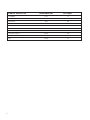
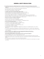
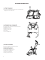
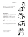
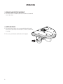
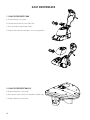
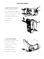
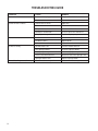
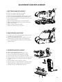
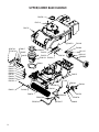
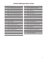
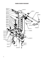
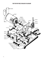
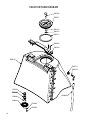
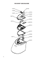
Dirt Dragon
WOOD FLOOR CLEANING MACHINE
Operator and Parts Manual
1001 Brown Avenue • Toledo, Ohio 43607-0127 • Customer Service: 800-441-1934
Fax: 800-942-2007 • Technical Service: 877-856-5954 • www.basicoatings.com
1
TABLE OF CONTENTS
Receiving the Machine.................................................... 3
Introduction.................................................................... 3
Technical Specifications................................................. 4
General Safety Regulations............................................ 5
Machine Preparation...................................................... 6
Operation................................................................... 7 - 8
Turning Off the Machine................................................. 9
Daily Maintenance................................................. 10 - 11
Troubleshooting........................................................... 12
Adjustments and Replacement.................................... 13
Parts Diagrams..................................................... 14 - 29
Electrical Wiring Diagram............................................ 30
Tool Kits........................................................................ 31
Tool Kit Diagrams.................................................. 32 - 33
Warranty....................................................................... 36
2
RECEIVING THE MACHINE
Immediately check, when receiving the machine, that all the materials indicated on delivery documents have been received
and also that the machine has not been damaged in transit. If it has been damaged, this damage must be immediately reported to the shipper and also to our customer service department. Only acting promptly in this manner will make it possible
to receive missing material and to be compensated for damage.
INTRODUCTION
This is an automatic scrubber which, via the mechanical action of the rotating brush and chemical action of a water/detergent
solution, can clean many types of wood flooring. As it advances, it also collects the dirt removed and the detergent solution
leaving the floor dry.
The machine must be used only for this purpose. Even the best machines will only work well if used correctly and kept in
good working order. We therefore suggest you read this instruction booklet carefully and re-read it whenever difficulties arise
while using the machine. Please contact our technical service department if you have any questions about the machine.
3
TECHNICAL DESCRIPTION Measurement Unit
Dirt Dragon™
Cleaning Width
Inches
15
Brush Diameter
Inches
3.5
Brush Rotation
RPM
800
HP
0.5
Vacuum Motor Power
WATT
800
Vacuum Motor Suction
Inches of Water
77
Solution Tank Capacity
Gallons
3.00
Recovery Tank Capacity
Gallons
3.25
Work Capacity
Ft²/Hr
14,530
Weight
Pounds
84
Brush Motor Power
4
GENERAL SAFETY REGULATIONS
The regulations below must be carefully followed in order to avoid harm to the operator and damage to the machine.
• Read all labels on the machine carefully. Do not cover them for any reason and replace them immediately if they become
damaged.
• The machine must be used exclusively by authorized and trained personnel.
• When operating the machine be careful of other people.
• The machine is not designed for cleaning carpets.
• The power cable outlet must be provided with a proper ground.
• Avoid damaging the power cable by crushing, bending, cutting or stressing it.
• Whenever the power cable is damaged, immediately contact a Basic service center.
• Do not mix different types of detergent as this may produce harmful gases.
• Machine storage temperature is between -10°F and 130°F, never store outside under humid conditions.
• Operating conditions: room temperature between 33°F and 100°F with relative humidity between 30% to 95%.
• Only use the machine in closed areas and do not expose it directly to rain.
• Never use the machine in an explosive environment.
• Do not use the machine as a means of transport.
• Never use acidic chemicals which could damage the machine.
• Avoid running the brushes with the machine stopped; this could damage the floor.
• Never vacuum up flammable liquids.
• Do not leave the machine unattended when it is plugged in.
• Do not allow the solution pump to run dry for more than 3 minutes.
• Never use the machine to gather dangerous powders.
• Use a powder fire extinguisher in case of fire. Do not use water.
• Do not hit against shelving or scaffolding.
• The operator must always be equipped with the appropriate personal protective equipment (gloves, shoes, helmet,
glasses, etc.)
• The machine is designed to wash and dry floors simultaneously. Signal the presence of wet floors with suitable signs.
• If the machine does not work properly, perform routine maintenance. Otherwise, request the assistance of our technical
service department.
• When replacing parts ask for ORIGINAL spare parts from your Authorized Dealer and/or Retailer.
• Always turn off the machine and disconnect the power supply whenever maintenance is performed.
• Never remove guards that require tools for removal.
• Never wash the machine with direct or pressurized jets of water or with corrosive substances.
• Have your equipment service center check the machine once a year.
• To prevent the formation of scale in the solution tank, do not store the machine with detergent solution in the tanks.
• Before using the machine make sure that all doors and covers are positioned as shown in this operating and maintenance
manual.
• When your machine is ready to be retired, it must be disposed of properly.
• Use only brushes furnished with the machine or those specified in the user's manual. Use of other brushes can compromise safety.
5
MACHINE PREPARATION
1. Lifting the machine
A. The machine should be lifted using the front of the handle and the
handgrip on the rear handle tower.
A
A
A
B
2. Instrument Panel Components
C
The instrument panel components are identified as follows:
A. ON/OFF Brush Control
B. ON/OFF Solution Control
C. ON/OFF Vacuum Control
D. Fuse Holder
E. Electrical Supply Cord
D
E
3. Machine Components
The machine components are identified as follows:
A. Auxiliary Solution Connection
B. Solution Flow Control Valve
C. Head Pressure Adjustment Bolt
D. Transport Wheel Engagement Lever
E. Handle Position Locking Device
F. Solution Level Sight Gauge
G. Auxiliary Vacuum Connection
G
E
F
A
B
C
D
6
OPERATION
1. Handle Adjustment
A. Open the cam handle to release the handle locking gears.
B. Move the handle either up or down to a comfortable operating
height or the storage position.
C. Close the cam handle to lock the gears back into place.
2. Machine Operation
A. Fill the solution tank with clean water at a temperature not exceeding 120°F. An operator can check the level of solution in the tank by
looking at the sight gauge on the side of the tank.
B. Add liquid detergent into the tank using the correct concentration
and manner specified by the manufacturer. Excess foam could
damage the vacuum motor, so be sure to use only the correct
amount of detergent.
C.
A
Always use low foam detergent and defoaming liquid.
Defoaming liquid should only be used in the recovery tank, never the solution tank.
D. Release the transport wheels by pressing on the foot lever. This will
lower the brush and squeegees onto the floor.
D
H
G
F
E. Plug the cord into a standard 120v outlet.
F. Turn on the Vacuum Switch
G. Turn on the Water Control Switch
H. Turn on the Brush Control Switch
E
7
OPERATION
3. Forward and Reverse Movement
A. The machine will scrub and vacuum water in both the forward and
reverse directions.
4. Overflow Device
A. The machine has a float in the recovery tank lid that will stop airflow to the vacuum motor when the water level in the solution tank
is too high.
B. The recovery tank must be drained when this happens.
8
SHUTTING DOWN THE MACHINE
1. End of Work
When shutting down the machine and before performing any type of maintenance:
A. Turn off the solution control valve.
B. Turn off the solution control switch, brush drive switch, and vacuum motor
switch.
C. Raise the brush deck off the floor using the foot lever.
D. Unplug machine from power source.
E. Remove both tanks from the machine and dump out residual solution.
F.
ALWAYS WEAR GLOVES.
9
DAILY MAINTENANCE
1. Clean the recovery tank
A. Remove lid from recovery tank.
A
B. Lift tank from machine in a vertical direction.
C. Rinse the inside of tank with warm water.
D. Replace tank on machine and replace clear recovery tank lid.
B
2. Clean the recover tank lid
A. Remove lid from the recovery tank.
B. Rinse all of the open cavities in the lid and the float ball cage.
C. Replace lid back on recovery tank.
10
DAILY MAINTENANCE
3. Clean the squeegee assemblies
A. Remove recovery tank from machine.
B
B
B. Release tabs holding squeegee assemblies in place.
C. Disconnect vacuum hose from squeegee assembly.
B
D. Clean squeegee assembly with water.
B
E. Connect vacuum hose to squeegee assembly.
F. Insert tabs back into place.
G. Replace recovery tank.
4. Clean the brush assembly
A. Remove finger nuts from right side of machine.
B. Remove right side retaining plate.
C. Pull brush out from the drive bearing.
D. Clean brush with water.
E. Insert brush into the drive bearing.
F. Replace right side retaining plate.
A
G. Tighten finger nuts on retaining plate.
11
TROUBLESHOOTING GUIDE
PROBLEM
CAUSE
REMEDY
The machine does not turn on
Power cord is unplugged
Plug Cord into 120V outlet
The fuse is blown
Replace fuse
Insufficient water on brush
Solution valve is closed
Open valve
No water in solution tank
Fill solution tank with water
Pump switch is off
Turn the solution switch on
Blockage in solution tube
Clean or replace the solution line
The pump is damaged
Repair or replace pump
The machine does not clean well
Brush drive switch is off
Turn on brush drive
The brush is worn
Replace brush
Drive belt is loose
Adjust belt tension
The floor is not dry
Vacuum switch is off
Turn the vacuum switch on
Dirty squeegee blades
Clean the squeegee blades
Dirty squeegee body
Clean the squeegee body
Vac hose not attached to shoe
Attach vac hose to the squeegee shoe
Squeegee blade is worn
Replace squeegee blade
Too much foam is generated
No defoamer in recovery tank
Add defoamer to recovery tank
12
ADJUSTMENTS AND REPLACEMENT
1. Belt Tension and Replacement
A. Remove the solution tank and recovery tank.
B. Remove the solution control valve handle.
C. Remove all of the bolts holding the main shroud to the base.
D. Loosen the jam nut holding the belt tension bolt in place.
E. Turn the belt tension bolt in the desired direction to increase
or decrease belt tension.
F. Tighten the jam nut back in place on the tension plate.
G. Replace the main shroud back on the machine base and
tighten all of the bolts.
H. Replace solution control valve handle.
I. Replace the solution and recovery tanks.
2. Head pressure adjustment
A. To increase or decrease the brush pressure, loosen the jam
nut holding the head regulator bolt.
B. Turn the head regulator bolt counterclockwise to increase
head pressure or clockwise to decrease head pressure.
C. Once in the desired position, tighten the jam nut to hold the
regulator in place.
3. Squeegee Blade Replacement
A. Remove recovery tank from machine
B. Release tabs holding squeegee assemblies in place
C. Disconnect vacuum hose from squeegee assembly
D. Loosen the finger nuts from the squeegee assembly
E. Remove squeegee retainer from inside of the squeegee mount
F. The squeegee blades are easily removed from the squeegee
retainer.
G. Install new blades onto the squeegee retainer.
H. Insert the squeegee retainer back into the squeegee mount
I. Tighten finger nuts to hold the squeegee retainer in place.
J. Reinstall squeegee assembly into the machine.
B
B
13
UPPER/LOWER BASE DIAGRAM
E88703
E88719
E88715
E83143
E88679
E88744
E88743
E88617
E83269
E88592
E88745
E88742
E88687
E88625
E81125
E83145
E88630
E88746
EP50154 E88743
E88691
E88626
E88627
E88628
E88888
E82761
E88629
E88690
E83550
E88597
E11973
E88588
E88588
EP50155
E88621
E88595
E81068
E88624
EP50159
EP50158
14
EP50156
EP50157
E85553
E88670
E88669
UPPER/LOWER BASE PARTS LISTING
Item# Part # Description
Qty.
Item# Part # Description
Qty.
2
E11973 Hose Clamp, 1/2" OD Hose, Snap Grip, Plastic
3
25
E88625 Right Side Brush Cover Weldment
1
4
EP50154 Vacuum Motor 120 VAC 800 Watt
1
26
E88626 Bearing, Ball, M19 OD x M10 ID x M5 T, Sealed 2
5
EP50155 Tubing, 1/4" ID x 7/16" OD x 140mm L, Braid Reinforced , PVC 1
27
E88627 Idler End Hub
1
6
EP50156 Tubing, 1/4" ID x 7/16" OD x 216mm L, Braid Reinforced , PVC 1
28
E88628 Snap Ring, External, M10, Zinc
1
7
EP50157 Tubing, 1/4" ID x 7/16" OD 228mm L, Braid Reinforced , PVC 1
29
E88629 Wheel - Front Roller
3
8
EP50158 Tubing, 1/4" ID x 7/16" OD 312 mm L, Braid Reinforced , PVC 1
30
E88630 Axle, Transport Wheels
1
9
EP50159 Tubing, 1/4" ID x 7/16" OD 133mm L, Braid Reinforced , PVC 1
31
E88669 Fitting, 1/8" MNPT x 1/4" Barb, Hose Barb, Brass 1
10
E81068 Washer, Fender, 1/4", Zinc
2
32
E88670 Fitting, Tee, Brass 1/8" MNPT x 1/8" FNPT x 1/8" FNPT 1
11
E81125 Wheel, 4" OD, 1/2" ID, Non Marking
2
33
E88679 Upper Frame
1
12
E82761 Washer, Flat, M6 x 12 x 1.6, Zinc
9
34
E88687 Set Screw, M6 x 20, SS
2
13
E83143 Axle Cap 0.5"
2
35
E88690 Bushing - Bumper Wheel
3
14
E83145 Nylon Washer
2
36
E88691 Gasket, Vacuum to Frame
1
15
E83269 Washer, Spring, 1/2" ID
2
37
E88703 Gasket, Vacuum-Tank Seal
2
16
E83550 Nut, Hex, M6, Nylon Lock, Zinc
3
38
E88715 Screw, 1/4" x 3/4", Plastite Pan Head, Zinc
15
17
E85553 Pump
1
39
E88719 Washer, Flat, M6 x M22 x M2, Zinc
4
18
E88588 Fitting, Elbow, 1/8" MNPT x 1/4" Barb, Brass
2
40
E88742 Splash Guard
2
19
E88592 Gasket, Upper Vacuum
1
41
E88743 Band Clamp
2
20
E88595 1/4" Inline Filter 130 micron
1
42
E88744 Screw, M3 x 6, Button Head, Socket, SS
3
21
E88597 Lower Base
1
43
E88745 Nut Plate
1
22
E88617 Thumb Nut
2
44
E88746 Screw, Machine, M3 x 12, Button Head, Socket, SS 3
23
E88621 Watering Tube
1
45
E88888 Bolt, Hex, M6 x 40, Zinc
24
E88624 Wood Floor Brush
1
3
15
HANDLE BASE DIAGRAM
E83381
E88601
E88600
E88593
E88708
E88599
E88701
E88602
E88801
E88606
E83881
E83879
E88605
E88812
E88813
E88598
E88607
E88751
E83550
E88594
E88632
E82761
E81180
E88596
E83836
E83879
E20123
E82256
E88696
E88622
E83879
E88889
E81076
E88594
E88673
E88672
E82256
E88715
16
E88747
E88603
HANDLE BASE PARTS LISTING
Item# Part # Description
Qty.
Item# Part # Description
Qty.
1
E20123 Washer, Split Lock, M5, Zinc
6
19
E88603 Pin, Clevis 3/16 x 0.75, Zinc
1
2
E81076 Nut, 3/8"-16, Nylon Lock, Grade 5, Zinc
2
20
E88605 Male Coupling
1
3
E81180 Serial Number Decal
1
21
E88606 O-Ring, M16 x 2.00
2
4
E82256 Nut, M5 x 7, Nylon Lock, Zinc
6
22
E88607 Handle Mounting Plate Weldment
1
5
E82761 Washer, Flat, M6 x 12 x 1.6, Zinc
8
23
E88622 Handle Nut Plate
1
6
E83381 Nut, M10, Nylon Lock, Zinc
1
24
E88632 Handle Adustment Cam Lock
1
7
E83550 Nut, Hex, M6, Nylon Lock, Zinc
8
25
E88672 Caster 2" OD, 3/8" - 16", 1" L Post
2
8
E83836 Bolt, Hex,t M5 x 16, Zinc
2
26
E88673 Washer, Fender 3/8" x 1 1/4" Zinc
3
9
E83879 Washer, Flat M5 x 11 x 1, Zinc
7
27
E88696 Screw, #8-32 x 0.375 Thread Forming, Pan Head, Phillips, Zinc 1
10
E83881 Hex Bolt M5 x 20 Zinc
4
28
E88701 Bumper
1
11
E88593 Handle Tower Pivot Shaft Hub
1
29
E88708 Grommet, EPDM 60 Durometer
1
12
E88594 Washer, Split Lock, M6 Zinc
16
30
E88715 Screw, 1/4" x 3/4", Plastite Pan Head, Zinc
6
13
E88596 Handle Tower Weldment
1
31
E88747 Bolt, Hex, M6 x 80, Zinc
8
14
E88598 Handle Adjust Gear
1
32
E88751 Screw,1/4"-20 x 5" Flat Head, Zinc
6
15
E88599 Handle Tower Pivot Shaft
1
33
E88801 Cotter Pin, 1/16" Hairpin
1
16
E88600 Bushing, Flange, 20mm ID, 24mm OD, 28mm Flange, 20mm L, Bronze 1
34
E88812 Male Coupling Shim 1/16"
1
17
E88601 Washer, M10 x 30 x 2.5, Zinc
1
35
E88813 Male Coupling Shim 1/8"
1
18
E88602 Handle Pivot Rod
1
36
E88889 Relay 120 VAC 1.5 HP
1
17
MOTOR DRIVE/LINKAGE DIAGRAM
E88620
E88665
E88667
E88594
E88584
E88666
E88585
E20123
E88619
E88656
E88512
E86701
E88655
E88590
E83836
E88589
E88916
E11973
E82773
E88587
E88796
E88648
E88740
E88591
E88588
E88584
E88688
E88585
E88580
E88594
E88646
E88583
E88581
E88586
E88581
E88582
E88513
18
E88654
E88601
E88640
E88642
E88644
E88645
E88626
E88641
E88628
E88609
E88623
E88628
E88653
E88649
E88647
E88643
E88652
MOTOR DRIVE/LINKAGE PARTS LISTING
Item# Part # Description
Qty.
Item# Part # Description
Qty.
1
E11973 Hose Clamp, 1/2" OD Hose, Snap Grip, Plastic
3
26
E88626 Bearing, Ball M-19 OD x M10 ID x M5 Thk, Sealed 1
2
E20123 Washer, Split Lock, M5 Zinc
1
27
E88628 Snap Ring, External, M10, Zinc
6
3
E82773 Washer, Flat, M10 x 21 x 2, Zinc
3
28
E88640 Tensioner Linkage Weldment
1
4
E83836 Hex Bolt M5x16 Zinc
1
29
E88641 Pulley Idler 27mm
1
5
E86701 Nut, Hex, M6, Zinc
1
30
E88642 Snap Ring, Internal, M19, Zinc
1
6
E88512 Drive Motor Support Weldment
1
31
E88643 Bushing, Flange 10 ID x 15 OD x 10 L, Bronze
3
7
E88513 Pulley Brush Drive 42.5mm
1
32
E88644 Hex Jam Nut M12x7 Zinc
1
8
E88580 Brush Drive Hub
1
33
E88645 Spring, Belt Tensioner
1
9
E88581 Bearing, Ball, M15 ID x M24 OD x M5 T
2
34
E88646 Tensioner Bolt
1
10
E88582 Snap Ring, Internal, M24 x 1.2, Zinc
1
35
E88647 Foot Pedal Weldment
1
11
E88583 Snap Ring, External, M15, Zinc
1
36
E88648 Bushing, Flange 15 ID x 19 OD x 16 L
1
12
E83836 Bolt, Hex, M6 x 18, Full Thread, Zinc
6
37
E88649 Screw, Set, M6 x 6 Cup Point, Zinc
6
13
E88585 Washer, Flat, M6 x18, Zinc
2
38
E88652 Foot Pedal Latch Weldment
1
14
E88586 Bearing Spacer
1
39
E88653 Pivot Linkage Lever Weldment
1
15
E88587 Quick Disconnect Male
1
40
E88654 Foot Pedal Link Weldment
1
16
E88588 Fitting, Elbow, 1/8" MNPT x 1/4" Barb, Brass
1
41
E88655 Foot Pedal Bracket Weldment
1
17
E88589 1/4" Needle Valve
1
42
E88656 Bolt, Hex, M6 x 90 Full Thread, Zinc, Grade 5
1
18
E88590 Fitting, Elbow, 1/4" MNPT x 1/4" Barb, Brass
1
43
E88665 Brush Drive Motor
1
19
E88591 Fitting, Straight, Brass 1/4" MNPT x 1/4" Barb
1
44
E88666 Pulley Drive Motor 25mm
1
20
E88594 Washer, Split Lock, M6 Zinc
13
45
E88667 Key, M4 x M4 x M16, Steel
1
21
E88601 Washer, M10 x 30 x 2.5, Zinc
2
46
E88688 Bolt, M6 x 12, Hex Head, Zinc
8
22
E88609 Drive Belt
1
47
E88740 Knob, Valve
1
23
E88619 Capacitor, Run
1
48
E88916 Screw, M3 x 8, Button Head, Socket, SS
2
24
E88620 Capacitor, Start
1
49
E88796 Screw, Set, M5 x 8 Cup Point, Zinc
1
25
E88623 Torsion Spring, Foot Pedal Lock
1
19
BUSHING PLATE DIAGRAM
E88649
E88663
E88664
E88648
E88601
E82773
E88654
E88688
E88594
E88643 E88628
E88662
E88650
E88659
E88657
E88661
E88651
E88626
E88658
20
BUSHING PLATE PARTS LISTING
Item# Part # Description
Qty.
Item# Part # Description
Qty.
1 E82773 Washer, Flat, M10 x 21 x 2, Zinc
2
12
E88654 Foot Pedal Link Weldment
1
2 E88594 Washer, Split Lock, M6 Zinc
8
13
E88657 Axle, Front Wheels
1
3 E88601 Washer, M10 x 30 x 2.5, Zinc
1
14
E88658 Front Wheel
2
4 E88626 Bearing, Ball M-19 OD x M10 ID x M5 Thk, Sealed 4
15
E88659 Spacer, Right Wheel
1
5 E88628 Snap Ring, External, M10, Zinc
3
16
E88661 Spacer, Inner Wheel
1
6 E88643 Bushing, Flange 10 ID x 15 OD x 10 L, Bronze
1
17
E88662 Pivot Linkage Lever Right Weldment
1
7 E88648 Bushing, Flange 15 ID x 19 OD x 16 L
1
18
E88663 Right Lift Arm Weldment
1
8 E88649 Screw, Set, M6 x 6 Cup Point, Zinc
6
19
E88664 Lower Frame Bushing Plate Weldment
1
10
E88650 Foot Pedal Axle
1
20
E88688 Bolt, M6 x 12, Hex Head, Zinc
8
11
E88651 Stiffing Rod
1
21
HANDLE DIAGRAM
E88638
E88636
E88692
E88637
E88639
E88694
E88698
E88705
E88757
E88706
E88708
E88773
E88601
E88758
E88598
E88750
E88811
E88696
E88695
22
E88600
HANDLE PARTS LISTING
Item# Part # Description
Qty.
Item# Part # Description
Qty.
1
E88598 Handle Adjust Gear
1
11
E88696 Screw, #8-32 x 0.375 Thread Forming, Pan Head, Phillips, Zinc 2
2
E88600 Bushing, Flange, 20mm ID, 24mm OD, 28mm Flange, 20mm L, Bronze 1
12
E88698 FUSE 120VAC, 20A
3
E88601 Washer, M10 x 30 x 2.5, Zinc
1
13
E88705 Screw, #8-18 x 0.50 Plastite, Pan Head, Phillips, Zinc 3
4
E88636 Switch, Clear Illuminated Rocker
1
14
E88706 Wire Clamp, Plastic, 1/2" ID
3
5
E88637 Switch, Red Illuminated Rocker
1
15
E88708 Grommet, EPDM 60 Durometer
2
6
E88638 Switch, Green Illuminated Rocker
1
16
E88750 Screw, 0.25-20 x 0.75 Flat Socket Head, Zinc
6
7
E88639 Cord, Pigtail
1
17
E88757 Handle Cover - Rear
1
8
E88692 Decal Handle
1
18
E88758 Handle Cover - Front
1
9
E88694 Fuse Holder, Panel Mount, 20A, 250VAC
1
19
E88773 Handle Weldment
1
10
E88695 Screw, #8-18 x 1.00 Plastite, Pan Head, Phillips, Zinc 16
20
E88811 Decal, Front Handle Cover, Basic
1
1
23
SQUEEGEE/HOSE DIAGRAM
E88684
E88674
E88615
E88617
E88720
E88611
E88604
E88616
E88671
E88614
E88612
E88618
24
E88613
SQUEEGEE/HOSE PARTS LISTING
Item# Part # Description
Qty.
Item# Part # Description
Qty.
1
E88611 Squeegee Shoe Outter
2
8
E88618 Bolt, Carriage, M6 x 40, SS
4
2
E88612 Squeegee Shoe Insert
2
9
E88671 Pin, Clevis, .1875 X 1.25, SS
8
3
E88613 Squeegee Blade Outter
2
10
E88604 Pin,Cotter M2 x 10, Zinc
8
4
E88614 Squeegee Blade Inner
2
11
E88720 O-Ring, Squeegee Shoe Hose Adaptor
2
5
E88615 Squeegee Shoe Hose Adaptor
2
12
E88674 Spring, Squeegee
4
6
E88616 Squeegee Wheel
8
13
E88684 Sqeegee Hose
1
7
E88617 Thumb Nut
4
25
SOLUTION TANK DIAGRAM
E88709
E88677
E88710
E88712
E88711
E88802
E88704
E88675
E88717
E88739
E88700
E88699
E88689
E88606
E88610
E20292
E88705
26
SOLUTION TANK PARTS LISTING
Item# Part # Description
Qty.
Item# Part # Description
Qty.
1
E20292 Washer, Flat, M4 x 9 x 0.8, Zinc
6
10
E88705 Screw, #8-18 x 0.50 Plastite, Pan Head, Phillips, Zinc 6
2
E88606 O-Ring, M16 x 2.00
2
11
E88709 Vent Pin, Cap
1
3
E88610 Female Coupling
1
12
E88710 O-ring, 7.0mm ID x 2.0mm W
1
4
E88675 Tank - Solution
1
13
E88711 Gasket, CAP
1
5
E88677 Solution Tank Cap
1
14
E88712 E Clip, 8M x 16 x 1, SS
1
6
E88689 Tubing, 8mm ID x 12mm OD x 208mm L, Clear 1
15
E88717 Grommet, M13 x M8
2
7
E88699 Plunger
1
16
E88739 Fitting, 8mm x 8mm Barbed, Elbow, Plastic
2
8
E88700 Plunger Spring
1
17
E88802 Screw, #10 x 1.25 Plastite, Flat Head, Zinc
4
9
E88704 Handle - Solution Tank
1
27
RECOVERY TANK DIAGRAM
E88716
E88748
E83879
E88707
E88678
E88749
E88685
E88631
E88798
E88718
E88799
E88714
E88797
E88890
E88713
E88800
E88676
28
RECOVERY TANK PARTS LISTING
Item# Part # Description
Qty.
Item# Part # Description
Qty.
1
E83879 Washer, Flat M5 x 11 x 1, Zinc
2
10
E88718 Float Ball 37mm
1
2
E88631 Gasket - Hinge Door
1
11
E88748 Hinge Spring
1
3
E88676 Tank - Recovery
1
12
E88749 DD2 Hinge Pin
1
4
E88678 Recovery Tank Upper Window Cover
1
13
E88797 Gasket, Lid to Tank, 1/4" Foam
1
5
E88685 Hinge Door
1
14
E88798 Gasket, Lid, Upper to Lower, Vacuum 18/8" Neoprene 1
6
E88707 Hinge Mount Plate
1
15
E88799 Gasket, Lid, Upper to Lower Solution, 1/8" Neoprene 1
7
E88713 Recovery Tank Seal
2
16
E88800 Hose Cuff, Elbow, Recovery Tank Lid Inlet
1
8
E88714 Recovery Tank Window Lower 1
17
E88890 Cable Tie 8x0.14 Plastic
1
9
E88716 Screw, #10 x 3/8", Thread Forming Plastic, Pan Head, Zinc 13
29
ELECTRICAL WIRING DIAGRAM
Pigtail With Twist Lock and
Strain Relief
120V
WHITE
GREEN
VACUUM SWITCH
WHITE
BLACK
YELLOW
WHITE
20 AMP
BLACK
VAC RELAY
BRUSH SWITCH
M
VACUUM
WHITE
RUN
BLACK
BLUE
M
START
BRUSH
GREEN
PUMP SWITCH
WHITE
BLACK
RED
PUMP
ELECTRICAL WIRING PARTS LISTING
Item# Part # Description
Qty.
Item# Part # Description
Qty.
1
E85553 Pump, Oscillating
1
8
E88698 Fuse, 120 VAC, 20 A 1
2
E88889 Relay, 120 VAC 1.5 HP
1
9
E88636 Switch, Clear Illuminated Rocker
1
3
E88665 Motor, Brush Drive
1
10
E88637 Switch, Red Illuminated Rocker
1
4
E88619 Capacitor, Run, 25 microfarad, 300 VAC, CBB60 1
11
E88638 Switch, Green Illuminated Rocker
1
5
E88620 Capacitor, Start, 150 microfarad, 250 VAC, CD60 1
12
E88683 Cord, Extension, SJTW, 12 ga, 20 A, 50' L, 3 Wire 1
6
E88639 Cord, Pigtail, Twist Lock ASM w/ Strain Relief
1
13
E50154 Vacuum Motor ASM 120 VAC 800 Watt
7
E88694 Fuse Holder, Panel Mount, 20 A, 250 VAC
1
30
1
TOOL KITS
The following predefined tool kits are available for purchase:
Hard Surface Tool Kit - EP50167
Includes:
EP50166 - Vacuum and Solution Hose Assembly
E88974 - 2-Piece Spray Wand Assembly
EP50172 - Flip Tool Assembly
E89542 - Mesh Tool Bag
Carpet & Upholstery Tool Kit - EP50168
Includes:
EP50166 - Vacuum and Solution Hose Assembly
E88974 - 2-Piece Spray Wand Assembly
E88964 - Carpet Head Assembly
E85515 - Upholstery Tool Assembly
E89542 - Mesh Tool Bag
EP50166 - Vacuum and Solution Hose Assembly
Complete Tool Kit - EP50170
Includes:
EP50166 - Vacuum and Solution Hose Assembly
E88974 - 2-Piece Spray Wand Assembly
EP50172 - Flip Tool Assembly
E88964 - Carpet Head Assembly
E85515 - Upholstery Tool Assembly
E88976 - Spray Wand Assembly
E89542 - Mesh Tool Bag
E88974 - 2-Piece Spray Wand Assembly
EP50172 - Flip Tool Assembly
E85515 - Upholstery Tool Assembly
E88976 - Spray Wand Assembly
E88964 - Carpet Head Assembly
31
TOOL KIT DIAGRAM
Hose Assembly and 2 Piece Wand
E88890
E88962
E88977
HOSE, VACUUM
SPRAY ASSEMBLY
EP50166
E88968
E88752
E88965
E88975
2 PIECE SPRAY
WAND ASSEMBLY
E88974
E88633
E88959
TOOL KIT PARTS LISTING
Part #
Description
Part #
Description
E88633
Solution Hose
E88968
Solution Tube and Fitment
E88752
Clamp, Solution Valve
E88974
Wand, Vacuum, 2 Piece Assembly
E88890
Cable Tie, 8" x 1/8", Plastic
E88975
2-Piece Wand Tube
E88959
Spray Jet
E88977
Solution Hose, PVC Clear Braided
E88962
Hose, Vac, 1.5" Dia x 10Ft L, Asm w/ Cuffs
EP50166
Solution & Vac Hose Assembly
E88965
Trigger Valve
32
TOOL KIT DIAGRAM
Tool Head
E88970
E88978
E88963
E88960
CARPET HEAD
ASSEMBLY
E88964
E88965
E88959
SPRAY WAND
ASSEMBLY
E88976
FLIP TOOL
ASSEMBLY
EP50172
E88963
E88970
E88971
E88961
E88969
FLIP TOOL
BRUSH ASSEMBLY
EP50171
E88972
E89551
E88973
TOOL KIT PARTS LISTING
Part #
Description
Part #
Description
E85515
Upholstery Tool
E88971
Screw, Squeegee Mount
E88959
Spray Jet
E88972
Screw, Brush Mount
E88960
Extension, Spray Wand
E88973
Squeegee Blade
E88961
Brush, Flip Tool
E88976
Spray Wand Assembly
E88963
Retaining Ring
E88978
Solution Hose, Spray Wand
E88964
Carpet Head Assembly
E89551
Screw, Brush Mount Bar"
E88965
Trigger Valve
EP50171
Brush Assembly, Complete
E88969
Mounting Bar, Brush
EP50172
Complete Flip Tool Assembly With Brush
E88970
O-Ring
33
34
35
BASIC® COATINGS U.S. WARRANTY POLICY
10 year coverage
3 Year Coverage
1 Year Coverage
Subject to the conditions stated below,
Basic Coatings warrants parts and labor
on rotationally molded polyethylene
tanks/housings and injection molded
vacuum head assemblies to be free
from defects in materials and workmanship for a period of ten years to the
original purchaser.
Subject to the conditions stated below,
Basic Coatings warrants parts and labor
on all other Basic Coatings components
to be free from defects in materials and
workmanship for a period of three years
to the original purchaser.
Subject to the conditions stated below,
Basic Coatings offers a limited warranty
on parts and labor on the following
equipment: parts and accessories to
be free from defects in materials and
workmanship for a period of one year to
the original purchaser.
• All Tools and Accessories
• Dust Dragon Bac Pac Vac #EB85808-12
*Wear Items exempt from Warranty consideration include but may not be limited to: power cords, transport wheels,
vacuum bags, belts, squeegee blades, pad drivers, clutch plates, handle grips, filters, screens, throttle cables, brushes
and carbon brushes.
Subject to the conditions and exceptions stated in this warranty, Basic Coatings warrants the Basic Coatings products to be
free from defects in material and workmanship, under normal use and service, for the periods listed under the warranty policy
to the original purchaser. At any time during the warranty period, Basic Coatings will furnish replacement parts for the Basic
Coatings parts to the original purchaser. Such parts will be furnished and charged including transportation costs, to the original owner through any Basic Coatings authorized Service Distributor. If the original part is returned within the warranty policy
period from date of delivery for inspection by Basic Coatings and is found to be defective the owner will be credited for the
cost of replacement parts plus shipping and handling. Replacement parts that have become defective through wear or abuse
are not included in this warranty.
This warranty does not apply to damage or defect caused by accident, misuse, negligence, fire, or to any Basic Coatings
product which has been serviced or repaired by other than an authorized Basic Coatings Service Distributor or Basic Coatings
factory personnel. This warranty is void if products are used for any purpose other than that which was intended. There are
no other warranties expressed or implied. In no event shall Basic Coatings be liable for incidental or consequential damages
or any damage to person or property. (Please note some states do not allow the exclusion or limitations for incidental and
consequential damages).
©2012 Basic Coatings
All Rights Reserved.
1001 Brown Avenue
P.O. Box 3126
Toledo, Ohio 43607
800-441-1934
www.basiccoatings.com
36
Item #EB85-9212 | 03/12 D