1
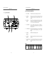
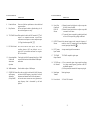
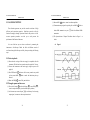
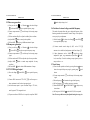
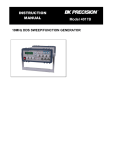
FUNCTION GENERATOR
USER MANUAL
EC Declaration of Conformity
We
GOOD WILL INSTRUMENT CO., LTD.
(1) No. 95-11, Pao-Chung Rd., Hsin-Tien City, Taipei Hsien, Taiwan
(2) Plot 522, Lorong Perusahaan Baru 3, Prai Industrial Estate, 13600 Prai, Penang, Malaysia
declares that the below mentioned product
GFG-8210
is herewith confirmed to comply with the requirements set out in the Council Directive
on the Approximation of the Law of Member States relating to Electromagnetic
Compatibility (89/366/EEC, 92/31/EEC, 93/68/EEC) and Low Voltage Equipment
Directive (73/23/EEC).
For the evaluation regarding the Electromagnetic Compatibility and Low Voltage
Equipment Directive, the following standards were applied:
EMC Directive 89/366/EEC amended by 92/31/EEC; 93/68/EEC
EN 50081-2 (1992):
Electromagnetic Compatibility- Generic
Emission Standard.
Part 2: Industrial environment.
Conducted and Radiated Emissions
EN 55011:1998 Group 1 Class A
Current Harmonic
EN 61000-3-2 (1995)
Voltage Fluctuation
EN 61000-3-3 (1995)
EN 50082-2 (1992):
Electromagnetic Compatibility- Generic
Immunity Standard.
Part 2: Industrial environment.
Electrostatic Discharge
EN 61000-4-2: 1995
Radiated Immunity
EN 61000-4-3: 1996
Electrical Fast Transients
EN 61000-4-4: 1995
Surge Immunity
EN 61000-4-5: 1995
Voltage Dips/ Interrupts
EN 61000-4-11: 1994
Low Voltage Equipment Directive 73/23/EEC & amended by 93/68/EEC
Safety Requirements
IEC 61010-1:1990+A1:1992+A2:1995; EN 61010-1: 1993+A2:1995;
2
FUNCTION GENERATOR
FUNCTION GENERATOR
USER MANUAL
TABLE OF CONTENTS
USER MANUAL
PAGE
1.SAFETY TERMS AND SYMBOLS
1.
SAFETY SUMMARY… … … … … … … … … … … … … … … … … ..
1
2.
INTRODUCTION… … … … … … … … … … … … … … … … … … …
5
3.
SPECIFICATION… … … … … … … … … … … … … … … … … … …
6
4.
FUNCTION DESCRIPTION.… … … … … … … … … … … … … … .
11
5.
USAGE DESCRIPTION… … … … … … … … … … … … … … … … .
14
6.
APPLICATION NOTE… … … … … … … … … … … … … … … … …
20
WARNING. Warning statements identify condition or
7.
MAINTENANCE… … … … … … … … … … … … … … … … … … … .
30
practices that could result in injury or loss of life.
Please take a moment to review these safety terms and symbols
which may appear in this manual or on Equipment to prevent
damage to the Function Generators.
CAUTION. Caution statements identify conditions or
practices that could result in damage to this product or
other property.
3
1
FUNCTION GENERATOR
FUNCTION GENERATOR
USER MANUAL
USER MANUAL
FOR UNITED KINGDOM ONLY
DANGER High Voltage
NOTE: This lead/appliance must only be wired by
competent persons
ATTENTION refer to Manual
WARNING: THIS APPLIANCE MUST BE EARTHED
IMPORTANT: The wires in this lead are coloured in
accordance with the following code:
Protective Conductor Terminal
Green/ Yellow: Earth
Blue:
Neutral
Brown:
Live(Phase)
(ground) Earth Terminal
Frame or Chassis Terminal
As the colours of the wires in main leads may not
correspond with the colours marking identified in your
plug/appliance, proceed as follows:
The wire which is coloured Green & Yellow must be
connected to the Earth terminal marked with the letter E or
by the earth symbol
or coloured Green or Green &
Yellow.
2
3
FUNCTION GENERATOR
FUNCTION GENERATOR
USER MANUAL
The wire which is coloured Blue must be connected to the
terminal which is marked with the letter N or coloured Blue
or Black.
USER MANUAL
2. INTRODUCTION
The GFG -8210 Function Generator is a stable low distortion
instrument which generate signals in the frequency range up to 10MHz.
Typical applications include a wide range of audio response testing
The wire which is coloured Brown must be connected to the
terminal marked with the letter L or P or coloured Brown or
Red.
applications, vibration testing, servo system evaluation, ultra sound
applications, and etc.
If in doubt, consult the instructions provided with the
equipment or contact the supplier.
This cable/appliance should be protected by a suitably rated
and approved HBC mains fuse : refer to the rating
information on the equipment and/or user instructions for
details. As a guide, cable
of 0.75mm² should be protected by a 3A or 5A fuse. Larger
conductors would normally require 13A types, depending on
the connection method used.
The instrument includes the following features: logarithmic and linear
Any moulded mains connector that requires removal
/replacement must be destroyed by removal of any fuse &
fuse carrier and disposed of immediately, as a plug with
bared wires is hazardous if a engaged in live socket. Any
re-wiring must be carried out in accordance with the
information detailed on this label.
sweep capabilities, together with a built in frequency counter.
The
sweep capability simplifies the task of finding resonant points of speakers,
filter networks and other networks/structures. An oscilloscope may be
connected to this instrument for the respons e to be displayed. The
counter can be switched to measure and display the frequency of an
external signal up to 150MHz.
l
ADDITIONAL FEATURES
1. Low distortion waveforms (sine, triangular and square).
2. Signal output in eight decade stages, 0.1Hz to 10MHz.
3. Adjustable sweep time and sweep width both in linear and logarithmic
modes.
4. Duty cycle control with signal inversion capability.
5. External Voltage controlled Frequency (VCF).
6. A second output for TTL or adjustable CMOS pulses.
7.50 ohm main signal output with DC offset adjustment and 20dB
attenuation capability.
8. Supplied with two BNC test leads and AC power cord set.
4
5
FUNCTION GENERATOR
FUNCTION GENERATOR
USER MANUAL
USER MANUAL
3. SPECIFICATION
GFC-8210
GFG-8210
1.Main
Frequency Range
Amplitude
Impedance
Attenuator
DC Offset
Duty Control
Display
0.1Hz∼ 10MHz (8 Range)
≧10Vpp (into 50Ωload)
50Ω ±
10%
-20dB±1dB×
2
<-5V∼>5V (into 50Ω load)
15%:85%:15% to 1MHz Continued variable(square wave only)
6 digits LED display
2.Sine Wave
8.Sweep Operation
Sweep/Manual
Switch selector
Sweep/Rate
Sweep/Time
Sweep/Mode
>100:1 ratio max. and adjustable
0.5Sec∼30Sec adjustable
Lin./Log. switch selector
Sweep Out
0V~10±1V
9. Frequency Counter
Int./Ext.
Switch selector
Range
0.1Hz∼ 10MHz (5Hz~150MHz EXT)
Distortion
1% typical , <3% max at 1kHz.
Accuracy
±0.45dB ( ±5%)
Time base accuracy ±1 count
Flatness
Time Base
±20ppm (23℃±
5℃) after 30 minutes warm up
The maximum resolution is 100nHz for 1Hz and 1Hz for
100MHz.
3.Triangle Wave
Linear
Resolution
≧98% to 100kHz
4.Square Wave
Symmetry
Rise time
Input Impedance
±2%, 1Hz∼100kHz
≦35ns
5.CMOS Output
Max. Frequency
Level
Rise or Fall Time
2MHz
≦4Vpp∼14.5Vpp±0.5Vpp adjustable
≦120ns
6.TTL Output
Level
Rise or Fall Time
≧3Vpp
≦20ns
7.VCF
Input voltage
Input Impedance
0V∼ 10V (100:1)
10kΩ±
10%
6
Sensitivity
1MΩ/150nF
≦35mVrms(5Hz~100MHz)
≦45mVrms(100MHz~150MHz)
10.General
Power Source
AC115V, 230V±
15% 50/60Hz
Indoor use, altitude up to 2000m.
Ambient Temperature 0℃ to 40℃.
Operation
Relative Humidity 80% (Maximum).
Environment
Installation category II
Pollution Degree
2
Storage temperature -10℃ to 70℃.
& Humidity
70% (Maximum).
GTL-101 × 2
Accessories
Instruction manual × 1
Dimension
251(W)×91(H)×291(D) m/m
Approx. 2.2 kg
Weigh
7
FUNCTION GENERATOR
FUNCTION GENERATOR
USER MANUAL
USER MANUAL
l
Fig 4.1 FRONT PANEL
WARNING? To avoid electrical shock, the power cord
6
4
2
12a
7
protective grounding conductor must be connected to
ground.
GATE
0.01
0.1
1
10
1M
CAUTION? To avoid damaging the instrument, do not use
OVER
M
k
FREQUENCY
m
Hz
10k
10M
1k
100
10
1
ATT
-20dB
GATE
SWEEP
DUTY
it in a place where ambient temperature exceeds 40℃.
100k
CMOS
OFFSET
AMPL
OUTPUT
OUTPUT
TTL/CMOS
50
POWER
0
SLOW
COARSE
MAX
FAST
TIME
FINE
PULL SWEEP ON
5V
ADJ
15V
-
CMOS ADJ
TTL
RATE
PULL LOG
+
MIN
ADJ
MAX
-20dB
R
GFG-8210
FUNCTION GENERATOR
CAUTION? To avoid damaging the instrument, do not
input more than DC15V to V.C.F.(V.C.G.).
3
1
13
5
14
9
10
11
CAUTION? To avoid damaging the instrument, do not
input more than AC150V to Frequency Counters
8
9
2a
12
17
8
19
FUNCTION GENERATOR
FUNCTION GENERATOR
USER MANUAL
USER MANUAL
4. FUNCTION DESCRIPTION
Fig.4-2 REAR PANEL
15
20
115
l
COUNTER
INT
1.
Power Switch
Connect the AC power, then press power switch.
2.
Gate Time
Indicator
Press the power switch, Gate time indicator will start
to flash (the gate time of internal counter is 0.01
second).
2a.
Gate Time
Selector
Press this key to change gate time when use external
counter mode. The change order is according to 0.01s,
0.1s, 1s,10s cycle by pressing these keys.
3.
Over Indicator
In the external counter mode, the indicator is
illuminated when the output frequency is greater than
the range selected.
4.
Counter Display
Shows the external frequency by 6×0.3" green display,
and shows the internal frequency by 5×0.3" green
display.
5.
Frequency
Indicator
Indicate the current frequency value.
6.
Gate Time
Indicator
Indicate the current Gate time (external. counter mode
use only).
7.
Frequency Range To select the required frequency range by pressing the
Selector
relevant push button on the panel as shown in
Table 1.
28VA 22W
EXT
AC
VCF
INPUT
SWEEP
OUTPUT
COUNTER
INPUT
DC 15V
MAX
18
WARNING
AC
30Vrms
MAX
CAT
TO AVOID SHOCK, REMOVE
INPUTS BEFORE OPENING.
FUSE
RATING
115V T0.25A 250V
230V T0.125A 250V
16
Table 1
Push bottom
Frequency
Range
10
1
10
100
1k
10k
100k
1M
1.3Hz 1Hz 10Hz 100Hz 1kHz 10kHz 100kHz
∣
∣
∣
∣
∣
∣
∣
1Hz 10Hz 100Hz 1kHz 10kHz 100kHz 1MHz
11
10M
1M
∣
10M
FUNCTION GENERATOR
FUNCTION GENERATOR
USER MANUAL
8.
Function Selector
9.
Duty Function
10.
TTL/CMOS Selector When push in the knob, the BNC terminal of
will
output a TTL compatible waveform. If pull out and
rotate the knob can adjust the CMOS compatible output
(5-15Vpp) from the output of BNC .
11.
12.
DC Offset Control
Output Amplitude
Control with
Attenuation
Operation
12a. 20dB Attenuation
13
Press one of the three push buttons to select the desired
output waveform.
Pull out and rotate the knob to adjust the duty cycle of
the waveform (Square wave only).
Pull out the knob to select any DC level of the
waveform between ±10V, turn clockwise to set a
positive DC level waveform and invert for a negative
DC level waveform.
Turn clockwise for MAX. output and invert for a –20dB
output. Pull the knob out for an additional 20dB output
attenuation.
USER MANUAL
14
Sweep Time
Control and
LIN/LOG
Selector
(3) To proceed Linear sweep mode by pushing in the knob,
or select LOG sweep mode by pulling out the knob.
15.
INT/EXT Counter Select internal counter mode (count the frequency of
Selector
model) or select EXT counter mode for an independent
counter (input signal from BNC 16 ).
16.
EXT. Counter
Input Terminal
Accepts external signals for measurement.
17.
TTL/CMOS
Output Terminal
TTL/CMOS compatible signal output
18.
VCF IN/Sweep
Out Terminal
(1).Use to connect the input voltage required to perform
the “voltage control frequency” operation or the EXT
modulation operation.
(2).In Sweep mode, this terminal will output sweep signal.
19.
Main Output
Terminal
Main signal output.
20.
Power Switch
115V and 230V selectable.
Press the knob to adjust a –20dB output.
SWEEP ON Selector Pres s and turn clockwise the knob for MAX frequency
and Frequency
and invert for MIN frequency. (outer knob is for coarse
Adjustment
adjustment, and internal knob is for fine adjustment.)
(Sweep On/Off)
Pull out the knob to start the auto sweep operation; the
upper frequency limit is determined by the knob
position.
12
(1) Rotate the outer knob clockwise to adjust sweep time
for MAX, or invert for MIN.
(2) Rotate the outer knob clockwise to adjust sweep width
can control 0 to 100 times.
13
FUNCTION GENERATOR
FUNCTION GENERATOR
USER MANUAL
USER MANUAL
5. USAGE DESCRIPTION
(3) Rotate AMPL
12
again to control waveform amplitude.
(4) If attenuation output signal is required, pull out AMPL
These function generator can provide versatile waveforms of high
efficiency and convenient operation. Familiarize yourselves with the
function thoroughly through Operation Manual and practice with all
accurate operation procedures can lead you to easily master the
performance of the Function Generator.
obtain 20dB attenuation or press
l
Figure 1.
instrument to Oscilloscope. Watch the effect in different control of
waveforms through Oscilloscope carefully when proceeding the following
steps:
5-1.First-step check:
(1) Ensure that the voltage of the main supply is compatible with this
instrument. The label on the rear panel states the required AC voltage.
(2) Connect the instrument to the main supply using the power cord
supplied.
(3) Press PWR switch 1 and ensure all the rotary controls are pushed
in, then rotate AMPL 12 knob to make the indication point up
forward.
(4) Rotate the FREQ
13
control fully anticlockwise.
5-2.Triangle, square and sine wave
(1) First select Function 8 , and select Range 7 , rotate FREQ
to set the required frequency.(read out from display window).
13
,
(2) At this moment, connect Output
, to oscilloscope for observing
output signal, or connect to other experiment circuit.
14
knob to
knob for additional 20dB
attenuation..
(5) The phase-relation of Output Waveform shown in Figure 1 as
below:
It is one of the best ways to observe waveforms by connecting the
12
15
FUNCTION GENERATOR
FUNCTION GENERATOR
USER MANUAL
USER MANUAL
10
5-3.Pulse wave generation
(1) First pres s the key (
) of Function
8
7
, and rotate FREQ 13 , to set required frequency range.
(2) Connect output-terminal
to oscilloscope for observing output
signal.
(3) Pull out and rotate Duty ‰ to adjust the width of pulse waveform.
(4) Adjust AMPL 1 2 knob to control pulse amplitude.
(5) Pull out AMPL 12 knob to get 20dB attenuation of output.
5-4.Ramp wave generation
(1) First press the key (
) of Function
8
knob to adjust voltage level.
; then select Range
, then select Range
7
5-6.Variation of external voltage -controlled frequency
This mode of operation allows the user to adjust the frequency of the
function generator with an external DC control Voltage. It also provides
an easy way for your adjustment.
(1) Select Function 8 first, then select Range
to set required frequency range.
7
, rotate FREQ
13
(2) Connect external control voltage (0 ±10V) to the VCF
, rotate FEEQ 1 3 switch to set required frequency range.
(2).Connect output-terminal
to oscilloscope for observing output
signal.
connector via a suitable lead, and generate signal from Output
.
12
(3) Other adjustments, such as AMPL
switch can change
amplitude of signal, or get attenuation; adjust Offset 11 for DC
(3) Pull out and rotate DUTY‰ to adjust the slope of ramp waveform.
level, rotate Duty ‰ switch can change output signal of pulse or
(4).Adjust AMPL
waveform.
12
(5).Pull out AMPL
12
knob to control output amplitude of ramp
ramp waveform etc..
5-7.Auto Sweep
knob to obtain 20dB attenuation of output.
5-5.TTL/CMOS signal output
(1) First select Range
range.
7
, rotate FREQ
13
to set required frequency
(1) First select the required waveform by pressing Function
then select required frequency range by pressing range
button.
(2) Connect output terminal
signal.
(2) Connect BNC connector of TTL/CMOS
to oscilloscope or to
other experiment circuit for observing output signal.
(3) At this moment, output is square waveform fixing to TTL level;
suits for general TTL integrated circuit.
(3) Rotate frequency
13
button,
8
7
push
to oscilloscope for observing output
to determine the upper limit frequency.
(4) Pull out frequency 13 to perform auto-sweep operation.
(5) Rotate SWEEP/TIME 14 and SWEEP/RATE 14 to adjust sweep
time and rate.
(6) Pull out (press) LIN/LOG
14
to obtain LOG (LIN) sweep mode.
(4) If square waveform of CMOS level is required, can pull out CMOS
Note: The sweep width can only be adjusted during the sweep cycle
16
17
FUNCTION GENERATOR
FUNCTION GENERATOR
USER MANUAL
USER MANUAL
and it can not be stopped.
l Figure 2.
5-8. Precaution item
(1) Adjust DC OFFSET, will provide to change voltage of ±
10V (no
load) or ±5V (50Ω load). However, signal added DC level, is
still limited to ±20V (no load) or ±10V (50Ω load). In case of
over-voltage, clip will appear as shown in Figure 2:
(2) Output connector label 50 Ω , indicated that signal source
impedance is 50Ω.
Connect to any of impedance circuit, but
output voltage and terminal impedance will be rated. To avoid
oscillation, terminal shall be connected to 50Ω (When using high
frequency and square output), and its connecting line shall be as
short as possible.
(3) When adjust Duty knob to leftward position, the ratio of positive
state to negative state, expand to not less than 80:20. It can expand
Square wave to Pulse wave, expand Triangle wave to Ramp wave
l Figure 3.
and Sine wave to unsymmetrical Sine wave. As shown in Figure
3 is for adjustment of Duty control to obtain required waveform.
18
19
FUNCTION GENERATOR
FUNCTION GENERATOR
USER MANUAL
USER MANUAL
6. APPLICATION NOTE
(D) Using the Square wave test the characteristics of amplifier circuit.
This section describes the application of the Funct ion Generators in
details as well as a brief description relating to the block diagram. Only
It can’t actually explain the transient response of amplifier by using
Sine wave for the frequency response curve observation, but using
for the essential application method.
the high order poly -wave, Square wave, instead to display its
waveform from the oscilloscope can show up many characteristics of
(A) Trouble-shooting using signal-tracing method.
This method is similar to signal replacing way. The signal of model
amplifier.
(a) Using the circuit of figure 5, the 50Ω connector trim the
will be fixedly sent to input terminal. Observing its signal wave on the
oscillation effect of Square wave.
oscilloscope from front stage to rear stage orderly until appear a
(b) Use the output of Triangle wave, adjust the amplitude until there
signal with normal input but with abnormal output.
are no clipping happened in the applied frequency.
(c) Select Square wave, adjust frequency, choose to watch the
(B) Use as bias source and signal source circuit.
Utilize the Figure 4 of connecting type, which can provide bias of a
transistor and signal input. The output waveform can be observed
from oscilloscope. Adjust to the best condition with output max.
wave-form of middle of amplifier pass band, like 20Hz, 1kHz,
10kHz and etc.
(d) The output waveform of (c), must get something with frequency
Figure 6 shows some possible conditions.
amplitude and no distortion. Adjust DC OFFSET to see the different
effect of different bias condition.
CAUTION: The composed poly-wave frequency of
(C) Amplifier over-load characteristics
The Sine wave input will be different from output the overload point.
Square wave is quite large, so it’s not suitable for the
narrow band amplifier testing.
Using Triangle wave will easily observe the display of oscilloscope.
It can decide the linear range of output waveform. And the largest
no-distortion output amplitude.
(E) Test of logic circuit
This equipment is suitable for logic circuit testing. Using Square or
Pulse wave can analyze or watch the frequency waveform of a
designed testing circuit.
Also the DC Offset effect, drive the
plug-in model board or logic circuit trouble-shooting and etc. Used
20
21
FUNCTION GENERATOR
FUNCTION GENERATOR
USER MANUAL
as signal tracing and signal replacing operation:
USER MANUAL
in low frequency. But in approaching the resonant frequency,
there are still increasing in voltage, then the impedance can be
(a) Connect the lines as Figure 7.
(b) According to the operation guide in this manual, set Square wave
tested as following:
or Pulse wave output.
(c) Use the label TTL, CMOS output terminal testing TTL logic
(1) Series connect a R1 to the network under test as in Figure 9.
(2) Get voltage read out in E1, E2, adjust R1 until E2 is equal to
circuit.
(d) To test CMOS circuit by pulling up the switch of TTL/CMOS,
one half of E1.
(3) Under this frequency, the impedance network is the same as
and adjust CMOS level by rotating the switch to set the proper
the R1.
level
(e) Use dual-trace scope to show the input -output timing relation
judged by the two waves shown in Figure 4.
(G)Act as automatic test of speaker
Because there provide the auto feature in this equipment, the output
can drive to amplifier for testing the frequency response of speaker.
(F)Testing of speaking and impedance network
(a)
Set Auto/Manual to Auto position.
This equipment can be used to test the frequency characteristics of
speaker or any impedance network. It also can get the resonant
(b)
(c)
Set function to Sine wave
Set Range to 20kHz
frequency of network.
(d)
Sweep mode (LIN, LOG), sweep width, sweep time can be
(a) Connect the device under test as in Figure 8, can use oscilloscope
in stead of voltmeter.
(b) When use voltmeter, adjust the frequency of instrument record
down voltage relative to frequency.
set in any value.
(e)
The line connected is showed in Figure 11.
(c) When testing speaker, if there is a peak volt value, when in low
freq., this must be the resonant freq. of this speaker, see Figure
10. Whether installation may cause any effect to this frequency
or not? The proper design of case-installation will cause two
small ramps on both sides of this sharp ramp.
(d) In testing other impedance network, the resonant may not occur
22
23
FUNCTION GENERATOR
FUNCTION GENERATOR
USER MANUAL
l
USER MANUAL
l
FIGURE 4
24
FIGURE 5
25
FUNCTION GENERATOR
FUNCTION GENERATOR
USER MANUAL
USER MANUAL
l FIGURE 7
l FIGURE 6
l FIGURE 8
26
27
FUNCTION GENERATOR
FUNCTION GENERATOR
USER MANUAL
l FIGURE 9
USER MANUAL
l FIGURE 11
l FIGURE 10
28
29
FUNCTION GENERATOR
FUNCTION GENERATOR
USER MANUAL
USER MANUAL
7. MAINTENANCE
7-2.Fuse Replacement Procedure
The following instructions are used by qualified person only. To avoid
electrical shock, do not perform any service other than contained in the
When you proceed calibration or maintenance of the Function
Generators, if you want to replace the fuse, the upper cover must be
operation instructions unless you are qualified to do so.
removed according to the following steps:
7-1.Fuse Rating and type
1).The handle must be turned downward 90 degrees first.
If the fuse blows, the FUNCTION GENERATOR will not operate.
Try to determine and correct the cause of the blown fuse, then replace the
fuse with the correct rating and type shown below:
MODEL
GFG8210
FUSE Rating and Type
115V
230V
T0.25A 250V T0.125A 250V
Rating Input
Watts
VA
22
28
WARNING: For continued fire protection, replace only
with a 250V fuse of the specified type and rating, and
disconnect the power cord before proceeding fuse
replacement.
30
31
FUNCTION GENERATOR
FUNCTION GENERATOR
USER MANUAL
USER MANUAL
2).Pull apart the handle from the Function Generator. Please turn the
4).Please use a screwdriver to open the screw located at upper side of rear
handle left and right side slightly, that will make easier to pull off the
handle.
panel. Therefore, the upper cover can pull toward the backside. In the
meantime, the upper cover is moved.
3).There are two washers inside of two holes (the joints of handle and
case) respectively.
Please use a screwdriver to pry open these
washers.
Note: If you want to install the upper cover, please reverse above
steps.
7-3. Cleaning
To keep the instrument clean, wipe the case with a damp cloth and
detergent. Do not use abrasives or solvents.
32
33