1
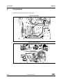
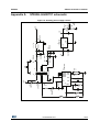
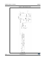
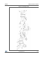
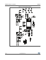
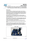
UM1694
User manual
STEVAL-ILH007V1: 150W HID digital ballast based on STLUX385A
Introduction
This document describes 150 W high intensity discharge (HID) digital ballasts driven by
STLUX385A devices. This platform is a solution to drive HID lamps (sodium and metal
halide). The board is composed of two stages:
1.
Power factor corrector (PFC), based on boost topology to correct the AC input current
in phase with AC voltage mains.
2.
Inverter, based on full bridge topology to drive the lamps.
The STLUX385A digital controller drives both stages.
Figure 1. STEVAL-ILH007V1
June 2015
DocID025509 Rev 1
1/30
www.st.com
30
Contents
UM1694
Contents
1
Features . . . . . . . . . . . . . . . . . . . . . . . . . . . . . . . . . . . . . . . . . . . . . . . . . . . 5
2
Connectors . . . . . . . . . . . . . . . . . . . . . . . . . . . . . . . . . . . . . . . . . . . . . . . . 6
3
Firmware . . . . . . . . . . . . . . . . . . . . . . . . . . . . . . . . . . . . . . . . . . . . . . . . . . 8
3.1
4
5
STEVAL-ILH007V1 firmware . . . . . . . . . . . . . . . . . . . . . . . . . . . . . . . . . . . 8
3.1.1
Implemented peripherals . . . . . . . . . . . . . . . . . . . . . . . . . . . . . . . . . . . . . 9
3.1.2
Used pins . . . . . . . . . . . . . . . . . . . . . . . . . . . . . . . . . . . . . . . . . . . . . . . 11
3.1.3
Module summary . . . . . . . . . . . . . . . . . . . . . . . . . . . . . . . . . . . . . . . . . . 14
Firmware download into the STLUX MCU . . . . . . . . . . . . . . . . . . . . . . . 15
4.1
Setup . . . . . . . . . . . . . . . . . . . . . . . . . . . . . . . . . . . . . . . . . . . . . . . . . . . . 15
4.2
Installation . . . . . . . . . . . . . . . . . . . . . . . . . . . . . . . . . . . . . . . . . . . . . . . . 15
STEVAL-ILH007V1 evaluation board operation . . . . . . . . . . . . . . . . . . 18
5.1
Setup . . . . . . . . . . . . . . . . . . . . . . . . . . . . . . . . . . . . . . . . . . . . . . . . . . . . 18
5.2
Operation . . . . . . . . . . . . . . . . . . . . . . . . . . . . . . . . . . . . . . . . . . . . . . . . . 18
Appendix A STEVAL-ILH007V1 schematic . . . . . . . . . . . . . . . . . . . . . . . . . . . . . . 19
6
Bill of material . . . . . . . . . . . . . . . . . . . . . . . . . . . . . . . . . . . . . . . . . . . . . 23
7
Revision history . . . . . . . . . . . . . . . . . . . . . . . . . . . . . . . . . . . . . . . . . . . 29
2/30
DocID025509 Rev 1
UM1694
List of tables
List of tables
Table 1.
Table 2.
Table 3.
Table 4.
Table 5.
Table 6.
Table 7.
Table 8.
Features . . . . . . . . . . . . . . . . . . . . . . . . . . . . . . . . . . . . . . . . . . . . . . . . . . . . . . . . . . . . . . . . 5
Connectors . . . . . . . . . . . . . . . . . . . . . . . . . . . . . . . . . . . . . . . . . . . . . . . . . . . . . . . . . . . . . . 7
HID FW user source file list . . . . . . . . . . . . . . . . . . . . . . . . . . . . . . . . . . . . . . . . . . . . . . . . . 9
Used pins . . . . . . . . . . . . . . . . . . . . . . . . . . . . . . . . . . . . . . . . . . . . . . . . . . . . . . . . . . . . . . 11
Module information . . . . . . . . . . . . . . . . . . . . . . . . . . . . . . . . . . . . . . . . . . . . . . . . . . . . . . . 14
Executable summary . . . . . . . . . . . . . . . . . . . . . . . . . . . . . . . . . . . . . . . . . . . . . . . . . . . . . 14
Bill of material (BOM) . . . . . . . . . . . . . . . . . . . . . . . . . . . . . . . . . . . . . . . . . . . . . . . . . . . . . 23
Document revision history . . . . . . . . . . . . . . . . . . . . . . . . . . . . . . . . . . . . . . . . . . . . . . . . . 30
DocID025509 Rev 1
3/30
30
List of figures
UM1694
List of figures
Figure 1.
Figure 2.
Figure 3.
Figure 4.
Figure 5.
Figure 6.
Figure 7.
Figure 8.
Figure 9.
Figure 10.
Figure 11.
Figure 12.
Figure 13.
Figure 14.
Figure 15.
Figure 16.
Figure 17.
Figure 18.
Figure 19.
4/30
STEVAL-ILH007V1 . . . . . . . . . . . . . . . . . . . . . . . . . . . . . . . . . . . . . . . . . . . . . . . . . . . . . . . . 1
Top layout . . . . . . . . . . . . . . . . . . . . . . . . . . . . . . . . . . . . . . . . . . . . . . . . . . . . . . . . . . . . . . . 6
Bottom layout . . . . . . . . . . . . . . . . . . . . . . . . . . . . . . . . . . . . . . . . . . . . . . . . . . . . . . . . . . . . 6
STEVAL-ILH007V1 block diagram of the firmware. . . . . . . . . . . . . . . . . . . . . . . . . . . . . . . . 8
STEVAL-ILH007V1 finite state machine lamp management . . . . . . . . . . . . . . . . . . . . . . . . 9
SMED4 PFC state machine . . . . . . . . . . . . . . . . . . . . . . . . . . . . . . . . . . . . . . . . . . . . . . . . 12
SMED0 bridge low side drive . . . . . . . . . . . . . . . . . . . . . . . . . . . . . . . . . . . . . . . . . . . . . . . 13
SMED1 bridge high side drive . . . . . . . . . . . . . . . . . . . . . . . . . . . . . . . . . . . . . . . . . . . . . . 13
Voltage reference for bridge peak current . . . . . . . . . . . . . . . . . . . . . . . . . . . . . . . . . . . . . 14
RLink. . . . . . . . . . . . . . . . . . . . . . . . . . . . . . . . . . . . . . . . . . . . . . . . . . . . . . . . . . . . . . . . . . 15
RLink-ADP-ST7-STM8-V1.2 . . . . . . . . . . . . . . . . . . . . . . . . . . . . . . . . . . . . . . . . . . . . . . . . 15
RFlasher7 configuration - select the processor . . . . . . . . . . . . . . . . . . . . . . . . . . . . . . . . . 16
RFlasher7 configuration - open .HEX file . . . . . . . . . . . . . . . . . . . . . . . . . . . . . . . . . . . . . . 16
RFlasher7 configuration - program the STLUX . . . . . . . . . . . . . . . . . . . . . . . . . . . . . . . . . 17
STVP - download FW into the program memory . . . . . . . . . . . . . . . . . . . . . . . . . . . . . . . . 17
Auxiliary power supply scheme . . . . . . . . . . . . . . . . . . . . . . . . . . . . . . . . . . . . . . . . . . . . . 19
PFC and input section . . . . . . . . . . . . . . . . . . . . . . . . . . . . . . . . . . . . . . . . . . . . . . . . . . . . 20
Full-bridge scheme . . . . . . . . . . . . . . . . . . . . . . . . . . . . . . . . . . . . . . . . . . . . . . . . . . . . . . . 21
Control section scheme . . . . . . . . . . . . . . . . . . . . . . . . . . . . . . . . . . . . . . . . . . . . . . . . . . . 22
DocID025509 Rev 1
UM1694
1
Features
Features
The STEVAL-ILH007V1 board has the following features:
•
GREEN LED: indicates the normal operation of the board
•
RED LED: indicates the fault condition of the board
•
UART: connector for serial data communication to a PC to monitor the system
parameters.
Table 1. Features
Parameter
Notes and conditions
Min.
Typ.
Max. Unit
185
230
265
Input characteristics
Vin
input voltage
Eff
efficiency
Vin = 230 V, load = 150 W
90
PF
power factor
Vin =185 V; load = 150 W
0.98
THD%
input current THD
Vin =185 V; load = 150 W
10
V
%
%
Load characteristics
Load
lamp type
sodium or metal halide
Pout
lamp power
150
W
Iout
lamp current
1.6
A
DocID025509 Rev 1
5/30
30
Connectors
2
UM1694
Connectors
With reference to the schematic in Appendix A:
Figure 2. Top layout
Figure 3. Bottom layout
6/30
DocID025509 Rev 1
UM1694
Connectors
Table 2. Connectors
Pin
Description
J1
Power supply connector / 230Vac – 3 way screw terminal
J2
Power connector for power line modem / 230V - 2 way screw terminal
J3
Output connector for lamp connection - 2 way screw terminal
J4
Connector for UART output- 24 way terminals
J5
SWIM Connector to FW download and debug
J7
DALI Connector 12 way terminals
J8
UART output - stereo jack connector 3.5mm
DocID025509 Rev 1
7/30
30
Firmware
3
UM1694
Firmware
The MCU used is an STLUX385A, which is part of the MASTERLUX™ family of ST digital
devices tailored for lighting and power conversion. The STLUX385A has been successfully
integrated in a wide range of architectures and applications, including simple buck
converters for LED driving, boosts for power factor correction, half-bridge resonant
converters for dimmable LED strings, full-bridge control in HID lamp ballasts, wireless power
chargers and TV power supplies.
This MCU has 16 MHZ CPU frequency, 32 Kbyte program memory and 2 Kbyte of RAM.
The firmware is organized as a collection of files inside a project for Raisonance RIDE7, a
fully-featured Integrated Development Environment (IDE) that provides seamless
integration and easy access to the complete range of Raisonance tools and features for
writing, compiling and debugging application code from a single user interface.
The firmware is released as an Intel HEX file (Rev01.HEX).
3.1
STEVAL-ILH007V1 firmware
The firmware running the STLUX385A of the STEVAL-ILH007V1 allows the MCU to
manage the PFC and full-bridge of the board.
STEVAL-ILH007V1 is also able to manage UART communication with a PC to show system
status information.
Following CPU clock and peripheral configuration, the MCU manages the board as a finite
state machine, as shown below.
Figure 4. STEVAL-ILH007V1 block diagram of the firmware
8/30
DocID025509 Rev 1
UM1694
Firmware
Figure 5. STEVAL-ILH007V1 finite state machine lamp management
The following table lists the user source.c files for the STEVAL-ILH007V1.
Table 3. HID FW user source file list
File
Brief descriptions
main.c
Main module
adc.c
ADC peripheral configuration
stlux_smed.c
Automatically generated by SMED_Configurator, a PC software application
stlux_it.c
Manages the IRQ functions
stmr.c
Manage the requested timing
uart.c
3.1.1
Implemented peripherals
Analog to Digital Converter (ADC)
•
ADC0
VIN
Measures the main input voltage
•
ADC1
VBUS
Measures the output voltage of the PFC stage
•
ADC2
PFC_ISENS
Currently not used
•
ADC3
PFC_OK
Currently not used
•
ADC4
VLAMP
Measures of the voltage across the lamp
•
ADC5
VOUT33
Checks the presence of the 3.3 V voltage regulator
•
ADC6
VTEMP
Measures the temperature of the board; the sensor is
currently not calibrated
DocID025509 Rev 1
9/30
30
Firmware
UM1694
Analog comparators
CPP0
Currently not used
CPP1
Currently not used
CPP2
Currently not used
CPP3
Sets the bridge peak current value
16-bit system timer
STMR
Sets the correct timing of all events for the application:
– PID controller
– drive signals of the bridge
– systems state machine
State machine event driven
10/30
SMED0
Provides for the high frequency signal generation of the
bridge; it is also used for ZCD signal synchronization and
bridge peak current control
SMED1
Provides for the high frequency signal generation of the
bridge; it is also used for ZCD signal synchronization and
bridge peak current control
SMED2
Currently not used
SMED3
Currently not used
SMED4
Generates the signals for the PFC switch
SMED5
Generates the reference voltage for CPP3 comparator
DocID025509 Rev 1
UM1694
3.1.2
Firmware
Used pins
Table 4. Used pins
PIN
Function
NetName
PWM0
Description
PIN1
PWM0
PIN2
DIGIN0
Digital input used to detect the PFC ZCD
PIN3
DIGIN1
Digital input used to detect the Bridge ZCD
PIN4
PWM1
PWM1
Generates the high frequency signal to drive the bridge high side
PIN5
GPIO1[2]
PWM2
Generates the low frequency signal to drive the bridge low side
PIN6
DIGIN2
Currently not used
PIN7
DIGIN3
Currently not used
PIN8
PWM5
PIN9
SWIM
SWIM data interface
PIN10
NRST
Reset
PIN11
VDDIO
Digital and I/O power supply
PIN12
GNDIO
Digital and I/O ground
PIN13
VOUT
1.8 V regulator capacitor
PIN14
GPIO0/4
Red LED
PIN15
GPIO0/5
Green LED
PIN16
PWM4
Generate the signal to drive the PFC switch.
PIN17
DIGIN4
Currently not used
PIN18
DIGIN5
Currently not used
PIN19
GPIO1[3]
PWM3
Generates the low frequency signal to drive the bridge high side
PIN20
GPIO0/2
GPIO2
U6 L6390 output enable
PIN21
GPIO0/3
GPIO3
U7 L6390 output enable
PIN22
UART_TX
Currently not used
PIN23
UART_RX
Currently not used
PIN24
CPP3
PIN25
CPP2
Currently not used
PIN26
CPM3
CPP3 analog comparator input external reference voltage
PIN27
CPP1
Currently not used
PIN28
CPP0
Currently not used
PIN29
VDDA
Analog power supply
PIN30
GNDA
Analog ground
PIN31
ADCIN7
Currently not used
PIN32
ADCIN6
PWM5
IPEAK_OUT
VTEMP
Generates the high frequency signal to drive the bridge low side
PWM to voltage generator used as a reference for the analog comparator
CPP[3]
Analog comparator input used to detect the bridge peak current control
Measures the output voltage of the board temperature sensor
DocID025509 Rev 1
11/30
30
Firmware
UM1694
Table 4. Used pins (continued)
PIN
Function
NetName
Description
PIN33
ADCIN5
VOUT3.3
Measures the output voltage of 3.3 V regulator used to power the micro
PIN34
ADCIN4
VLAMP
Measures the voltage across the lamp
PIN35
ADCIN3
PFC_OK
Currently not used
PIN36
ADCIN2
PFC_ISENS
Currently not used
PIN37
ADCIN1
VBUS
Measures the output voltage of the PFC stage.
PIN38
ADCIN0
VIN
Measures the main input voltage
Figure 6. SMED4 PFC state machine
12/30
DocID025509 Rev 1
UM1694
Firmware
Figure 7. SMED0 bridge low side drive
Figure 8. SMED1 bridge high side drive
DocID025509 Rev 1
13/30
30
Firmware
UM1694
Figure 9. Voltage reference for bridge peak current
3.1.3
Module summary
Table 5. Module information
Code size
Constant size
Data size
Page0 size
Bit size
Module
Static
Overlayable Static
Main
1014
73
Stlux_confi
g
1014
73
Stlux_it
510
76
Stmr
145
Uart
412
ADC
604
Overlayable Static
Overlayable Static
Overlayable Static
Overlayable
1
24
Table 6. Executable summary
Total EEPROM storage requirement
14/30
0000H (0)
Total DATA storage requirement
02C9H (713)
Total CODE storage requirement
11BCH (4540)
DocID025509 Rev 1
UM1694
Firmware download into the STLUX MCU
4
Firmware download into the STLUX MCU
4.1
Setup
To download the firmware to the STLUX on the board, you need:
Hardware
•
an HID evaluation board
•
a RAISONANCE RLink
•
a RAISONANCE RLink connection adapter for STM8 and ST7
•
a PC with Microsoft Windows™
•
a 3.3 V power supply
Software
4.2
•
Ride7 application development software
•
RFlasher7 (if you only want to download the compiled FW code)
Installation
Begin with the connections:
•
link the RAISONANCE RLink to the PC with a USB cable (Type A male / Type B male).
•
link the 24-pin flat cable of the RAISONANCE RLink to the RLink connection adapter
for STM8 and ST7
•
link the two SWIM connectors with a 4-wire SWIM cable for the RAISONANCE RLink
connection adapter for STM8 and ST7 and for the board that you are going to program
•
connect the 3.3 V to supply the STLUX
Figure 10. RLink
Figure 11. RLink-ADP-ST7-STM8-V1.2
On the PC, open the RFlasher7 software interface for programming the STLUX
microcontroller; it provides an easy-to-use and efficient environment for reading, writing to
and verifying device memory and option bytes.
DocID025509 Rev 1
15/30
30
Firmware download into the STLUX MCU
Follow these steps:
1.
configure the RFlasher7 project properties to work with the STLUX385
Figure 12. RFlasher7 configuration - select the processor
2.
load the Intel HEX file for download (REV01.HEX)
Figure 13. RFlasher7 configuration - open .HEX file
3.
16/30
program the STLUX microcontroller
DocID025509 Rev 1
UM1694
UM1694
Firmware download into the STLUX MCU
Figure 14. RFlasher7 configuration - program the STLUX
4.
reset and run
Figure 15. STVP - download FW into the program memory
DocID025509 Rev 1
17/30
30
STEVAL-ILH007V1 evaluation board operation
5
UM1694
STEVAL-ILH007V1 evaluation board operation
Once the STLUX has been programmed with the right firmware, you can commence
evaluation board operation.
5.1
Setup
To run the evaluation board, you need:
Hardware
5.2
18/30
•
a STEVAL-ILL007V1 evaluation board
•
an AC power supply able to provide 230V
•
a 150 W sodium or metal halide lamp
Operation
•
connect the lamp to the J3 terminal
•
connect the AC source to the J1 terminal
•
switch the AC source on and wait a few minutes for the lamp to reach the nominal
power
DocID025509 Rev 1
R45
8.2k
R34
33k
R41
47k
FB
470nF 50V
R46
24k
1nF
C19
6
+ C15
10uF 25V
R98
22
D11
STTH1L06A
C25
D14
TMMBAT46
+425V
D8
SM6T220A
COMP
7
3
VDD
C26
4.7nF
IREF
5
L4
6
8
7
10
1nF 500VDC
C53
R42
2.7
R44
2.7
U4
ALTAIR04-900
TRANSF MAGNETICA
5
3
4
1
GND
16
DRAIN4 15
DRAIN3 14
SRC1 DRAIN2 13
SRC2 DRAIN1
4
DocID025509 Rev 1
1
2
C17
470nF 50V
4.5V
+
STPS1L30A
470nF 50V
C8
STPS2150
C14
470uF 25V
D13
D9
4.7uH
1
VIN
GND
VOUT
3
+ C9
470uF 25V
U5
LD29080S33R
C16
470nF 50V
+ C7
470uF 25V
L3
R36
47k
C20
100pF
R40
47k
+ C18
10uF 25VVOUT3.3
3.3V
12V
Appendix A
2
UM1694
STEVAL-ILH007V1 schematic
STEVAL-ILH007V1 schematic
Figure 16. Auxiliary power supply scheme
19/30
30
STEVAL-ILH007V1 schematic
UM1694
Figure 17. PFC and input section
20/30
DocID025509 Rev 1
UM1694
STEVAL-ILH007V1 schematic
Figure 18. Full-bridge scheme
DocID025509 Rev 1
21/30
30
VL1
3.3V
UART_TX
UART_RX
510k
510k
510k
R60
510k
R59
1
3
5
7
9
11
13
15
17
19
21
23
PLM
J4
DocID025509 Rev 1
USB to UART
J8
2
4
6
8
10
12
14
16
18
20
22
24
R62
47k
1
4
5
PLM_GPIO_0
C38
100pF
12V
UART_TX
UART_RX
R63
47k
VL-
C39
100pF
VL+
10k
GND
J5
3.3V
CON4
1
2
3
4
12V
1K
1K
R94
R83
5 +
6 -
3 +
2 -
R89
47k
R74
47k
10k
R73
R68
47k
R64
47k
R56
R67
10k
R61
10k
R55
12V
8
4
R54
8
4
0
D26
RED
3.3V
R84
R85
BAS70-04WFILM
TS272IPT
TS272IPT
D27
GREEN
7
U2B
1
U2A
C34
100nF 50V
R95
R90
0
0
DN2
0
0
3.3V
TMMBAT46
D25
TMMBAT46
D24
DALI_RX
DALI_TX
C48
1uF
SWIM
RESn
C54
22pF
DN1
BAS70-04WFILM
3.3V
C50
22pF
C40
100nF 50V
10k
R65
3.3V
GND
KEY_DALI
PWM3
PWM4
PWM5
PWM0
PFC_ZCD
BRG_ZCD
PWM1
PWM2
3.3V
10k
R71
R66
R96
1
2
3
4
5
6
7
8
9
10
11
12
13
14
15
16
17
18
19
C47
1uF 10V
SWIM
NRST
VDDIO
GNDIO
VOUT
GPIO0[4]/DALI_tx
GPIO0[5]/DALI_rx
GPIO1[4]/PWM[4]
DIGIN[4]
DIGIN[5]
GPIO1[3]/PWM[3]
GPIO1[0]/PWM[0]
DIGIN[0]/CCO_clk
DIGIN[1]
GPIO1[1]/PWM[1]
GPIO1[2]/PWM[2]
DIGIN[2]
DIGIN[3]
GPIO1[5]/PWM[5]
UMICRO1
DALI_TX
0
STLUX385
VLAMP
C41
100nF 50V
10k
1
3
5
7
9
11
C43
10nF
3.3V
Vac1
Vac2
DALI
J7
C44
10nF
L6
Bead 500mA
C45
100nF
510k
3.3A
ADCIN[0]
ADCIN[1]
ADCIN[2]
ADCIN[3]
ADCIN[4]
ADCIN[5]
ADCIN[6]
ADCIN[7]
2
4
6
8
10
12
DALI_RX
KEY_DALI
GNDA
VDDA
CPP[0]
CPP[1]
CPM[3]
CPP[2]
CPP[3]
GPIO0[1]/UART_RX
GPIO0[0]/UART_TX
GPIO0[3]/I2C_scl/HSEOscIn
GPIO0[2]/I2C_sda/HSEOscOut
510k
R16
47k
38
37
36
35
34
33
32
31
30
29
28
27
26
25
24
23
22
21
20
C6
100pF
C46
100nF
IPEAK_OUT
UART_RX
UART_TX
GPIO3
GPIO2
R99
PLM_GPIO_0
VIN
VBUS
PFC_ISENS
PFC_OK
VLAMP
VOUT3.3
R17
47k
C5
100pF
10K
PWM5
GND
3.3A
R97
SW1
RESET
1uF
C55
10k
R32
10k
R25
10k
R14
VL1+
R13
R12
R8
10k
VL1510k
R7
510k
R6
470
100k
R91
STLM20
VOUT
GND
NC
100nF
C52
5 +
12V
3 +
2 -
6 -
U8
RESn
3.3V
3
2
1
47k
R33
47k
R26
47k
R19
47k
R9
12V
8
7
1uF
4
5
TS272IPT
C49
VCC
GND2
1
TS272IPT
U3A
C4
100nF 50V
U3B
4
R53
8
22/30
4
VL2
C51
100nF
3.3V
R92
R86
R76
IPEAK
10K
10K
5.6K
10k
100nF 50V
TMMBAT46
R20
R27
C11
D12
10k
TMMBAT46
R24
D10
R75
10K
R93
10K
CP+_PFC
R87
OP-
10K
CP+
R77
VIN
10K
C12
100nF 50V
10k
PFC_ISENS
IPEAK_OUT
IPEAK_OUT
C42
220pF
OP+
STEVAL-ILH007V1 schematic
UM1694
Figure 19. Control section scheme
UM1694
Bill of material
6
Bill of material
Table 7. Bill of material (BOM)
Item Quantity
Reference
Value
Rated
Type
Package
1
3
CX1,CX2,C3,
C33
220 nF,10%
520 V
polypropylene
film capacitor
through hole
lead spacing
15 mm
2
1
C1
100 µF,20%
500 Vdc
electrolytic
capacitor
through hole
lead spacing
10 mm
3
14
C2,C4,C11,C29,
C31,C34,C35,
C36,C40,C41,
C45,C46,C51,
C52
100 nF,10%
50 V
X7R ceramic
capacitor
SMD 0603
4
1
C3
220 nF,10%
520 V
polypropylene
film capacitor
through hole
lead spacing
15 mm
5
12
C5,C6,C10,C13,
C20,C24,C27,
C28,C38,C39,
C42,C56
100 pF,5%
50 Vdc
C0G ceramic
capacitor
SMD 0603
6
3
C7,C9,C14
470 µF,20%
25 V
electrolytic
capacitor
through hole
lead spacing
3.5 mm
7
4
C8,C16,C17,
C19
470 nF,10%
50 V
X7R ceramic
capacitor
SMD 1206
8
5
C12,C47,C48,
C49,C55
1 µF,10%
25 Vdc
X7R ceramic
capacitor
SMD 0805
9
2
C15,C18
10 µF,20%
50 V
electrolytic
capacitor
through hole
lead spacing
2.5 mm
10
1
C21
100 pF10%
6.3 kV
high voltage
ceramic
capacitor
through hole
Lead spacing
10 mm
11
1
C22
22 µF,20%
25 V
electrolytic
capacitor
through hole
lead spacing
2 mm
12
1
C23
4.7 µF,10%
50 V
X7R ceramic
capacitor
SMD 1206
13
1
C19
470 nF,10%
50 V
X7R ceramic
capacitor
SMD 0603
14
1
C25
1 nF,10%
50 V
X7R ceramic
capacitor
SMD 0603
DocID025509 Rev 1
Manufacturer
not mounted
23/30
30
Bill of material
UM1694
Table 7. Bill of material (BOM) (continued)
Item Quantity
Reference
Value
Rated
Type
Package
Manufacturer
15
1
C26
4,7 nF,5%
50V
COG ceramic
capacitor
SMD 0603
16
1
C30
2.2 nF,10%
630 Vdc
polypropylene
film capacitor
through hole
lead spacing
5 mm
17
1
C32
220 pF,10%
630 Vdc
polypropylene
film capacitor
through hole
lead spacing
5 mm
18
1
C37
680 nF,10%
305 Vac
polypropylene
film capacitor
through hole
lead spacing
15 mm
19
2
C43,C44
10 nF,10%
50 Vdc
X7R ceramic
capacitor
SMD 0603
20
2
C50,C54
22 pF,10%
50 V
C0G ceramic
capacitor
SMD 0603
21
1
C53
1 nF,20%
250 Vac
Y1 capacitor
through hole
lead spacing
9.5 mm
22
1
C57
220 nF,10%
520 V
polypropylene
film capacitor
through hole
lead spacing
15 mm
23
5
D1,D3,D4,D5,
D6
100 0V 3 A
1000 V/ 3 A
standard
rectifier diode
1000 V 3 A
SMD SMB
24
2
DN1,DN2
70 V, 70 mA
70 V,70 mA
small signal
Schottky diode
SOT23
ST
25
1
D2
STTH2L06
2 A/600 V
ultrafast high
voltage
rectifier
through hole
DO41
ST
26
8
D7,D10,
D12,D14,D15,
D18,D24,D25
TMMBAT46
100 V/150 mA
Small signal
Schottky diode
SMD
minimelf
ST
27
1
D8
SM6T220A
220 V/600 W
TRANSIL
SMD SMB
ST
28
1
D9
STPS2150
150 V/2 A
power
Schottky diode
SMD SMA
ST
29
3
D11,D19,D23,
D28
STTH1L06A
1 A/600 V
ultrafast high
voltage
rectifier
SMD SMA
ST
30
5
D13,D17,D20,
D21,D22
STPS1L30A
30 V/1 A
power
Schottky diode
SMD SMA
ST
31
1
D16
LIC01
255 V
light ignition
circuit
SMD Dpak
ST
24/30
DocID025509 Rev 1
UM1694
Bill of material
Table 7. Bill of material (BOM) (continued)
Item Quantity
32
1
Reference
D26
Value
red LED
Rated
Type
Package
2 mA
high efficiency
Red diffused
LED 2 mA
3 mm
through hole
3 mm
through hole
3 mm
33
1
D27
green LED
2 mA
high efficiency
green diffused
LED 2 mA
3 mm
34
1
F1
3.15 A T
250Vac/3.15A
fuse
through hole
5 mm
35
1
J1
VIN
not mounted
through hole
36
1
J2
VIN PLM
low profile
female strip
line connector
through hole
37
1
J3
VOUT
not mounted
through hole
through hole
through hole
38
1
J4
PLM
low profile 24
way (2 x 12)
female
stripline
connector
39
1
J5
CON4
low profile
female strip
line connector
40
1
J7
DALI
12 pin male
double strip
line connector
41
1
J8
USB TO
UART
jack stereo
connector
SMD
42
1
L1
600 µH
2.8A
PFC Inductor
through hole
43
2
L2,L7
2x39 mH
1.2 A
power line
choke
through hole
DocID025509 Rev 1
Manufacturer
MAGNETICA
1913.0004
25/30
30
Bill of material
UM1694
Table 7. Bill of material (BOM) (continued)
Item Quantity
Reference
Value
Rated
Type
Package
1,9A
power inductor
SMD
4X4.5X3.2
44
1
L3
4.7 µH,20%
45
1
L4
2.2 mH,10%
46
1
L5
520 µH
1.8A
47
1
L6
4.7 µH,30%
48
1
Q1
49
2
50
Manufacturer
through hole
MAGNETICA
2198.0008
bridge
Inductor
through hole
MAGNETICA
1975.0001
740 mA
ferrite filter
SMD 3x3x1,2
STF13NM60N
600V
Power
MOSFET
TO220FP
ST
Q3,Q4
STF13NM60N
D
600V
Power
MOSFET
TO220FP
ST
2
Q2,Q5
STF26NM60N
600V/10A
power
MOSFET
TO220FP
ST
51
1
RV1
S14K275
275 Vac
Varistor
through hole
52
3
R1,R2,R5
1 M,1%
1/4W
metal film
resistor
SMD 1206
16
R3,R9,R16,R17,
R19,R26,R33,
R36,R37,R40,
R56,R62,R63,
R64,R68,R74
47 k,1%
1/10W
metal film
resistor
SMD 0603
54
19
R4,R8,R10,R14,
R18,R20,R24,
R25,R32,R55,
R61,R65,R66,
R67,R73,R75,
R92,R93, R99
10 k,1%
1/10W
metal film
resistor
SMD 0603
55
4
R6,R7,R12,R13,
R53,R54,R59,
R60
510 k,1%
1/4W
metal film
resistor
SMD 1206
56
3
R11,R15,R98
22,1%
1/4W
metal film
resistor
SMD 1206
57
5
R21,R39,R43,
R57,R58
220,1%
1/4W
metal film
resistor
SMD 1206
58
2
R22,R45
8.2 k,1%
1/10W
metal film
resistor
SMD 0603
59
2
R27,R71
5.6 k,1%
1/10W
metal film
resistor
SMD 0603
60
3
R28,R29,R30
1,1%
1/4W
metal film
resistor
SMD MELF
0204
61
1
R34
33 k,1%
1/4W
metal film
resistor
SMD 1206
53
26/30
DocID025509 Rev 1
UM1694
Bill of material
Table 7. Bill of material (BOM) (continued)
Item Quantity
Reference
Value
Rated
Type
Package
Manufacturer
62
2
R38,R52
100,1%
1/4W
metal film
resistor
SMD 1206
63
1
R41
33k,1%
1/10W
metal film
resistor
SMD 0603
64
2
R42,R44
2.7,1%
1/4W
metal film
resistor
SMD 1206
65
2
R46,R47
24 k,1%
1/10W
metal film
resistor
SMD 0603
66
7
R48,R83,R84,
R85,R90,R95,
R96
0
1/4W
metal film
resistor
SMD 1206
67
1
R49
15 k ,5%
5W
ceramic
resistor
through hole
68
1
R51
240 k,1%
1/10W
metal film
resistor
SMD 0603
69
3
R69,R70,R72
1,1%
3W
metal film
resistor
through hole
70
2
R89,R94
1 k,1%
1/10W
metal film
resistor
SMD 0603
71
2
R91,R102
100 k,1%
1/10W
metal film
resistor
SMD 0603
72
1
R97
470,1%
1/10W
metal film
resistor
SMD 0603
73
2
R100,R101
0
1/10W
metal film
resistor
SMD 0603
not mounted
74
2
R103,R104
0
1/10W
metal film
resistor
SMD 0603
not mounted
75
2
R105,R106
0
1/10W
metal film
resistor
SMD 0604
76
1
SW1
RESET
Tactile
Switches
through hole
77
1
T1
Magnetica
Igniter
through hole
MAGNETICA
1907.0010
78
1
UMICRO1
STLUX385A
SMD
TSSOP38
ST
SMD SO8
ST
SMD
TSSOP8
ST
79
1
U1
TD220
gate driver
with VREG
and two-point
regulator
80
1
U2,U3
TS272
dual operation
amplifiers
DocID025509 Rev 1
27/30
30
Bill of material
UM1694
Table 7. Bill of material (BOM) (continued)
Item Quantity
Reference
Value
Rated
Type
Package
Manufacturer
SMD SO16N
ST
81
1
U4
ALTAIR04-900
off-line allprimarysensing
switching
regulator
82
1
U5
LD29080S33
R
low drop
voltage
regulators
SMD
SOT223
ST
83
1
U6,U7
L6390
high-voltage
high/low-side
driver
SO16
ST
84
1
U8
STLM20
analog
temperature
sensor
SOT323-5L
ST
85
1
20°K/W
heat sink
through hole
13 x 12.7 x
19.5mm
86
1
3.32 °K/W
heat sink
100 x 27 x 50
mm
28/30
DocID025509 Rev 1
UM1694
7
Revision history
Revision history
Table 8. Document revision history
Date
Revision
12-Jun-2015
1
Changes
Initial release.
DocID025509 Rev 1
29/30
30
UM1694
IMPORTANT NOTICE – PLEASE READ CAREFULLY
STMicroelectronics NV and its subsidiaries (“ST”) reserve the right to make changes, corrections, enhancements, modifications, and
improvements to ST products and/or to this document at any time without notice. Purchasers should obtain the latest relevant information on
ST products before placing orders. ST products are sold pursuant to ST’s terms and conditions of sale in place at the time of order
acknowledgement.
Purchasers are solely responsible for the choice, selection, and use of ST products and ST assumes no liability for application assistance or
the design of Purchasers’ products.
No license, express or implied, to any intellectual property right is granted by ST herein.
Resale of ST products with provisions different from the information set forth herein shall void any warranty granted by ST for such product.
ST and the ST logo are trademarks of ST. All other product or service names are the property of their respective owners.
Information in this document supersedes and replaces information previously supplied in any prior versions of this document.
© 2015 STMicroelectronics – All rights reserved
30/30
DocID025509 Rev 1