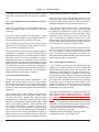
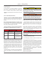
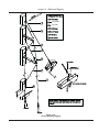
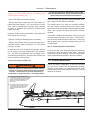
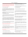
Download 41 Operator`s Manual.. - Marlow
Transcript
Operator's Manual H41 V1.021507 • P/N 1031381 Hunter 41 • Operator's Manual Thank You! From the General Manager Dear Hunter Owner, Congratulations and welcome to the Hunter family! As a Hunter owner, you will enjoy the quality and the attention to detail for which Hunter Boats are renowned. Hunter and your dealer are committed to your service and total satisfaction. This Operator’s Manual will acquaint you with the proper operation and maintenance of your new Hunter boat, as well as boating safety, which is our primary concern, whether in ports or at sea. The new boat warranty registration form you signed at the time of delivery will be sent to us by your dealer. This registers the one year warranty and establishes your contact information in our system. It will also activate Hunter's Customer Satisfaction program (CSS), our effort to insure the highest level of satisfaction and enjoyment with your new Hunter. Within a few weeks of delivery you will receive a letter asking you to complete an online questionnaire primarily about your experience with the dealer. Several months later you will receive a second letter asking you to evaluate the boat. We value your opinion and hope that you will take the time to complete both surveys. As you already know, we work with the highest quality equipment manufacturers to supply the components for your boat. To receive full warranty coverage on all the individual components, such as engine, electronics and appliances, be sure to complete and return to the Original Equipment Manufacturers (OEM) warranty cards to activate the individual warranties for these important components. You will find them in the owner's packet that also contains the OEM manuals for this equipment. Please remember all the information contained in the OEM manuals supersedes the information contained in this manual. Finally, if you are new to boating, be certain to learn the proper rules of seamanship to ensure the safety off your passengers. Refer to Chapman's Piloting, Seamanship, and Small Boat Handling Manual for important and useful information concerning this aspect of boating. Attend a safe boating course offered by the United States Coast Guard Auxiliary, United States Power Squadron, or any enterprise experienced in conducting safe boating courses. Thank you for choosing Hunter. I am confident your new boat will provide you and your family with years off enjoyable boating. Mike Williams General Manager B Hunter 41 • Operator's Manual As the owner of a Hunter, you have chosen one of the finest boats money can buy. Hunter Corporation, is one of America’s oldest privately held boating companies. In February 1996 Hunter became an employee ownership company. We continue to be dedicated to giving you a quality boat that will bring you years of enjoyment whether you’re spending a day at the marina or cruising down a waterway. Performance, dependability, safety, and comfort is more than just a catchy phrase at Hunter. It is the basis for every step of design and construction to assure you of many pleasure-filled years of boating. A Proud Heritage With every Hunter, three generations of experience combine with modern engineering and production techniques provide you one of the most affordable, full featured sailing boats in the industry today. From the stem to the stern, every piece of equipment and its placement has been engineered to provide the most seasoned sailer with the best advantage on the water. Hunter has included everything to make ours the most complete sailing vessel on the market today. How to Use this Manual Many people read their operator’s manual from beginning to end when they first receive their new boat. If you do this, it will help you learn about the features and controls for your new boat. In this manual, you’ll find that pictures and words work together to explain things quickly. Table of Contents A good place to look for what you need is in the Table of Contents in the beginning of this manual. It is a list of the chapters and the page number where you’ll find them. Safety Warnings and Symbols In Boating Safety section you will find a number of cautions, warnings, and danger symbols to tell you about things that could hurt you. In this chapter we tell you where the hazards are. Then we tell you what to do to help avoid or reduce them. Please read this chapter carefully, to prevent yourself or someone else from possible injury. Any questions regarding your Hunter ® or this manual contact Customer Service at: Hunter Corporation Route 441, Post Office Box 1030 Alachua, FL. USA 32616 Phone: (386) 462-3077 Fax: (386) 462-4077 e-mail: [email protected] (8am to 5pm EST) 1-800-771-5556 C Hunter 41 • Operator's Manual Operator’s Manual at a Glance 1. Introduction 2. Documents and Forms 3. Warranty 4. Boating Safety 5. Fuel System 6. Underwater Gear 7. DC Electric Systems 8. AC Electric Systems 9. Water Systems 10. Sanitation and Waste Systems 11. Engines and Transmissions 12. Sails and Rigging 13. Getting Underway 14. Maintenance 15. Glossary D Hunter 41 • Operator's Manual How do I prevent Carbon Monoxide buildup? ? . . . . . . . . . . . . . . . . . . . . . pg.4.6 How do I fuel my boat? ? . . . . . . . . . pg. 5.4 How do I drain water from my fuel filters? . . . . . . . . . . . . . . . . . . . . . . . . . . . . . pg. 5.7 How do I remove my battery? . . . . pg. 7.3 How do I connect shore power? . . pg.8.5 How do I disconnect the shore power? . . . . . . . . . . . . . . . . . . . . . . pg. 8.5 How do I start my generator power? . . . . . . . . . . . . . . . . . . . . . . . . . . . . . pg. 8.6 How do I shut down my generator? ?pg. 8.6 How do I operate my air conditioning? ? .. . . . . . . . . . . . . . . . . . . . . . . . . . . . . . pg. 8.6 How do I fill my fresh water tank? pg. 9.2 How do I sanitize my water? . . . . . . . . 9.3 How do I connect dockside water? ?pg. 9.2 How do my bilge pumps work? ? . pg. 10.3 How do I run my macerator pump? ? ..... . . . . . . . . . . . . . . . . . . . . . . . . . . . . pg. 10.4 How do I start my engines?. . . . . pg. 13.3 What to do in case of a fire. . . . . pg. 4.12 Fixing scratches . . . . . . . . . . . . . . pg. 14.3 Periodic maintenance. . . . . . . . . pg. 14.11 Winterization . . . . . . . . . . . . . . . . . pg. 14.8 Lifting and Storing your boatt . . . pg. 14.7 E Hunter 41 • Operator's Manual Table of Contents 1. Introduction 1.1 The Manual Packet 1.2 Your Responsibilities 1.3 Dealers responsibilities 1.4 Sources of Information 1.5 Equipment Manufacturer Manuals 1.6 Warranties 1.7 Hull Identification Number 1.8 Manufacturers Certifications 1.9 Service Parts and Repair 2. Forms Documents and Forms overview Out of Water Inspection In Water Inspection Pre-Departure Checklist After Sailing Checklist Pre-Delivery Service record Float Plan Maintenance Log 3. Warranty Warranty Information Owner Information Card Restrictions to Warranties Warranty registration Sample Form Letter 4. Boating Safety 4.1 Safety 4.2 Carbon Monoxide Hazard 4.3 Other Dangers 4.4 Fire 4.5 Distress Signals Lightning Illustration Interior Arrangement Std V-Berth Interior Arrangement Opt Pullman General Boat Arrangements Dimension and Capacities Deck Hardware List Deck Arrangement Ventilation (Air Conditioning) 1.1 1.2 1.2 1.3 1.3 1.4 1.4 1.4 1.4 1.5 5. Fuel System Fuel Safety Checklist 5.1 Fuels Tanks 5.2 Fuel Supply Lines and Hoses 5.3 Fuel Valves 5.4 Fuel Filters Fuel Filter Reference 5.5 LPG Troubleshooting Fuel System Drawing LPG Arrangement 2.1 2.2 2.3 2.6 2.7 2.8 2.9 2.10 2.11 5.1 5.2 5.3 5.4 5.5 5.5 5.7 5.8 5.10 5.13 5.15 6. Underwater Gear 6.1 6.1 Mechanical Propulsion Components 6.2 6.2 Steering 6.3 6.3 Seawater Pick-up 6.4 6.4 Windlass and Anchoring 6.5 6.5 Bow Thruster Option 6.7 Through Hulls Port & Stbd 6.8 Troubleshooting 6.9 Bottom Through Hulls 6.11 3.1 3.2 3.4 3.5 3.6 3.7 4.1 4.2 4.4 4.10 4.12 4.12 4.15 4.16 4.17 4.18 4.19 4.20 4.21 4.23 F 7. DC Electric 7.1 The DC Electrical System 7.2 Systems and Components 7.3 Operations and Maintenance Troubleshooting 12 Volt DC Lighting 12 Volt Deck Lighting 7.1 7.2 7.5 7.8 7.9 7.11 7.13 8. AC Electric 8.1 Power Supply Components 8.2 Systems and Components 8.3 Operations and Maintenance Troubleshooting AC Electric Arrangement 8.1 8.2 8.4 8.5 8.7 8.9 9. Water Systems 9.1 Dockside Water Supply 9.2 Water Tanks 9.3 Pumps 9.1 9.2 9.2 9.4 Hunter 41 • Operator's Manual 9.4 Pick - ups and Strainers Water Manifold Legend Troubleshooting Fresh Water Arrangement A/C Cooling (Raw Water) 9.5 9.7 9.8 9.9 9.11 10. Sanitary Systems 10.1 Drains and Discharges 10.2 Pumps 10.3 Other Waste Related 10.4 Head System 10.5 Operations and Maintenance Troubleshooting Bilge Pump Layout Waste System System Electric Toilet System Optional Overboard Waste Grey Water System 10.1 10.2 10.3 10.4 10.5 10.5 10.8 10.9 10.11 10.13 10.15 10.17 11. Engines and Transmissions 11.1 Engines 11.2 Transmissions 11.3 Operations and Maintenance Troubleshooting Exhaust System Arrangement 11.1 11.2 11.4 11.4 11.6 11.9 12. Sails and Rigging 12.1 Main Rig Components 12.2 The Mast 12.3 The Boom 12.4 The Sails 12.5 Reefing Instructions 12.6 Reefing Procedure 12.7 Shaking Out a Reef 12.8 Spinnaker (Option) 12.9 The Arch 12.10 Protecting your Rigging 12.1 12.2 12.3 12.4 12.4 12.6 12.6 12.6 12.6 12.7 12.8 13. Getting Underway 13.1 Boarding your Boat 13.2 Starting the Engine 13.3 Getting Underway 13.4 Returning to Port 13.5 Emergency Operations 13.1 13.2 13.3 13.4 13.6 13.6 G 14. Maintenance 14.1 Maintenance Materials 14.2 Exterior 14.3 Interior 14.4 Mechanical Systems 14.5 Periodic Maintenance 14.6 Lifting and Storage 14.7 Fitting out after Storage 14.1 14.2 14.2 14.4 14.4 14.6 14.7 14.9 15. Glossary 15.1 Chapter 1 Introduction H41 V1.021507 • P/N 1031381 Hunter 41 • Introduction Understand and follow the rules of the road; 1.1 The Manual Packet • Learn how to navigate a boat in all sea, and weather conditions; This operator’s manual, along with your owner's packet, has been compiled to help you to operate your boat with safety and pleasure. The Owner's / Operator's Manual: • Register your boat, contact state boating authorities, or the marine dealer for the registration requirements. • Describes basic safety information; Boating Safety courses provide owners and operators with the opportunity to gain knowledge and experience in a variety of skills: • Describes some of the features of your boat; • Describes the equipment on your boat; • Navigation • Seamanship and boat handling • Rules of the Road • Knowledge of federal, state, and local regulations • Weather prediction • Safety at sea • Survival in bad weather • Respect for others on the water • First aid • Radio communication • Distress signals • Rendering assistance to others • Use of lifesaving equipment • Pollution control • Knowledge of the boat and its systems • Seaworthiness • Leaving or approaching a dock mooring • Anchoring and weighing anchor • Beaching the boat and shallow water operations • Towing and being towed • Handling mooring lines and tying up • Procedures for emergencies including fire, flooding, collision, and medical emergencies, etc. • Contains fundamentals of the use of that equipment; • Contains fundamentals of the use of your boat. However, please note that the information in this manual only summarizes more detailed information in the equipment manuals. The summaries are intended to be a convenient reference for daily use. OEM manuals take precedence over the information in the manufactures documents. This information does not give you a course in boating safety, or how to navigate, anchor, or dock your boat. Operating a boat, sail or power, requires more skills, knowledge and awareness than is necessary to operate a car or truck. 1.2 Your Responsibilities Please keep this manual in a dry and secure but readily accessible place and leave it on the boat at all times! Make sure to hand over this manual to the new owner if you decide to sell the boat. Even when your boat is categorized for them, the sea and wind conditions corresponding to the design categories A, B, or C (see the design category example at the end of this section.) can range from strong gale to severe conditions where only a competent, fit and trained crew handling a well maintained boat can safely operate. If this is your first boat of this type or you are changing to a new boat you are not familiar with, please insure that you obtain handling and operating experience before assuming command. For your safety, and the safety of your passengers you must: We would like to hear your comments or suggestions concerning our manuals. Did you find the information helpful? Was the information delivered in a clear precise manner? Was the information thorough enough to help you with your new boat? Please call us at (904) 8272055 to speak to our Manual Department, if you have questions, or comments, concerning the manual. Please note, this department does not have design or warranty information you will need to contact those departments for such information. • Take a course in Boating Safety; • Get instruction, or aid in the safe and proper handling of your boat; • Familiarize yourself and your passengers of the locations, and use of all safety, and essential operating equipment. 1.2 Hunter 41 • Introduction An orientation in the general operation and mechanical systems of your boat; Fig. 1.1 Design Categories An explanation of the Hunter CSI Program and Hot Alert process for same. Sea and wind conditions for which a boat is assessed by the International Standard to be suitable, provided the craft is correctly handled in the sense of good seamanship and operated at a speed appropriate to the prevailing sea state. A copy of the Product Delivery Service Record form” completed by you and the dealer during your inspection of the boat; Design Category A (“ocean”) A review of all warranty information and how to obtain warranty service; Category of boats considered suitable to operate in seas with significant wave heights above 4 m and wind speeds in excess of Beaufort Force 8, but excluding abnormal conditions, e.g. hurricanes. The complete Owner’s Packet. If you do not receive these materials, forms, or information, or you have any questions contact your dealer, or call 1-800-771-5556 Design Category B (“coastal”) Category of boats considered suitable to operate in seas with significant wave heights up to 4 m and winds of Beaufort Force 8 or less 1.4 Sources of Information In North America, contact one of the following for Boating courses: Design Category C (“inshore”) • U.S. Coast Guard Auxiliary Category of boats considered suitable to operate in seas with significant wave heights up to 2 m and a typical steady wind force of Beaufort Force 6 or less. • U.S. Power Squadron • Canadian Power and Sail Squadrons Design Category D (“sheltered waters”) • Red Cross Category of boats considered suitable to operate in waters with significant wave heights up to and including 0,30 m with occasional waves of 0,5 m height, for example from passing vessels, and a typical steady wind force of Beaufort 4 or less. • State Boating Offices • Yacht Clubs Contact your dealer or the Boat/U.S. Foundation at 1800-336-2628 REF: EN ISO 12217 Outside of North America, contact your boat dealer, or your government boating agency for assistance. Hunter supplies you with; and recommends that you read the following: 1.3 Dealer's Responsibilities Piloting, Seamanship and Small Yacht Handling (Chapman) Motor Yacht and Sailing P.O. Box 2319, FDR Station New York , NY 10002 In addition to a pre-delivery check and service of your boat, your dealer should give to you: A description and demonstration of the safety systems, features, instruments, and controls of your boat; 1.3 Hunter 41 • Introduction Hunter recommends that you purchase and read the following: info can be found in the Warranty section, chapter 3 of the Operator's Manual. Yachtsman Handbook by Tom Bottomly Motor Yacht and Sailing P.O. Box 2319, FDR Station New York, NY 10002 1.7 Hull Identification Number (HIN) The "Hull Identification Number" located on the starboard aft side, is the most important identifying factor, and must be included in all correspondence and orders. Failure to include it creates delays. Also of vital importance are the engine serial numbers and part numbers when writing about or ordering parts for your engine. Refer to the engine manufacturers manuals for locations of engine serial numbers, and record them for future reference. The Complete Book of Maintenance and Repair by Dave Kendall Doubleday and Co. Garden City, NY 11530 Pleasure Yachting and Seamanship U.S. Coast Guard Auxiliary 306 Wilson Road Oaklands Newark, DE 19711 US-HUNPCXXXDXXX Hull Number format: “US” - country origin, “HUN” - Manufacturer, “C” - length code, “XXX” - hull number, “D” - month code, “X” - year code, “XX” - model year 1.5 Equipment Manufacturer Manuals Hunter purchased various equipment and components from other manufacturers and installed them on your boat while it was being built. Examples include the engines, pumps, and the generator. Most OEMs (Original Equipment Manufacturers) have provided operation and maintenance manuals for your boat’s equipment. Keep OEM manuals with your Hunter Operator's Manual in a safe and accessible place. Be sure to pass them along to the new owner if you sell your boat. 1.8 Manufacturers Certifications As a boat manufacturer Hunter builds their products to guidelines established under the Federal Boat Safety Act of 1971. The act is promulgated by the U.S. Coast Guard who has authority to enforce these laws on boat manufacturers that sell products in the United States. Hunter ensures that all of it's products comply with these laws. NOTE: The OEM manuals take precedence over the Hunter Operator's Manual. If information in the Hunter Operator's Manual differs from that in the OEM manuals, follow the information in the OEM manuals. The NMMA, National Marine Manufacturers Association, provides Hunter with a third party certification. The NMMA is an organization that represents the marine industry and assists manufacturers, boat dealers, marinas, repair yards and component suppliers in areas of legislation, environmental concerns, marine business growth, and state and federal government agency interaction. The third party certification that Hunter participates in, uses well known Standards and Recommended Practices of the ABYC, American Boat and Safety Council. 1.6 Warranties Nearly all OEM equipment has its own limited warranties. Warranty registration cards are in your Operator’s packet. We at Hunter participate extensively in the ABYC, which is all non-profit, and develops and publishes voluntary standards and recommended practices for boat and equipment design, construction, service and repair. We utilize all applicable ABYC standards in the construction of Hunter boats. Locate and read the individual warranties; put them together for easy, future reference. For international owner's; your warranty can be found in your CE compliant Owner's Manual. Finally Hunter sells their products worldwide, and as such must conform to the various rules and regulations required by other countries. Most notably are the ISO For U.S. and non-EU compliant countries, your warranty 1.4 Hunter 41 • Introduction standards in Europe which require the application of the CE (Common European) mark. This mark, much like the NMMA certification here in the U.S., gives you the boat owner specific information concerning your boat. 1.9 Service, Parts, and Repair for your Boat When your boat needs serviced, parts, or repair, take it to an authorized Hunter dealer. To find a dealer in your area call 800-771-5556, or internationally you can call 01-305-824600 To find repair and parts facilities for the equipment installed on your boat, refer to the manual for that component. If a problem is not handled to your satisfaction: Discuss any warranty related problems directly with the service manager of the dealership or your sales person. Give the dealer an opportunity to help the service department resolve the matter for you. If a problem arises that has not been resolved to your satisfaction by your dealer, contact Hunter at 800-7715556, and the appropriate customer service department information will be provided to you. 1.5 Hunter 41 • Introduction Notes: 1.6 Chapter 2 Documents and Forms Hunter 41 V1.021507 • P/N 1031381 Hunter 41 • Documents and Forms Your Hunter dealer completes the Pre-Deliveryy Inspection p Report p (Fig. 2.1) before you take delivery of your boat. It is the dealer’s responsibility to both you and to Hunter to give your boat a final inspection. The purpose of this inspection is to assure proper adjustment and operation of the entire vessel. Your dealer should provide you with the Pre-Delivery Inspection Report at the time of delivery. You can get more copies of the report by calling the U.S. Coast Guard Boating Safety Hotline at 1-800-368-5674. You must file this report with the U.S. Coast Guard within 48 hours after an accident resulting in one of the following: A person disappears from a vessel under circumstances that indicate death or injury Hunter will not pay warranty costs for items that should have been covered in the pre-delivery service inspection and recorded on the Pre-Delivery Inspection Report. Personal injury requiring medical treatment beyond first aid Owners must coordinate with the dealer to insure Hunter warranty registration is completed and returned to Hunter. Inserted at the end of this section are several records you will find helpful. Damage to the vessel or property damage Complete loss of the vessel State statutes determine whether you must file an accident report in this case. An accident report must be filed if the damage exceeds a threshold dollar value as established by the states, the threshold is $100-$200. Call the Boating Safety Hotline (800-368-5647) to verify the threshold for a particular state. Use the BOAT RECORD (Fig. 2.2) to record all important information about your boat and its equipment. After your dealer has recorded all the information, remove the record from your Owner’s Manual and store in a safe place. Do not keep this form aboard your boat. Note: State and local agencies may also have accident reporting requirements. Check with local enforcement agencies or with your local Hunter dealer regarding local requirements. The FLOAT PLAN (Fig 2.4) provides a record of your destination, departure and return times, boat description, passenger list, and other information about the trip you have planned. At the bottom of the form is space for listing emergency phone numbers in case your return is delayed past the expected time. It also has space for indicating information about the person filling the report. Leave the completed form ashore with a responsible person. We recommend you make several copies of this form each boating season to make sure you have a good supply. All Hunter boats are built in compliance with applicable United States Coast Guard regulations and recommendations at the time of construction. Hunter boats comply with the standards developed by the National Marine Manufactures Association (NMMA) for its Boat Certification Program. The MAINTENANCE LOG (Fig 2.5) helps to keep maintenance records in one place. Using this log will allow you to track maintenance work that has been completed and to determine when maintenance is required. Your dealer will also find this information helpful. If you decide to sell your boat, the maintenance record will make your boat seeable because it tells prospective buyers that you have taken good care of your boat. The locator drawings will help you find the location of devices and equipment. The ACCIDENT REPORT, T No one likes to think about having a boating accident, but boating accidents do happen. You must file an accident report after a boating accident just as you must file an accident report after an automobile accident. A copy of the U.S. Coast Guard Accident Report is included at the end of this section. On the next few pages you will find sample forms for some of the issues dealing with your new boat. Familiarize yourself with these forms, use them, they can be very handy. NOTE: Efforts have been made to make the drawings in this manual consistent with production. However, in the effort to improve this vessel, modifications have been made in the design that may date some of the drawings in this manual. 2.2 Hunter 41 • Documents and Forms Dear Hunter Owner, Attached you will find a list of items and recommendations that we believe should be incorporated into your own ongoing list of preventative maintenance items and safety check points. THIS LIST SHOULD NOT BE CONSIDERED A COMPLETE SERVICE MANUAL OR THE ONLY ITEMS ON YOUR BOAT IN NEED OF ROUTINE MAINTENANCE, INSPECTION OR ATTENTION. You will find that we address commonly found optional equipment items installed on Hunter boats, as well as most standard equipment from Hunter Marine. Owner’s need to familiarize themselves with individual equipment manuals on all such items, especially aftermarket purchases or optional equipment installed by your dealer or Hunter Marine. This should insure that you are following the manufacturer’s recommendations for proper maintenance and up-keep. We strongly recommend that all owners complete a Power Squadron course followed with a complementary boat inspection before leaving the dock. To locate a Power Squadron in your area please visit < www.usps.org >. Reviewing and familiarizing yourself with the Chapman’s Piloting Manual is also highly recommended for every boat owner. This manual contains demonstrations for safety drills which should be practiced routinely, dealing with adverse conditions, general boat handling and recommended safety equipment. Our opinion is that no boat owner should operate a boat without first reviewing this manual and without having ready access to it while sailing. We hope that this list will be beneficial to you in your ongoing maintenance and upkeep. Safe boating! Thank You Hunter Marine 2.3 Hunter 41 • Documents and Forms Preliminary care and maintenance checklist A qualified Technician should be used if you are not completely confident in your ability to make repairs or inspections. Out of Water Inspection Pre-launch inspection ____ Sacrificial zinc anodes installed ____ Propeller installed with keyway, nuts and cotter pin ____ Propeller shaft turns freely and without excess wobble ____ Struts and shaft log free of corrosion ____ Rudder swings easily & correct with wheel direction ____ Rudder and post inspected for cracks and/or concealed damage (may require removing rudder) ____ Auxiliary tiller handle properly aligned, fits securely and operational ____ All thru-hulls and valves below water line inspected for corrosion, labeled and closed until after launch ____ Bottom paint in satisfactory condition ____ Hull freshly cleaned and waxed (free of gelcoat damage) ____ Mooring, safety lines and fenders onboard and in good condition ____ House & engine start batteries installed and filled with correct electrolyte levels ____ House & engine start battery boxes secured ____ All battery terminals clean and wires secured ____ Engine block & transmission drains closed ____Speed / Depth transducers in place. Speed paddle wheel rotates smoothly ____ Hose clamps on all systems below water line tight ____ Keel bolts tight and clean ____ Exhaust hose attached and secured ____ Boat is free of internal and external water leaks above water line (Failure to stop water intrusion could result in permanent damage or deterioration of structural coring materials, internal wiring and cause mildew and molding) Mast Assembly ____ Review manufacturers manual for maintenance and up-keep ____ Spreaders securely fastened ____ Mast and spreaders free of corrosion and stress cracks ____ Standing rigging and pins inspected for wear, tear, corrosion and cracking ____ External wiring secured for anchor, steaming and deck lights ____ Electronic wind indicator installed per manufacturers recommendation ____ Manual wind indicator installed on masthead ____ VHF antenna installed and connected ____ Headsail furling system installed inspected per manufacturers recommendation ____ Running rigging inspected for wear and tear ____ Mast step stand-up blocks secured and operational ____ Main Sail, jib sail and flaking system inspected for wear and tear (non-furling mast). ____ In- mast system checked for smooth operation and overall condition of sails ____ Specified pre-bend and diagonal tensions attained in mast. See owners manual ____ Mast to deck wiring properly sealed with drip loop 2.4 Hunter 41 • Documents and Forms Anchor System and Ground Tackle ____ Anchor windlass inspected per manufacturers recommendation ____ Anchor secured in bow roller assembly ____ Spare anchor onboard and accessible. ____ See Chapman’s Manual for recommendations on anchors, anchor lines and drogues ____ Anchor line pays out and retrieves into anchor locker without difficulty ____ Bitter end of anchor line secured ____ Anchor rode inspected and free of abrasions ____ Anchor chain shackle lock-wired at pin after secured to anchor and corrosion free ____ Anchor locker hatch secures properly with anchor and line in place ____ Anchor locker free of debris inside ____ Anchor locker drains open Fuel System ____ Tank fuel level indicator functioning properly ____ Fuel clean and treated with engine manufacturers recommended additives ____ Primary and secondary filters cleaned or replaced ____ Fuel tank supply valves open ____ Fuel tank vent clear from tank to atmosphere (hose has anti-siphoned loop in place at hull or deck side) Steering System ____ Inspect and service steering system according to manufacturer’s recommendation ____ Clean and grease autopilot drive chains ____ Ensure compass light is operational Primary Pumps Functional ____ Manual bilge pumps ____ Electric bilge pumps and float switches (discharge hose has anti-siphon loop in place to prevent back flow under sail) ____ Macerator pumps ____ Fresh water pumps ____Toilet flush pumps ____ Shower sump pumps ____ High water bilge alarm pump Illumination and small electrical components check ____ Bow light ____ Cabin lights ____ Stern light ____ Deck light ____ Instrument lamps ____ Masthead light ____ Chart light ____ Anchor light ____ Courtesy lights ____ Reading lights ____ Distribution panel lights 2.5 Hunter 41 • Documents and Forms ____ Smoke detectors operational ____ CO detectors operational (one per cabin recommended) ____ Engine & generator room blower operational ____ Auto fire suppression system operational (engine compartment) ____ Shore power cord and adapter plug operational. See manufacturer’s manual for complete details ____ 110 or 220 VAC outlets operational - Ground fault circuits functioning ____ 110 or 220 VAC inverter/battery charging systems functioning properly ____ Cockpit control systems operational Fresh Water Systems ____ Hot water heater drains shut ____ All spigots and hose bibs shut ____ All tanks flushed clean and free of debris and antifreeze ____ Water heater tank and lines flushed of antifreeze ____ All water lines and components purged of air and checked for leaks ____ Sinks and drains checked for leaks and adequate flow ____ Cockpit shower operational ____ Fresh water filters clean ____ Tank water level indicator systems operating- labeling and tank valve selection correspond Head and Holding Tank Systems ____ Vent clear from tank to atmosphere ____ Filled with fresh water and test pumped with macerator ____ Toilets flush to holding tanks properly ____ Waste level indicating system properly functioning ____ No leaks at any hose fitting within the system Galley Systems ____ Gas bottle filled installed and connected to regulator. Inspect Gas system for leaks after 3 minutes. Should a leak be detected immediately close the main valve exit boat and seek professional assistance for a thorough inspection. ____ Stove and oven operational. Refer to manufacturer’s manual for proper operation and trouble shooting. ____ Gimbal latch secure and operational ____ LPG stowage locker drain open and tank storage area free of derbies. ____ Microwave operational ____ Refrigerator operational and proper temperature attained ____ Freezer operational and proper temperature attained ____ USCG waste disposal-warning poster onboard or in owner’s package ____ Icebox drains to sump or bilge properly ____ Icebox drain plugs installed Topside Inspection ____ Swim seats / ladders / gates operational ____ Swim seat latch operating correctly ____ Cockpit hatches operate properly (adjustments should be made with boat in water) ____ Canvas properly cleaned and installed ____ Cockpit cushions cleaned and installed ____ Lifeline fittings tight and secure 2.6 Hunter 41 • Documents and Forms ____ Rubrail sealed secured to hull ____ Sliding hatches drains free of debris ____ Companionway drop-ins fit properly in companionway and stowage rack ____ Load bearing hardware securely fastened. This includes but is not limited to chainplates, winches and handrails ____ Traveler arch securely fastened. Stainless Steel models should be properly grounded See owners manual for details ____ Plexiglas hatches, ports, windscreens and windows adjusted and cleaned. Cleaners and polishers specifically for Plexiglas can be purchased from most marine supply stores ____ External teak cleaned and oiled (Teak decking cleaned with mild soap and water) ____ External railings cleaned with soap and water then hand polished using automotive wax ____ All deck fill caps seal properly and have retainer chains intact (except Waste Pump-out) ____ Dorade vents or sealing caps installed ____ Topside surface clean and free of gelcoat damage Interior Inspection ____ Drop-in hatches for bunks and floors in place and fit securely ____ Interior steps and grab rails secured ____ Bilges clean and free of debris ____ Opening port and hatch screens in place ____ Blinds / privacy curtains, shades and interior cushions cleaned, installed and secured ____ All doors open / shut / latch properly ____ Insure all wires and connection on distribution panels are tight (should be professionally inspected) ____ Television / VCR operational ____ Stereo / Tape / CD operational ____ Chapman’s Manual onboard and readily available ____ Safety gear onboard readily available and up to date. See Chapman’s Manual and US Coast Guard website at < www.uscg.mil >for details. ____ Boat owner’s manual onboard In Water Inspection Dockside inspection of Engine, Pre-start sequence and operating system ____ Review engine manual for maintenance requirements and proper starting procedure ____ Propeller shaft properly aligned (per engine manual) ____ Shaft to engine coupling bolted and properly torque (per engine manual) ____ All engine mounting bolts in place and properly torque (per engine manual) ____ Crankcase oil at full mark (per engine manual) ____ Transmission fluid / oil at full mark (per engine manual) ____ Coolant mix ratio proper - heat exchanger and expansion tanks full (per engine manual) ____ Seawater intake valve open and no leaks ____ Air bled from fuel lines and system ____ No fuel leaks at any fittings ____ Throttle linkages smooth and operational ____ Shutdown system operational ____ USCG Oil Discharge warning poster in place ____ Exhaust elbows and hoses tight ____ Starting sequence and alarms correct ____ Oil pressure acceptable (per engine manual) ____ Coolant temperature acceptable (per engine manual) 2.7 Hunter 41 • Documents and Forms ____ Alternator DC output at rated rpm (per engine manual) ____ Correct Idle rpm (per engine manual) ____ Water discharged with exhaust ____ Hour meter operational ____ Fuel level indicators operational ____ Throttle cable tension set properly ____ Shifter operation correct ____ Neutral safety start switch operational ____ No inboard exhaust gas leaks ____ No fuel / oil / water leaks on engine ____ Shaft packing / Drip free Seal adjusted and locknuts tight. One to three drips per minute with shaft turning on traditional packing assembly ____ Engine box installed and secured Dockside inspection of Generator, Pre-start sequence and operating system ____ Review and follow manufacturer’s manual for maintenance and up-keep ____ Seawater strainer water-tight and clean ____ No leaks in fuel system - Fuel filters clean ____ Lube oil at full mark ____ Coolant level full - proper mix ratio with water (per generator manual) ____ Seawater discharge overboard with exhaust gas ____ No inboard water or exhaust gas leaks ____ Proper voltage output to distribution panel (per generator manual) ____ Ship / Shore power transfer panel function properly ____ Starter battery box secured ____ Starter battery cable connections clean and tight ____ Starting battery electrolyte level proper Climate Control System ____ Review and follow manufacturers manual for maintenance and up-keep ____ Seawater strainer water tight and clean ____ Seawater pump air purged and operational ____ Seawater flow adequate fwd and aft ____ Fwd system functions properly in all modes of operation ____ Aft system functions properly in all modes of operation ____ No seawater leaks in system components and lines ____ No condensation leaks to deck or liner ____ Air return/intake filters clean and clear ____ 110 or 220 VAC shore power wired correctly at dock ____ Remote control units and display features operate correctly ____ Condensation drains open Pre-departure Checklist ____ Check bilge for extra water ____ Check weather conditions and tides ____ Check food Supply ____ Foul weather gear ____ Linen, sleeping bags ____ Fuel 2.8 Hunter 41 • Documents and Forms ____ Water ____ Sunscreen and sunglasses ____ Tools ____ Docking and anchoring gear ____ Check radio operation ____ Navigation charts and instruments ____ Float plan to a friend or Coast Guard ____ Fuel for Stove ____ Cooking and eating utensils ____ check battery water level ____ oil level, tight V-belts ____ Check for loose electrical connections in the engine compartment ____ Secure loose tools or equipment in the engine compartment so as to not get fouled in the engine. ____ AC systems off, electrical cord stowed ____ Doors and drawers secure ____ Check steering lock to lock ____ Check mast for rigging irregularities and tightness ____ Halyards and sheets are ready to run ____ no lines or obstructions near propeller or bow ____ Anchor ready to run ____ Check lifelines for tightness ____ Turn on waterlines ____ Stow all loose gear ____ Open engine cooling water thru intake valve After Sailing Checklist When leaving your Hunter at the dock for more than a short time, it is a good idea to review the following checklist to make sure everything is in order. This will help protect the various parts of your boat and add considerably to their attractiveness and usable life. ____ Flake or furl mainsail and cover, or remove and bag. ____ Remove and stow all portable deck hardware such as snatch blocks, winch handles, etc. ____ Secure the boom to the topping lifts and set it firmly amidships with the main sheet purchase. (It is also a good idea to rig a line from the steering wheel or tiller to a convenience cleat to keep the rudder from swinging back and forth with the motion of the water or employ the wheel brake if so equipped.) ____ Attach the shackle ends of all halyards to convenient fittings and take up slack. Find a location leading away from the mast to keep the halyard from slapping the mast. ____ Coil and stow all lines in line lockers ____ Cover the winches and steering pedestal when leaving the boat for several days or more ____ Close all fuel lines and seacocks ____ Switch off the electrical system ____ Pump out the bilge ____ Check air vents, secure ports and hatches, swab the deck, and clean deck stainless, particularly if you have operated in salt water. 2.9 Hunter 41 • Documents and Forms Fig. 2.1 Pre-delivery Service Record DEALER: _____________________________ ENGINE:_________________________________ MAKE:_______________________________ OWNER: ________________________________ PORT ENGINE NO: ____________________ STBD. ENGINE NO: _______________________ BOAT A NAME:__________________________REGISTRY R NO:_________________________ ___ INITIALS_________ OPERATION___________INITIALS________ A OPERATION____________ A BEFORE LAUNCHING BEFORE STARTING T ENGINES 1. Hull Side Clean and Gelcoat 2. Bright work clean and finish 3. Decks cleaned and gelcoat 4. Interior Finish 5. Upholstery clean and carpet in place 6. Bilge cleaned. 7. Bottom clean and paint 8. Both shafts turn freely 9. Engines and Generator intakes installed 10. All hull fittings sealed 11. All drain plugs tight, (hull, engines, generator, muffler) 12. Sacrificial Anodes installed10 23. All engine wiring in good order & tight A IN W WA ATER WITH BOAT 13. Hose test for cabin and window leaks 14. No water leaks at thru hull fitting with seacocks 15. No water leaks at shaft or rudder 24. Throttle control and cable travel 25. Clutch control and cable travel 26. Crankcase oil level at FULL mark 27. Reverse gear oil level at FULL mark 28. No fuel leaks in fuel lines, at fittings, at fuel filter, fuel pump 29. No engine water or oil leaks 30. Oil pressure and exhaust water flow 31. Idling speed set at 700-800 RPM and is in proper adjustment WATER TEST BOAT WA A 33. Engine performance 34. Instruments are registering properly 35. T Top RPM wide open throttle for one minute after warm-up 36. Boat performance 16. With all switches off f - no spark when battery cable touched to post 17. All electrical equipment operating including: horn( ); running light( ); bilge pump( ) FINAL CHECK: 18. Toilet T operates 37. All accessory equipment operating 38. Carpets and drapes installed and clean 39. All loose equipment on boat ready for new owner. 19. Water (pressure) system operates 20. Galley stove operates 21. With fuel tanks full, no fuel leaks at fill pipes, overflow vent, or at any fuel line connections 22. With coupling disconnected, engine and shaft alignment INSPECTION DATE:____________________ A ___ DEALERS SIGNATURE: _______________________________________________________ OWNERS SIGNATURE: A ___________________________________________________________ COMMENTS:____________________________ __________________________________________ _______________________________________________________________________________ 2.10 Hunter 41 • Documents and Forms Float Plan Name of Operator____________________________________________________Age____________________ Address____________________________________________________________________________________ Phone______________________________________________________________________________________ Boat Make ________________________________ Model__________________________________ Length _______________________ Hull Color_________________Deck Color___________________________ Registration No._____________________________Home Port________________________________________ Radio frequencies____________________________________________________________________________ Equipment on Board, PFDs, Flares, Anchor ______________________________________________________ ___________________________________________________________________________________________ Fuel Capacity ______________________________ Water Capacity____________________________________ Distinguishing Features________________________________________________________________________ ____________________________________________________________________________________________ Departed from_______________________________________________________________________________ Date____________________________________________ Time________________________________________ Destination__________________________________________________________________________________ Stops_______________________________________________________________________________________ Estimated time of Arrival: Date_______________________Time________________________________________ Name, age, address and phone number of other persons on board: _______________________________________________________________________________________ _______________________________________________________________________________________ _______________________________________________________________________________________ _______________________________________________________________________________________ _______________________________________________________________________________________ _______________________________________________________________________________________ 2.11 Hunter 41 • Documents and Forms Maintenance Log Date Maintenance Performed 2.12 Hourmeter Hunter 41 • Documents and Forms Maintenance Log Date Maintenance Performed 2.13 Hourmeter Hunter 41 • Documents and Forms (Several copies may be required to complete each of the following categories) Chapman’s Piloting recommended operating techniques, maintenance inspections and safety points for my particular boat length and type of sailing 2.14 Hunter 41 • Documents and Forms Recommendations made by manufacturers of original equipment for proper maintenance and up-keep 2.15 Hunter 41 • Documents and Forms Power Squadron recommendations for maintenance and safe boating 2.16 Hunter 41 • Documents and Forms Local sailing club or marina’s recommendations for maintenance and up-keep 2.17 Hunter 41 • Documents and Forms List of onboard safety equipment and location (A copy should be posted onboard at all times) 2.18 Hunter 41 • Documents and Forms Spare Parts List 2.19 Hunter 41 • Documents and Forms Dates of practice drills and onboard safety inspections 2.20 Hunter 41 • Documents and Forms My personal preferences for maintenance items & safety gear 2.21 Hunter 41 • Documents and Forms Notes: 2.22 Chapter 3 Warranty Hunter 41 V1.021507 • P/N 1031381 Hunter • Warranty This Page Intentionally Left Blank 3.2 Hunter • Warranty Your Hunter Warranty Hunter offers a limited warranty on every Hunter boat sold through an authorized Hunter dealer. A copy of this warranty is included here, and in your Operator's Manual. If for some reason you are not able to understand, read, or view this manual, please contact your local dealer for a replacement copy. We stand behind the quality of your boat with our limited warranty, which you should review. To insure the operation and validity of your limited warranty, please complete the attached card and send it to us within ten (10) days of the purchase date. Section 15 of the U.S. Federal Boat Safety Act requires registration of a boat’s first owner. The warranty data should also be recorded in the space below for your own reference. The following warranties apply to all 2008 Model Year boats produced by HUNTER MARINE CORPORATION: LIMITED ONE-YEAR WARRANTY Hunter Marine warrants to the first-use purchaser and any subsequent owner during the limited warranty period that any part manufactured by Hunter will be free of defects caused by faulty workmanship or materials for a period of twelve (12) months from the date of delivery to the first-use purchaser under normal use and service. During this period, as the sole and exclusive remedy, Hunter’s obligation under the warranty is limited to the repair or replacement of any such defective part. LIMITED FIVE-YEAR HULL STRUCTURE AND BOTTOM BLISTER WARRANTY Hunter warrants to the first-use purchaser and any subsequent owner during the limited warranty period that the hull of each boat will be free from structural defects in materials and workmanship for a period of five (5) years from the date of delivery to the first-use purchaser under normal use and service. This limited warranty applies only to the structural integrity of the hull and the supporting pan/grid or stringer system. Hulls, pan/grid or stringers modified in any way or powered with engines other than the type and size installed or specified by Hunter are not covered by this limited warranty. As the sole and exclusive remedy, Hunter’s obligation under the warranty is limited to repair or replacement of any such defective part. 3.3 Hunter • Warranty Hunter also warrants to the first-use purchaser and any subsequent owner during the warrantyy period that the boat will be free from gelcoat blistering on underwater surfaces of the hull, exclud-ing the keel and rudder, for a period of five (5) years from the date of delivery to the first-use e purchaser under normal use and service. During this period, Hunter will supply or reimburse an n authorized Hunter dealer for all of the parts and labor required to repair a blistered underwaterr surface of the hull. The labor cost reimbursement will be based on the Labor Allowance Schedule e established by Hunter from time to time, however if the repair is performed by a non-Hunter dealer, the repair cost must be authorized by Hunter in advance and be based on a reasonable numberr of hours as determined by Hunter. Hunter will not pay transportation, hauling, launching, bottom m paint, storage, dockage, cradling rental, rigging and derigging, or other similar costs. It is recom-mended that the repair be done during a seasonal haul out for service or storage. PLEASE KEEP THIS MANUAL IN A SAFE PLACE AND HAND IT OVER TO THE NEW OWNER IF YOU SELL THE CRAFT. You should also complete the warranty cards for your engine, stove, head, electric water pump and other accessories. These are enclosed in the manufacturers’ manuals that are packaged with your owner’s manual. HUNTER EXPRESSLY DISCLAIMS THE IMPLIED WARRANTIES OF MERCHANTA BILITY AND FITNESS. NEITHER HUNTER OR THE SELLING DEALER SHALL HAVE ANY RESPONSIBILITY FOR LOSS OF USE OF A BOAT, LOSS OF TIME, INCONVENIENCE, COMMERCIAL LOSS, OR CONSEQUENTIAL DAMAGES. 3.4 Hunter • Warranty The following circumstances will void the bottom blister limited warranty: (1) If the gel-coat has been sanded, sandblasted, or subjected to abrasion or impact. (2) If the instructions provided in the Hunter Owner’s Manual are not followed according to Hunter’s required bottom preparation procedures. RESTRICTIONS APPLICABLE TO WARRANTIES These limited warranties do not cover: (1.) Paint, window glass, Gelcoat, upholstery damage, plastic finishes, engines, engine parts, bilge pumps, stoves, blowers, pressure water pumps, propellers, shafts, rudders, controls, instruments, keels and equipment not manufactured by HUNTER. Any warranty made and issued by the manufacturer of such items will be, if and where available, provided to the first use purchaser. (2.) Problems caused by improper maintenance, storage, cradling, blocking, normal wear and tear, misuse, neglect, accident, corrosion, electrolysis or improper operation. (3) Boats used for commercial activities including charter. THESE LIMITED WARRANTIES ARE YOUR SOLE AND EXCLUSIVE REMEDIES AND ARE EXPRESSLY IN LIEU OF ANY AND ALL OTHER REMEDIES AND WARRANTIES EXPRESSED AND IMPLIED, INCLUDING THE WARRANTIES OF MERCHANTABILITY AND FITNESS FOR A PARTICULAR PURPOSE, WHETHER ARISING BY LAW, CUSTOM, CONDUCT, OR USAGE OF TRADE. SOME STATES DO NOT ALLOW LIMITATIONS ON HOW LONG AN IMPLIED WARRANTY LASTS, SO THE ABOVE LIMITATION MAY NOT APPLY TO YOU. IN THE EVENT THAT IMPLIED WARRANTIES ARE FOUND TO EXIST UNDER THE LAW OF A PARTICULAR STATE, NOTWITHSTANDING THE EXCLUSION CONTAINED HEREIN, THE DURATION OF ANY SUCH IMPLIED WARRANTY SHALL BE LIMITED TO THE DURATION OF THE APPLICABLE LIMITED WARRANTY STATED HEREIN. THE PURCHASER ACKNOWLEDGES THAT NO OTHER REPRESENTATIONS WERE MADE TO HIM OR HER WITH RESPECT TO THE QUALITY OR FUNCTION OF THE BOAT. ANY ORAL STATEMENT OR PRINTED MATERIAL ADVERTISING THE BOAT WHICH SPEAKS TO ANY PERFORMANCE CHARACTERISTIC OF THE BOAT OR ANY OF ITS COMPONENTS SHALL BE CONSIDERED AND CONSTRUED AS AN ESTIMATED DESCRIPTION ONLY AND SHOULD NOT BE RELIED UPON AS AN EXPRESS WARRANTY OR AS THE BASIS OF THE BARGAIN FOR THE BOAT OR ANY OF ITS COMPONENTS. ANY CONSEQUENTIAL, INDIRECT OR INCIDENTAL DAMAGES WHICH MAY BE INCURRED ARE EXCLUDED AND PURCHASER’S REMEDY IS LIMITED TO REPAIRS OR REPLACEMENT OF ANY SUCH PART(S). SOME STATES DO NOT ALLOW THE EXCLUSION OR LIMITATION OF INCIDENTAL OR CONSEQUENTIAL OR INDIRECT DAMAGES, SO THE ABOVE LIMITATION OR EXCLUSION MAY NOT APPLY TO YOU. THIS WARRANTY GIVES YOU SPECIFIC LEGAL RIGHTS, AND YOU MAY ALSO HAVE OTHER RIGHTS WHICH VARY FROM STATE TO STATE. 3.5 Hunter • Warranty OWNER INFORMATION CARD HULL IDENTIFICATION NUMBER IS ON THE STARBOARD AFT SIDE OF THE HULL OR TRANSOM. THIS NUMBER MUST BE GIVEN IN ALL NECESSARY CORRESPONDENCE. HULL NO. DATE DELIVERED TO OWNER YACHT NAME OWNER NAME STREET ADDRESS CITY STATE/COUNTRY ZIP CODE HOME PORT ENGINE MODEL SERIAL NO. PROPELLER SIZE DEALER PHONE STREET ADDRESS CITY STATE/COUNTRY CUSTOMER SERVICE / WARRANTY 3.6 ZIP CODE Hunter • Warranty WARRANTY REGISTRATION These limited warranties shall not be effective unless the HUNTER Warranty Registration Form and Pre-Delivery Service Record, which are furnished with each new boat, are filled out completely and re-turned to HUNTER within ten (10) days of delivery. Return of the Warranty Registration Form to HUNTER, signed by both Dealer and Owner, is critical. Warranty coverage cannot be initiated until the completed form is received at HUNTER. All repairs and/or replacements will be made by an authorized Hunter dealer, or at the option of Hunter, at the Hunter plant. If the repairs are of such a nature that the warranty work must be performed at the HUNTER plant, transportation costs to and from the HUNTER plant shall be paid by the owner. The labor cost reimbursement will be based on a Labor Allowance Schedule established by HUNTER and where not applicable, on a reasonable number of hours as determined by HUNTER. Any repairs and replacements must be approved in advance by an authorized HUNTER service representative. TRANSFER OF LIMITED WARRANTIES For 1995 and later hull numbers, the limited warranties will be transferred to a subsequent purchaser of the boat if: (1) A notice of the transfer of ownership of the boat is given by the subsequent purchaser in writing to Hunter within thirty (30) days of the transfer. (2) The notice shall include the name, address and telephone number of the subsequent purchaser, the date of purchase, the hull number and the name of the seller of the boat. Hunter will mail to the subsequent purchaser notice of the expiration dates of the limited warranties (see form letter, attached). The transfer of the ownership of the boat will not extend the expiration dates of the limited warranties. CUSTOMER SATISFACTION SURVEYS During the first year of ownership, the first purchaser will receive two Customer Satisfaction Surveys - the first (CSS#1) will be received shortly after taking delivery and focuses on the dealer’s ability to sell and commission the boat, and the Owner’s initial satisfaction. The second survey (CSS#2), nine to ten months into ownership, “measures” dealer service capability and allows the owner to evaluate most of the boat’s functional systems and characteristics. Both surveys are dependent upon receipt of the first purchaser’s Warranty Registration Form. 3.7 Hunter • Warranty SAMPLE FORM LETTER March 12, 1997 Mr. John Smith 1456 Joy Street Sarasota, FL 34266 Dear Mr. Smith, SA M PL E Thank you for providing written notice of transfer of ownership. We are pleased you have selected a Hunter sailboat and we will make every effort to assure Hunter ownership will be a satisfying experience for you. Based on the information you have provided, we are pleased to notify you of the expiration dates of the limited warranties. • The limited one-year New Boat warranty expires (d)_____________________. • The limited five-year Hull Structure and Bottom Blister warranty expires (d)__________. Should you require assistance at any time during ownership, we encourage you to contact your Hunter dealer or to call us directly at 386-462-3077. Please confirm the information at the bottom of the page and advise us if any corrections are required. _____________________________________ Customer Service Manager -------------------------------------------------------------------------------------------------------------------------------Hull No: HUN__________________________Model:__________________________________ Telephone: (H)________________________(B)______________________________________ Date of Purchase:______________________________________________________________ Purchased From: Name:_______________________________________________________ Address:_________________________________________________________ City/State_________________________________Zip_____________________ ( ) Private Owner ( ) Dealer 3.8 Chapter 4 Boating Safety H41 V1.021507 • P/N 1031381 Hunter 41 • Boating Safety As you read your owner’s manual, please note hazard warnings which alert you to safety and precautions and unsafe conditions or operating procedures. We have included these warnings because we are concerned about your safety and the safety of your passengers. Hazard statements generally have five parts: 4.1 Safety Boating safety and the safety of your passengers are your responsibility. You should fully understand and become familiar with the operating and safety procedures and precautions in this manual and the other manuals in the owner’s packet before you launch your new boat. 1. The hazard symbol. 4.1.1 Safe Operation 2. A signal word which indicates the severity of the hazard. Following is general information about safe operation. 3. A concise description of the hazard. Keep your boat and equipment in safe operating condition. Inspect the hull, engines, safety equipment, and all boating gear regularly. 4. The results of ignoring the hazard. 5. Steps for avoiding the hazard: Important: Federal law requires you, the owner, or operator to provide and maintain safety equipment on your new boat. Consult your Coast Guard, state, and local regulations to ensure your boat has all required safety equipment on board. Additional equipment may be recommended for your safety and that of your passengers. Make yourself aware of its availability and use. The three signal words which indicate the severity of a hazard are danger, warning, and caution. The meanings they convey are as follows: ! DA NGER ! BE VERY CAREFUL when fueling your boat. Be sure you know the capacity of your boat’s fuel tank and the amount of fuel you use when operating at frequently used engine speeds (RPMs). Calls attention to immediate hazards that will result in severe injury or death. ! WA R N I N G ! Always know all the area's on the boat, know the nautical terms for the different areas of your boat. On the following page, at the end of this chapter we show you a general layout of these terms and illustrate the areas that may be of importance to you. Identifies hazards or unsafe practices that could result in personal injury or death. ! C AU T I O N ! Indicates hazards or unsafe practices that could result in minor personal injuries, property damage, or component damage. Make sure you have enough fuel on board for anticipated cruising requirements. In general, use 1/3 of your supply to reach your destination and 1/3 to return. Keep 1/3 in reserve for changes in your plans due to weather or other circumstances. Also included in this manual are owner advisory statements identified as "Important" or "Note". Unlike the hazard communication statements, they alert you to conditions affecting equipment operation, maintenance, and servicing practices. Note: Your generator supply line is located higher on the auxiliary fuel tank than the engine’s supply lines. This is for your safety in that your generator cannot deplete your fuel supply should it ever be left running. Important: This is a general advisory statement or procedure intended to prevent damage to the equipment or associated component. Be sure lifesaving and fire extinguishing equipment is on board. This equipment must meet regulatory agency standards, and it should be noticeable, accessible, and in a safe operating condition. Your passengers should know where this equipment is and how to use it. Note: This is a general advisory statement relating to equipment operating and maintenance procedures. Its intent is to call attention to information more important than normal text. 4.2 Hunter 41 • Boating Safety • Keep an eye on the weather. Be aware of possible changing conditions by checking a local weather report before your departure. Monitor strong winds and electrical storms closely. are allowed time to make correction without prosecution. Check with the appropriate state agency or the Coast Guard Auxiliary for details. 4.1.4 Rules of the Road • Always keep accurate, updated charts of the area on board your boat. Navigating a boat is much the same as driving an automobile. Operating either one responsibly means complying with a set of rules intended to prevent accidents. Just as you assume other car drivers know what they are doing, other boaters assume you know what you are doing. • Before you leave the port or harbor, file a float plan with a family member, relative, friend, or other responsible person ashore. • Always operate your boat with care, courtesy, and common sense. As a responsible yachtsman, you will comply with the “Rules of the Road”, the marine traffic laws enforced by the U.S. Coast Guard. There are two sets of rules: The United States Inland Navigational Rules and the International Rules. The United States Inland Rules apply to all vessels inside the demarcation line separating inland and international waters. The Coast Guard publishes the “Rules of the Road” in its publication “Navigational Rules, International-Inland.” You can get a copy from your local U.S. Coasty Guard Unit or the United States Coast Guard Headquarters, 1300 E Street NW, Washington, D.C. 20226. • Instruct at least one other passenger aboard in the operating procedures in handling your boat. This person can take over if you unexpectedly become unable to do so. • Do not allow passengers to ride on parts of your boat other than designated seating areas. • Ask all passengers to remain seated while the boat is in motion. 4.1.5 Safety Equipment • Do not use the swim platform or boarding ladder while engines are running. Important: Federal law requires you, the owner, to provide and maintain safety equipment on your boat. Consult your Coast Guard, state, and local regulations, to ensure your boat has all required safety equipment on board. Additional equipment may be recommended for your safety and that of your passengers. Make yourself aware of its availability and use. • Understand and obey the “Rules of the Road.” Always maintain complete control of your boat. • Do not overload or improperly load your boat. We have provided the following safety equipment in your Loose Gear Kit (Does not apply to UK boats): 4.1.2 Safe Boating Courses Your local U.S. Coast Guard Auxiliary and the U.S. Power Squadrons offer comprehensive safe boating classes several times a year. You may contact the Boat/U.S. Foundation at 1-800-335-BOAT (2628), or in Virginia 1800-245-BOAT (2628). For a course schedule in your area, you may also contact your local U.S. Coast Guard Auxiliary or Power Squadron Flotilla for the time and place of their next scheduled classes. • • • • • • • • • 4.1.3 Voluntary Inspections (3) Fire Extinguishers (2) Stainless Anchor Shackles (1) 250’ Nylon Anchor Line (1) 20’ Galvanized Chain (6) Adult Form Life Vests (PID) (1) White Form Cushion (1) United States Coast Guard Pamphlet (1) Anchor (1) Air Horn 4.1.6. Additional Equipment State boating officials in many states or the U.S. Coast Guard Auxiliary offer courtesy inspections to check out your craft. They check your boat for compliance with safety standards and required safety equipment. You may voluntarily consent to one of these inspections and You should consider having additional equipment on board to help make your boating experience safer and more enjoyable. Some examples include the following: 4.3 Hunter 41 • Boating Safety • • • • • • • • • • • • • • • • • • • Anchor and line * Boat hook* Bucket & Sponge Commonly used spare parts Distress signal kit* Docking lines* Engine and accessory manuals* Extra keys Extra V-belts Fenders* First aid kit Flashlight & extra batteries Manually operated bilge pump Navigational charts Owner’s Manual Replacement bulbs VHF radio Spare fuel and oil filters Tool kit to place themselves in a vertical or face-up position in the water. Type III PFD has the same minimum buoyancy as a Type II PFD. It has little or no turning ability. People participating in water sports often prefer this PFD because it is intended for use in waters where quick rescue is possible and it is generally the most comfortable for continuous wear. (D) PFD Type IV, Throwable: You must also have aboard at least one throwable PFD Type IV device. The Type IV device can be thrown to a person in the water and held by the user until rescued. The design does not allow it to be worn. The most common Type IV PFD are buoyant cushions or ring buoys. This PFD must be immediately available for use and in serviceable condition. 4.2 Carbon Monoxide Hazard *Provided in Loose Gear Kit (US Boats only) 4.1.7 Personal Flotation Devices (PFDs) (See enclosed brochure concerning Carbon Monoxide poisoning and preventing) There must be one United States Coast Guard approved wearable personal flotation device of Type I, II, or III for each person on board your boat. The PFDs must be in serviceable condition and readily accessible. A minimum of three PFDs (two wearable and one throwable) is required regardless of the number of persons on board. As all responsible yachtsmen know, there are unseen dangers when boating. One danger is serious enough that we feel the need to specifically bring it to your attention. It is odorless, colorless, and tasteless, but can be harmful or fatal if inhaled. Its name is CARBON MONIXIDE (CO) (A) PFD Type I, Wearable: 4.2.1 Carbon Monoxide Safety This offshore life jacket has the greatest buoyancy. It is effective for all waters where rescue may be delayed. Its design allows for turning most unconscious persons in the water from face down position to a vertical or face-up position. This section is intended to provide educational information about carbon monoxide relative to boats and boating. Carbon Monoxide accumulation is affected by boat geometry, hatch, window, and door openings, ventilation openings, proximity to other structures and boats, wind direction, boat speed, boat maintenance, and a multitude of other variables. This section discusses many of these and enables the boat owner to better understand all conceivable variables. Therefore, the boat owner is cautioned not to exclusively rely on it to prevent the accumulation of Carbon Monoxide. (B) PFD Type II, Wearable: This near-shore buoyant vest provides less buoyancy than a Type I PFD. It is intended for calm inland waters or waters where there is a chance of quick rescue. It turns its wearer to a face-up position as does the Type I PFD, but the turning action is not as pronounced as the Type I, and it will not turn as many persons under the same conditions as a Type I. 4.2.2 What is Carbon Monoxide? Carbon Monoxide is a highly poisonous gas formed by the combination of carbon and oxygen. Commonly referred to as CO, its chemical formula is C for carbon and O for oxygen. CO is a colorless, odorless, and tasteless gas that, by itself, cannot be detected by human senses. CO (C) PFD Type III, Wearable: Classified as a flotation aid, this PFD allows wearers 4.4 Hunter 41 • Boating Safety diffuses in the air much more rapidly than other gasses that are detectable by the human senses. The weight of CO is about the same as air so it does not rise or fall like other gasses but will distribute itself throughout the boat. CO is produced any time a material containing carbon is burned. In boating, these materials include, but are not limited to, gasoline, diesel fuel, or propane. All carbon based fuels produce varying amounts of CO, depending on their carbon content. Gasoline is high in carbon and, therefore, produces lower levels of CO. However, the exhaust of all engines and generators as well as any open flame device, produce CO and the same precautions should be taken regardless of the type of fuel. Dizziness Vomiting Collapse Nausea Fatigue 4.2.5 Effects of Carbon Monoxide When inhaled, Carbon Monoxide is absorbed by the lungs and reacts with the blood hemoglobin to form carbon hemoglobin, which reduces the oxygen carrying capacity of the blood. The result is a lack of oxygen for the tissues, causing subsequent tissue death and, if prolonged, death of the individual. Carbon Monoxide in high concentrations can be fatal in a matter of minutes. Even lower concentrations must not be ignored because the affects of exposure to CO are cumulative and can be just as lethal. Certain health related problems and age increases the effects of CO. People who smoke or are exposed to high concentrations of cigarette smoke, consume alcohol, or have lung or heart disorders are particularly susceptible to an increase in the effects from CO. However, the health of all of the boat’s occupants should be considered. Physical exertion accelerates the rate at which the blood absorbs CO. The early effects of CO poisoning are easy to overlook because they are similar to the effects of other boating related stress such as eye strain, fatigue, sun exposure, seasickness, or alcohol consumption. But, as the concentration of CO in the air increases, it has increasingly adverse effects on your health. 4.2.3 How Carbon Monoxide Can Enter Your Boat Any device that burns fuel creates Carbon Monoxide. For example, a propane cook-top or a space heater are both potential sources for CO. But the most serious danger comes from the gasoline engines and generators aboard your own and neighboring boats. There are four basic ways that CO from a running engine or generator can enter your boat. The “station wagon effect” results from the aerodynamics of deck cabins and flying bridges. With the boat underway, the air flow over the top forms a low pressure area behind the cabin or transom which can suck exhaust gasses into the cockpit and the cabin inefficient trim angles also can cause the station wagon effect. 4.2.4 Symptoms of Carbon Monoxide Poisoning 4.2.6 When Overcome by Carbon Monoxide Most important is to know the causes, study the symptoms, and be trained in the emergency care. This is the best way to avoid, understand, and respond to any Carbon Monoxide emergency: When someone falls victim to Carbon Monoxide poisoning, fast and responsive action is crucial. Know the symptoms. The earlier the effects of CO are detected, the better the chances for recovery. The following list shows the sequences of events that must be done in an effort to revive a CO victim: • Evacuate, Ventilate, Investigate, complete the Carbon Monoxide poisoning action sequence • Move the victim to fresh air. • Administer oxygen if available. If the victim is not breathing, perform artificial resuscitation per approved CPR procedures until medical help arrives and takes over. Prompt action can mean the difference between life and death. • Ventilate the area. • Investigate the source of CO and take corrective action. One or more of the following symptoms can signal the adverse effects of Carbon Monoxide accumulation. The order of this list is generally the sequence of symptoms. However, the number of symptoms and the order of their appearance may change for different people. Watering and Itching eyes Tightness in the chest Flushed Appearance Ringing in the ears Throbbing Temples Inattentiveness Convulsions Drowsiness Headache 4.5 Hunter 41 • Boating Safety • As always, you can contact the Red Cross to obtain information for training in CPR or emergency response care. before starting the engines or generator. Next, start each engine and generator one at a time. Follow the full run of the exhaust system, listening and looking for leaks. While doing this, make sure there is adequate ventilation and that your CO detector is on. 4.2.7 How to Minimize the Accumulation of Carbon Monoxide Practice good inspection and maintenance habits. Be certain hull exhaust outlets are not blocked or restricted in any way. Other items to inspect are as follows: If your boat has access panels, check that the access panels around the engine and exhaust are in place and fit snugly to minimize the opportunity for CO to enter the cabin. There should be no large openings where CO could enter the cabin. Ensure that all ventilation systems are in good working order and are not blocked or punctured. Check all sink drains to assure that they have a good water trap to prevent CO from coming in from the outside. Be alert for exhaust gasses from other boats. Always provide adequate ventilation when weather enclosures are in place and engines or generator is running. Do not run with a high bow angle. Use trim tabs or redistribute the load to maintain a low bow angle. Orient your boat to maximize the dispersion of CO. Finally, because poorly running engines produce excessive CO, make sure engines and generators are tuned up. They should run smoothly and not produce black smoke. The spark plugs (gas engines) and ignition systems should be maintained regularly, and the fuel system and air filters should be in good order. We cannot identify or describe every possible variable or combination of variables, you must continually observe passengers for symptoms or Carbon Monoxide intoxication and be aware of the many possibilities of Carbon Monoxide accumulation. For instance, poorly maintained hoses and hose connections on the generator or engine exhaust system(s) can permit Carbon Monoxide to escape into the interior of your boat. Therefore, the exhaust system must be periodically examined and maintained in order to ensure its integrity. Moreover, all accommodation spaces constantly require proper ventilation. 4.2.9 Carbon Monoxide Detectors If you carefully avoid potential CO accumulation and maintain your systems properly, you have made great strides towards protecting yourself and others from the dangers of Carbon Monoxide. We have assisted you in your endeavor by providing CO detectors in each living area aboard your boat. We use only those CO detectors that are UL approved for marine use. RV and residential models won’t withstand the elements of the boating environment. Most CO detectors require specific maintenance procedures to remain accurate and functional. Follow the manufacturer’s instructions for the use and maintenance of the CO detectors. 4.2.8 Preventative Maintenance Frequent inspections and proper maintenance of the engine, and exhaust system, as well as, other various areas of your boat are critical in preventing the accumulation of Carbon Monoxide. It is the owner’s responsibility to make sure the entire boat is inspected and maintained against CO. it's strong recommended that you change CO and Smoke alarm batteries when changing the clocks for DaylightSaving Time. Replace Smoke Alarms every 10 years and replace Carbon Monoxide (CO) alarm every 5 years since the sensors in these devices can degrade because of environmental contamination and from age. In addition to replacing batteries in smoke alarms at least once every year. Always make sure the followings: 1. Smoke/CO alarms should be tested monthly to make sure they are working in your boat. 2. Batteries should be changed once a year, when changing the time on clocks of your boat. The exhaust systems of your engines and generator are under constant attack from salt water, gasses, vibration, and normal wear. Inspect every exhaust system component often. Start with a visual inspection. Check each joint for discoloration, carbon buildup, stains, water leaks, or other signs of damage. Inspect all metal parts for corrosion, discoloration, or flaking. Check that all hose clamps are in good condition and properly tightened. Carefully inspect all exhaust and cooling hoses for signs of wear, dry rot, cracking, discoloration, chafing, or swelling. If any of these conditions exist, have the entire system inspected and corrected by a qualified technician 4.6 Hunter 41 • Boating Safety Know the Dangers! Swimming near or under the back deck or swim platform. Carbon monoxide from exhaust pipes of inboard engines, outboard engines and generators build up inside and outside the boat in areas near exhaust vents. STAY A AWA WAY from these exhaust vent areas and DO NOT swim in these areas when the motor or generator is operating. On calm days, wait at least 15 minutes after f the motor or generator has been shut off f before entering these areas. NEVER enter an enclosed area under a swim platform where exhaust is vented, not even for a second. It only y takes one or two breaths of the air in this “death chamber” for it to be fatal. Blockage of exhaust outlets can cause carbon monoxide to accumulate in the cabin and cockpit area - even when hatches, windows, portholes, and doors are closed. Exhaust from another vessel that is docked, beached, or anchored alongside your boat can emit poisonous carbon monoxide gas into the cabin and cockpit of your boat. Even with properly vented exhaust, your boat should be a minimum of 20 feet from the nearest boat that is running a generator or engine. Slow speeds or idling in the water can cause carbon monoxide gas to accumulate in the cabin, cockpit, bridge, and aft f deck, even in an open area. A tailwind (force of wind entering from aft f section of the motorboat) can also increase accumulation. The “station wagon effect,” f or backdrafting f can cause carbon monoxide to accumulate inside the cabin, cockpit, and bridge when operating the boat at a high bow angle, with improper or heavy loading or if there is an opening which draws in exhaust. f can also cause carbon monoxide to accumulate inside the cabin, cockpit, aft f deck, This effect and bridge when protective coverings are used and the boat is underway. T Teak surfing, dragging and water-skiing within 20 feet of a moving watercraft f can be fatal. 4.7 Hunter 41 • Boating Safety DANGER ! D Figure 4.3. Blocked hull exhaust outlets near a pier, dock, seawall, bulkhead or any other structure can cause excessive accumulation of Carbon Monoxide gas with the cabin areas of your boat. Be certain hull exhaust outlets are not blocked in any way. Moored to pier blocking exhaust! DANGER ! A Figure 4.4. Engine and generator exhaust from other vessels alongside your boat, while docked or anchored, can cause excessive accumulation of Carbon Monoxide gas within the cabin and cockpit areas of your boat. Be alert for exhaust from other vessels. Exhaust from other vessels moored alongside! N G DANGER ! “Station Wagon Effect” Figure 4.5. Engine or generator exhaust from your boat while underway and operating with a high bow angle can cause excessive accumulation of Carbon Monoxide gas within the cabin and cockpit areas of your boat. Always provide adequate ventilation and redistribute the load to lower the boat angle. Caused by hign bow angle! DANGER ! “Station Wagon Effect” E Figure 4.6. When protective weather coverings are in place, engine or generator exhaust from your boat, while docked and/or running, can cause excessive accumulation of Carbon Monoxide gas within the cabin and cockpit areas of your boat. Always provide adequate ventilation when the weather coverings are in place and either the engine or generator are running. With protective coverings in place! DANGER ! Figure 4.7. While underway or drifting f slow speed can cause co buildup, add a tailwind and this can intensify the effect. f Wind R l d dl d 4.8 Hunter 41 • Boating Safety “A working smoke alarm can save lives. It’s that simple and that important,” ! CAUTION If you would like to purchase additional CO detectors and receive a special purchase price, please contact our Customer Service Hotline at 800-771-5556, ! This alarm will only indicate the presence of Carbon Monoxide gas at the sensor. Carbon Monoxide gas may be present in other areas. On the next couple pages we will review some of the CO hazards. ! WARN IN G ! 4.2.10 Carbon Monoxide Review To reduce the risk of Carbon Monoxide poisoning, test the alarm’s operation after the boat has been in storage, before each trip, and once a week during use. Everyone is at risk for Carbon Monoxide poisoning! Particularly sensitive are children, pregnant women, the elderly, and people with lung disease, heart disease, or anemia! • DO NOT attempt to test the alarm by any other means than by using the Test/Reset button. WHY? Because Carbon Monoxide is an odorless, colorless gas that prevents the blood from carrying oxygen to the vital organs. CO (Carbon Monoxide) is 200 times more likely to replace oxygen in the blood. • DO NOT attempt to produce CO to test the alarm. The Test/Reset button tests all functions of the alarm and is the only safe way to be sure the alarm is working properly. Check the symptoms of Carbon Monoxide poisoning in this chapter (4.2.4) again right now, so you will be able to recognize these symptoms should they ever arise. Once again, here and now, check in the DC Electric chapter on the operation of your CO detector. Learn how to use it, how it works, what the alarm signals are, and what your response should be. ! DA NGER ! Mild Exposure 100 – 400 PPM (parts per million) causes headaches and fatigue resembling the flu. Medium exposure 400 – 800 PPM causes severe headaches, drowsiness, nausea, and rapid heart rate. Extreme exposure over 800 PPM ! DA NG ER ! Actuation of your CO alarm indicates the presence of Carbon Monoxide (CO) which will KILL YOU! If the alarm sounds: results in unconsciousness, convulsions, heart or respiratory failure, and death. 1. Press the Reset/Silence button. 2. Call Emergency Services: Write the number here ____________________________. Many reported cases of Carbon Monoxide poisoning determined that while victims are aware they are not well, they become so disoriented, they are unable to save themselves by either exiting the building or calling for assistance. Also, children and pets may be affected first. 3. Immediately move to fresh air, outdoors, or to an open window or door. Do a head count to check that all persons are accounted for. Do not re-enter the premises nor move away from an open door or window until the emergency responders have arrived, the premises have been aired out, and your alarm remains in its normal operation. Carbon Monoxide gas is produced when any type of fuel is incompletely burned. Gasoline engines and fuel burning appliances (furnace, fireplace, oven, stove, water heater, etc.) also, space heaters, gas, and charcoal grills produce CO. 4. After following steps 1, 2, and 3, if your alarm reactivates in a 24 hour period, repeat steps 1 – 3 and call a qualified appliance technician: Write the number here __________________________ Extended operation of unvented fuel burning appliances (range, oven, fireplace, etc.) can build up high CO levels. Where to Install Alarms: 4.9 Hunter 41 • Boating Safety • For minimum protection, CO alarms should be installed near all sleeping areas. How else to protect your family from Carbon Monoxide: Ensure alarms are installed properly. Carefully read and follow ALL the instructions in this manual. Test your unit every week. Alarms that do not work, do not alert you to the presence of Carbon Monoxide. • For maximum protection, CO alarms should be installed in all sleeping areas. • Where not to Install Alarms: • Not behind furniture, drapes, closets, or areas that will block air flow to the alarm. • Not within 12 inches of window openings, exterior doors, heating or return air vents, or any other drafty areas. • The alarm should not be located within 5 (1.5 m) feet of any cooking appliance. Make regular visual inspections of all fuel burning equipment including gas water heaters, kitchen gas stoves, space heaters, gas dryers, or other pilots. Check the color of the flame! The color should be blue. Make regular visual inspections of the engine and generator exhaust systems. Cracked exhaust systems can allow Carbon Monoxide to enter the living area. Professionally maintain your engine and generator. Although all gas engines and generators produce Carbon Monoxide, a poorly tuned engine and generator will produce greater amounts of Carbon Monoxide. • For information on taking care of your CO alarm, see the Maintenance chapter of this manual. 4.3 Other Dangers Limitations of the CO alarm: Carbon Monoxide alarms will not work without power. Some examples causing no alarm power are: A blown or missing fuse, broken wire, faulty connection, circuit breaker tripped, or a discharged battery. This alarm will only detect the presence of CO gas at the sensor. Carbon Monoxide gas may be present in other areas. Carbon Monoxide alarms may not be heard. The alarm loudness is designed to meet or exceed the regulatory standards. However, the alarm may not be heard if alarms are located in remote locations or behind closed doors. The alarm may not be heard by persons who are hard of hearing, have consumed alcoholic beverages, taken prescription or non-prescription medication, or illegal drugs. This alarm is designed to detect Carbon Monoxide from any source of combustion. It is not designed to detect smoke, fire, or any other gasses. The alarm may not sound at low Carbon Monoxide levels. This product is intended for use in ordinary indoor locations of living spaces. It is not designed to measure compliance with Occupational Safety Health Administration (OSHA) commercial or industrial standards. Individuals with medical problems may consider using warning devices which provide audible and visual signals for levels under 30 PPM. 4.3.1 Weather Storms rarely appear without advanced notice. Check the weather forecast before you begin a day of boating. Be aware, however, that weather conditions can change rapidly. If you have a marine radio, listen to the weather reports issued by the U.S. Coast Guard and others. If you have a portable radio, keep it tuned to a station broadcasting frequent weather reports. Many boating clubs fly weather signals. Learn to recognize these signals and listen to your local forecasts before leaving port. Your surroundings can also be a good indicator of changing weather conditions. Watch for changes in wind direction or cloud formations. There is no substitute for a good understanding of weather conditions and what to do when the weather takes a turn for the worse. Page 4.15 will explain the dangers of Lightning strikes, with an overview of your protection area. • Refer to the Chapman's Manual for instructions and precautions in operating a craft in heavy weather. 4.3.2 Fog You can judge the likelihood of fog formation by periodically measuring the air temperature and the dew point temperature. If the difference between these two tem- 4.10 Hunter 41 • Boating Safety peratures is small, fog is likely to develop. Foggy conditions include mist, snowstorm, or heavy rain. Prepare to help the other craft if your bow penetrated the other boat or its passengers are in danger. Avoid operation in such weather, especially if your boat is not equipped with radar or other If the bow of the other boat penetrated your boat’s hull, prepare to plug the fracture once the boats are separate. 4.3.3 Remember these guidelines: 4.3.6 Running Aground • Unless your boat is well equipped with charts, head for shore at the first sign of fog and wait until conditions improve. If you have charts on board, take bearings as fog sets in, mark your position, and continue to log your course and speed. If your boat runs aground, check everyone for injury and inspect damage to the boat or propellers. If lightly grounded, shift weight of passengers or gear to heel the boat while reversing engines. If towing becomes necessary, we recommend using a commercial towing service. • Make sure all persons on board are wearing their personal flotation devices (PFDs). If your boat has sounding equipment, take soundings regularly and match them with known depths on your charts. 4.3.7 Swamped or Capsized Boat • Station a person forward in the boat as a lookout. • Reduce your speed. From time to time, stop engines and listen for other fog signals. • Sound the horn or bell at approximately 2 minute intervals. If your boat becomes swamped or capsized, put on a PFD immediately and set off a distress signal. Chances are good a capsized boat will stay afloat. For this reason, stay with the boat. Do not leave the boat or try to swim to shore except under extreme conditions. A capsized boat is easier to see than a swimmer, and shore may be further away than it appears. 4.3.8 Falling Overboard • If there is any doubt about continuing your excursion, anchor. Listen for other fog signals while continuing to sound your fog horn. One of the most frightening emergencies that can occur aboard a boat is a crew member or yourself falling overboard. Although “man overboard” or “MOB” drills have been a part of boating safety for decades, they have been largely overlooked by many responsible boat owners. 4.3.4 Drugs and Alcohol Drugs and alcohol affect a person’s ability to make sound judgments and react quickly. As a responsible boater, you will refrain from using drugs or alcohol (singly or combined) while operating your boat. Operation of motorized vessels while under the influence carries a significant penalty. Drugs and alcohol decrease your reaction time, impair your judgment, and inhibit your ability to safely operate your boat. Just as important as acquiring the knowledge to rescue a person is the ability to help yourself if you are the person overboard. Be sure and refer to your “Chapman Piloting”, “Seamanship and Boat Handling” manual supplied with your new boat. It is packed with useful and essential safety and emergency procedures to ensure you have a safe and happy boating experience. 4.3.5 Collision If a serious collision occurs, first check the persons on board for injuries. Then inspect the boat to determine the extent of the damage. Prepare to help the other craft unless your boat or its passengers are in danger. We have the utmost interest in your safety. Therefore, we have provided a means of re-boarding the boat should you or a crew member fall overboard. On the transom, we have added steps to aid you in re-boarding. If your boat is equipped with a swim platform, there is a ladder attached to the platform which extends into the water. 4.3.9 Hypothermia 4.11 Hunter 41 • Boating Safety If a person falls overboard, hypothermia may be an immediate concern. Hypothermia means a person’s body loses heat to the water faster than the body can replace it. If not rescued, the person will become exhausted and likely drown. In general, the colder the water, the shorter the time for survival. PFDs will increase survival time because they provide insulation. Water Temperature Exhaustion orUnconsciousness Expected Time of Survival 32.5 Under 15 min Under 15 to 45 min 32.5 – 40 15 – 30 min 30 – 90 min 40 – 50 30 – 60 min 1 – 3 hrs 50 – 60 1 – 2 hrs 2 – 4 hrs 60 – 70 2 – 3 hrs 2 – 4 hrs Keep the fire downwind if possible. If the fire is aft, head into the wind. Have all persons on board put on their personal flotation devices (PFDs). If you can get at the fire, aim the fire extinguisher at the base of the flames and use a sweeping action to put out the fire. If the fire gets out of control, make a distress signal and call for help on the radio. Deciding whether to stay with the boat or abandon ship will be difficult. If the decision is to abandon ship, all persons on board should jump overboard and swim a safe distance away from the burning boat. 4.5 Distress Signals 4.5.1 Mayday 70 – 80 Over 80 3 – 12 hrs Indefinite 3 hrs – indefinite If you have a VHF radio, heed storm warnings and answer any distress calls from other boats. The word “MAYDAY” spoken three times is the international signal of distress. Monitor marine radio channel 16, which is reserved for emergency and safety messages. You can also use this channel to contact the Coast Guard or other boaters if you have trouble. Indefinite 4.4 Fire ! DA NGER ! A fire aboard your boat is serious. Explosion is possible. Respond immediately. Develop a fire response plan. 4.4.1 Fire Every boater should develop a fire response plan to determine what kind of fire (fuel, electrical, etc.) might break out, where it might break out, and the best way to react. Important: Everyone on board should know where a fire extinguisher is and how to operate it. Any fire requires stopping the engines immediately. If the fire is in the engine compartment, shut off the bilge blower immediately. Do not open the hatch to the engine compartment. The fire will flare up as the fresh air supply increases suddenly. Never send a “MAYDAY” message unless there is a serious emergency and you are in need of immediately assistance. 4.5.2 Visual Distress Signals The U.S. Coast Guard requires that all boats operating on U.S. Coastal Waters have visual distress signal equipment on board. In general, coastal waters include all waters except rivers, streams, and inland lakes. The Great Lakes are considered coastal waters, as is a river mouth more than two miles wide. Boats owned in the United States and operating on the high seas must also carry visual distress signal equipment. Visual distress equipment must be in serviceable condition and stowed in a readily accessible location. Equipment having a date showing useful service life must be within the specified usage date shown. Both pyrotechnic and non-pyrotechnic equipment must be U.S. Coast Guard approved. 4.12 Hunter 41 • Boating Safety Pyrotechnic U.S. Coast Guard approved visual distress signals and associated equipment include: Red flares, handheld or aerial Orange smoke, hand held or floating Launchers for aerial red meteor or parachute flares. Nonpyrotechnic equipment includes an orange distress flag, dye markers, and an electric distress light. No single signaling device is ideal under all conditions for all purposes. Consider carrying various types of equipment. Careful selection and proper stowage of visual distress equipment is very important. If young children are frequently aboard, you should select devices with packages which children, but not adults, will find difficult to open. Other helpful publications available from the U. S. Coast Guard include “Aids to Navigation” (U.S. Coast Guard pamphlet #123), which explains the significance of various lights and buoys, the “Boating Safety Training Manual”, and “Federal Requirements for Recreational Boats”. Check with your local Coast Guard Station, your new dealer, or a local marina about navigational aids unique to your area. Light Arc Color Visible Range Masthead Light 225 Wht 2 Starboard 112.5 Grn 1 Port Sidelight 112.5 Red 1 Sternlight 135 Wht 2 The arc of the lights and color allows you to determine the direction a vessel is moving. How good are your lights? You should test them to see how visible you might be at night. Whether on a trailer or at the marina, switch on your lights and see how well they can be seen. Walk away from the boat or row away, if you are at anchor or at a mooring, and see how visible the lights are as you move further away. How easy are they to see against the background of lights on shore? 4.5.3 Running and Navigation Lights Your boat must have running and navigation lights for safe operation after dark. Observe all navigation rules for meeting and passing. Do not run at high speeds during night operation. Always use common sense and good judgment. Operating at night can present some special challenges. Not only is your depth perception lessened, bright lights on the shore can cast misleading reflections on the water and if you wear glasses, or worse yet, bifocals, you simply don’t see as well at night as you do during the day. It is not only important that you be able to identify other vessels operating in your proximity, it is equally important that other vessels see you. Most recreational vessels are less than 30 feet in length and, according to “The Rules of the Road”, shall be equipped with navigation lights. These lights not only have a certain arc through which they can be seen but must be seen from a minimum distance. Table 1, on page 4.14 will show you the following lighting requirements for recreational vessels both less than 12 meters in length (approximately 39.4”), and over 12 meters in length to 20 meters (65') You should always check that your masthead light disappears at the same time each sidelight disappears and they both disappear when the stern light appears. Check your sidelights from dead ahead. You should see both red and green. However, by moving toward one side by 1-3 degrees, you should then see only one light. If you still see two lights, an approaching vessel won’t be able to tell which direction you are going. When boating at night, remember the following: “When two lights you see ahead, turn your helm and show your red.” 4.5.4 Sound Signaling Device Your boat is provided with a horn which conforms with U.S. Coast Guard requirements for boats of this size. All class A boats are recommended to carry a hand, mouth, or whistle, as well as a power operated horn. The device should be used to promote safe passing, as well as a warning to other vessels in fog, or confined areas, or as a signal to operators of locks or drawbridges. Following are standard whistle signals: 4.13 Hunter 41 • Boating Safety One Prolonged Blast Warning Signal One Short Blast Pass on my port side Two Short Blasts Pass on my starboard side Three Short Blasts Engines in Reverse Five or More Blasts Danger Signal Lights White Masthead Light 2 NM (3.7 km) see note 3 NM (5.6 km) Sidelights or combination lights 1 NM (1.9 km) 2 NM (3.7 km) Power This includes sailing vessels under power and motor sailing sternlight 2 NM (3.7 km) see note 2 NM (3.7 km) Sailing Vessels under sail alone Sidelights or combination lights 1 NM (1.9 km) 2 NM (3.7 km) sternlight 2 NM (3.7 km) see note 2 NM (3.7 km) Vessel Notes Sail Table 1 Lighting Requirements Less than 12 meters (39ft.) 4.14 12 (39ft.) meters to less than 20 (65 ft.) meters Hunter 41 • Boating Safety ! DA N G E R ! Lightning Storm Warning All whip antennas should be tied during the storm, unless they are part of the Lightning Protection System. Precautions during lightning storms: * Occupants should take shelter inside a closed area of the boat, i.e. below deck! * Occupants should not have any body parts in the water! * Avoid contact with components of the Lightning Protection System or any type of metal objects! See the protection zone illustration below. Should lighning strike the boat: * Wait until the threat of the storm has passed then: * Inspect all electronics, electric gear, compass, and the Lightning Protection System for possible damage! * Recalibrate equipment if necessary! Failure to follow the precautions may result in severe injury or death! 4.15 Hunter 41 • Boating Safety Interior Arrangement Owner's Stateroom Version Toilet Shower Sink Fwd Bunk Hanging Locker Refrigeratorr Nav Center Galley Sink k Stove Toilet Freezerr Head Sink Shower Engine Compartment Steps Hanging Locker Aft Bunk 4.16 Hunter 41 • Boating Safety Interior Arrangement Three Stateroom Version Toilet Shower Sink Fwd Bunk Hanging Locker Refrigerator Nav Center Galley Sink Toilet Stove Head Sink Freezer Shower Engine Compartment Hanging Locker Steps Aft Bunk 4.17 Hunter 41 • Boating Safety General Boat Arrangements Mast Mainsail ForeStay Boom Arch Helm Bow Rail Companionway ionway Pulpit Sternrail Transom Hull Lifelines Rudder Gate Stantion Keel 4.18 Hunter 41 • Boating Safety H41 Dimensions, Capacities, Etc. HULL LENGTH LENGTH OVERALL ( INCUDES BOW ROLLER) LENGTH OF WATERLINE (LWL) BEAM (MAX)(with rubrail) DRAFT * SHOAL * DEEP DISPLACEMENT BALLAST (LEAD KEEL) * SHOAL * DEEP MAST HEIGHT (FROM WATERLINE) * STANDARD * FURLING SAIL AREA (ACTUAL) * STANDARD * FURLING SA/DISP DISPLACEMENT LENGTH RATIO I J P * STANDARD * FURLING E * STANDARD * FURLING BERTHS * STANDARD CABIN * TRI-CABIN HEADROOM * STANDARD DECK * DECK SALOON FUEL TANK CAPACITY WATER CAPACITY WATER HEATER HOLDING TANK CAPACITY LPG TANK CAPACITY(SPARE OPT.) BATTERY CAPACITY INBOARD ENGINE OPTIONAL INBOARD ENGINE LIFTING POINTS 4.19 38' 08" 40' 04" 35' 06" 13' 03" 11.79m 12.29 m 10.82m 4.04m 5' 00" 6' 06" 19,400lbs 1.52 m. 1.98 m. 8800kg 6612 lbs. 6506 lbs. 2999kg. 2951kg. 60' 02" 62' 10" 18.34m 19.15m 928 sq. ft. 843 sq. ft. 20.6/standard actual 193 51' 06" 13' 00" 86 sq. m. 78 sq. m. 18.68/furling actual 15.72m 3.96m 48' 07" 50' 08" 14.82m 15.46m 18' 03" 19' 06" 5.56m 5.95m Sleeps 6 Sleeps 8 Sleeps 6 Sleeps 8 6' 7" 2.01 m. 7' 1" 2.16 m. 36 US gal. 136 liters 100 US gal. 379 liters 11 US gal. 42 liters 35 US gal. 132 liters 2 x 10 lbs. 2 x 4.5 kg. 400 amps 400 amps 40 hp. 29 kw. 56 hp. 41 kw INDICATED BY "SLING" LABELS ON HULL Hunter 41 • Boating Safety ! CAUTION ! Always be aware of your surroundings when on the deck! Area’s of the deck may be very slippery when wet. This could result in a fall, or a “Man Overboard”! Be sure and review the procedures for rescue of a man overboard, and have a plan in place! 4.20 15B 4.21 15A 31 17 16 16 14B 14A 13 12A 11A 23 23 7 7 32 12B 11B 8 30 9A 9B 10 38 18 38 37 37 36 22 22 6B 29 29 34A 35 6B 26 27 28 25 6A 34B 24 20C 20B 20A 25 20C 20B 20A 21 21 19B 19B 5 5 6A 19A 19A 33 24 Deck Hardware Locations 6A 25 3 3 4E 4C 4G 4H 4D 4B 2 4F 1 Hunter 41 • Boating Safety Hunter 41 • Boating Safety Notes: 4.22 4.23 5" (12.7cm)DUCT 2" (5.08cm)DUCT 4" (10.16cm)DUCT 10K BTU AIR CONDITIONER 2" (5.08cm)VENT 16K BTU AIR CONDITIONER HARD DUCT CHANNEL 2" (5.08cm)DUCT HARD DUCT CHANNEL Ventilation (Air Conditioning) Hunter 41 • Boating Safety Hunter 41 • Boating Safety Notes: 4.24 Chapter 5 Fuel Systems H41 V1.021507 • P/N 1031381 Hunter 41 • Fuel Systems FUEL SAFETY CHECKLIST FOR BOARDING This fuel safety checklist is designed to be used as a quick reference to minimize the risks associated with fuel hazards. You should refer to this checklist every time you board your boat. Read your owners manual so that you have a full understanding of the fuel system on your boat. Before approaching your boat, extinguish all smoking materials and make certain there are no other sources of possible ignition near your boat. Approach your boat alone to make the initial inspection. Have your guests and crew standby a safe distance away. From the dock, visually inspect your boat for any fuel leaks from the deck fills or hull vents and take notice if there is any odor of fuel. Once aboard, open the cabin door and sniff at the doorway then inside the cabin for fuel odor. Open the engine compartment hatch and sniff for fuel odor. Inspect the engine compartment and all bilge compartments for fuel leaks and sniff for fuel odor. If there are any signs of fuel leakage, either visually or by odor, open doors, hatches, and windows. Evacuate the boat and inform the dock master. Have an authorized service technician inspect your boat. If no signs of fuel are present, board your guests and crew. Run exhaust blowers for five minutes before starting the engines or generator. Always be aware of the hazards associated with fuel and practice good common sense. "HAPPY AND SAFE BOATING” from the Hunter Team 5.2 Hunter 41 • Fuel Systems1 Fuel Systems The fuel systems aboard your Hunter yacht consists of the following components or sub-systems. • • • • • • • Fuel Tank Fuel Fill Fuel Vent Fuel Lines Fuel Filters LPG (Liquefied Petroleum Gas) System 5.1 Fuel Tanks Fig. 5.1 Your boat is equipped with a fuel tank. In the aft stateroom under the bunk. The tank is filled through a fuel fill. 5.1.1 Fuel Tank Grounding System If your boat has a metal or aluminum tank installed, then the fuel tank should be inspected for signs of leaks, corrosion, and/or pitting at least once a year. Corrosion normally appears as a white, chalky, or flaky substance on the surface of the tank. Sometimes, it also appears as pitting or small pockets of missing aluminum. Another indication of corrosion is bubbles on the paint that coats the tank. If any of these conditions are present, have an authorized service technician inspect the tank immediately. If a leak is found, turn off battery switches and disconnect shore power (See Connecting & Disconnecting Shore Power, AC Electrical System), which explains the proper way to disconnect and disable any possible source of ignition). Contact your dealer or Customer Service immediately. The fuel tank and fuel fill on your boat are electrically grounded to the engine negative. (see the DC Electrical chapter). This grounding system is designed to prevent the discharge of static electricity when fueling your boat. An authorized service technician should inspect this system at least once each year. 5.1.1 Fuel Tank Capacity Monitoring The fuel tank is equipped with a fuel level sending unit, which provides an electrical signal to the display located at the helm. 5.1.2 Fuel Gauge Fig. 5.2 The fuel gauge as shown in Fig. 5.1 is located at the helm, and is the indicator of the fuel level in your tank. Visually inspect the reading against what is showing in the tank to see that the gauge is operational. ! DA NG ER ! Never enter the engine room without proper ventilation first. A spark caused by power tools or lighting equipment could result in fire or explosion which could cause personal injury or death. 5.3 Hunter 41 • Fuel Systems ! WA R N I N G ! 5.2 Fuel Supply Lines and Hoses Fuel leaking from any part of the fuel system can lead to fire and explosion that can cause serious bodily injury or death. Inspect system before fueling. ! C AU T I O N If any fuel fill or vent hose's are in need of replacement, ensure that only USCG Type A1 or A2 are used. The engine has a fuel supply hose that runs from the pickup tube in the fuel tank to the fuel water separator (commonly referred to as the fuel filter), then from the filter to the engine. Also, the engine has a fuel return hose that runs from the engine back to the fuel tank. If your boat has a generator, the generator will have somewhat the same setup, with the supply and return hose. The fuel supply lines or hoses, fitting, and connections should be inspected often for leaks and signs of wear, dry rot, chafing, or swelling. A good way to inspect the fuel hoses is to run your hand along the length of the hose including the fittings. Leaks will be revealed as wet spots on your hand. If any evidence of hose deterioration is present, have a qualified technician replace all the hoses with USCG Type A1 hoses immediately! ! Using the wrong type of fuel will result in severe damage to the engines. Refer to your owner’s manual for fuel recommendations. ! DA NGER ! Leaking fuel is a fire and explosion hazard. Personal injury or death could occur. 5.1.3 Fuel Tank Fill & Vent The fuel tank fill fitting is located on the stbd. side on the stern. The fuel tank also has a hull vent fitting. This fitting is also located on the port side near the fuel fill. You can see the fill in detail in Fig. 5.2, on page 5.3. The fuel tank vent serves as a pressure / vacuum release and a safety overflow. The vent is a thru hull fitting with a flame arrestor, so it is imperative that you keep the screens clear and in excellent repair. Replace the screen immediately if it becomes damaged or displaced. Periodically check the vent to see that it is not clogged. In Fig.5.3 you can see the fuel supply fittings. The photo inset shows the close-up of the fuel valve. See Fig.5.5 for the function of the fuel valves. The fuel fill and fuel vent hoses, fittings, and connections should be inspected for leaks and signs of dry rot or swelling at least once a year. If any of these conditions are present, have an authorized service technician inspect the fuel system immediately. If a leak is found, turn off battery switches, disconnect shore power, and disable any possible source of ignition. Contact your dealer or Customer Service immediately. Note: If a leak is found, turn off battery switches, disconnect shore power, and disable any source of ignition. Do not start your engines, the generator, or any devices that could create a spark. Contact your dealer or our Customer Service Department immediately! If hoses need to be replaced, make sure only USCG Type A1 are used. 5.2.1 Generator Fuel Supply Notice ! DA NGER ! In Fig. 5.4 we demonstrate the layout of your boat's fuel pick up lines in the fuel tank. See the Mechanical Arrangement Drawing in the Boating Safety chapter of this manual for more location information. In the image you can see the pick up for the generator is located higher than the engine pickup The use of any hose other than the USCG Type A1 or A2 could result in fuel leakage. Leaking fuel is a fire and explosion hazard. Personal injury or death could result. This is a safety feature of your boat, to ensure that the 5.4 Hunter 41 • Fuel Systems1 generator never depletes the fuel to the engines. g g 5.4 Filters (Fuel Water Separators) The fuel supplied to the engines or the generator (if so equipped) may contact impurities found in the fuel tanks or in the fuel from your supplier. If these impurities are not removed prior to starting the engine or generator, performance may be seriously affected. Removal of the fuel impurities is accomplished by external fuel filters. Engine pick-up Generator Pick-up Fig.5.4 4 5.4.1 Main Engine Filters Each engine/generator has a separate filter located away from the engine. Check the Fuel Arrangement illustration at the end of this chapter for the exact location of these filters. 5.3 Fuel Valves Your boat has fuel shutoff valves located at the tank in the supply line route. These valves are used to start or stop the flow of fuel through the supply lines. An authorized service technician should replace all filters annually prior to spring launch. They may need more frequent replacement if you notice poor engine/generator performance due to contaminated fuel. Note: Even if the fuel supply valves are closed, there may be fuel in the supply lines to the filters and engines (or generator). Disconnecting these fittings without properly bleeding the system of fuel could result in emptying the fuel filters and causing a fuel spill. Only a qualified technician should ever make repairs to your fuel system. On the following page, Fig. 5.7, pg. 5.7, you will find an illustration for the Racor Fuel Water separator (commonly referred to as the fuel filter). This will break down the components of the filter and their uses within the filter. Generator fuel filter The fuel supply valves are the “ball type” valves. Turning the handle so it is perpendicular to the valve body shuts off the supply or return. Turning the handle so it is in line with the valve body opens the valve, as shown in Fig. 5.5. Example of Fuel Supply Lines and Valves Fig. 5.5 Fuel Valve Illustration Main engine fuel filter OPEN SHUT OPEN SHUT A quick view of the difference in an open and shut fuel valve Fig. 5.6 5.4.2 Generator Fuel Filter OPEN OPEN SHUT SHUT Check your fuel system arrangement at the end of this chapter for the location of the Generator Filter (tagged). This is a fuel – water separator type filter. Open Shut To service the filter: 1. Make sure the engine is off. 5.5 Hunter 41 • Fuel Systems • Turn main battery switches off to prevent sparks from electrical equipment (lights, blowers, pump, etc.) 2. Close shut-off valve between fuel tank and filter if applicable. • Disconnect shore power if connected. 3. Open vent plug on mounting head with a ½” wrench. • Put out all cigarettes, cigars, pipes, or other items that may produce a spark or flame. Note: Do not leave drain open for very long as it will empty filter of all fuel. • Ask guests to leave the boat during fueling. 4. When fuel is detected coming out of drain, close drain quickly. • Remove cap from the fill pipe. • Insert the fuel hose nozzle into the fill pipe. During fueling, maintain contact between the nozzle and the fill pipe. 5. Close vent plug and tighten snugly. 6. Open shut off valve. Follow priming instructions. • After pumping several gallons of fuel, inspect engine compartment for any signs of fuel leakage. Consult your owner’s packet for more information concerning this filter or for replacement parts. • Fill the tank completely, allowing space at the top of the tank for thermal expansion. 5.4.5 Here are some general guidelines for fueling your boat: ! C AU T I O N • Fill slowly near the top to avoid overflow. ! • Remove nozzle after tank is full and replace fill cap. • Make sure cap is tight. Using the wrong type of fuel will result in severe damage to the engines. Refer to your owner’s manual for fuel recommendations. • After fueling is complete, open all hatches, doors, and compartments. ! WA R N I N G ! • Visually check all fuel fittings, lines, and tanks for fuel leakage. Fuel leaking from any part of the fuel system can lead to fire and explosion that can cause serious bodily injury or death. Inspect system before fueling. • Check all lines up to engines and generator. Smell for fumes. • Correct any problem before you start the engines. Before fueling, check the fuel system for leaks. Check components for weakening, swelling, or corrosion. Immediately replace any leaking or defective components before operating an engine. Keep the tank as full as practical to reduce condensation and the accumulation of moisture in the fuel system. In warm and hot weather, allow for expansion of the fuel. A fuel tank may overflow when the fuel expands after being pumped from cool underground storage tanks or after fueling when air temperatures are cool (night and early morning). • Turn main battery switches on. • Restart engines and restore boat to operating condition. Do not smoke until your boat is clear of the fuel dock. ! DA NG ER ! Fuel vapors can explode. Do not smoke at the dock. Extinguish all flames, stove, and other ignition sources before you approach a fuel dock. Follow these procedures to fuel your boat: • Safely and securely moor your boat to the dock. • Turn off engine and generator. 5.6 Hunter 41 • Fuel Systems1 Fig. 5.7 A Quick Fuel Filter Reference 5.7 Hunter 41 • Fuel Systems to this material may sensitize the heart to cat echo la mine-induced arrhythmia. Do not administer *cat echo la mine to overexposed individuals. Contact the Poisons Information Service and/or seek further medical advice. ! DA NGER ! Explosive fuel vapors can become trapped in the lower portions of the boat. Close all hatch covers, windows, doors, and compartments while fueling your boat. *(Cat echo la mine are chemical compounds derived from the amino and tyrosine that act as hormones or neurotransmitters.) “Wikipedia Encyclopedia” 5.5 LPG (Liquefied Petroleum Gas) System 5.5.3 Fire-Fighting Measures LPG (Liquefied Petroleum Gas) is a generic term to describe liquefied gasses consisting predominately of Propane (C3) and Butane (C4) hydrocarbons. Activate emergency systems and/or sound the alarm. Call the Fire Department. Evacuate all persons from the area. 5.5.1 Hazards Ensure an escape route is always available from any fire. If it is safe to do so, close the container valves). Allow any gas-fueled fire to burn out. If unable to cut off supply of gas, allow it to burn. Extremely flammable! These gasses readily form explosive air-vapor mixtures at ambient temperature. Vapor is heavier than air and may travel to remove sources of ignition (e.g. along drainage systems, into bilges, etc.). Keep LPG cylinders or tanks cool, as pressurized containers will explode if subjected to high temperatures. Liquid from the tanks will generate large volumes of flammable vapor (approximately 250:1). Small LPG fires can be attacked with dry powder fire extinguishers, provided the fuel supply can be turned off after the fire is extinguished. Cold burns (frostbite) will result from skin/eye contact with liquid from the tanks. 5.5.4 Accidental Release Measures Liquid release or vapor pressure jets present a risk of serious damage to the eyes. As these substances have a very low flash point, any spillage or leak is a severe fire and/or explosion hazard. Abuse involving willful inhalation of very high concentrations of vapor, even for short periods, can produce unconsciousness or might prove fatal. Inhalation may cause irritation to the nose and throat, headache, nausea, vomiting, dizziness, and drowsiness. If a leak has not ignited, stop gas flow at container, eliminate all sources of ignition, and evacuate all persons. Stay upwind of release. Inform emergency services. Liquid leaks generate large volumes of flammable vapor, heavier than air, which may travel to remove sources of ignition (e.g. along drainage systems). Unconsciousness or asphyxiation may result in poorly ventilated or confined spaces. Where appropriate, use water spray to disperse the gas or vapor. 5.5.2 First-Aid Measures Eyes: Immediately flush eyes with plenty of cool water for at least 15 minutes. Hold eyelids apart while flushing to rinse entire surface of eye and lids with water. Get immediately medical attention. Vapor may collect in any confined space. If spillage has occurred in a confined space, ensure adequate ventilation and check that a safe, breathable atmosphere is present before entry. Skin: In case of cold burns, immediately place affected area in warm water (41 degrees) and keep immersed until circulation returns. Get immediate medical advice. Do not enter a vapor cloud. Only trained specialized individuals should attempt to enter a vapor cloud. Other requirements: Severe inhalation or overexposure Wear protective clothing. See 5.5.7 5.8 Hunter 41 • Fuel Systems1 In the event of a major leak, contact the appropriate authorities. 5.5.8 Stability and Reactivity Stable at ambient temperatures. Small quantities of spilled liquid may be allowed to evaporate. Vapor should be dispersed by effective ventilation. Hazardous polymerization reactions will not occur. 5.5.5 Handling and Storage 5.5.9 Material to Avoid Store and use only in equipment/containers for use with your particular appliance. Tanks should only be stored in a locker installed and designed for LPG storage, outside the living areas of the boat. Avoid contact with strong oxidizing agents. 5.5.10 Hazardous Decomposition Products Normally Carbon Dioxide. Incomplete combustion will generate Carbon Monoxide. See the Boating Safety Chapter for more information on Carbon Monoxide. Installation or added appliances should only be performed by qualified personnel. Follow manufacturer’s instructions for changing tanks. Note: Can form explosive mixture with air. Ensure good ventilation. 5.5.11 Toxicological Information Avoid inhalation of vapor. Eyes: Will present a risk of serious damage to the eyes if contact with liquid or vapor pressure jet occurs. When handling cylinders, wear protective footwear and suitable gloves. Skin: Will cause cold burns (frostbite) if skin contact with liquid occurs. When handling cylinders (above head height) protective headgear may be necessary. Fig. 5.8 Exposure Limits When changing tanks, wear suitable gloves and safety goggles or face shields. Long Term Exposure Limit (PPM) (8 hr TWA) Short Term Exposure Limit (PPM) (10 min period) Butane 600 750 LPG 1000 1250 Propane None Established. Considered to be an asphyxiate at high concentration in air Avoid contact with the eyes. 5.5.6 Exposure Controls / Personal Protection • Skin Protection – Wear suitable protective overalls with long sleeves to cover exposed skin. (source: India LPG) Inhalation: Low vapor concentrations may cause nausea, dizziness, headaches, and drowsiness. High vapor concentrations may produce symptoms of oxygen deficiency which, coupled with central nervous system depression, may lead to rapid loss of consciousness. • Eye Protection – Use chemical goggles or face shield when changing tanks. • Hand Protection – Use impervious gloves when changing tanks. ABUSE: Under normal conditions of use, the product is not hazardous. Abuse involving deliberate inhalation of very high concentrations of vapor, even for short periods, can produce unconsciousness and/or result in a sudden fatality. • Use suitable protective gloves when handling cylinders. • Foot Protection – Wear safety boots or shoes when handling cylinders. • Head Protection – When handling cylinders above head heights, protective headgear may be necessary. 5.9 Hunter 41 • Fuel Systems 5.5.12 Environmental Information 5.6 Troubleshooting Spills are unlikely to penetrate the soil. Unlikely to cause long term adverse effects to the environment. Will photo-degrade under atmospheric conditions. Unlikely to cause long term effects in the aquatic environment. 5.5.13 Disposal Considerations Product discharge may only be carried out by qualified persons. • Do not dispose of any LPG container. • Return all cylinders to the supplier. Note: This section on LPG is to be considered as a Danger alert. However, we have added in the following additional precautions and warnings. ! DA NGER ! This can cause asphyxiation or death. Though we cannot cover every problem you encounter in boating, we hope to assist you basic operation and maintenance of the ponents aboard, or installed on your might in the comboat. As difficult as it would be to also cover every option or component installed we hope we have covered the basic essentials you will need in order to have many a safe and comfortable outings in your new boat. As in all cases always consult your OEM manuals in all cases of review of the documentation of the components aboard or installed on your boat. If the manuals are not available in your owner’s packet, contact Hunter Marine, or your dealer. It is the ultimate in importance that you understand all you should about the equipment on your boat. Here we give you a short guide concerning the troubleshooting of the equipment that fall in the underwater gear section of your boat. Read this guide, and use it in trying to discover the root of any issues that might arise. Remember: OEM manuals take precedence over any information you may find in the Hunter Owner’s or Operator’s Manuals. Maintain open ventilation. Liquid fuel may ignite, causing severe burns. Use fuel appropriate for the type of stove installed. Turn off stove before changing tank. Do not use for comfort heating. Use special care for flames near urethane foam. Once ignited, it burns rapidly, producing extreme heat and releasing hazardous gasses and consuming large amounts of oxygen. Specifically follow all warnings and instructions in your Owner’s Manual, your Operator’s Manual, and the equipment Manufacturer’s Manuals provided to you. 5.10 Hunter 41 • Fuel Systems1 Troubleshooting Problem Cause Solution Fuel overflows at the fill plate (tank not full) Fill or vent line blocked Check lines. Clear obstruction from line or straighten line if kinked. Water or moisture in fuel tank Cap on deck fuel fill plate not tight Check cap. Tighten. Condensation forming on walls of partially filled tank. Follow remedies for “Condensation” above. If remedies fail to correct problem, fuel tank and lines may need to be drained and flushed. See your dealer for service. Poor quality fuel from marina tanks. Diesel engines. Check fuel/water separators. Drain if necessary. Check with your dealer. Lack of fuel. Clean fuel filter, check fuel level. Check whether anti-siphon valve, if so equipped, is stuck shut. Improper starting procedure. Review starting procedures in engine manual. Clogged fuel filter. Check and replace fuel filter. Check fuel pump, fuel pump filter, fuel filter, and fuel tank line for cracked flanges or restricted fittings. Engine cranks but will not start (fuel system) 5.11 Hunter 41 • Fuel Systems ! DANGER ! California Proposition 65 Diesel Engine Exhaust and some of it’s components are known by the state of California to cause cancer, birth defects, and other reproductive harm. Leaking fuel is a fire and explosion hazard. Avoid serious injury or death from fire or explosion. NO SMOKING Keep both sight gauge valves closed except when checking fuel level. Do not mistake the water fill, waste pumpout, or even a rod holder for the Fuel Fill, ensure you are placing fuel in the correct deck fitting. Before starting the engines, open the engine compartment and check for fuel smell. *If you smell fuel, do not start the engine; get everyone off the boat and get trained help to find and fix the problem. ! CAUTION ! The “Fuel System” chapter 5, and “Boating Safety” chapter 4 both contain important fuel related information. Take the time to read all the fuel related information in your Operator’s Manual, Owner’s Manual, as well as the O.E.M. manuals. 5.12 
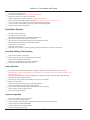
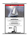
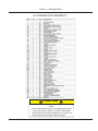
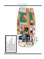
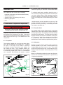
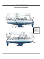
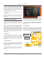
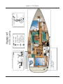
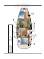
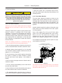
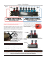
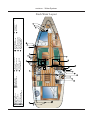
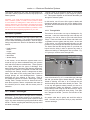
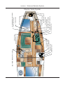
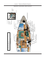
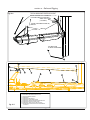
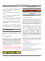
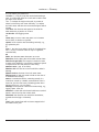
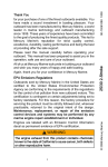
C N A 5.13 F D G E J B A GENERATOR RETURN FUEL LINE 1/4" (.66cm) B GENERATOR FUEL SUPPLY LINE 1/4" (.66cm) C FUEL FILL HOSE 1-1/2" (3.8cm) D FUEL FILL (ON DECK) E FUEL VENT (ON DECK) F FUEL VENT HOSE 5/8" (1.6cm) G FUEL FILTER/WATER SEPARATOR H ENGINE FUEL RETURN LINE 5/16" (.79cm) I ENGINE FUEL SUPPLY LINE 5/16" (.79cm) J ENGINE AND GENERATOR FUEL RETURN PORTS K FUEL CUTOFF VALVES L FUEL LEVEL SENSOR M GENERATOR FUEL PUMP N OPTIONAL HEATER FUEL SUPPLY LINE H M L K I G Hunter 41 • Fuel Systems1 Fuel System Hunter 41 • Fuel Systems ! WARN IN G ! Liquefied propane gas (LPG) is flammable and explosive. Follow these instructions to avoid injury or death from fire or explosion. x This system is designed for use with liquefied petroleum gas (LPG/propane/butane) only. Do not connect compressed natural gas (CNG) to this system. x Keep LPG cylinder and/or solenoid valve(s) closed when the boat is unattended, and when appliances are not in use. x Close cylinder valves immediately in any emergency. x Keep empty cylinders tightly closed. x Close all appliance valves before opening cylinder valve. x Apply ignition source to burner before opening appliance valve. x Test the system for leakage in accordance with the instructions required to be posted in the vicinity of the cylinder each time the supply valve is opened for appliance use. Never use flame to check for leaks! 5.14 5.15 A B C D E F G LPG TANK(s) LOCATED IN STRBD SWIM LOCKER LPG SOLENOID RUBBER GAS LINE HOSE (COPPER IN CERTAIN REGIONS) POWER LINE FROM LPG CONTROL SWITCH GIMBALLED STOVE REMOTE CONTROL SHUT-OFF LOCATED IN GALLEY FACE POWER FROM MAIN ELECTRIC PANEL TO REMOTE SWITCH BOXED AREA DEPICTS ABOVE DECK AREA A B C E F BATTERY CHARGER** SPARE* SPARE* SPARE* SPARE* SPARE* SPARE* G D Hunter 41 • Fuel Systems1 LPG (Liquified Petroleum Gas) Lines Layout Hunter 41 • Fuel Systems This Page Intentionally Left Blank 5.16 Chapter 6 Underwater Gear H41 V1.021507 • P/N 1031381 Hunter 41 • Underwater Gear at a higher than recommended RPM. Your engine manual will specify the maximum recommended RPM. Underwater Gear Your underwater Gear consists of the following: • • • • • To maintain rated power, propellers should be free of nicks, excessive pitting and any distortions that alter them from their original design. Badly damaged propellers should be replaced, but those that are chipped, bent or merely out of shape can be reconditioned by your marine dealer. Propulsion components (sail drive and bow thruster) Steering components Seawater Intake, and discharge skin fittings Monitoring Equipment Keel Consider keeping an extra propeller on your boat. If the propeller becomes damaged, you can replace it with the spare and continue your outing. Check with your dealer if you want to purchase one. 6.1 Mechanical Propulsion Components ! DA NGER ! 6.1.2 Propeller Shaft Keep clear of moving parts at all times. Protect moving parts from access during normal use. The propeller shaft is made of Aquamet 19 or equivalent stainless steel which has excellent corrosion resistance and very high strength. The coupling at one end of the shaft is bolted to the transmission. The other end of the shaft is tapered, threaded, and keyed for installation of the propeller. The propeller shaft passes through the hull encased in the shaft log. Then, on the underside of the hull, is attached a strut, which holds the propeller shaft in position. Propulsion components are any component that would be involved in the movement of your boat. This section will detail the components that are submerged or underwater most of the time. Fig 6.1 will detail most of the components. 6.1.1 Propellers 6.1.3 Alignment The propeller supplied with your boat has been selected as the best propeller for average use. Propellers use “pitch” or the angle of the blades to determine the amount of power exerted from your engines. Do not change the pitch of your propellers without getting your dealers recommendations first. If you change to a different propeller pitch, under no circumstances use a propeller which allows the engine to operate Aligning the engine with the propeller shaft is critical for smooth operation of your boat. Shaft alignment may change slightly after your boat is in use. Your dealer should check alignment as part of commissioning, particularly if there is vibration, a drumming sound, or loss of RPM’s. Below is an illustration showing the steps for alignment, however we recommend this practice be performed by competent professionals. Fig. 6.2 Fig. 6.1 6.2 Hunter 41 • Underwater Gear 6.1.4 Struts 6.2 Steering Components Each propeller shaft is supported by manganese bronze struts fastened to the bottom of the hull. The struts have replaceable bearings to minimize wear and to protect the shaft at the points where it passes through the strut hubs. The strut bearings should be inspected annually and replaced as necessary. Location of the struts can be found in the Underwater Gear Components illustrations at the end of this chapter. ! DA NG ER ! Keep clear of moving steering parts at all times. Protect moving parts from access during normal use! 6.2.1 Steering System WHEEL 6.1.5 Shaft Log / Stuffing Box HANDRAIL COMPASS The shaft log is a fiberglass tube inserted into an opening in the bottom of the boat aft, for the propeller shaft. A short length of flexible hose connects the shaft stuffing box to the shaft log. See fig. 6.1. SHIFT LEVER SHIFT PEDESTAL The stuffing box keeps water from leaking around the shaft into the boat. The stuffing box has a Flex packing system. STEERING PEDESTAL The shaft seal assemblies should be inspected at least annually. RUDDER STOCK DRAGLINK STOP RING TILLER LEVER C PEDESTAL OUTPUT LEVER Figure 6.4 The steering system on your boat uses a rack and pinion setup that connect the wheel to the steering gear via a direct drag link. Fig. 6.4 gives you a view at some of the basic components of this system. 6.1.6 Alignment Aligning the engine with the propeller shaft is critical for smooth operation of your boat. Shaft alignment may change slightly after your boat is in use. Your dealer should check alignment as part of commissioning, particularly if there is vibration, a drumming sound, or loss of RPM’s. To keep it in the top operating condition please read your manual supplied in your owner’s packet. This manual contains all the system requirements and maintenance requirements to keep your steering system working for years. If alignment is necessary, see your authorized service technician. 6.3 Hunter 41 • Underwater Gear 6.2.2 Rudders 6.3 Seawater Intake Your Hunter rudder is constructed with a foam filled composite blade by hand lay-up connected to an internal stainless steel grid and rudder stock structure. The rudder bearings are self lubricating type bearings. Ensure to inspect the free and smooth operation of the rudder stock and bearings at regular intervals. 6.3.1 Skin Fittings and Intakes On the bottom of your boat, you will find skin fittings and intakes for the supply and discharge to your boat’s various systems. Care should be taken that these intakes and skin fittings are cleaned of barnacles and other growth as specified in the maintenance section of this manual to maintain a clear, open passageway. Fig. 6.5 shows you a view at the rudder under your boat. Your steering system is a very important part of your boat and very important to your boating safety. However, all boat operator’s should be prepared for rudder failure or loss. That is why Hunter Marine has a backup rudder Fig. 6.5 system that can be purchased for our current models. Other commercial suppliers offer similar systems at differing benefits and costs. You should conduct your own analysis to determine which alternative is best for you. ! C AU T I O N Fig. 6.6 The optional electronics package you have ordered on your boat will largely determine the underwater gear that is related to the monitoring equipment. Be sure and refer to your documentation in your owner’s packet to find out the details about this equipment. ! Because the backup system can also be lost an operator must be able to sail without a rudder or otherwise be prepared to assemble a makeshift rudder. 6.4 Windlass and Anchoring (Option) 6.4.1 Windlass Important: Look to the Getting Underway Chapter (chapter 12) for information about using your emergency tiller system. The connections and use are detailed in that section. The windlass facilitates the anchoring of your boat by automatically raising and lowering the anchor. To operate the windlass, the windlass power switch at the helm station must be switched on. The next Figure in this section will allow you to observe the cross section illustration of the rudder installed on your boat. This view also shows you the upper and lower rudder bearings. Note: It is important that the windlass clutch is tight for proper operation and safety. Periodically check the clutch and tighten if necessary. 6.4 Hunter 41 • Underwater Gear To tighten the clutch: • Using the emergency handle, unscrew the nut by turning the handle counterclockwise. • With the anchor in the stowed position, tighten the windlass clutch by inserting the emergency handle in the clutch nut. (See fig 6.7) and turn clockwise. Windlass Profile Illustration Emergency Handle • Remove the drum, upper cone, chain wheel, and lower cone. To Operate Manually: Make sure that the safety hook is removed from the anchor chain. Insert the emergency handle into the clutch nut. Clutch Nut • Wash down with water to remove any residue Drum • Turn handle clockwise to retrieve anchor. • Coat surfaces with a light film of lubricant Upper Cone To operate from the bow: • Reassemble the unit and tighten the clutch by turning the handle clockwise. • Switch the power on at the controls • Remove the safety hook Chain Pulley Lower Cone • • Fig. 6.7 • • Note: Refer to your Owner’s / Operator’s Manual in your owner’s kit for detailed information about your windlass. • Lift the protective cap from the foot switch and depress the up or down switch for the desired result. To operate from the helm: • Make sure that the safety hook is removed from the anchor chain 6.4.2 Anchor Your Hunter is equipped with a Danforth type anchor well and drain and a Danforth type anchor as standard equipment. The anchor is selected to suit the size and weight of your boat under normal anchoring conditions, and is most effective in muddy or sandy bottoms. • Turn the windlass switch on • Push the bottom of the windlass control switch (located on the helm) to raise the anchor. Push the top of the switch to lower the anchor. Check out the Getting underway Chapter in this manual, chapter 12 for more information about anchoring your boat. Maintenance: ! DA NGER ! Fig. 6.8 will show you the details of the windlass and anchoring system in illustrated detail, showing the plan view. Make sure that the power is off before performing any maintenance or work on the windlass. • Periodically check the motor and control box electrical connections, remove any residue and cover connections with a small coating of grease. It is recommended that you, once a year, disassemble the windlass and remove residue buildup. To perform this maintenance follow all safety procedures and complete the following: 6.5 Hunter 41 • Underwater Gear NOTE: THE FORWARD "U" BOLT IN THE ANCHORWELL IS CONSIDERED THE STRONG POINT. THAT SHOULD BE USED IF THE VESSEL IS TO BE TOWED NOTE: ALWAYS SECURE ANCHOR RODE TO THE CLEAT OR LASH ANCHOR SECURE TO BOW ROLLER IN ADDITION TO THE QUICK PIN. PLAN (SIZE & SHAPE VARIES BETWEEN MODELS) STAINLESS BOW ROLLER Fig. 6.8 TYPICAL CLEAT LOCATIONS VARY W/MODEL. ANCHOR RODE PLOW ANCHOR tunnel that is build into the hull structure under the waterline. When operated it forces a jet of water from one side of the bow to the other and consequently pushes the bow towards the opposite direction of the jet. You should familiarize yourself with the maneuvering and operation of the bow thruster in open and still water before attempting to maneuver in tight spaces or marinas! The bow thruster is powered by your on board DC system and it is vital for this to be at full charge and capacity to assure full functionality. Please refer to the supplied vendor specific manual for safety tips and service requirements. (CHAIN OR ROPE OR COMBO) DANFORTH ANCHOR STAINLESS BOW ROLLER WELL: SMALLER MODELS WELL: LARGER MODELS ! DA NG ER ! ELEVATION DANGER OF SERIOUS INJURY: ROTATING PROPELLER – DO NOT SWIM IN THE VICINITY OF THE BOW THRUSTER! WATERLINE Fig. 6.9 Fig 6.9 shows you a profile view of the anchoring, and windlass system. This illustration shows the smaller and the larger anchor well, in relation to the location. ! WA R N I N G ! Anchoring in unusual water, and or weather conditions will require additional precautions. Consult an approved guide for suggestions. 6.5 Bow Thruster (Option) Fig. 6.10 Your Hunter boat is offered with a bow thruster option. If installed the bow thruster will assist maneuvering in tight spaces or marinas and with adverse wind directions. The bow thruster is installed below your v-berth bunk into a 6.6 Hunter 41 • Underwater Gear Bow Thruster Controls Located at the helm. Left button move the bow port, the right button moves the bow starboard. 6.7 Troubleshooting Though we cannot cover every problem you encounter in boating, we hope to assist you basic operation and maintenance of the ponents aboard, or installed on your might in the comboat. As difficult as it would be to also cover every option or component installed we hope we have covered the basic essentials you will need in order to have many a safe and comfortable outings in your new boat. As in all cases always consult your OEM manuals in all cases of review of the documentation of the components aboard or installed on your boat. If the manuals are not available in your owner’s packet, contact Hunter Marine, or your dealer. It is the ultimate in importance that you understand all you should about the equipment on your boat. Here we give you a short guide concerning the troubleshooting of the equipment that fall in the underwater gear section of your boat. Read this guide, and use it in trying to discover the root of any issues that might arise. Remember: OEM manuals take precedence over any information you may find in the Hunter Owner’s or Operator’s Manuals. 6.7 Hunter 41 • Underwater Gear Thru Hulls Port and Starboard 2 1 3 12 7 13 10 1. ANCHORWELL DRAIN (X2) 2. WATER TANK VENT (X2) 3. WATER HEATER DISCHARGE 4. BILGE PUMP DISCHARGE 5. WASTE TANK VENT 6. AFT SUMP PUMP DISCHARGE 7. FWD SUMP PUMP DISCHARGE 8. ENGINE EXHAUST 9. LPG LOCKER DRAIN 10. OPT. WATER MAKER DISCHARGE 11. OPTIONAL AC AFT DISCHARGE 12. OPT. GENERATOR DISCHARGE 13. OPTIONAL AC FWD DISCHARGE 11 8 9 4 6 2 5 1 6.8 Hunter 41 • Underwater Gear Troubleshooting Problem Excessive vibration Poor performance Possible Cause Resolution Material obstructing propeller Remove material from propeller, shaft, or rudder by revering engines. If necessary, stop engines and cut or pull material away. Bent prop or shaft Replace propeller. If vibration continues, see your dealer for service. Excessive play in shaft log Check shaft log for wear. Avoid sudden torque changes. See your dealer for repairs. Bent rudder Replace. See your dealer for service. Material wrapped around propeller Run engines in reverse. If necessary, stop engines and cut or pull material away. Damaged propeller. Wrong propeller Replace propeller in use. 6.9 Hunter 41 • Underwater Gear Notes: 6.10 1. ENGINE PICK UP 2. AFT VANITY DISCHARGE 3. GALLEY DRAIN 4. KNOT TRANSDUCER 5. DEPTH TRANSDUCER 6. FWD VANITY DISCHARGE 7. MACERATOR DISCHARGE 8. OPTIONAL AFT HEAD PICK UP 9. OPTIONAL GENERATOR PICK UP 10. OPTIONAL AC PICK UP 11. OPTIONAL OVERBOARD AFT DISCHARGE 12. OPTIONAL FWD HEAD PICK UP 13. OPTIONAL OVERBOARD FWD DISCHARGE 9 1 10 8 2 3 Bottom Thru Hulls Hunter 41 11 5 4 12 6 13 7 Hunter 41 • Underwater Gear 6.11 Hunter 41 • Underwater Gear This Page Intentionally Left Blank 6.12 Chapter 7 DC Electric Systems H41 V1.021507 • P/N 1031381 Hunter 41 • DC Electric DC Electric Systems 7.1 The DC Electrical System This section will provide you with the information necessary to understand and operate your DC Electrical Systems. The DC System consists of the following systems or components: It is not the scope of this manual to educate you on repair, or extending the electrical system. We cannot educate you in the principals of basic electricity. The scope of your manual is to provide you with the basic information you will need for safety, operation, and maintenance of these systems. • • • • • • • • • • • • • • • • • • • There are two main categories, the DC Electrical system and the AC Electrical systems. These are two entirely different systems though in lots of areas one dependant on the other. From that point we will subdivide the main categories into sections beginning with the source of the power and continuing throughout the system to the component based in the systems circuitry. Remember within each main system are many sub-systems or circuits. These will be outlined as best as we can from beginning to end. ! WA R N I N G ! Batteries Battery Switches Main Panel Lighting Pumps Distribution Panel Oil Changer (Option) Shower Sump Windlass Generator Starter Engine Starters Head Components Refrigerator / Freezer Fresh Water Pump Macerator CO Monitors Ventilation Entertainment Centers Fire Extinguishing System Throughout this section, the components will be separated into categories of Power Supply and related components such as switches, breakers, fuses, panels, chargers, grounding, the components that are powered by the DC electrical system, and finally operations and suggestions for control or usage of the systems or components. At the end of the section, you will find a “Legends” section that will detail the switch, breaker, and control panels aboard your boat. Do not rely on the information in this manual as a repair guide, as always only competent electrical service personnel should attempt to repair any electrical equipment or extension of the electrical systems. To do so would risk electrical shock, or damage to the boats systems or components. 1 Shore Power 2 Shore Power 3 House Batteries 4 Optional Inverter 5 Optional Generator 6 Optional Battery Charger 4 GENSET RESET 6 5 ISOLATION TRANSFORMER NOTE: Be sure the battery selector switch on the battery charger is in the proper position for your battery type. BATTERY SWITCH PANEL SHORE POWER RESET 3 1 MAIN PANEL ** 2 Fig. 7.1 7.2 Hunter 41 • DC Electric 7.1.1 Batteries ! WARN IN G ! ! DA NGER ! Batteries contain a large amount of potential electrical energy! Extreme care must taken when working with batteries. An improper connection to a battery can release enough energy to cause severe personal injury or fire. Batteries contain Sulfuric Acid and can cause severe personal injury if mishandled. Avoid contact with eyes, skin, or clothing. In case of contact, flush with water at least 15 minutes. If swallowed, drink large quantities of water or Milk of Magnesia, beaten egg, or vegetable oil and get medical attention immediately. The following precautions must be taken: ! WARNING ! • The wiring to the batteries must have proper over current protection in the form of fuse or breakers. Charging batteries produces gasses which can explode if ignited. Explosion can shatter a battery. Battery acid can cause severe personal injury such as blindness. Keep flame, spark, and smoking materials away from batteries while charging. Charge in a well ventilated area. • Use only battery chargers that have been listed by a testing agency, such as Underwriters Laboratories, Inc. • Follow the wiring diagrams exactly. To remove the battery: The DC System derives its power from two separate battery banks. 1. Turn off all power drawing breakers and isolate battery. A circuit breaker on the battery switch panel connects the battery to the electrical system. The batteries supply power, first to the battery selector switch then to the DC side of the main control panel, and finally through the distribution panel. From these panels, power is distributed to such equipment as cabin lights, instruments, and accessories. 2. Remove negative (-) cable first, then the positive (+). When you install a battery, the battery connections must be made properly. 1. Attach the positive cable to the positive (+) terminal on the battery. The negative terminal of all banks are attached to the DC Ground connection on the engine. This system, known as the negative ground system, is the approved system for marine DC electrical systems. The battery wiring system has two color coded wires. The yellow wire is the ground (negative), and the red wire is (positive). 2. Attach the negative cable to the negative (-) terminal on the battery. Note: Batteries should always be removed and installed by trained, qualified persons to avoid all damages. 7.1.2 Battery Switch To avoid explosions, do not use jumper cables and a booster battery to start the engine. If batteries are dead, then remove and recharge them ashore. Each battery bank has a battery selector switch (Fig. 7.2) located under the chart table. The selector switches are marked as to which battery they control. Turning the selector switch to the Off position turns power off to the respective circuits, likewise, the On position turns power on. Batteries produce hydrogen and oxygen gasses when they are being charged. These explosive gasses escape through the vent/fill caps and may form an explosive atmosphere around the battery if ventilation is poor. This gas may remain around the battery for several hours after charging. Sparks or flame can ignite the gas and cause an explosion. 7.3 Hunter 41 • DC Electric tery selector switch panel. Systems that would normally require you to energize them for use are provided with switches. The breaker and switch panels are detailed further in the end of this section under “Legends.” 7.1.7 Generator (Option) Although, technically, the generator is part of the AC System, because it supplies AC power, the starting of the generator requires DC power. The generator starting receives power from the start battery bank. The generator supplies 120 volt 60 hz AC power for operating devices and equipment controlled through the AC control panel (Main Distribution Panel, MDP). Fig.7.2 When the generator indicating light is on and the generator breakers are on, AC power is supplied to AC control panel devices and equipment. The battery switch panel houses the breakers for some of the main components in your DC system. The breaker controls are marked at the switch panel, and control systems or components on your boat that require a connection that remains energized even through the Main Panel may be de-energized. Refer to the “Operation and Procedures” part of the AC Electric section for information on starting the generator. You can find or locate the generator and all the respective components using the Generator System Drawing at the end of this chapter. The breakers and switches are described in greater detail in the “Breakers and Switches” section of this chapter. 7.1.3 Battery Charging System 7.1.8 Main Control Panel (DC Side) Refer to the power supply locator drawing (Fig. 7.1) at the beginning of this section for the location of the battery charger. The charger is protected by a fuse on the positive and ground side at the charger. To operate the charger, ensure that it is operating: 1. Connect the shore power cord to the shore power inlet on the stern of the boat on the stbd. side. Then to the dockside supply. 2. Turn on the AC Main breaker, located in the aft cabin. 3. Turn on the Battery Charger switch on the control panel. 7.1.5 Breakers, Switches, and Fuses All electrical systems aboard your boat are provided with over-current protection in the form of breakers or fuses. Examples of breakers are the system or component controls at the Main Distribution Panel, or MDP, or in the bat- 7.4 Hunter 41 • DC Electric You can view the parts of the DC side of the main control panel here (Fig. 7.3). Notice the battery selector switch at the top left, when switched on the respective voltage of the battery is shown on the right by the digital volt meter. Indicator lights are built into most switches and alert you that the selected system is powered. The distribution panel is outlined in the legends section of this chapter. Refer to the “Operations” section of this chapter to view instructions on how to energize the separate systems on your boat. Fig.7.4 The power switch turns the monitor on, then select the tank you want to monitor. The gauge on the left will show the amount remaining in the tank. 7.2 Systems and Components There are many systems and components on the DC side of your boat from emergency and safety to entertainment. These systems make up the largest part of your electrical system. The waste tanks are also monitored from this location by selecting numbers six, or seven from selector switch #1 on Fig. 7.4. Here we will discuss the electrical parts of those systems and try and give you a better understanding of the uses and features of your DC electrical systems and components. Since the largest part of your controls are at the MDP, we will start there and run down the systems and components as they are listed on the MDP. From there, we will look at the battery switch panel, and finally, the helm controls. 7.2.3 Refrigerators The breaker marked “refrigerator”, on the main breaker panel behind the nav station acess panel, supplies power to the DC powered refrigerator aboard your boat. See Fig. 7.5 for the arrangement layout of this system. 7.2.1 DC Main A REFRIGERATOR/FREEZER UNIT W/BUILT IN COMPRESSOR B POWER RUN TO D.C. PANEL In order to energize the DC system aboard your boat, you must turn the breaker marked “DC Main”, on the battery switch panel, to the “On” position. This supplies power to the remaining breakers and systems on the distribution panel. A NOTE: CONSULT PRODUCT MANUAL FOR OPERATING THE REFRIGERATOR AND FREEZER UNITS. B 7.2.2 Water Systems The water systems are outlined in the Water Systems chapter in this manual. However, the controls and monitors for these systems are all powered by the DC Electrical system. AREA DEPICTED ABOVE ER R** SP PAR RE* AR The water tank monitor as shown in Fig. 7.4 allows you to select the tank to monitor the water level in the respective tank. SP PAR RE* Fig.7.5 7.5 Hunter 41 • DC Electric 7.2.4 Lighting Systems 7.2.6 Entertainment Centers There are basically four different lighting systems aboard your boat. These are the interior and exterior lighting, the safety and navigational lighting, and, if supplied, the courtesy lighting. The entertainment centers in the berthing areas of your boat are 12 volt DC powered. The power is supplied through the distribution panel. The television is AC powered from a DC to AC inverter, and the stereo is DC powered. More information about the controls of your entertainment centers and equipment can be found in your owner’s packet. The interior and exterior lighting systems are separated because of the method in which power is supplied to the two systems. The interior lights are powered from the MDP and marked Cabin Lights. The exterior lighting is powered from the MDP and have switches on the main control panel for their operation. 7.2.7 Oil Changer (Option) Your boat may be equipped with the optional oil changer. The oil changer receives its power from the DC Electrical System. The breaker is located on the Battery Switch Panel. The breaker is marked “OIL CHANGER.” The engine room and Lazarette (generator) area lighting are also powered from the MDP. The next area, safety and navigational lighting, closely follows Coast Guard regulations regarding safety and navigational lights. They are as follows: • • • • Consult your mechanical arrangement for the location of the oil changer. Nav Lights Steaming Light Mast Light Deck Light The red and green lights on the bow rail and the white facing light on the transom are known as “Nav Lights”. These lights should always be on when motoring. The “steaming” light is the forward facing light mounted halfway up the mast. This should be on when underway with sail power only. The anchor light is a 360 ° light mounted at the top of the mast and should only be on when anchored. Note: Discharge of oil is prohibited. The Federal Water Pollution Control Act prohibits the discharge of oil or oily waste into or upon navigable waters and contiguous zone of the United States. If such discharge causes a film or sheen upon, or discoloration of the surface of the water, or causes a sludge or emulsion beneath the surface of the water, violators are subject to a penalty of $5,000. The engine area lighting is controlled by the courtesy light breaker, and the Deck light gives lighting to the foredeck area. Lighting circuits and locations are outlined in the end of this chapter. 7.2.10 Bilge Pump Systems Your boat is equipped with 2 bilge pumps and one emergency bilge pump. For locations of the bilge pump systems, consult your Mechanical Arrangement Drawing or the Sanitary Systems Drawing. 7.2.5 CO Monitors In each area aboard your boat, you will find a CO Monitor (Carbon Monoxide Monitor). We care about your safety and have installed these CO Monitors to show our concern. For more information about the CO Monitors mounted on your boat, consult your owner’s packet and find the documentation for the CO Monitors. The Bilge Pump System consists of a pump and a float switch. When the water level rises far enough to activate the float switch, this activates the pump which lowers the water level down to a point that the float switch stops the 7.6 Hunter 41 • DC Electric 7.2.12 Fire Extinguishing Systems power. Fig. 7.10 shows you the typical wiring. For more information about your bilge pump system, see Sanitary Systems. In the engine room, there is a fire extinguishing bottle installed. This system is DC powered with the relay, or “module”, and the alarm at the helm station. When a fire is detected on your boat, the alarm will sound and set off the Halon bottle. This relay will shut down the engines, the blowers, and the generator. To reset the system, activate the reset switch on the monitor at the helm. See Fig. 7.9. 7.2.11 Ventilation Fire Alarm Fi Al Ventilation is a very important issue with your boat, with the potential for Carbon Monoxide buildup (See Boating Safety Section), along with the simple comfort of fresh air or air conditioning, ventilation is a standard that is a necessity. High Hi h Water W t Alarm Al 7.2.13 Shower Sump The shower sump is part of the Sanitary System and more information about the Shower Sump can be found in that section. However, the breaker control for the Shower Sump can be found on the MDP. On your boat, there are essentially three types of ventilation, the air conditioning system (AC system), the blower, and the Bomar hatches, which supply you with fresh air when opened. Since the air conditioning system is AC powered (see AC Electric Section) and the hatches require no power, we will detail the blower (or fans), and their function, here. 7.2.14 Windlass Your boat may be equipped with an optional windlass. It receives its power from the DC electrical system. The windlass offers you the ability to raise and lower your anchor. There is also a circuit breaker at the battery switch. The windlass can be operated from the bow. See manufacturer’s owner’s manual about the proper and safe operating procedures. See Fig. 7.12. For blower location, consult your Mechanical Arrangement illustration in the Boating Safety Section, or the Ventilation illustration in the same section. ! WARNING ! Fuel fumes in the engine compartment can explode. Before working on electrical wiring, ventilate engine room and disconnect battery cables to prevent sparks. The engine room blower is an exhaust fan which will remove any exhaust fumes from the engine room, as well as, removing heated air. 7.7 Hunter 41 • DC Electric 4. Turn the macerator switch to the “on” position at the Nav Station. This is a momentary switch, you must hold the switch to operate. 7.3 Operations and Maintenance 7.3.1 To operate the 12 Volt DC System: 5. Allow the macerator to run until the holding tank is empty, but no longer. Running the macerator when the tank is empty will damage the pump. When full, the macerator will have a low pitch grind. When empty, this changes to a high pitch grind. 1. Switch the main battery switch in the main salon bunk 2. Switch the DC main circuit breaker at battery switch panel to ON. 3. Switch on relevant breakers at the MDP. 6. When you hear the pump speed up (indicates tank is empty), immediately switch the MACERATOR breaker to OFF. Note: Always switch circuit breakers off when you leave your boat unattended. 7. Close the seacock. 7.3.2 To manually operate your bilge pumps: ! WARN IN G ! Note: The power to the MDP does not need to be energized in order to manually operate your bilge pumps, however for automatic operation power does need to be supplied to the MDP. If the seacock is not closed, the holding tank will fill with sea water and could possibly flood the boat. 1. Locate the bilge pump switches at the Nav station and switch them to the manual position. 7.3.4 To operate the engine compartment blower: Power up the DC system as discussed in this section. Turn on the rocker switch located in the aft cabin. 2. Another procedure to be used in extreme circumstances involves locating the float switch and manually rotating the float handle on the side of the float switch to simulate the float switch being underwater. This will energize the pump and the pump will operate. 7.3.5 To operate the windlass: 1. Power up the windlass from the battery switch. 2. The controls for the windlass are on the deck to the right of the anchor well. 7.3.3 To operate the macerator pump: ! C AU T I O N ! For more information about your windlass, refer to the Underway Section of this manual. Do not place facial tissue, paper towels, or sanitary napkins in head. Such materials can damage waste disposal systems and the environment. 7.3.6 CO Monitors For your protection, we have installed CO monitors aboard your boat. Be sure and check your Owner’s Packet for more info concerning your CO detectors. You can also review that dangers of CO in the Boating Safety Chapter of this manual. Important: U.S.Coast Guard regulations require that boats have a sanitation system on board to control pollution. Waste is to be stored in a holding tank or other device so it can be properly disposed of at a shore facility. Discharging this waste overboard in the U.S. lakes, rivers, bays, and sounds and within 3 miles of shore in international waters is prohibited. Check with the Coast Guard regarding regulations in your area. Do not spray waxes or cleaning agents on the monitor. 1. Power up the DC panel as described in this section. 7.3.7 Maintenance 2. Open the seacock valve located under the steps to salon. The maintenance of your DC system is ensuring that all connections are clean, tight, and covered with a corrosion inhibitor compound. 3. Switch the MACERATOR breaker at the DC main electrical control panel to ON. 7.8 Hunter 41 • DC Electric Problem Troubleshooting Cause Solution 12 volt equipment not working Battery selector switch turned off Check battery selector switches and ensure they are on Battery not charging with engine running Check alternator, belt, etc. Change alternator, tighten belt Battery not holding a charge Faulty Battery Faulty battery charger Replace battery Have your dealer check battery charger 12 volt DC device not working Circuit breaker for device is off Weak or dead battery Switch breaker to on Change battery selector switch position, recharge battery Check 12 volt DC connections, tighten or repair as needed Faulty electrical connection Cabin lights not working (off or dim) Blower inoperative Cabin breaker for device is off Weak or dead battery Light bulb burned out Switch breaker to on Change battery selector switch position, recharge battery Replace bulb Tripped breaker Weak or dead battery Switch breaker on Recharge or replace battery 7.9 Hunter 41 • DC Electric Notes: 7.10 UE BL NEGATIVE BUS BAR W OFF BLUE 7.11 TO ARCH LIGHT (PROVIDED WITH COCKPIT STEREO OPTION) JUNCTION BOX A B YELLOW NEGATIVE TO NEGATIVE BUS BAR (SEE EX.) EACH CIRCUIT IN PARALLEL, BLUE (LOAD TO BREAKER) AND YE A O PANEL BRKR. BL UE CABIN LIGHTS 1 LL FROM BATT. YELLOW FROM BATT. OW EXAMPLE SWITCH PANEL WIRING (PARALLEL CIRCUITS) LL YE C C BATTERY CHARGER** C SPARE* SPARE* SPARE* SPARE* SPARE* SPARE* B LIGHT SWITCH COURTESY LIGHTS MAP LIGHT FLUORESCENTS RECESSED LIGHTS DOME LIGHTS SWIVEL LIGHTS C 12 VDC Lighting Hunter 41 BLUE/WHITE YELLOW LIGHT POS./NEG.LEADS TO LIGHT TO NEXT LIGHT EXAMPLE LIGHT WIRING (PARALLEL CIRCUIT) Hunter 41 • DC Electric Hunter 41 • DC Electric Notes: 7.12 7.13 STERN LIGHT STERN LIGHT COMPASS LIGHT INSTALLED ONLY WHEN ARCH IS WIRED FOR SPEAKERS ARCH LIGHT COMPASS LIGHT ARCH LIGHT ALL LINES LEAD TO D.C. SIDE OF MAIN PANEL ** STEAMING LIGHT ANCHOR LIGHT TOP OF MAST STEAMING LIGHT BOWLIGHT BOWLIGHT COMMON GROUND FOR ANCHOR/STMING LIGHT POSITIVE POWER FEEDS ALL LINES RUN THROUGH HULL EXCEPT MAST LIGHTS RUN THROUGH HEADLINER ANCHOR LIGHT TERMINAL STRIP FOR MAST LIGHT LEADS LOCATED INSIDE CABIN AT COMPRESSION POST 12 VDC Deck LIghting Hunter 41 • DC Electric Hunter 41 • DC Electric Notes: 7.14 Chapter 8 AC Electric Systems H41 V1.021507 • P/N 1031381 Hunter 41 • AC Electric Systems The AC System consists of the following systems or components: • • • • • • • 8.1 Power Supply Components As we mentioned, the two main sources for AC power are the shore power and the generator. There is a rocker switch on the control panel that allows you to switch between the two power sources without energizing both at once. Shore Power Connection Shore Power Breaker Isolation Transformer Generator (Optional) MDP Breakers Components The AC power supplied in the boat is provided by a main breaker located in the aft cabin starbaord side. The branch breakers are in the MDP located at the nav station. Important: The AC system is connected to the living quarters of your boat through an AC junction panel located on the Port side behind the cabinets in the Salon area. See the AC Mechanical Arrangement for further location details. ! DA NG ER ! ! WA R N I N G ! Never work on an energized circuit! Always treat any circuit as if it were live! Always have trained, competent technicians to service your electrical systems! specialized test equipment. Never think you know whether a circuit is “live”. Always have qualified, competent professionals inspect or make repairs to your electrical systems. 8.1.1 Shore Power Supply Your boat has a shore power inlet a 30 amp 120 volt (220 overseas) line supplies power to the AC MDP. Throughout this section, the components will be separated into categories of Power Supply and related components such as switches, breakers, fuses, panels, chargers, grounding and bonding, the components that are powered by the AC electrical system, and finally, operations and suggestions for control or usage of the systems or components. At the end of the section, you will find a “Legends” section that will detail the switch, breaker, and control panels aboard your boat. ! WARN IN G ! Using a damaged or improper cord for shore power can cause electrical shock and serious injury. Use a cord specifically designed for shore power connection. Do not use a household extension cord. The sources for power supply in your AC electric system are the shore power, the generator, and AC electric supplied through the inverter. We will explain both systems as if your boat came to you with a generator installed. If you opted not to have the generator, then simply omit the sections that deal with that part of the boat. They will not apply to your boat. ! CAU TIO N ! Water is an excellent conductor of electricity. Keep shore power cord out of water. Do not operate any AC device while you or the cord are in the water. To prevent injury or equipment damage, keep all AC system components dry. Note: It is important that you review the “Electric Shock” pamphlet included with your manual and understand the importance of electrical safety. While electricity is one of our greatest friends, it can well be your worst enemy. Be sure and follow the warnings posted in this manual and your component or systems manuals in your owner’s packet and practice good safety. Always have trained, competent technicians to service your electrical systems, it could mean your life. ! WARN IN G ! DO NOT connect the shore power cord to the dockside electrical source first. You could accidentally drop the cord into the water, which may result in electrical shock and serious personal injury. 8.2 Hunter 41 • AC Electric Systems ! C AU T I O N 8.1.4 Distribution Panel (MDP) ! The distribution panels for both AC and DC power are located behind the nav station seat. Be certain the water heater is full of water and does not contain air. If the water heater is not full of water, damage to the heating elements may result when the electrical power is turned on to the unit. Fig. 8.1 gives you a look at the shore power connection on the transom of your boat. Fig. 8.2 Fig. 8.1 8.1.5 Generator (Option) Later on in this section, we will detail the steps to connecting your shore power. Lets take a look at more of the shore power components. If you opted to have the generator installed, then you have made a good choice. We supply you with the best all around generator setup for your needs aboard this boat. However, the generator is a diesel powered engine, so there are some safety rules for any type of fuel engine. Lets look at some of those, then we will discuss more about the function and operation of the generator system. 8.1.2 Shore Power Cord We have supplied you with a durable 50’ shore power cord. The cord will have a male connection on one end and a female connection on the other end. Do not use chemicals to clean or service your shore power cord, unless specified by the manufacturer. Follow the manufacturer’s recommendations on servicing or cleaning your shore power cord. ! DA NGER ! Fuel leaking from any part of the fuel system can lead to fire and explosion that can cause serious bodily injury or death. Inspect system before starting engines. 8.1.3 Isolation Transformer Beyond the shore power connection and the shore power breaker, your AC power will be routed through the Isolation Transformer. See the Mechanical Arrangement Illustration for the location of the ISO Transformer. ! DA NG ER ! Never enter the engine compartment without proper ventilation first. A spark caused by power tools or lighting equipment could result in fire or explosion which could cause personal injury or death. The ISO Transformer is a standard “dry” type 3.6 KVA transformer that basically isolates your boat from the shore power. It is a valuable safety feature aboard your boat. 8.3 Hunter 41 • AC Electric Systems Though the outlets are a system or a component such as in the next subject, we have placed the descriptions in the Power Supply subject due to the purpose of their installation. ! DA NGER ! As with any fuel burning engine, Carbon Monoxide is a concern. Read the Boating Safety section of this manual, and educate yourself about Carbon Monoxide poisoning. It could mean the difference in your life and the life of your loved ones. As with the DC System, there are several AC powered systems or components aboard your boat. Here we will break those down for you with a function and description of each one. Later in the Operations and Maintenance section, we will describe the use or operation of these systems or components. The generator is comprised of a fuel supply, return, and an exhaust system. The fuel supply is comprised of a supply valve, supply hose, and a fuel filter, along with the return hose, and electric fuel pump. 8.2 Systems and Components. The exhaust system is made up of an exhaust hose, a muffler, and the exhaust outlet. See your Mechanical Arrangement Illustrations for locations of these components. They can be found at the end of each pertinent section, or at the end of this section. The entire AC system will be laid out in an illustration showing locations for each of the components. 8.2.1 Battery Charger The battery charger (Fig. 7.3) can be located by reviewing your power supply components illustration in the beginning of the DC Electric section. The charger is protected by a fuse on the positive and ground side at the charger (Fig. 7.3). The fuel supply components will be described in greater detail in the Fuel Section and the exhaust will be described in the Waste and Sanitary Section of this manual. 8.1.7 Breakers, Switches, and Fuses All electrical systems aboard your boat are provided with over-current protection in the form of breakers or fuses. Examples of breakers are the system or component controls at the Main Distribution Panel, or MDP Systems that would normally require you to energize them for use and are provided with switches. Fig 8.3 The breaker and switch panels are detailed further in the end of this section under “Legends.” The circuit breakers for the battery chargers are located on the Main Distribution Panel (MDP). 8.1.9 Outlets and GFI Components 8.2.2 Water Heater The outlets aboard your boat are for AC electrical connections to supply power to your AC accessories. They are just like your outlets in your home and supply 110 volt (220 volt overseas) AC power. ! CAU TIO N ! Be certain the water heater is full of water and does not contain air. If the water heater is not full of water, damage to the heating elements may result when electrical power is turned on to the unit. There are 2 required GFI outlets aboard your boat. One is in the galley, one at the Nav station. Though there are several other outlets, they are wired in the circuit of an existing GFI. The other outlet such as the one that supplies power to your microwave receives power from the MDP and breaker protected at that point. These are usually placed behind cabinets or the components that they supply power to and aren’t visible. The water heater use and function is described in the Water Systems Section. Here we will detail the electrical side of the heater. The water heater is powered by the AC MDP. It is much 8.4 Hunter 41 • AC Electric Systems the same as an electric water heater in your home except in this case, the heater uses 120 volt (220 overseas), but it uses elements to heat the water to a specified temperature. Consult the manufacturer’s documentation for any internal information about the water heater. 8.3.2 Shore Power First the Shore Power System is a convenient way to obtain power should you be docked. Be sure to read the warnings posted earlier in this section on shore power safety. 8.2.3 Microwave The microwave is powered with the 120 volt (220 overseas) power through the breaker marked “Microwave.” There is a 120 volt (220 overseas) receptacle behind the microwave that it is plugged into. This outlet is not part of the GFI circuit. It is protected by the breaker on the MDP. 1. Turn off shore power / generator selector on the control panel. 2. Shut down the generator if it is in operation. 3. Connect the female end of the shore power cord to your boat’s shore power inlet receptacle. Be certain that the lock ring is tightly secure. If there is a cord already supplied at the dock be sure to unhook the cord from the dockside outlet. 8.2.6 Air Conditioning The Air Conditioning system is 120 volt (220 overseas) AC powered and powered from the AC MDP. The cooling water pump is controlled by a relay at the compressor and is energized when the Air Conditioning Compressor comes on. 4. Connect the shore power cable to the power supply. When connecting the shore power cable to the dockside outlet, be sure to make certain that the cable has sufficient slack to prevent stretching during tidal changes. You can consult the Arrangement Illustration at the end of this section for location information, or see the Mechanical Arrangement in the Boating Safety Section. The Water Systems will show you the Pick-up and Strainer for this system. 5. Turn on main breaker located on MDP. If there is no power to the electrical distribution panel (MDP), check the following: It is very important for you to read and understand the operation and the maintenance for the systems or components in your AC Electric System. This will save failure of components or systems, as well as, make your boat a safer, more enjoyable investment. * Breaker switch at dockside power. Always make certain that the pick-up and discharge valves for the Air Conditioning System are opened before using. Failure to do so will cause permanent damage to your compressor. Also, be certain that the strainer is clean. See the Water Systems section for details on cleaning the Strainers. 1. Turn off AC main breaker on the MDP. * Main breaker switch located in the aft cabin. 8.3.3 To Disconnect the Shore Power: 2. Turn off the dockside breaker. 3. Disconnect the shore power cord from the dockside outlet. 4. Disconnect the shore power cord from the boat’s shore power connection. 8.3 Operations and Maintenance 5. Store your cord in a safe, dry location. 8.3.1 To Operate the AC Electrical System 8.3.4 To Start the Generator (Option) If you opted for the generator system, then you will, as we have mentioned, have the capabilities for two separate AC Electric systems. We will discuss the procedures for energizing both. 1. Shut down all AC devices and equipment. 2. Disconnect shore power if connected. Set AC MAIN 8.5 Hunter 41 • AC Electric Systems circuit breaker to OFF. 8. Consult your Generator OEM manual for proper start up procedures. 3. Start generator. (See generator start-up instructions following). 9. Check for water coming from the exhaust outlet pipe. Water flowing from the pipe indicates the water is circulating through the generator cooling system. You should see water flowing shortly after generator starts. 4. Select GENERATOR breaker on the MDP. 5. Switch on only the circuits you will be using. 8.3.5 Generator Start-up 10. Inspect the exhaust system for leaks. If you detect leaks or smell fumes, shut down the generator immediately. Do not restart the generator until you have corrected the problem. ! DA NGER ! Carbon Monoxide can be harmful or fatal if inhaled. Inspect generator exhaust system for leaks at each generator startup. 11. Allow the generator to warm up before connecting a heavy electrical load. Keep the load within the nameplate rating. Note: Infrequent use of the generator may result in hard starting. For detailed start-up information, refer to the generator operating manual. 1. To gain access to the generator, remove nav seat. Check generator for signs of fuel or oil leaks. If your boat has diesel engines, check the fuel filter. 8.3.6 Generator Shutdown 2. Check area for fuel fumes. If you detect fuel fumes: 1. Shut off all AC devices and equipment, and the shore power / generator selector switch. a. Evacuate the boat immediately b. Notify the dock, fire department, or Coast Guard of the condition. 2. Allow generator to run for one to two minutes at no load to allow the engine to cool down. c. Open all hatches, doors, and ports for natural ventilation. 3. Press GENERATOR Start/Stop switch to STOP. 4. Close fuel valve and seacock. d. When you can no longer smell fumes, locate the source. Using a hand held pump, carefully remove any fuel from the bilge. Dispose of this fuel in a safe, approved location. 8.3.7 The Air Conditioning System 1. Ensure you have 120 volt (220 overseas) power to the MDP. 3. If you do not smell fuel fumes, make sure fuel shutoff valve on fuel line to generator is open. 2. Check to make sure that the seawater intake, and discharge for the A/C system cooling is open and that the strainer is clean and debris free. 4. Check generator oil level. Refer to the generator manual for instructions. Add oil if necessary. 3. Energize the Air Conditioning system at the MDP panel. 5. Check generator coolant level. See generator manual for instructions. 4. Check to make sure that the discharge is flowing at the Air Conditioning cooling water discharge. 6. Open generator seacock. Valve is open when the handle is in line with hose. Seacock is located forward of the generator sea strainer. 7. At MDP, make sure source breaker is in the off position. 8.6 Hunter 41 • AC Electric Systems Troubleshooting g Problem Possible Cause Solution No AC power Main breaker(s) aft cabin Turn breaker on or reset tripped or off Shore power cord not con- Check cord, plug in if necessary nected Loose or disconnected wire Tighten connections. See your dealer No power to AC devices Breaker(s) at AC control Center tripped or off Shore power cord not connected Loose or disconnected wire Turn breaker on or reset Check cord. Plug in if necessary Check cord. Plug in if necessary Electrical demand greater than generator output Switch off devices and equipment not needed Switch PARALLEL breaker off to reduce demand Use shore power AC line if available Inadequate power to AC devices (generator running) Tighten connections. See your dealer Continuous tripping of main Cause of problem not corbreaker rected Determine cause and correct problem before resetting breaker See your dealer if problem persists Generator will not start Battery discharged or dead Recharge or replace battery No power at AC outlets Outlet breaker in AC control center OFF Ground fault interrupter tripped Switch breaker to ON Reset button on outlet and test 8.7 Hunter 41 • AC Electric Systems 8.8 10 1. SHORE POWER INLET 2. 120 VAC OUTLETS 3. 12 VDC OUTLETS 4. GFCI OUTLETS 9 1 2 5. AC PANEL 6. DC PANEL 7. WATER HEATER 8. MICROWAVE 3 2 8 4 2 3 ** 5 4 6 9. SHORE RESET BREAKER 10. TRANSFORMER 4 2 2 7 3 2 Hunter 41 • AC Electric Systems AC Electric Wire Run Layout 8.9 Hunter 41 • AC Electric Systems This Page Intentionally Left Blank 8.10 Chapter 9 Water Systems H41 V1.021507 • P/N 1031381 Hunter 41 • Water Systems The fresh and raw water systems consist of the following components: • • • • • • • • • • spigot. 3.Open the cold water faucet closest to the potable water inlet on the boat. Dockside Water Supply Fresh Water Tanks and Fills Fresh Water Pump A/C Cooling Pump Raw Water Pick-up and Strainer A/C Pick-up and Strainer Generator Cooling Pick-up and Strainer Engine Seacocks and Strainers Fixtures and Valves Water Heater 4. Open the potable water supply spigot. As soon as a steady stream of water comes out of the faucet on the boat. Close the spigot. 5. Check the boat’s water system for leaks. This inspection is particularly important when you use the potable water hookup the first time. The fresh water system is now ready for use. 9.1 Dockside Water Supply 9.2 Water Tanks (on board water supply) When you are docked, you can connect a pressurized dock water supply to your boat. A dockside water supply will pressurize the boat’s water system without using the water pumps. The dockside system is connected after the water pump which then will act as the check valve. The fresh water system on your boat has two water tanks totaling 100 gallons (379L) and three fresh water fills (Fig. 9.1) located on the port and starboard sides. The vent for each tank is located on the side of the hull, at each fill. There is an isolator valve which allows you to select which tank is supplying water. See the arrangement drawing at the end of this chapter for locations. The dockside water inlet is standard on the transom. Connecting a portable (drinking) water hose from a local water source to this inlet provides water under pressure to the fresh water system without using the pumps. Dockside water often comes from a municipal water supply or similar sources which supplies water at a higher pressure than the boat’s onboard system pressure. The pressure regulator on the water inlet reduces the pressure of the dockside supply to match the boat system’s lower pressure which is normally around 35 psi. This dockside water does not fill the water tanks. Important: Always disconnect the dockside water supply when you leave your boat unattended. A major leak or break in the system could flood your boat. Excess water in the bilge may sink your boat or flood the batteries and engine. Your warranty does not cover this damage. Note: Whenever servicing the fresh water pumps, shut off the DC breaker for the water system. Note: Before you connect your boat’s water system to the dockside water supply, make sure the dockside water supply is suitable for drinking. Check with the dockmaster to be sure. 9.2.1 To fill the fresh water tank: 1. Make sure the potable water supply is suitable for drinking. Not all potable water is drinking water. Check with the dockmaster if necessary. 9.1.1 To connect the potable water inlet to your boat’s water system: 2. Open the water tank fill fitting. Fig. 9.1 1.Connect a drinking water hose to the potable water supply. 3. Using the hose from the potable water supply, fill the tank until water starts flowing through the vent. 2.Connect the other end of the hose to the potable water 9.2 Hunter 41 • Water Systems concentration allows for contact time of one (1) hour. 4. Close the fill fitting. ! C AU T I O N 6. When the contact time is completed, drain the tank. Refill with potable water and purge the plumbing of all sanitizing solution. ! Always ensure that when filling the fresh water tanks that you are filling through the fresh water fill. Other fills or pump outs may visually look the same. Filling fresh water in to the waste pump out could flood your boat, or filling the diesel fuel tank could damage your fuel system. 9.2.3 Fresh Water Manifold The fresh water manifold is basically a diverter for the separate water systems aboard your boat. It has both a cold water and a hot water side to it and is made up of a supply line that supplies the water to the manifold. The manifold is then separated into lines that feed the various systems. 9.2.2 Fresh water sanitation NOTE: Be sure and read the OEM manuals that are supplied with your boat, the next section is taken from one of those manuals. Usually centrally located in the galley, it allows the owner some control over which branches of the water system are being supplied. Sanitizing Potable water systems require periodic maintenance to deliver a consistent flow of fresh water. Depending on use and the environment the system is subjected to, sanitizing is recommended prior to storing and before using the water system after a period of storage. Systems with new components, or ones that have been subjected to contamination, should also be disinfected as follows: Later in this chapter (Fig. 9.10) you will find a photo guide to the Fresh Water Manifold with some instructions on its use. The actual look or shape of your manifold may vary some from the photo on Fig. 9.10, however the manifold operations will be the same. The manifolds vary depending upon the options or equipment installed on your boat. NOTE: The sanitizing procedure is in conformance with the approved procedures of the US Public Health Service.) WATER MANIFOLD SCHEMATIC (LOCATED IN CABINET BENEATH GALLEY SINK) 1. Use the following methods to determine the amount of common household bleach needed to sanitize the tank: OPT. VACCUFLUSH COCKPIT SHOWER AFT HEAD SINK/ SHOWER SHORE INLET HOT IN FROM H2O HEATER FWD HEAD SINK/ SHOWER GALLEY SINK A. Multiply “gallons of tank capacity” by 0.13; the result is the ounces of bleach needed to sanitize the tank (30 gallons X .13 = 3.9 oz bleach). C C H H H H OUT TO H2O HEATER C C B. Use the number of liters of tank capacity to determine the number of milliliters of bleach needed to sanitize the tank (120 liters of tank capacity = 120 milliliters of bleach). OPT. ICE MAKER LUG KEY ATTACHES TO FACE OF MANIFOLD C C C C GALLEY SINK FWD HEAD SINK/ SHOWER AFT HEAD SINK/ SHOWER COCKPIT SHOWER OPT. VACCUFLUSH WATER PUMP WATER FILTER IN FROM H2O TANK 2. Mix into solution the proper amount of bleach within a container of water Fig. 9.2 3. Pour the solution (water/bleach) into the tank and fill the tank with potable water. Note; Examine the differences between the hot, and cold water lines in Fig. 9.2, you will notice that the cold water lines are blue while the hot water lines are red. 4. Open all faucets (hot and cold) allowing the water to run until the distinct odor of chlorine is detected. 5. The standard solution must have four (4) hours of contact time to disinfect completely. Doubling the solution 9.3 Hunter 41 • Water Systems Important: Operate the fresh water pumps only when there is water in the tank. Running the pumps dry will damage the diaphragm. 9.3 Pumps Note: If the pumps run from time to time even though no water is being used, a leak in a water line is a likely cause. Check all lines for leaks and repair immediately. On board your boat there are both fresh water and raw water pumps that control the flow of water to the related components. These are electrically powered pumps . Some of the features of these pumps are: 9.3.2 A/C Cooling Pump •Smooth Flow • Self-Priming up to 10 feet (3m) • Dry running capability • Soft noise absorbing mounts • Snap-fit port fittings • Built-in bypass — less pulsation • Reduces need for accumulator tank • Corrosion resistant materials Your boat may be equipped with the optional air conditioner reverse cycle unit. This type of unit can heat or cool your boat. The Air Conditioning system is made up of a pickup valve (or thru hull) (See Underwater Gear for its location), a sea strainer, an A/C cooling pump, and the major compressors and air handlers. Remember to read your OEM manuals for complete information, as well as safety warnings, or notices. To find the A/C cooling pumps’ location refer to the arrangement illustration at the end of this chapter or the Mechanical Arrangement at the end of the Boating Safety Chapter. 9.3.1 Fresh Water Pump The fresh water pump supplies water to the system under pressure when the potable water supply is not connected. The A/C cooling pump receives sea water from the pickup strainer and pumps it through the A/C compressor to cool the compressor. The FRESH WATER PUMP breaker switch is on the DC side of the MDP. When the breaker is switched to ON, the pumps will run until the hot and cold water systems are pressurized. An automatic pressure switch shuts the pumps off until the pressure drops to a preset level (for example, a pressure drop caused by opening a faucet). The pumps will then run again until the system is pressurized and turn itself off. The pumps have a build-in check valve to prevent backflow through the pumps. See the AC Electric Section for an explanation of the electrical controls of this system. 9.3.4.1 To operate the air conditioner: 1. Open the air conditioner seacock. The valve is open when its handle is in line with the hose. The seacock is located to the port side of the Lazarette area, aft of the A/C pump, in the bilge. Fig 9.3 2. Check the strainer. Clean if necessary to assure a steady flow of water to the unit. 3. Set the thermostat to the temperature desired. Important: Be sure to close air conditioner seacock when the air conditioner is not in use. Refer to the manufacturer’s owner’s manual furnished with the air conditioner for more information regarding its operation. 9.3.3 Toilet water supply The toilet aboard your boat is supplied with flushing water from the fresh water system (Electric toilet option only). Standard tiolet use raw water. The fresh water washdown connection is located on the transom. 9.4 Hunter 41 • Water Systems More information concerning the operation and maintenance of this system can be found in the Waste and Sanitation chapter, Chapter 10 of your Operator’s Manual. or seacock could result in a flooded boat. Next, remove the “collector” or glass encasement that houses the screen. Remove any objects collected inside and wash the screen. 9.4 Pickups and Strainers 9.4.3 A/C Pickup and Strainer (Air Conditioning Option) At the end of this section, you will find an illustration of the A/C cooling water arrangement. It is important to always ensure that the intake valve (see mechanical arrangement in the Boating Safety Chapter, as well) is always open before using the A/C System. In the pumps subsection of this chapter you will see the image of these components. Fig. 9.2. There are various pickups and strainers installed aboard your boat. Here we will discuss the pick-ups and strainers associated with the water systems. 9.4.1 Pick-ups Pick-ups, or through hulls are placed in various locations in the hull of your boat. The intakes usually have a ball type valve which controls the flow of raw sea water to the specific component, or system associated with the pick-up. ! C AU T I O N If you purchased your boat with the air conditioning option, you will find the documentation for the operation of this system in the owner’s packet of the manufacturer’s owner’s/operator’s manuals. ! 9.4.4 Generator Cooling Pickup and Strainer (Generator Option) It is very important that you ensure that the intake valve is open before using a raw water supplied system. Failure to do so could damage or break down a system or component. The generator is an engine and, just like the main engines, requires cooling water. Water is supplied to the generator through the intake and strainer located just aft of the generator. Raw water is taken in via the raw water intake and then passes through the strainer and is discharged through the exhaust of the generator. Consult the DC Electric Chapter (Chapter 7) of this manual for more information about your generator option. Image showing the intake valve and the strainer for the A/C system. Note the ball type valves. When the handle parallel to the supply line then it is in the open position. Fig. 9.4 9.4.5 Engine Seacocks and Strainers It is a very important function for your main engines to remain a specific temperature when operating. This is done with the aid of raw water from the main engine seacocks. Heat from the closed cooling system on the engines is transferred to the cooler seawater through heat exchangers inside the engine. The raw water is then discharged through the exhaust. 9.4.2 Strainers To clean your main engine strainer, first close the main engine seacock, remove the top cover on the strainer remove the screen and clean. Your boat is equipped with strainers that strain the raw water taken in the thru hulls or pickups for objects that could damage the impeller or pump equipment. Strainers are equipped with a screen or a filter inside that collect objects taken in. They must be cleaned as part of routine maintenance. ! CAU TIO N ! Always ensure engine, or generator seacocks, or intakes are open before starting. Failure to do so could overheat and a damage these components. To clean a strainer, first, make sure that the supply valve is in the Off or closed position. Failure to close the intake 9.5 Hunter 41 • Water Systems Before re-installing the cap onto the strainer, check the ‘o’ ring that is the seal on the cap. Check for wear, or leakage. Replace if needed (Contact your dealer for replacement). temperature to stablize. 2. Calibrate the mixed water outlet temperature by placing a thermometer in the mixed water stream. 3. To adjust the setting of the valve, loosen locking cap with hex wrench, see figure 9.5.0. Cap must be lifted 1/4” to adjust temperature. To increase the temperature, turn counterclockwise. To decrease temperature, turn clockwise 4. Lower handle and tighten screw. 5. Check outlet temperature. ! WA R N I N G ! Hot coolant under pressure may boil or explode and cause burns or other personal injury when the pressure cap is removed. Allow the engine to cool, then open the cap slowly to allow any pressure to vent before completely removing the cap. ! C AU T I O N NOTE: Refer to User’s manual in OEM Packet. T rn Tu ! Hotter Before using any system that requires raw cooling water, ensure that the intake valve is opened and the strainers are not clogged. Section 9.4.6 illustrates the procedure for cleaning your strainers. Colder 9.4.6 Water Heater The fresh water pump supplies water to the water heater from the water tanks. A breaker on the AC side of the MDP, and a rocker switch on the control panel controls power to the heater. 3 /32 " Hex Wrench Unscrew, w lift cap to adjust Figure 9.5.0 - Temperatu T re Adjustment Table 1. Scald Time (Hot Water), References Only Temperature Max duration until injury Follow these procedures when using the water heater: 1. Make sure the water heater is full of water. Open a hot water faucet and allow a steady stream of water to flow out of the faucet to remove all air from the hot water circuit. 2. With the generator running or shore power connected to your boat, switch on the WATER HEATER circuit breaker at the AC side of the MDP. 3. Wait for the water in the tank to heat up, then use as you would at home. 155F (68.3C) 1 second 145F (62.9C) 3 seconds 135F (57.2C) 10 seconds 130F (54.4C) 30 seconds 125F (51.6C) 2 minutes 120F (48.8C) 5 minutes ! WARN IN G ! Hydrogen gas may form in water heater if not used. Open valves. Do not smoke or use electrical appliances for several minutes before use. ! WA R N I N G ! IMPORTANT! Water temperatures in excess 110ºF (43ºC) are dangerous and may cause scalding, severe injury or death 9.4.6.1 Water Heater Temperature Adjustment ( Thermostatic Mixing Valve) 1. Let the water flow for at least 2 minutes to allow supply 9.6 Hunter 41 • Water Systems Note: Actual water manifolds may vary in detail from the one pictured above. The manifold is based upon the amount of components, or systems being fed from the manifold. Note that the manifold is made up of an Inlet, an outlet and valves located on each outlet. As noted the valve is tagged with a color coded washer to allow you to determine if the line is a “Hot” water line or a “Cold water line. A key is attached to the manifold via a lanyard that fits nd allows you or off the syse the key simply nd of the key the side of the The valve will he water to the on the position . 9.7, and 9.8. show the valves open and closed. As mentioned shows the valve in the open position. Notice that the long side of the diamond shaped guide indicates the position of the valve gate. There is also an image of an arrow on each valve washer that indicates the position. (Shown is the hot water valve in the closed position.) Valve Fig. 9. 6 Shows the valve opened, notice the key is perpendicular to the line. Valve key ! DA NGER ! You should always be aware if the valve to the water heater is opened or closed. This should never be closed if there is a possibility of the water heater being energized. This could cause damage to your water heater. Fig. 9.7 Shows the valve key horizontal to the line, or closed. ! WARNING ! ! WARN IN G ! Leaving your boat unattended with the systems on water manifold on can sink your boat. If a leak developed while attached to a water source, or dockside supply. This could sink your boat! Always close all valves when leaving your boat attached to a dockside water supply while unattended! 9.7 Hunter 41 • Water Systems Troubleshooting Problem Cause Solution Air in system Tank empty Fill all water tanks Fresh water pumps cycle on and off Tank empty Blocked or pinched water lines Loose electrical connections Defective pumps Leak in system Refill Clear obstruction or straighten line Check connections. Tighten as needed See your dealer for service See your dealer for service See your dealer for service Repair leak. See your service dealer for repairs Low water pressure at all sinks and showers Defective pumps See your dealer for service Low water pressure at one sink Pinched water line Straighten line No hot water (AC Power) Water heater breaker OFF Switch breaker to ON 9.8 Q A B C D E F G S M K L H WATER FILTER I WATER PUMP J WATER MANIFOLD ALL WATER LINES ARE 15mm TUBING WATER TANK TANK VENT HOSE TANK VENT TANK FILL HOSE TANK FILL SHUT OFF VALVES LINE OUT TO MANIFOLD G D E R C B F J I H A A P O G N TANK VENT HOSE IS 5/8" (16mm) K HEAD SINK & SHOWER TEE OFFS L HOT & COLD LINES TO HEAD SINK M HOT & COLD LINES TO HEAD SHOWER B C E D K M L R COLD LINE TO OPTIONAL ICE MAKER S SHORE INLET TANK FILL HOSE IS 1-1/2" (38mm) N WATER HEATER O COLD LINE TO WATER HEATER P HOT LINE FROM WATER HEATER TO MANIFOLD Q HOT &COLD LINES TO COCKPIT SHOWER Hunter 41 • Water Systems Fresh Water Layout 9.9 Hunter 41 • Water Systems ! WARNING ! Allowing your boat to stay connected to dockside water supply while unattended, could result in a sunken boat. A major leak or break in the system could flood the bilges, excess water in the bilges could, flood the batteries and result in your boat sinking. Before connecting to a dockside water source,make certain the water is suitable for drinking. Water that may be of questionable quality could result in serious illness or death. Hydrogen gas may form in a water heater if not used. You should always open the valves! Do not smoke or use electrical appliances for several minutes before use. ! C AU T I O N ! Make sure that the water heater is full before energizing, bleed off any air by opening the hot water valve, close only when there is a steady flow of water, this will bleed the hot water system of air. Failure to follow these instructions could result in damage to the heating elements in your water heater. 9.10 I A B C D E 9.11 3/4" (1.9cm)BALL VALVE WITH THRU-HULL 3/4" (1.9cm)STRAINER 3/4" (1.9cm)HOSE 5/8" (1.6cm)HOSE A/C SEA WATER PUMP H D G C A B D F 18K BTU AIR CONDITIONER G 10K BTU AIR CONDITIONER H 1/2" (1.27cm)BALL VALVE I 1/2" (1.27cm)DISCHARGE THRU-HULL FITTING E D F H I Hunter 41 • Water Systems A/C System Cooling Water (Raw Water) Hunter 41 • Water Systems This Page intentionally Left Blank 9.12 Chapter 10 Waste Systems H41 V1.021507 • P/N 1031381 Hunter 41 • Waste and Sanitation Systems This section outlines the use, care, and maintenance of your boat’s sanitary systems, as well as, bilge pumps and waste systems. Important: U.S. Coast Guard regulations require that boats have a sanitation system on board to control pollution. Waste is to be stored in a holding tank or other device so it can be properly disposed of at a shore facility. Discharging this waste overboard in U.S. lakes, rivers, bays, and sounds, and within three miles of shore in international waters is prohibited. Check with the Coast Guard regarding regulations in your area. Sanitation Systems Your boat has a sanitation and bilge system that is the cutting edge of sanitation. The components are designed to fit the most demanding environment. Some of the following components are listed in the Sanitation and Bilge Section. • • • • • • Head Systems Drains Pumps Holding tanks Macerators Shower Sump In this section, we will break the systems down into a format to help you better understand how your systems work and what it takes to maintain them. These systems are further divided into four types of discharge, Gray water, Black water, Raw water, and Gaseous discharges. The gray water system is comprised of waste that is not considered raw sewage, which is categorized as Black water. Raw water is the cooling water that is taken in through pickups, etc. and discharged back. Gaseous discharges are your exhaust, or fuel vents. Parts of the sanitation systems are Drains / Discharges, Pumps, Holding Tanks / Sumps, the lines or hoses that feed or drain these systems, and the components that make up the collective point for waste, and the access point for sanitation. 10.1 Drains / Discharges Most drains are in the form of through hulls or overboard discharges. These fittings connect to a component, or line, that is routed from a collection point or point of waste origin. Any waste outlet that is gravity fed would be called a drain. Likewise, anything that was fed by a pump would be called a discharge. However, waste is not limited to liquids, so, an example might be the exhaust system on your engine or generator. This system disposes of the Carbon Monoxide gas through the exhaust system. In this section, we will cover all the types of drains and discharges aboard your boat, give you the details of how they work, and the information so you can maintain these components. 10.1.1 Through Hulls There has to be an outlet or a way to discharge the liquid waste. These are called through hulls, and they are openings in the hull or sides of your boat with bronze fittings. These are fitted to drain hoses and sized to be compatible with the system that they drain. At the end of this section, you will find illustrations showing you the locations of your through hulls and their specific function. The hoses that feed the through hulls on your boat are looped over the fitting in order to prevent any water or waste from leaking or draining back into your boat. Fig. 10.1 gives you a look at some through hulls. Emergency Bilge Pump Discharge Bilge Pump Discharge Vent Fig.10.1 Vents, also shown in Fig. 10.1, are another type of through hull and, yet another type of waste disposal. These are limited to allowing over flow or air to escape the fuel and the holding and water tanks aboard your boat. This is one way that gaseous waste products, as well as in some instances, liquids are disposed. However, you should always avoid using the fuel tank vent as a way to tell if your tanks are getting full when fueling. Fuel spills are a dangerous hazard. (See the Fuel Section of this manual). Any waste outlet that is gravity fed would be called a drain. Likewise, any that was fed by a pump would be called a discharge. 10.2 Hunter 41 • Waste and Sanitation Systems 10.1.2 Overboard Discharge Some discharges have valves associated with them. The Black water, or Raw sewage system from the head is one such system. Located near the macerator pump (Fig. 10.5) (discussed later in this section), is the Overboard Discharge Valve. This is a ball type valve in which the chopped solid waste from the holding tanks is disposed of after passing through the macerator. Basically, all pumps are somewhat associated with the Waste / Sanitation system, but in this section we will focus on the pumps that are directly associated with the process of pumping waste overboard. The supply function of these pumps are discussed in other sections. Should the water level rise above the high water mark, and the emergency bilge pump comes online, you will hear a high water alarm from the helm along with a solid red light. It would also be important to mention here that when you hear the high water alarm (Fig. 10.3), it means that high water exists in the bilges and it is time to take action. Refer to the “Chapman’s Piloting, Seamanship and Boat Handling.” We have supplied you with a copy of this book aboard your new boat, but if you do not have one, it is a wise idea to purchase this boating manual. It is full of useful safety and navigational information. Pump Float Switch Note: The Overboard Discharge Valve should remain closed at all times except when in use. 10.2 Pumps Probably the most important pump system on your boat is the bilge pump system. Your boat is supplied with one bilge pump and one high velocity emergency bilge pump. All are part of the Gray water system. This emergency bilge pump has the pumping capacity of 66 gallons a minute from your bilges. Your other bilge pumps vary according to boat model and size, please refer to the documentation for your bilge pumps for the pumping capacities. We are concerned about your safety. You should review all information contained in this manual, as well as, the manufacturer’s manuals concerning all systems on your boat, but the bilge pump system will be one that is crucial to learn. These pumps have the function of clearing water from the bilges of your boat. You must ensure that they are kept clean and functional in order for these pumps to complete that task. 10.2.2 Emergency Bilge Pump The emergency, or High Water Bilge pump, is generally located in the center bilge compartment of your boat. It is mounted about 12” off the bottom of the bilge. This is why it is referred to as a High Water Pump. We discussed in the DC Electric section about the float switch and the operation of the pump, so, you already understand that the water level has to be above a high water level to operate this pump. Fig. 10.2 gives you a look at the emergency bilge pump aboard your boat. Fig.10.2 Check your Mechanical Arrangement illustration in the Boating Safety Section for the location, and the Waste / Sanitation illustration at the end of this section, for the discharge hose routing for this or any pump. 10.2.3 The main Bilge Pump This pump is located in the lowest parts of the bilge. The function of this pump is to clear the water before it reaches the high water level. Careful maintenance should be made to these systems to ensure they are always operational. Check the DC Electric Section, or the Operation and Maintenance subject of this section, to find the details about operation of these pumps and the details of how to manually run them. 10.2.4 Shower Sump Another pump that incorporates the float switch / pump system is your shower sump pump. Due to the level of the shower drain, we have installed a pump system to rid the boat of water from your shower. The small holding tanks also acts as a collection point for hair and other 10.3 Hunter 41 • Waste and Sanitation Systems waste materials that might get washed down the shower drain. As in the bilge pumps, when the water reaches a certain level in the sump box, the float energizes the pump and clears the water. Refer to the Operation and Maintenance subject of this section for details on the servicing or maintenance of the shower sump. Fig. 10.3 shows you the sump pump and illustrates the disassembly for maintenance. have a sanitation system on board to control pollution. Waste is to be stored in a holding tank or other device so it can be properly disposed of at a shore facility. Discharging this waste overboard in U.S. lakes, rivers, bays, and sounds and within 3 miles of shore in international waters is prohibited. Check with the Coast Guard regarding regulations in your area. Refer to the mechanical arrangement illustration in the Boating Safety section or the Sanitation arrangement at the end of this section for location information for the macerator pump. Fig. 10.4 is the image of the pump. Screws Macerator Pump L Fig. 10.4 Fig. 10.3 Later in this section, we will discuss in greater detail, the process in performing routine maintenance on your shower sump. 10.2.5 Macerator Pump The macerator pump disposes of black water discharge or raw sewage. This will be any material from the holding tanks. Your toilet pumps the material to your holding tanks, then when you are in legal waters to dispose of the materials, you can remove the materials from your holding tanks with the macerator pump. Refer to the Operations and Maintenance subject in this section to learn how to operate the macerator safely. The macerator pump acts as a garbage disposal in your home. The pump contains “chopping wheels” that chop and grind the solid waste into pieces small enough to pass through the discharge hoses and the overboard discharge valve. Important: U.S. Coast Guard regulations require that boats 10.3 Other Waste Related Equipment 10.3.1 Engine / Generator Exhaust The subject here will be discussed in the Engine & Transmission Section. The motivation for placing this subject in the Sanitation System Section is due to the fact that exhaust is discharged from your boat. We will have an entire subject concerning engine and generator exhaust in the Engines and Transmissions Section. Here we will simply mention that the exhaust is a gas, Carbon Monoxide (see Boating Safety Section) and is very dangerous. Be sure to follow all guidelines concerning Carbon Monoxide. 10.3.2 Holding tanks The holding tanks on your boat is installed to hold black water waste until you can safely dispose or pump it overboard. Refer to the Arrangement Illustrations in the Boating Safety section or at the end of this section for location information about the holding tanks. Refer to the Operations and Maintenance subject of this section to learn how to perform maintenance on your holding tanks, 10.4 Hunter 41 • Waste and Sanitation Systems or to learn how to pump it out. an idea about the components in the system and the routing of the waste lines. Remember: You must make sure it is legal to empty your holding tank in the waters you occupy. Some areas have restrictions on pumping out black water waste! Electric Head System Switch Fresh Water Supply 10.4 Head System All vessels with fixed toilets that are operated on the waterways of the United States and some foreign countries are required to be equipped with an operable Marine Sanitation Device (MSD). The Marine Sanitation System aboard your boat is a waste tank system defined by the United States Coast Guard as a Type III System. Type III systems permit operation of the toilet without direct discharge of untreated waste after every flush. Type III systems can be discharged at a Marina, Dockside Pumpout stations or, if in coastal waters, at least three miles offshore. Overboard Discharge Fig. 10.5 ! CAU TIO N In Fig. 10.5, you will find a general outline illustration for the Electric Head systems. This illustrations will give you ! Do not use chlorine-based or caustic cleaning agents, or chemicals such as a drain opening product in your head systems. Use of these products may cause serious damage to the system’s seals and hoses. 10.4.1 Electric Head System The toilet is controlled by a switch at the MDP. Refer to the electrical sections of this manual for more information about MDP. Refer to the location illustrations in this section or the Boating Safety section for location information of your sanitation system. Wastes tank Macerator Note: Overboard discharge capabilities must remain inoperative while within the 3 mile limit. This is accomplished by closing the macerator discharge through hull valve. Refer to the Mechanical Arrangement illustration in the Boating Safety Section or the Sanitation Arrangement illustration at the end of this section. These heads are typically designed to use fresh water. There is a discharge. Between the toilet and the waste tank is a device called a macerator that is not totally unlike a blender or a garbage disposal in that it purees solid waste and paper. Macerating heads require more flush water than any other type of toilet, a minimum of 1 gallon to rinse urine completely out of the machinery, a minimum of 3 gallons of clear solids and paper. Insufficient flushing shortens the life of the motor and macerator. The 12 volt electric marine toilet comes with a compact white vitreous china bowl and is equipped with a dual function pump which eliminates having to mess with hand pumps and dry bowl valves. With the simple push of a single switch, the self-priming flush pump rinses the bowl. Toilet 10.5 Operations and Maintenance This section details the system’s operation and maintenance on the components or systems if applicable. 10.5.1 Bilge Pumps As we previously discussed in this section and in the DC Electric Systems Section, your boat has a total of two bilge pumps. The Emergency, or High Water Pump, and the standard bilge pump. We detailed the operations of these pumps in the DC Electric Section (Section 7). Here are the steps mentioned in that subject: 10.5.1.1 To manually operate your bilge pumps: Note: The power to the MDP does not need to be energized in order to manually operate your bilge pumps, however for automatic operation power does need to be supplied to the MDP. 1. Locate the bilge pump switches at the MDP and switch them to the manual position. 10.5 Hunter 41 • Waste and Sanitation Systems 2. Another procedure to be used in extreme circumstances involves locating the float switch and manually rotating the float handle on the side of the float switch to simulate the float switch being underwater. This will energize the pump and the pump will operate. 10.5.3 Shower Sump 10.5.1.2 Maintenance on bilge pumps No maintenance is required other than ensuring that the float switches are operational and that there is no debris clogging the pump intakes. ! C AU T I O N ! 10.5.2 Macerator Operation 1. Open the overboard discharge valve (see the mechanical arrangement illustrations for locations). 2. Switch the “MACERATOR” breaker on at the DC Panel. Hold the momentary switch on for either the fwd or aft macerator. 3. Allow the macerator to run until the holding tank is empty, but no longer. 4. When you hear the pump speed up, indicating the holding tank is empty, immediately release the momentary switch, switch the pump off. 5. Close the overboard discharge valve. ! WA R N I N G ! Failure to close the overboard discharge valve when not in use could cause the holding tank to fill and possibly flood the boat. Waste in the holding tank can form methane gas. Use suitable precautions when any maintenance is done to the sanitary system. The shower sump is controlled by a rocker switch on the vanity face. 10.5.3.1 Maintenance Fig. 10.4 gives you an idea of how to remove the plastic cover on the shower sump. While no maintenance is required on the pump itself, you do need to ensure that the holding tank is clean and free of debris for the operation to be functional. Running the macerator when the holding tank is empty will cause damage to the pump. ! WA R N I N G ! Helpful Hint: Should the macerator pump become clogged, you can manually rotate the internal grinder wheels by removing the small plastic cap on the back of the macerator pump. This encloses the screw which is attached to the grinding wheels and by inserting a flat screwdriver, you can rotate the wheels and possibly remove any debris clogging the pump. 10.5.4 Holding tanks The holding tanks must be cleaned or pumped out when it becomes nearly full. There are two methods for removing waste from the holding tanks, either by pumping overboard in coastal waters, or by dockside pump-out at a waste facility. 10.5.4.1 Overboard Pump-out Operation See the macerator operation guide, Section 10.5.2, for instructions on how to pump out the holding tanks. Important: U.S. Coast Guard regulations require that boats have a sanitation system on board to control pollution. Waste is to be stored in a holding tank or other device so it can be properly disposed of at a shore facility. Discharging this waste overboard in U.S. lakes, rivers, bays, and sounds and within 3 miles of shore in international waters is prohibited. Check with the Coast Guard regarding regulations in your area. 10.5.4.2 Dockside Waste Removal To remove waste from the holding tanks at a dockside waste facility, insert the hose from the pump-out facility into the waste access on the coaming (Fig. 10.6) of your boat and follow instructions at the facility. Instructions from one facility to another may vary. 10.5.2.1 Maintenance No maintenance is required on your macerator pump. 10.6 Hunter 41 • Waste and Sanitation Systems PUMP OUT STATION Fig. 10.6 10.5.4.3 Maintenance Maintenance on the holding tanks is best described as ensuring no methane gas is leaked and to keep odors down to a minimum. Any deodorizer may be used as long as it contains no alcohols or strong chemicals. Steer clear of drain opening type chemicals or strong bleaching type agents. 10.5.5 Toilet Operation Ensure that the fresh water system is operational. Instructions for operating the electric head are mounted at the toilet. Follow these carefully. 10.5.5.1 Toilet Maintenance Clean with mild cleaners and consult your owner’s packet for further instructions. 10.7 Hunter 41 • Waste and Sanitation Systems Troubleshooting Problem Head Not Flushing Cause Solution Head breaker Off Switch Breaker to on. If Breaker is tripped determine cause and correct. Battery Charge Low Charge Batteries Head Not Emptying Blocked line to tank Remove material from line Shower Sump Overflowing Head Breaker OFF Discharge line blocked Switch Breaker to on. If Breaker is tripped determine cause and correct. Clear material from line Pinched Line Straighten line Defective Float Switch Replace Switch (See your dealer for service) Replace Pump (See your dealer for service) Defective Pump 10.8 10.9 MANUAL BILGE PUMP DISCHARGE THRU-HULL FITTING HIGH WATER BILGE PUMP DISCHARGE THRU-HULL FITTING 1 1/2" (3.8cm)HOSE MANUAL BILGE PUMP 2" (5.1cm)HOSE STRAINER FOR MANUAL BILGE PUMP FLOAT SWITCH HIGH WATER ELECTRIC BILGE PUMP DISCHARGE THRU-HULL 1" (2.54cm)HOSE ELECTRIC BILGE PUMP FLOAT SWITCH Hunter 41 • Waste and Sanitation Systems Bilge Pump Layout Hunter 41 • Waste and Sanitation Systems 10.10 3/4" (1.9cm)HOSE 10.11 ANTI-SIPHON VALVE 3/4"(1.9cm) HOSE TOILET 1 1/2" (3.8cm)HOSE WASTE TANK 3/4" (1.9cm)THRU-HULL WITH BALL VALVE (HEAD PICKUP) 3/4" HOSE(1.9cm) WASTE TANK VENT (ON HULL) DECK PUMP OUT FITTING 3/4" (1.9cm)THRU-HULL WITH BALL VALVE (HEAD PICKUP) MACERATOR PUMP 3/4" (1.9cm)HOSE 1 1/2" (3.8cm)HOSE TOILET 3/4"(1.9cm) HOSE ANTI-SIPHON VALVE 1" (2.5cm) HOSE 1" (2.5cm)THRU-HULL WITH BALL VALVE (DISCHARGE) Hunter 41 • Waste and Sanitation Systems Waste System Layout Hunter 41 • Waste and Sanitation Systems 10.12 10.13 WASTE TANK WATER MANIFOLD FLUSH BUTTON ELECTRIC TOILET 1" TO 1 1/2" ADAPTER 1 1/2" (3.8cm)HOSE SOLENOID VALVE 15mm FRESH WATER SUPPLY LINE 3/4" HOSE(1.9cm) WASTE TANK VENT (ON HULL) DECK PUMP OUT FITTING MACERATOR PUMP 1 1/2" (3.8cm)HOSE SOLENOID VALVE FLUSH BUTTON 1" TO 1 1/2" ADAPTER ELECTRIC TOILET 1" (2.5cm) HOSE 1" (2.5cm)THRU-HULL WITH BALL VALVE (DISCHARGE) Hunter 41 • Waste and Sanitation Systems Electric Toilet System Hunter 41 • Waste and Sanitation Systems 10.14 3/4" (1.9cm)HOSE 10.15 1-1/2" (3.8cm) VENTED LOOP FROM VALVE THEN BACKTO DISCHARGE ANTI-SIPHON VALVE 3/4"(1.9cm) HOSE 1-1/2" (3.8cm) HOSE FROM TOILET TO DISCHARGE SELECTOR VALVE WASTE SYSTEM SELECTOR VALVE TOILET 1 1/2" (3.8cm)HOSE WASTE TANK VALVE (HEAD PICKUP) 3/4" (1.9cm)THRU-HULL WITH BALL SEE PREVIOUS PAGES FOR DETAILS OF STANDARD WASTE SYSTEM NOTE: USE OF DIRECT OVERBOARD WASTE DISCHARGE SYSTEM IS FORBIDDEN IN MANY AREAS. PLEASE CONSULT LOCAL REGULATIONS BEORE USING IN COASTAL WATERS. 3/4" HOSE(1.9cm) WASTE TANK VENT (ON HULL) DECK PUMP OUT FITTING MACERATOR PUMP 1-1/2" (3.8cm) VENTED LOOP FROM VALVE THEN BACKTO DISCHARGE 3/4" (1.9cm)THRU-HULL WITH BALL VALVE (HEAD PICKUP) 1 1/2" (3.8cm)HOSE 3/4" (1.9cm)HOSE WASTE SYSTEM SELECTOR VALVE TOILET 3/4"(1.9cm) HOSE ANTI-SIPHON VALVE 1" (2.5cm) HOSE VALVE (DISCHARGE) 1" (2.5cm)THRU-HULL WITH BALL DIRECTLY OVERBOARD 2. DISCHARGE OR WASTE TANK 1. DISCHARGE TO VALVE SELECTOR: OUT TO WASTE TANK 1-1/2" (3.8cm) HOSE FROM TOILET TO DISCHARGE SELECTOR VALVE IN FROM TOILET DISCHARGE AND BACK TO TO VENTED LOOP Hunter 41 • Waste and Sanitation Systems Optional Overboard Waste System Hunter 41 • Waste and Sanitation Systems 10.16 10.17 SHOWER DRAIN 3/4" (1.9cm)THRU-HULL WITH BALL VALVE SUMP PUMP ON/OFF SWITCH FILTER SUMP PUMP 3/4" (1.9cm)HOSE 3/4" (1.9cm)DISCHARGE THRU-HULL SUMP PUMP SUMP PUMP ON/OFF SWITCH SHOWER DRAIN FILTER 3/4" (1.9cm)HOSE Hunter 41 • Waste and Sanitation Systems Waste System (Grey Water) Hunter 41 • Waste and Sanitation Systems Notes: 10.18 Chapter 11 Engines and Transmissions H41 V1.021507 • P/N 1031381 Hunter 41 • Engines and Transmissions The following is a list of components associated with your engines and transmissions. • • • • • • • • ! CAU TIO N ! Take proper care when washing down, or cleaning your engines, that water does not enter the air intakes. Water in the air intakes may go directly to the cylinders, resulting in rust and possibly internal engine damage. Engine Controls Engine Monitoring Engine Cooling Emergency Equipment Engine Exhaust Transmission (s) Shifters and Controls Fig. 11.1 shows you drive and components aboard your boat. 11.1 Engines The engine on your boat is at the heart of your boat. Proper attention to and maintenance of your engine will assure you many hours of pleasurable, safe boating, and will prevent unnecessary engine problems. You must, therefore, become thoroughly familiar with all aspects of the engines proper operation outlined in the manufacturers Operator’s Manuals. A general maintenance program consists of proper lubrication, cleaning of fuel filters, fuel lines, and air filters. We strongly urge you to comply with the manual provided by the engine manufacturer. Follow the recommended maintenance and warranty schedule in the owner’s packet. Engine abuse or improper maintenance may adversely affect the claims made under the independent warranty provided by the engine manufacturer. The engine manual states the maximum RPM rating established by the engine manufacturer for your boat’s engines. Do not exceed this rating. Check the manual for other information about maximum RPM’s. Engines are selected and designed to meet or exceed industry standards set by marine engine manufacturers. SYSTEMS SCHEMATIC FOR STERN DRIVE ENGINE BATT. SWITCH COMPARTMENT ENCLOSURE ENGINE SEE ELEVATION BELOW FOR CABLES TO PEDESTAL THRU-HULL SEA COCK STRAINER WATER INTAKE EXHAUST FUEL SYSTEM RETURN FUEL LINE ELBOW HOSE MUFFLER FEED RETURN TANK COOLANT RESV. FUEL FEED & FILTER STUFFING BOX/SHAFT FILTER VALVE @ TANK ENGINE RAW WATER FEED BATTERY DC PANEL RUNNING GEAR SHAFT COUPLING DRIPLESS MUFFLER CONTROLS SHIFT THROTTLE PANEL HARNESS HOSES TO WATER HTR. ELECTRICAL SYSTEM BATT SW STARTING SYSTEM PLAN SHORE PWR INSTUMT. PANEL WIRE HARNESS STARTING BATTERY CONTROL CABLES TO PEDESTAL ENGINE ENCLOSURE TO APPLIANCES ENGINE STOP CABLE (FLEX SHUT OFF) COOLANT RESV. HOUSE BATTERY A.C. PANEL THROTTLE CABLE OPT. INVERTER 12V SYSTEM 110V SYSTEM SHIFT CABLE SHORE POWER TO FUEL TANK INV.PANEL FUEL RETURN OPT. BATT. CHGR. / INVTR. ENGINE FUEL FEED W/FILTER BATTERY MUFFLER HEAT EXCHANGE BLEEDER VALVE RAW WTR.FEED W/STRAINER HOSES TO WAT.HTR. SEE PLAN ABOVE FOR PROP SHAFT & STUFFING BOX HULL BOTTOM Fig. 11.1 ELEVATION HOUSE SYSTEM NOTE: THIS DWG. IS GENERIC SCHEMATIC FORM 11.2 Hunter 41 • Engines and Transmissions the engine speed. Important: Engines are not warranted by Hunter Corporation, these warranties are written by the engine manufacturers. ! DA NGER ! Press and hold the center button on the shift lever, and move the lever forward to increase the engine RPM without shifting into gear. When occupying the engine room, or any area that mechanical equipment may be located, always be aware of moving parts or components. Death or dismemberment may be the result of being caught in moving machinery. WHEEL HANDRAIL COMPASS SHIFT LEVER SHIFT PEDESTAL Important: Engines require air to operate. For this reason, do not operate the engine or generator with this area obstructed. STEERING PEDESTAL Important: The engine manual supplied by the manufacturer includes complete and detailed information about operating and maintaining your boat’s engines. Be sure to read it. Do not start or operate the boat’s engines until you have done so. The life and performance you receive from your engines depends greatly on the way you care for it. 11.1.1 Engine Mounts RUDDER STOCK The engine mounts supplied with your boat are manufactured by the engine manufacturer. These mounts are designed specifically for the engine in which they are attached. DRAGLINK STOP RING TILLER LEVER C Most engine mounts are designed for adjustment sideways as well as vertical. Vertical adjustment nuts lock up or down on the threaded vertical stud, with a slot provided to allow side to side adjustment on the engine. PEDESTAL OUTPUT LEVER Fig. 11.1 11.1.3 Engine Monitoring Important: It is advisable to spray a protective coating on the studs to prevent corrosion. ! CAU TIO N Many factors warrant the size and type of engine mounts that are used. These mounts also contain isolators which isolate the engine from the boat or stringers to dampen vibration, noise. and other undesirable effects from engines. For more information about the engine mounts see the engine manufacturers manuals. ! Always monitor your boats oil pressure, and water temp. while underway, even if your engines are equipped with an alarm system to monitor these. Shut down the engines immediately if the gauges are not in normal ranges or an alarm sounds. 11.1.2 Engine Controls The engine controls on your boat are located on the steering pedestal. Do not restart your engines until the problem is corrected. The straight up position is neutral, shift forward to go forward, moving further forward increases the speed. For information on the correct levels for engine running, please consult your engine owner’s manuals from the engine manufacturer in your owner’s packet. Move the lever backwards for reverse, the same as forward more movement in the reverse direction increases Important: The Hour meter will run if you leave the ignition 11.3 Hunter 41 • Engines and Transmissions switch on when the engine is not running. This unnecessarily increases the number of engine hours. Oil filler cap Note: Instruments have a tolerance for accuracy. In addition, each engine may operate at differing values at the same RPM. As long as the instruments are reading within the proper operating range, the engine is operating properly. Dipstick 11.1.4 Engine Cooling There are two separate systems that cool your engines. The raw water cooling system is described in detail in your “Water Systems” (section 9) of this manual. The internal engine cooling system is supplied by the engine manufacturer. This system features a closed antifreeze coolant bottled in a reservoir attached to the engine. Coolant is circulated through the engine in separate channels than the raw water cooling. Note: Be sure the engine seacocks are open before you start the engine. Failure to open them will cause damage to the water pump impeller. burns or other personal injury when pressure cap is removed. Allow engine to cool. Open pressure cap slowly to allow pressure to vent before removing cap. 11.1.5 Emergency Equipment Your engines are set up to operate under the toughest conditions. However, should the oil pressure become too low, or the engine overheat, alarms will sound at the helm. There are several conditions that will sound an alarm and save you from damaging your engines. Be sure and study your documentation supplied by the engine manufacturer to ensure you will know what the alarm means should one sound on your boat. The transmission has a reduction gear which drives the propeller at a slower rotation speed than that of the engine. Consult your OEM manual for complete transmission information. 11.3 Operations and Maintenance In the Underway Chapter, (Chapter 12) you will find instructions on starting your engines. Also detailed in the manufacturer’s documentation supplied with your boat, you will find instructions on maintenance items that you may perform yourself. Should you have any questions regarding maintenance or operations not provided, be sure and consult your boat dealer. ! DA NGER ! 11.2 Transmissions Fig. 11.3 Important: Shift the transmission only when the engine speed is at or below 1000 rpm. Shifting at higher engine speeds could severely damage the boat, the transmission, and the engine. Allow the transmission to remain in neutral for a few seconds before reversing the rotation of the propeller. 11.3.1 Hydrolock Hydrolock is caused by water entering the engine cylinders through the exhaust. The following conditions can cause hydrolock. Engine shutdown: A sudden engine shutdown while the boat is moving may force water into the exhaust system. Anchored or adrift: Rough seas may cause rocking severe enough to cause water to splash out of the mufflers into the engine while the engines are shut down, anchored from the stern, pulling a sea anchor, or adrift. Improper hoisting: Operators are sometimes tempted to reduce hoisting time for propeller changes by hoisting only 11.4 Hunter 41 • Engines and Transmissions the boat stern. Such hoisting can cause residual water in the exhaust system to enter the engine cylinders. ! WARNING ! Engine manufacturers do not warranty items damaged by hydrolock. 11.3.2 Engine / Generator Exhaust Your engine exhaust contains Carbon Monoxide! Be sure and read the Boating Safety Chapter and know the dangers and how to avoid them. Carbon Monoxide will kill you, and in most situations, by the time you know something is wrong it could be too late. Know what to look for and what to do in case of necessary action. Inspect your boat’s exhaust system frequently, or have a qualified service technician service the system to ensure that there are no leaks. Always ensure the exhaust clamps are tightened,, throughout the system. Keep the necessary tools to perform this action on hand. ! DA NGER ! Avoid the exhaust outlets, lines, hoses or equipment when the engines have been run for a period of time. These areas may be very hot! You can be seriously burned by the exhaust system after the engines have ran for a period of time. Allow the exhaust system to cool, before handling, or making adjustments to avoid injury. 11.5 Hunter 41 • Engines and Transmissions Troubleshooting Problem Engine not starting Possible Cause No fuel reaching engine Improper starting procedures Contaminated fuel Engine starter not cranking Discharged battery Corroded battery terminals Loose battery terminals Bad starter switch Hydrolock Jammed “starter drive.” Solution Fuel tank vent blocked. Clean hose and fitting to remove material. Make sure hose is not pinched Fuel line obstructed. Check fuel lines. Make sure line is not pinched Clogged engine fuel filter. Refer to engine manual for instructions on cleaning filter Fuel supply valve closed at tank. Open valve Review starting procedures in engine manual Inspect for water or other contaminants in fuel. If contaminated, drain tank and flush with fresh fuel Recharge or replace battery Clean battery terminals Tighten connections Test switch continuity. Replace switch if required. See your dealer for service Replace switch See instructions in this Section under “Hydro-Lock”. See your dealer immediately Loosen starter motor, then free stuck gear Engine speed erratic Pinched or clogged fuel lines Contaminated fuel Replace line or remove obstruction See your dealer for service Drain fuel tank and lines. Flush with clean fuel and replace fuel filters. See your dealer for service Engine running rough Defective fuel pump Idle speed too low Faulty ignition system components Clogged fuel filter Pinched fuel lines Clogged fuel lines Blocked fuel vent Have your dealer check pump Check idle speed and adjust as needed See your dealer for service Clean or replace filter Straighten lines Remove obstruction Clean vent Engine overheating Cooling water seacock closed Seacock pickup blocked Collapsed water pump suction hose Open seacock Remove obstruction Replace hose Sudden increase in Cooling water intake system blocked Clean seacock strainer Engine temperature Water intake hose leaking or ruptured Remove material blocking line Water pump failure See your dealer for service 11.6 Hunter 41 • Engines and Transmissions Drop in oil pressure (engine running at constant speed) Lubrication system leaking Defective oil pump Pinched oil lines to remote filters Excessive vibration Poor performance Repair if possible. See your dealer for service See your dealer for service Reroute if possible. See your dealer for service Loose engine mounting bolts Engine not timed properly or misfiring Engine-to-shaft couplings out-ofround or off-center Engine misaligned Worn strut or transmission Inspect and tighten as required See your dealer for service Boat overloaded Weight poorly distributed Reduce load Distribute weight evenly. Trimming may help Pump out water. Check for leaks Inspect propeller. Replace if necessary Inspect, clean, or repair See your dealer Excess bilge water Damaged or incorrect propeller Fouled or damaged hull bottom Engine misaligned See your dealer for service See your dealer for service Replace bearings if needed. See your dealer for service Low cranking speed Loose or dirty electrical connections Low battery charge Defective battery Engine oil too heavy for prevailing temperatures Check all related electrical connections and wires Charge battery Replace battery Drain oil and refill with correct grade viscosity oil. See engine manual for correct grade and viscosity Poor acceleration Throttle not full open Engine overheating Inspect cables and linkage for binding, obstructions, and loose fasteners See solutions under “Engine Overheating” problem Excessive fuel consumption Restriction in air filter Remove filter and clean or replace Low oil pressure Insufficient oil in crankcase Check and add correct grade and viscosity oil. Visually check engine for leaks Check and remove required amount of oil. Check for cause of excessive oil (improper filling, bad fuel pump, etc.). Change oil and oil filter. Be sure to use the correct grade and viscosity oil Inspect all oil lines and tighten all connections as necessary Excess oil in crankcase Diluted or improper grade and viscosity oil Oil leak in pressure line No oil pressure Defective gauge, gauge tube, or oil line No oil in engine 11.7 Replace gauge or gauge sender Refill crankcase. See engine manual for proper grade and viscosity Hunter 41 • Engines and Transmissions High oil pressure Too heavy grade of oil Dirt or obstruction in oil line Sludge in oil Infrequent oil changes Dirty oil filter Water in oil Transmission shifts hard Corroded or pinched linkage Notes: 11.8 Drain oil and replace. See engine manual for proper grade Drain and clear oil system. Check for bent or flattened oil lines and replace as necessary Drain oil and refill with oil of proper grade and viscosity Replace filter Drain oil and refill. See your dealer if problem persists Lubricate or replace linkage as needed ENGINE 11.9 ENGINE EXHAUST PORT 2" (5.08cm) WET EXHAUST HOSE WET EXHAUST MUFFLER GENERATOR WATER LOCK MUFFLER 1 1/2" (3.81cm)WET EXHAUST HOSE GENERATOR EXHAUST PORT Hunter 41 • Engines and Transmissions Exhaust System Hunter 41 • Engines and Transmissions This Page Intentionally Left Blank 11.10 Chapter 12 Sails and Rigging H41 V1.021507 • P/N 1031381 Hunter 41 • Sails and Rigging Sails & Rigging 12.1 Main rig components Most sailors believe that sailing is hard work: all those lines to tend, halyards to yank and sails to lug. Hunter Marine has dispelled that myth once and for all! Innovations by the crew at Hunter Marine have made sailing easier, safer and more comfortable. The result - much more sailing fun! • • • • • • • • • • • • Whether you are ready to set sail for the islands or just around the buoys, your Hunter can really make a difference. Starting with the tall, fractional rig, which is a direct descendent of the B&R rig, Hunter has engineered the mast to carry less weight aloft with a smaller sections. This is accomplished by utilizing swept-back spreaders and reverse diagonals as well as mast support struts. This combination provides superior strength without a backstay and increases the stability at the same time. By using a large roach main as the power sail, Hunter has eased the effort in sail handling and allowed for real versatility for all wind and sea conditions. Anodized B&R Rig Mast Boom Dual Single Line Reefing System Furling Jib Inboard Jib Track w / Adjustable Cars Internal Halyards led to Cockpit Jib Furling System Large Roach Mainsail w/Flaking System Mainsheet on Arch Self-Tailing Jib Winches w/Handles Self-Tailing Rigging Winches w/Handles Line Stoppers & Organizers Mast Your benefit: better performance with less effort. The deck layout reflects the innovation that accompanies the rig. An integrated arch protects the cockpit from snapping main sheets and blistering sun with the optional bimini. This arch keeps the cockpit clear and open. Fig.12.1 Main Sail B&R Rigging ! WA R N I N G ! Refer to Boating Safety, and the Getting Underway chapters for safe boat handling information. Jib If this is your first boat of this type or you are changing to a new boat you are not familiar with, please ensure that you obtain handling and operating experience before assuming command of the boat. This document is not a course on boating safety or seamanship. Your dealer or national sailing federation or yacht club will be pleased to advise you of local sea schools, or competent instructors. Mainsheet Purcha a Traveler (Optiona a Never underestimate the potentially dangerous power of wind, tide and the sea. Always ensure there is sufficient trained and proficient crew on board to handle the boat and its operating systems even in adverse conditions. NOTE: Standing rigging will stretch slightly when initially loaded. Therefore, the rigging may have to be further tensioned slightly after a few sails in a strong breeze to compensate for this initial stretch. Once the mast is tuned and initial stretch is taken out, the rig should need retuning only at the beginning of each season. Over the course of the next few pages we will outline some of the components featured here, along with some of the optional components of your sails and rigging aboard your Hunter sailboat. 12.2 Hunter 41 • Sails and Rigging 12.2 The Mast HARKEN U.S.A. 5 6 7 1 2 3 4 1 2 3 4 Fig.12.2 5 6 7 4 3 U.S.A. HARKEN U.S. HA RKA. EN 5 HARKEN U.S.A. 6 7 U.S.A. HARKEN 2 1 HARKEN U.S.A. U.S.A. HARKEN Your main and most vital rig component is the mast. It carries the sails and is supported by the standing rigging as shown in Fig. 12.3, also shown is the Standing Rigging Furling Fig 12.4. Your Hunter features the B&R rig; a design by Lars Bergstrom and Sven Ridder. The design was born in the 70’s and has been used on ocean racers as well as world cruisers producing tremendous success. The B&R rig is designed to eliminate inner forestays, backstays, and running backstays. The 30-degree sweptback spreaders and reverse diagonals support the mast sideways, fore, and aft and the shrouds are discontinuous. Weight is minimized and using a smaller mast section maximizes airflow to the main. The angles between the shrouds and forestay equal an even 120-degree triangle that evenly spreads the load of the mast. 1 Optional spinnaker halyard 2 Jib halyard 3 #2 Reef 4 Vang line 5 Mainsheet 6 #1 Reef 7 Main halyard Standard Running Rigging S On the next page you will find the dimensions for the riggings listed in Fig. 12.5. 12.3 Fig.12.3 Hunter 41 • Sails and Rigging 12.3 The Boom The boom carries the lower sheeting point of your main sail and is controlled by the main sheet, the vang and the optional traveler lines. Page 12.5 (Fig. 12.6, and 12.7) contains illustrations demonstrating the boom with reefing layout and the Mainsheet Purchase layout. 12.4 The Sails As standard your Hunter is equipped with a furling jib sail and a drop down main sail. The mainsail is the sail attached to the aft track of the mast and hoisted with the main halyard from the cockpit. The jib sail is attached to the forestay and like the mainsail hoisted with the jib halyard from the cockpit. Fig.12.5 H41 STANDARD SAILPLAN E 18'-03" 5563mm P 48'-07" 14820mm I 51'-06" 15715mm J 13'-00" 3962mm P I E 1 Optional spinnaker halyard 2 Jib halyard 3 Furling line 4 Furling line 5 Vang line 6 Outhaul 7 Mainsheet 8 Main halyard Furling Running Rigging J Fig.12.4 Most Hunter sailboats feature the control of the most important sail controls from the cockpit. In addition to the main and jib halyard you will find a main sheet line with a winch at the aft edge of the cockpit together with the vang and or outhaul control (some optional). The jib is controlled with the jib sheet control lines lead back to the cockpit coming either side. In addition the jib furling line located to the starboard side of the cockpit allows the safe and easy unfurling and furling in of the jib sail. 12.4 Hunter 41 • Sails and Rigging Fig.12.6 TYPICAL BOOM WITH REEFING LAYOUT BOOM TOPPING LIFT CONNECTS TO BOOM USING A D-SHACKLE. REEF TACK CLEW (1ST REEF) (RUNS THE SAME AS REEF #1) REEF #2 OUTHAUL REEF #1 1ST REEF LINE TO DECK ORGANIZER 1 7 2 3 2 4 5 6 10 9 8 HUA.S R.A KE. N Fig.12.7 1 ARCH BALE (MAINSHEET PURCHASE END TIE OFF) 2 BOOM BALE AND MAINSHEET BLOCK 3 ARCH MAINSHEET BRIDLE 4 MAINSHEET 5 MAINSHEET BOOM EXIT 6 MAINSHEET RUN INSIDE BOOM 7 MAINSHEET SHEAVE INSIDE FWD BOOM END 8 MAINSHEET BLOCK AT MAST STEP 9 MAINSHEET THRU BLOCK DEFLECTORS 10 MAINSHEET THROUGH BLOCK ORGANIZERS TO WINCH 12.5 Hunter 41 • Sails and Rigging lift (if needed). 12.5 Reefing Instructions 1. Run both reefing lines as illustrated in the boom & reef layout. The shorter reef line will be used on the first reef (Starboard Side, Green). The longer reef line on the second reef (Port Side, Red). 12.7 Shaking Out a Reef 1. Head up into the wind. 2. Ease the mainsheet and vang. Release the tension on the topping. Lift (if needed). 2. Raise the main sail. 3. Ease the mainsheet and vang. 4. Lower the main sail to approximately the first reef position. 5. Take up the slack in the first reef line until the tack and the clew are down to about 2” above the boom. 6. Adjust the main halyard so that the tack reef point is not contacting the goose neck on the front of the spar and is applying tension to the luff of the main above the reef, not below. There will be approximately 6” (150mm) of stretch in the main luff and main halyard when the reefing line is tensioned, so, make sure that this is allowed for when adjusting the main halyard to locate the tack reef block. 7. Confirm that the tack reef point is still clear of the tack shackle and that only the main luff above the reef cringle is tensioned, not the luff between the cringle and the top stacked sail slide. Ease the reef line and readjust the halyard if necessary. 8. Mark the halyard at the stopper with 1” (25mm) single band of indelible marker ink. By dropping the halyard to this mark every time, positioning is made easier. The halyard is automatically in the correct position for the reef. 9. Repeat the procedure for the second reef, using double bands to mark the halyard in the correct position. 12.6 Reefing Procedure 1. Head up into the wind. 2. Ease the mainsheet and vang. 3. Check the topping lift for adequate boom support. 4. Lower the main halyard to the appropriate mark and snub the line with the stopper. 5. Tension the reefing line with the self-tailing winch until the reef clew is brought down to the boom. Apply stopper and tension the main halyard back up, ease the topping 3. Release the line stopper and remove reef line from winch. 4. Tension the main halyard to raise sail, making sure reef lines run freely while sail is being raised. Apply stopper to main halyard. 5. Re-tension vang and mainsheet, ease the topping lift (if needed). 12.8 Spinnaker (Optional) To set the optional spinnaker using the dedicated halyard, first attach the halyard to the head ring on the sail. Next, tie the tack downhaul line to the tack ring, lead it through a turning block on the deck near the bow, and run it aft to the cockpit. Set up the tack downhaul so the tack of the sail is about five inches above the deck when the sail is hoisted. Attach the spinnaker sheet to the clew ring of the spinnaker and make sure the line is led aft outside the lifelines to a turning block on the toerail located just forward of the stern pulpit. Then run it forward to a winch allowing total slack in the sheet. The sheet that is not being used — the lazy sheet — should also be attached to the clew of the spinnaker , led forward in front of the headstay, and then back on the other side of the boat — outside the shrouds and lifelines — to another turning block positioned just forward of the stern pulpit. Then take that sheet and lead it to a winch, with the slack in the sheet. Now you are ready to hoist the spinnaker. Start by heading off to a square run. Leave the mainsail fully out during the hoisting procedure as it will blanket the spinnaker and keep it from filling until you are ready for it to be set. A good place to raise the sail is from the leeward side, just ahead of the boom. Once it is fully hoisted, slowly head up to your desired course and pull in the sheet until the sail sets. Make sure you have at least two turns of the sheet around the winch. Now you are off and sailing with your cruising spinnaker. 12.6 Hunter 41 • Sails and Rigging Fig.12.8 2 3 1 4 5 TACK LINE GOES AROUND ROLLER AND BACK TO CLEAT 4 3 1 1.SPINNAKER WINCH 2.SPINNAKER SHEET 3.SPINNAKER SHEET BLOCK 4.SPINNAKER TACK LINE CLEAT 5.SPINNAKER TACK LINE SEE PAGES 42A-1&2 FOR SPINNAKER HALYARD LAYOUT For instructions on folding the arch for transport or service please contact your dealer. 12.9 The Arch As is customary on Hunters, the traveler is overhead, on a stainless-steel arch, to keep the cockpit clear of the obstruction and the boom clear of your head. The helmsman can easily adjust the mainsheet traveler and the jib sheets, although the mainsheet itself is at the companionway as illustrated above. The setup allows short handed sailing when there are only a couple of people in the cockpit or with an autopilot doing the steering. Struts (not fitted to all models or mast options) B&R Rig With Struts Description The B&R rig, utilized on the Hunter 44, eliminates the need for a backstay to allow for a more efficient mainsail shape. Fixed backstays are commonly being designed out of today’s performance-oriented boats to allow the mainsail to incorporate a full roach design - a more Fig.12.9 12.7 Hunter 41 • Sails and Rigging aerodynamic shape both for racing and cruising performance. To accomplish this, the B&R rig has 30 degree swept spreaders, creating 120 degrees between each rigging point. This tri-pod arrangement has excellent strength for sailboat rigs, and has been used for years to support huge radio towers. Additional support is given to the B&R rig (and is unique to it) with the addition of reverse diagonal rigging. For example, the diagonals that you see beginning by the top of the mast strut, ending at the tip of the spreader, supports and stabilizes the upper section of the mast as it creates a triangle with the upper shroud. • Clean with a water-soluble chlorine-free detergent. Nonabrasive cleansers are best for hard white vinyl coated cables. • Inspect rigging for stains. Rust stains may indicate stress cracks or corrosion. Remove stains with synthetic or brass pads. Never use steel wool pads. • Look for broken wires- a sign of fatigue in rigging. Replace standing rigging if wires are broken. • Never mix stainless steel and galvanized metals on cable, fittings, pins, cotter keys, etc. If mixing dissimilar metals, electric currents may conduct between metal causing rapid deterioration • Store rigging in a dry place. Never store in a plastic bag, which can cause corrosion. 12.10.1 Sail care The B&R rig is designed to be pre-bent to further add rigidity to the mast section and eliminate the need for adjustable rigging (like backstay adjusters). This design should prove more reliable than a rig with adjustable backstays or runners, as there is less chance for error. The large main, small jib, sail plan also eliminates the need for large overlapping headsails (genoas), as the driving power comes from the much improved shape and size of the mainsail. This offers an easier tacking small jib, creating good performance and more comfortable sailing as it is less work for the crew. As the large main is creating additional mainsheet and leach loading, Hunter has included a cockpit arch whereby the mainsheet and leech loads are directed to the strong part of the boom (the out-board end) and is located at the heaviest loading point of the mainsail. The cockpit arch serves additional safety and comfort functions as handholds and cockpit canvas attachment points. B&R rigs have been used on thousands of sailboats, and we are proud to incorporate this successful design on your new Hunter. 12.10 Protecting your Rigging Without careful inspection and proper maintenance, the rigging is subject to fatigue, wear, discoloration, and therefore, product failure. Remember: regular inspection and cleaning will increase the life of your investment and secure your rigging. We suggest the following: • Always rinse your rigging with fresh water after sailing, especially salt-water sailing. Salt can create corrosion pits, causing cracks and deterioration. Sunlight is a sail’s worst enemy, so cover the mainsail when not in use. An ultraviolet guard, fitted down the leech of a roller headsail will protect the exposed part from the weathering effect of the sun and from dirt and grit. Mildew, can be prevented by storing sails dry and by hand washing twice a season. Check all sails regularly for chafe, particularly where they chafe on deck fittings or rigging, at reef points, batten sleeves and the foot of the headsail. Sail batten pockets should be inspected on a regular basis. To stow the mainsail, start at the leech and flake it onto the boom, left and right, in about 18-in. (46 cm) folds, while pulling the leech aft. Secure with a sail tie and continue to the luff. Lash to the boom with sail ties or shock cord. 12.10.2 General Hardware Maintenance Check all fittings regularly to be sure screws are tight. Occasionally lubricate (use silicone lubricants) all moving parts on such fittings as blocks, turnbuckles and cam cleats, as well as the locking pins of snatch blocks, track slides, spinnaker poles, etc. Inspect cleat and fairleads for roughness and smooth with fine-grained emery paper if necessary. Also, replace any missing or damaged cotter pins in turnbuckles and shackles, and either tape them or use them or use protective covers manufactured for that purpose. Grease winches a minimum of once yearly. 12.10.3 Winch Maintenance Follow the maintenance instructions prescribed by winch manufacturer. We recommend a minimum of an annual cleaning and light greasing. 12.8 Hunter 41 • Sails and Rigging 1/4”(6mm) Figure 12.10 Conventional Standing Rigging 12.9 Hunter 41 • Sails and Rigging HUNTER 41 CONVENTIONAL STANDING RIGGING WIRE SIZE 5/16" 8 mm FITTINGS T-TERMINAL 308-326 FORK 308-316-01 CP-CP OR CP-EOS 15ft. 4 1/4" 4680 mm 2 5/16" 8 mm EYE 308-364 EYE 308-364 15ft. 3 3/4" 4670 mm D2 2 1/4" 6 mm STEMBALL 308-553 STEMBALL CUP 306-573 STD/TGLE TB 174-324-05 15ft. 4575 mm 4 RD2 2 3/16" 5 mm FORK 308-313-01 STD/T TB 174-473-21 15ft. 4575 mm 5 V1 2 5/16" 8 mm FORK 308-316-01 STD/TGLE TB 174-326-09 20ft. 1" 6120 mm 6 D1 2 3/8" 10 mm STEMBALL 308-556 STD/TGLE TB 174-326-10 19ft. 9 1/2" 6030 mm 7 RD1 2 3/16" 5 mm FORK 308-313-01 STD/TGLE TB 174-323-09 TGLE Drilled to 10.0 mm 13ft. 9 3/4" 4210 mm 8 FORESTAY 1 5/16" 8 mm FURLEX 208-17+ OVERALL CP-CP 031-021-68 SRIG-2911 52ft 5 7/8" 16000 mm 1 ITEM D3 QTY 2 2 V2 3 1. CP = CENTER PIN; EOS = END OF STUD 2. LENGTHS DO NOT INCLUDE SPREADER TIP LINKAGE. 3. MEASURE T-TERMINALS & STEMBALLS FROM TOP OF FITTING 12.10 Hunter 41 • Sails and Rigging 3/16” (5mm) 1/4” ( 6mm) Figure 12.11 Furling Standing Rigging 12.11 Hunter 41 • Sails and Rigging HUNTER 41 FURL STANDING RIGGING 1 ITEM D3 2 V2 2 5/16" 8 mm EYE 308-364 EYE 308-364 16ft. 3 3/8" 4960 mm 3 D2 2 1/4" 6 mm T-TERMINAL 308-324 STD/TGLE TB 174-323-10 15ft 3 3/4" 4665 mm 4 RD2 2 3/16" 5 mm FORK 308-313-01 STD/T TB 174-473-21 15ft. 7 1/2" 4760 mm 5 V1 2 3/8" 10 mm FORK 308-318-01 STD/TGLE TB 174-326-10 17ft. 6 1/2" 5350 mm 6 D1 2 3/8" 10 mm EYE 308-365 STD/TGLE TB 174-326-10 16ft. 10 1/2" 5145 mm 7 RD1 2 3/16" 5 mm FORK 308-313-01 STD/T TB 174-473-21 14ft. 10 1/4" 4530 mm 1 5/16" 8 mm FURLEX 208-17+ OVERALL CP-CP 031-021-68 SRIG-2910 52FT. 5 7/8" 16000 mm 8 FORESTAY QTY WIRE SIZE FITTINGS 2 5/16" 8 mm T-TERMINAL 308-326 FORK 308-316-01 CP-CP OR CP-EOS 16ft. 10 3/4" 5150mm 1. CP = CENTER PIN; EOS = END OF STUD 2. LENGTHS DO NOT INCLUDE SPREADER TIP LINKAGE. 3. MEASURE T-TERMINALS & STEMBALLS FROM TOP OF FITTING. 12.12 Hunter 41 • Sails and Rigging HUNTER 41 FURLING RUNNING RIGGING SPECIFICATIONS Selden Mast Rig# RRIG-2910 OPT/STD 1 STD ITEM JIB HALYARD QTY Line Size Line Type Color End 1 1 12mm (1/2") 32/3 pl RED 307-021 SHACKLE / KNOT Length End 2 36 m 118 ft BARE 2 STD MAIN HALYARD 1 10mm (3/8") DYNEEMA BLUE 307-021 SHACKLE/ EYE 39 m 128 ft BARE 2 STD MAIN TRAVELER LINE 2 8mm (5/16") 16/16 pl WHITE SMALL EYE 7.9 m 26 ft BARE BARE 3 STD MAINSHEET 1 12mm (1/2") 16/16 pl BLUE FLECK SMALL EYE 26 m 80 ft 4 STD BOOM TOPPING LIFT 1 10mm (3/8") 16/16 pl WHITE 307-046 SHACKLE/ EYE 32 m 100 ft BARE 5 STD JIB SHEET 2 12mm (1/2") 16/16 pl RED FLECK BARE 16 m 52 ft BARE 6 OPT CRUISING SPINN. SHEET 2 12mm (1/2") 16/16 pl WHITE BARE 30.9 m 101 ft BARE 7 OPT SPINNAKER HALYARD 1 12mm (1/2") 32/3pl BLACK FLECK 307-338 SHACKLE / KNOT 36 m 118 ft BARE 8 STD MAIN FURLING LINE 1 10mm (3/8") 16/16 pl YELLOW FLECK BARE 13.5 m 44 FT BARE HUNTER 41 CONVENTIONAL RUNNING RIGGING SPECIFICATIONS Selden Mast Rig#: RRIG-2911 OPT/STD ITEM 1 STD MAIN HALYARD QTY 1 Line Size 12mm (1/2") Line Type Color End 1 32/3 pl BLUE 307-021 SHACKLE /KNOT Length 39 m 128 ft End 2 BARE 2 STD JIB HALYARD 1 12mm (1/2") 32/3 pl RED 307-021 SHACKLE /KNOT 37 m 121 ft BARE 3 STD MAIN TRAVELER LINE 2 8mm (5/16") 16/16 pl WHITE SMALL EYE 7.9 m 26 ft BARE 4 STD MAINSHEET 1 12mm (1/2") 16/16 pl BLUE FLECK SMALL EYE 24.5 m 80 ft BARE 5 STD REEFING LINE #1 1 12mm (1/2") 16/16 pl GREEN FLECK BARE 25.9 m 85 ft BARE 6 STD REEFING LINE #2 1 12mm (1/2") 16/16 pl RED FLECK BARE 33.5 m 110 ft BARE 7 STD JIB SHEET 2 12mm (1/2") 16/16 pl RED FLECK BARE 12.3 m 40 ft BARE 8 OPT CRUISING SPINN. SHEET 2 12mm (1/2") 16/16 pl WHITE BARE 28.0 m 92 ft BARE 9 OPT SPINNAKER HALYARD 1 12mm (1/2") 32/3 pl BLACK FLECK 307-338 SHACKLE /KNOT 35.9 m 118 ft BARE VANG (RODKICKER & TACKLE) 1 12mm (1/2") 16/16 pl PLASTIC WHITE SMALL EYE 307-010 SHACKLE / EYE & 9m 30 ft 2 4mm (5/32) 5.5 m 18 ft BARE EYE & THIMBLE, RF 174 11 STD 13 STD LAZY JACK WIRE WHITE COATED 7X7 THIMBLE 14 STD FIXED LAZY JACK LINE 2 10mm (3/8) 16/16 pl WHITE 6.0 m 20 ft 15 STD BOOM TOPPING LIFT 1 10mm (3/8) 16/16 pl WHITE 307-013 SHACKLE/SPICED 33.2 m 109 ft BARE 16 STD ADJUSTABLE LAZY JACK LINE 2 10mm (3/8) 16/16 pl WHITE NYLON THIMBLE SPLICED 8.5 m 28 ft BARE BARE BARE 17 18 STD OUTHAUL WIRE 4mm (5/32) 7 x 19 WIRE THIMBLE 1.97 m 7 ft THIMBLE 19 STD OH JAM 10mm (3/8) 16/16 pl WHITE EYE 5m 16 ft BARE 20 12.13 Hunter 41 • Sails and Rigging Notes: 12.14 Chapter 13 Getting Underway H41 V1.021507 • P/N 1031381 Hunter 41 • Getting Underway Before you go on the first cruise, you should be able to answer “yes” to the following questions: Monoxide at the sensor. Carbon Monoxide gas may be present in other areas. • Has your dealer completed the pre-delivery service inspection? Have you and your dealer signed the PreDelivery Inspection Report? ! WARN IN G ! Actuation of your CO alarm indicates the presence of Carbon Monoxide (CO) which will KILL YOU! If the alarm sounds: • Have you filled out and mailed all warranty registration cards? • Have you read and do you understand this owner’s manual and the OEM manuals? 1. Press the Reset/Silence button. 2. Call Emergency Services. • Has your boat been registered with the proper authorities? Does your hull display the proper identification? • Has your dealer reviewed with you the operation of the boat and its systems? Has your dealer answered all your questions? If you have taken care of these preliminary steps, you are ready to take your first cruise. Before you start, give some thought to the cruise itself. Choose a calm day if you can. 13.1 Boarding your Boat Make it a routine to visually inspect the exterior of your boat every time you approach it to board. Look for signs of damage that could be caused by the dock or other boats. 13.1.1 Preparing to Board As you board your boat, you should listen for any alarms which could be sounding. The high water alarm at the helm will warn you of the high water bilge pump in operation. The CO detectors could indicate the presence of the deadly Carbon Monoxide gas. The dangers of Carbon Monoxide are detailed at length in the Boating Safety Chapter of this manual, and in the insert that is placed in the Boating Safety Chapter. Note: There are other issues that could cause these alarms to sound such as the loss of power in the batteries that feed the CO detectors and the systems. This is so you are warned that you are nearing the loss of function of these important systems. ! C AU T I O N 3. Immediately move to fresh air, outdoors, or to an open window or door. Do a head count to check that all persons are accounted for. Do not reenter the premises nor move away from an open door or window until the emergency responders have arrived, the premises have been aired out, and your alarm remains in its normal operation. 4. After following steps 1, 2, and 3, if your alarm reactivates in a 24 hour period, repeat steps 1 – 3 and call a qualified appliance technician. Write the number here: _______________________________________ ______________to investigate for sources of CO from fuel burning equipment and appliances, and inspect for proper operation of this equipment. If problems are identified during this inspection, have the equipment serviced immediately. Note any combustion equipment not checked by the service technician and contact the manufacturer directly for more information about CO safety and this equipment. There are also alarms on your engine that could be sounding if the engine is running. Be sure and check your manufacturer’s documentation for information concerning these alarms. 13.1.2 Upon Boarding If you detect fuel fumes, follow the procedures listed here and in the Fuel Chapter of this manual. 13.1.3 Strong Fuel Fumes Fuel fumes are heavier than air and can collect in the bilge area. These fumes are extremely hazardous. If you detect strong fumes, proceed as follows: ! This alarm will only indicate the presence of Carbon 13.2 Hunter 41 • Getting Underway ! WARNING ! ! WARN IN G ! Leaking fuel is a fire and explosion hazard. Personal injury or death could occur. Using a damaged or improper cord for shore power can cause electrical shock and serious injury. Use a cord specifically designed for shore power connection. Do not use a household extension cord. ! DA NGER ! ! CAU TIO N Explosive fuel vapors can become trapped in the lower portions of the boat. Close all hatch covers, windows, doors, and compartments while fueling your boat. ! Water is an excellent conductor of electricity. Keep shore power cord out of water. Do not operate any AC device while you, or the cord, are in the water. To prevent injury or equipment damage, keep all AC electric system components dry. 1. Evacuate all occupied enclosures immediately. 2. Shut down engines and generator. ! WARN IN G ! 3. Turn off all electrical circuits. 4. Inform the dockmaster. Have a qualified technician check the boat immediately to determine the source of the odor. DO NOT disconnect the shore power cord to the boat first. You could accidentally drop the cord into the water, which may result in electrical shock and serious personal injury. 5. Open the boat for natural ventilation. 6. When you can no longer smell fumes, locate the source. Dispose of fuel in a safe, approved manner. Check engine, and gear box oil level. Refer to the engine manual for instructions. Add oil if needed. Check the coolant level. 13.2 Starting the Engines 13.2.1 Running the Engines First, turn power at the battery switches to the On position, energizing the battery and switch panel (detailed in the DC Electric Chapter). Make sure that the bilge blower hoses are properly attached and that blower openings are not blocked. Now it is time to start the engines. This is accomplished by the following procedures: It is important to follow the procedures to prevent electric shock. Check that bilge pumps are working by switching breaker to MANUAL (OFF) position. Switch ON breaker for fresh water pump to make sure it is working. Check out the following equipment and accessories: • • • • Seawater intakes that feed propulsion equipment Navigation Lights Throttle and shifter for smooth operation Steering system ease of operation 1. First, move the throttle to the idle position and ensure that the shift levers are in neutral. 2. Next, turn the switch to the “On” position. You will then hear an audible alarm. This is the oil alarm and will cease when the engines have started and the oil pressure rises. You can also check the voltage gauges to see if you actually have enough power in the batteries to start the engines. 3. After checking the DC gauges, then start the engine with the start switch. 4. Once the engine starts and the oil pressure builds, the alarm will cease. If the alarm does not cease, shut down the engines and check your oil levels. If normal, seek the help of a professional mechanic. 13.3 Hunter 41 • Getting Underway ! WA R N I N G ! 13.3 Getting Underway In order to prevent premature starter failure, do not continuously crank engine starters for more than 10 seconds. 5. As the engines warm, the temp gauge will start to rise. Watch the gauge and make sure that the engines do not run hot. 6. Once the engines come up to operating temp (check manufacturer’s recommendations for correct temperature), move the shift lever to Fwd and Reverse to make sure that the transmission will engage. 7. Now, shut down the engines and recheck your oil and transmission fluid levels. ! WARNING ! DO NOT remove cooling system filter cap when engine is hot. Allow to cool and then remove pressure cap slowly, allowing pressure to vent. Hot coolant under pressure may discharge violently. ! WARN IN G ! Before ever pulling away from the dock, make sure that the shore power cord and the fresh water hoses are disconnected. Check that the fresh water tanks are full. Verify that you have up to date fire extinguisher and flares. Make sure you have the required safety equipment for your passengers. After engines reach operating temperature, accelerate the engines to 2000 RPM’s. Check that voltmeters read 13 to 14.5 volts. Check wind, tide, and current to determine the best way to maneuver your boat away from the dock. Cast off mooring lines. Shift your boat’s engine into forward or reverse, depending on whether you want to move the bow or the stern away from the dock first. Your engines should be running at a slow speed as you move away from the dock. ! WA R N I N G ! Exhaust gasses contain Carbon Monoxide. This is a poisonous gas and can cause death. Shut down engines immediately, if any exhaust leaks are detected. Important: Always be careful when starting the engines. Use common sense and good judgment. Shut down the engines immediately if you observe any unsafe operating conditions. Important: If engine fails to start within 10 seconds, release switch. Allow starter motor to cool for at least 60 seconds, then try starting the engine again. Note: Should there be a problem with the battery voltage level, see the section in this chapter for emergency operation. Once your boat is in open water, you can safely accelerate to cruising speed. Advance throttle to setting which provides your desired engine speed (RPM’s). 13.3.1 Getting Ready to Sail Note: This is not intended to provide a complete guide on sailing! The ‘art’ of managing a sailboat in all weather, tidal and day/night conditions can not even be taught by reading even the best instruction book. If you are not proficient in handling sail boats please refrain from handling this boat and obtain professional training and certificates of which some might be required for you to navigate this boat in certain areas or countries. The following is a simple guide only: 1. Install the battens in the mainsail and install the mainsail onto the boom from the forward end. Remove the stop pin or open the sail gate in the mast and install the luff slides into the track on the back of the spar. Reinstall the stop pin or close the sail gate to prevent the slides from falling back out again. Pack the sail into the sailpack lazyjack system on your boom or furl it into the mast care- 13.4 Hunter 41 • Getting Underway fully adjusting some tension on the sheet to keep the sail taught. 2. Install the out haul line in the boom with the messenger line provided and lead from the sheave at the back of the boom through the lower cringle at the back of the sail and aft to the end of the casting. 3. Install reefing lines in the boom with the messenger line provided and lead from the sheave through the relevant cringle at the back of the sail and then down to the sliding eye on the bottom of the boom. Pull enough slack into the reef line so that the sail can be fully raised unimpeded by the reef lines. Tie the mainsail onto the boom with the sail ties provided. 4. Install the jib sheet onto the jib and lead the sheets inside the shrouds to the lead blocks on the cabin top and aft to the jams or winches on the house top. Tie figure eight knots in the end of the sheets to prevent them from running back through the jams. 5. Raise and unfurl sails, beginning with the main and then the jib while powering into the wind. Once each halyard, is tensioned by the winch, the halyard can be pushed down into its respective rope clutches and the halyard removed from the winch, freeing the winch for the next halyard or sheet. However, care should be taken not to inadvertently open the rope clutches, since the sails will lower rapidly if this is done. When the sails are raised, the boat can be laid off and the engine turned off. 6. Once the main is sheeted in and you are sailing upwind, confirm the main topping lift position. The main should be capable of sheeting in hard without the topping lift being tight. With the main sheeted in hard, the topping lift should have eight to ten inches of sag and should be adjusted accordingly. 7. After a day of sailing, the sails should be lowered / furled in while again powering into the wind, with the jib furled in first and then by lowering the main. Protect your sails by covering them with the lazyjack sailcover or furling them completely up. 13.3.2 Tuning the B&R Rig The easiest method for tuning the B&R rig is to perform step one as follows before the mast is stepped, with it lying aft side down on two sawhorses. Begin with all rigging slack. If the mast is already stepped, loosen all the rigging, and then proceed to step one. 1. Start with all the rigging slack. Then induce the mast bend by tightening the reverse diagonals (diamonds). Measure the band by tensioning a line or the main halyard between the masthead and the gooseneck. The maximum amount of bend should be no more than 1% of the length of “P” for the standard rig and no more than 2” (50mm) for the furling mast. Measured perpendicular from the aft face of the mast to the halyard at the deepest part of the bend. It can be less than that based on the sail shape and your own preference. The bend should also be evenly distributed along the mast to give a smooth shape. Keep in mind that bending a furling mast may make it more difficult to furl and will not do much to flatten the sail as in a standard rig. It is very important that the mast also be straight from side to side at this time. Tighten or loosen the reverse diagonals to achieve this. 2. Step the mast with all shrouds attached but with the turnbuckles completely loosened (if the mast was not already stepped). 3. Attach the jib halyard to a cleat on the bow to support the mast in a raked position (the masthead should be about 2’-0” {6cm} behind the step). Attach the verticals and tighten them until you can just see the hole for the cotter pin in the turnbuckle. Tighten the jib halyard until you can attach the forestay. At this point, the masthead should be raked so that a weight hung on the main halyard hangs about 1’ behind the mast step. 4. Use the main halyard to check that the mast is centered from side to side. Pull it tight and mark the halyard next to the verticals chainplate. Now do the same in the other side to see if the marks line up. If not, tighten and/or loosen the verticals until the marks line up. Once the masthead is centered, begin tightening the verticals until the turnbuckles are approximately half closed. While tightening the verticals, you may notice the bend in the mast increasing. Now you can tighten the lowers, which will tend to straighten the lower part of the mast. Be sure to tighten port and starboard sides evenly. 5. Now you should tighten the headstay until it is approximately half closed as well. This should induce the approximate amount of headstay tension. Never use anything more than a pair of wrenches to tighten your rigging. If you use an extended piece of pipe on the handle of a wrench, you can over-tighten the rigging and do damage to the mast or rigging. 6. On the Hunter, it is necessary to go up the mast in a Bosun’s Chair to tighten the number 2 diagonal shroud (D2 or intermediate shroud). Always use caution when “going aloft”. You should always use a mountain climbing 13.5 Hunter 41 • Getting Underway harness or Bosun’s Chair intended for this use. Always tie into the harness with the halyard using a bowline and then secure the shackle as a back up as the knot is more reliable than a mechanical fastner. The person hoisting you aloft should keep the halyard stopper closed to prevent falls. Good communication between the two of you is also important. Tighten the D2 until it has just become tight ened then add two complete turns. While at the first spreader, look up the back of the mast to see if it is straight (rather than bent from side to side). If it is not straight then adjust the appropriate D2 to straighten it. 7. Have the person on deck carefully lower you. They should keep the halyard wrapped at least twice around the winch and should always have one hand able to stop the halyard from running free. Once on deck, look up the back of the mast and see if it is straight (rather than bent from side to side). If not, then adjust the lowers (D1) until it is. 8. If you have the standard rig, you need to attach the struts at this time. Attach the lower end of the strut to the smaller hole in the chainplate. Adjust the length by turning the ball joint bearing in the upper end of the strut until the holes in the pin can be attached. It is normal to have some play between the strut and the chainplate and strut bracket. not true, then revisit the appropriate step above to correct it. If the sag in the headstay is too much then adding tension to the verticals will fix it. 11. Once the rig is tuned, you should make sure to add the cotter pins to all the rigging, bending back the ends and taping them to prevent snagged lines, sails, and fingers. Remember that rigging, like everything else, can age. As it gets older, it may need to be replaced. The frequency for which this becomes necessary depends on the climate and conditions in which the boat is sailed. For example: If you sail in the Caribbean, it should be replaced every 23 years compared to every 10 years for the Great Lakes. You should consult a professional rigger for advice. 13.4 Returning to Port After completing the day’s cruise and mooring your boat, shut down the engine. * Reduce engine speed to idle. Place transmission control in neutral. Allow engine to idle for a few minutes. * Move switch to OFF to shut down the engine. 9. The final test is to go sailing in 10-15 knots of wind. If, when sailing upwind, the shrouds on the leeward side are slack then tighten them to remove about half the slack keeping note of the number of turns. Then tack and do the same to the other side. Do this until you are happy with the tension and the leeward side does not get loose when the boat is heeled. Now, sight up the mast to be sure it is still relatively straight from side to side. If it is not then adjust to appropriate rigging to correct it. For example: If the mast is straight until the upper spreader and then hooks to the windward side, then you will have to revisit steps 6 and 7 above. Remember to always tighten the new leeward shroud, tack and tighten the new leeward shroud the same amount. This prevents damage to the turnbuckles and is also much easier to do. Keep in mind it is also possible to have something too tight such as a diagonal shroud. Before going ashore, check the following items: 10. At this point, you should have adequate headstay tension. The sails are built for an average of 14” (350mm) of headstay sag, possibly more or less, depending upon light or heavy air. The bend in the standard mast should be about 1% (maximum) of “P” and 2” (25mm) (maximum) in the furling mast and it should be nearly straight from side to side when sailing upwind. If any of these are You should always understand and be prepared to engage in Emergency Operations aboard your boat. The sea is unforgiving in this area, and you can find yourself in very bad trouble in a very short time, even if you are prepared. • Shore power on and plugged in • Battery charger operating • Shaft and rudder log for leaks A thorough washdown of your hull, decks, and rigging with soap and fresh water will help keep your boat looking like new for years. Note: See the AC Electric section in this manual for information on connecting the shore power, and the Water Systems chapter for information on connecting the dockside water supply. 13.5 Emergency Operations Do not rely on this manual to educate you in all the 13.6 Hunter 41 • Getting Underway emergency procedures aboard your boat. Always insure that you, and all aboard know the outlines for emergency operations. Here we will provide you with some of the basics for some of the situations you may encounter. You may also review the Boating Safety chapter, of this manual. 13.5.1 Low Battery Voltage Should you find yourself in a position where the start battery has too low voltage to start the engine, it is still possible to start with parallel starting. Parallel starting actually links power from the house battery to supply the engine with the low voltage. in the engine compartment. The system has an indicator light on the helm. Moving the switch to NORMAL before starting the engines activates the light. Check this light every time you start the engines. It shows that the system is charged and ready to operate. A loud sound (similar to that of small arms fire) followed by a “rushing” air sound indicates activation of the extinguisher. If the green indicator light goes out or if you hear the extinguisher discharging, proceed as follows: * Activating the automatic fire system will automatically shut down the engine and the generator. * Evacuate all occupied enclosures immediately. If practical, evacuate the boat. * Do not run the blowers. To start an engine using parallel starting, simply hold down the parallel start button, while holding the parallel start button, pressure the start button for the engine. If you find that you have too low voltage in both batteries, then it will be necessary for you to shut down the engines completely and start your generator, or connect to shore power to recharge your batteries. Be sure and turn on the battery charger. ! WARNING ! Charging batteries produces gasses which can explode if ignited. Explosion can shatter battery. Battery acid can cause severe personal injury such as blindness. Keep flame, spark, and smoking materials away from batteries while charging. Charge in a well ventilated area. * Do not open the engine compartment. Allow the halon fire extinguisher to soak the compartment for at least fifteen minutes. ! DA NGER ! Flash fire erupting from the engine compartment can burn you. Opening the engine compartment will feed oxygen to the fire and cause the fire to flash back. Keep engine compartment closed for at least 15 minutes after fire extinguisher discharges. * Wait for hot metals and fuels to cool before inspecting for damage or cause of fire. * Open engine compartment slowly. Have approved portable fire extinguisher at hand and ready for use. Do not breathe fumes or vapors caused by fire. HALON FUMES ARE TOXIC! ! WARNING ! Batteries contain Sulfuric Acid and can cause severe personal injury if mishandled. Avoid contact with eyes, skin, or clothing. In case of contact, flush with water at least 15 minutes. If swallowed, drink large quantities of water or Milk of Magnesia, beaten egg, or vegetable oil, and get medical attention immediately. 13.5.2 Fire Your boat has a halon (or equivalent) fire extinguisher system which operates automatically to extinguish a fire 13.7 Hunter 41 • Getting Underway Notes: 13.8 Chapter 14 Maintenance H41 V1.021507 • P/N 1031381 Hunter 41 • Maintenance We recommend that you carry the following spare parts on board your yacht: Maintenance You have made the investment to purchase your boat. Now is the time to take care of it. Here we will supply you with the knowledge to do just that. We will separate this chapter into sections that deal with each part of your boat. The exterior, the interior, and the mechanical components. At the end of the chapter, we will offer you some maintenance tips and also give you a schedule of maintenance to be performed. Remember that any manufacturer’s recommended maintenance schedules supersedes ours and their specific schedules or tasks should be performed. 14.1 Maintenance Materials Following is a list of tools we recommend that you carry on board your yacht. Note that this list is the minimum required: Flashlight Vise grips (small and medium) Needle nose pliers Screw and nut driver set with ratchet handle Multi-bladed knife Set of screwdrivers (Phillips and flat blade, including “shorty” in both Offset screwdriver Set of combination wrenches (box at one end, open end at the other) Extra batteries for flashlight Set of tubing wrenches Wire crimping and stripping tool Hacksaw 14.1.2 Recommended Maintenance Materials We recommend that you carry the following on board your yacht: Engine oil (1 case) (Refer to engine manual). Antifreeze (5 gallons) (Refer to engine manual). Transmission fluid (4 quarts) (Refer to transmission manual) Oil filters (2) Coolant pump impeller and cover plate gaskets (2) Spare engine hoses and clamps (2) Electric fuses Fuel filters (4) Water hose or pipe for freshwater unions Pipe or hose unions Engine accessory belts (2 complete sets) Propeller and shaft (for extended cruises) To keep the exterior of your boat in good condition, you should follow a periodic preventive maintenance program and practice good storage habits. In this section, are important suggestions that will help keep your boat in the best possible condition. 14.2 Exterior 14.2.1 Care and Maintenance During Summer Months Before storing your boat, remove loose items such as cushions, towels, and similar items. Water trapped under these items can cause gelcoat discoloration and mildew. After each use, rinse the entire boat with fresh water. If the boat has been used in brackish or salt water, use a mild soap during the washdown. Covering your boat between uses will protect the finish from direct sunlight. Do not cover it with anything that will not allow moisture to evaporate, for example, sheet plastic. 14.2.2 Finish Protection Plastic marine tape Instant glue Silicone rubber Electrical tape Two-part epoxy adhesive Engine oil Spray lubricant Waxing two or four times a year is recommended. If you are in a climate where you use your boat year round, wax your boat every three months. If you have a summer boating season, wax at the beginning of the season and before winter storage. 14.1.3 Recommended Spare Parts Waxing helps protect your boat from everyday elements. Use a wax recommended for fiberglass (gelcoat) finishes. Many automatic, over-the-counter waxes can be used. 14.2 Hunter 41 • Maintenance Check the product label for recommended surfaces and applications. 14.2.3 Color Fading and Yellowing Darker colors are more prone to fading because they absorb more of the sun’s ultraviolet rays. Whites and offwhites will yellow, usually on the deck radii. If the finish on your boat has started to fade or yellow, and waxing will not restore the finish, compounding with a fine grit compound and a low speed buffer may be necessary. An automotive, fine grit rubbing compound will work well in most cases. 14.2.4 Stains You can remove stains using a cleaner specifically made for gelcoat surfaces. Any cleaner recommended for cultured marble or fiberglass tubs and sinks will work. Most of these cleaners can be purchased at a grocery store. If a cleaner does not remove the stain, use a fine grit rubbing compound. By hand, apply a small amount of the compound to the stain area. Using a cotton cloth and medium pressure, rub the compound into the stained area. After the stain is removed, wash the area with soap and water and apply a good coat of wax. 14.2.5 Stainless Steel * Follow the manufacturer’s application instructions. Do not apply compound or wax in direct sunlight. * Never place the buffer in such a manner that the pad touches the ground. The pad will pick up dirt which will cause deep scratches in the finish. * After compounding, clean the surface with soap and water. Apply a good coat of wax. 14.2.3 Minor Scratches If you have light surface scratches and rubbing compound does not remove them, wet sanding may be necessary. ** To wet sand: * Clean the area with soap and water. During sanding, try to keep the area free of dust and dirt. * Use a 500 or 600 grit wet and dry sandpaper. Use a sanding block. Sandpaper and sanding blocks can be purchased from automotive supply stores. * When sanding, keep the surface wet. On dry surfaces, press a wet sponge above the sanding area. Always keep the sanding block flat on the surface. Never use the edge or corner. Doing so will make scratches that rubbing compound will not remove. * After completing wet sanding, compound the sanded area with a fine grit rubbing compound. Use a low speed (1200 – 2800 rpm) buffer. Several applications of rubbing compound will have to be applied before all the scratches are removed. * Apply a good coat of wax. Your Boat Hardware is made from top quality stainless steel and with proper care and maintenance will give you many years of service. Mirror Finish The mirror finish on most of your stainless hardware is produced by a series of progressive machine and hand polishing operations. It is this careful polishing that makes the stainless finish so beautiful...and easier to clean and maintain. Recommended Cleansers We have reviewed several general stainless cleansers/ polishers to determine their effectiveness in cleaning and protecting your stainless steel. Even though opinions will certainly differ our opinion is that one of the most effective cleaning and polishing products is Collinite© # 850 Metal Wax. To help maintain the factory finish of your stainless steel hardware, try the recommended cleanser because you may agree with us. A sample ‘Stainless Care Kit’ is supplied with your boat to start you off with the recommended maintenance. Recommendations for Cleaning • Do…Apply an even layer of the polishing compound onto a clean soft rag and distribute over a manageable area of the stainless surface with a soft rotational motion. • Do…Repeat the application if some surface stains remain until all the finish is back to the original clean shiny finish. • Do…Remove any excess polishing compound and polish out the stainless finish for a mirror shine. • Do...Rinse thoroughly with fresh water after each cruise. Thorough rinsing can prevent a lot of the surface staining that stainless steel produces when left in contact with salt 14.3 Hunter 41 • Maintenance water residue. • Do...Dry after each use to prevent mineral deposits from building up on the surface of the finish. • Don’t...Scour the stainless. Scouring can damage the original finish. • Most brands of cleansers contain chemical additives which will affect the original high polish finish if left on the stainless. • Don’t...Use a steel wool pad to clean your stainless. If a more abrasive product is needed, use a stainless polishing paste being sure to rub in the paste with a clean rag. Steel wool pads have a tendency to break apart and small particles of steel can become embedded in the surface and will rust and will give the appearance that the stainless itself is rusting. Following these recommendations for the care and cleaning of your stainless steel will help insure that it will provide you with many years of service. water. * Use a clean, soft cloth. * Apply only a light pressure when cleaning. * Rinse with clear water, and blot dry with a damp cloth or chamois. 14.2.8 Windows The window frames on your boat are made of high quality aluminum with an enamel paint surface. The frames need no maintenance other than cleaning with soap and water. Do not use abrasive or strong chemicals. These may damage the finish and allow corrosion to start. Frames should be protected with marine wax. The glass in the frames is tempered safety glass and requires only normal cleaning. Chlorides Today, chlorides are found in almost all soaps, detergents, bleaches and cleansers; chlorides can be aggressive to stainless steel. However, chlorides are very water soluble. Therefore, THOROUGH RINSING of your bright work after each use will help to keep your stainless looking bright and shiny. Scratches Like many metallic surfaces, your stainless steel will scratch. These are merely usage scratches and over time will blend into the overall finish. Surface scratches can be polished out with a polishing paste but this can be a lengthy and work intense process. The side windows and deck hatches are made of acrylic plastic. Refer to instructions for cleaning acrylic and Plexiglass. 14.2.9 Caulking All deck fitting, bow rails, windows, hatches, etc, have been caulked with the highest quality material to ensure a waterproof joint with the boat. However, normal use will flex the joint and eventually break down the seal. Note: We recommend that al deck fittings, hatches, windows, rail, etc. be caulked periodically to prevent damaging leaks from developing. 14.2.6 Deck Hatches 14.2.10 Bottom Paint Wax the rubber gaskets on all deck hatches with a carnauba wax to ensure gasket material does not stick to Plexiglass. We recommend an annual cleaning, sanding, and application of anti-fouling paint. Some owners may have problems with paint failure because of unusually deep penetration of the parting compound used in molding the hull. This condition is unpredictable and is not covered by warranty. Usually cleaning and light sanding is all that is needed before recoating with a quality anti-fouling paint. Check with your boat dealer for recommendations about the specific paint to be used in your area. 14.2.7 Acrylic and Plexiglass Important: Do not use glass cleaning sprays, scouring compounds, or solvents (such as acetone, gasoline, or thinners) to clean acrylic or Plexiglass. Following are guidelines for cleaning acrylic and Plexiglass parts: Important: Do not paint the zinc anodes (connected to the boat’s bonding system) on the outside of the transom. * Wash acrylic hatches, windows, and any other acrylic compounds with mild soap and plenty of lukewarm 14.4 Hunter 41 • Maintenance 14.2.11 Flexiteek Listed below are specific instructions for the maintenance of your Flexiteek. These instructions are direct from the vendor Control Masters. patch can repair any portion of the deck that becomes damaged. Contact your regional distributor listed on our webpage: www.flexiteek.com.” 14.3 Interior “Your Flexiteek deck is low maintenance and never needs oiling or special sealants. The on board shoe traffic amount will determine how often you will need to rinse or wash your deck. Flexiteek is stain resistant. Most spills will brush away with soap and water. (Simple Green is one recommended soap brand.) Should a chemical stain be left to dry out and soap is not enough, then remove it with a piece of 60-grit sandpaper on a sanding block going along the grain pattern. Your deck panels are not a laminate so a light sanding will not harm the surface. No sealant is ever necessary after sanding either. Blend toned by lightly sanding the surrounding area parallel to the caulk lines by applying strokes to the surface in one direction. You can usually clean the surfaces of these components with a mild cleaner such as Fantastic. Avoid using harsh or abrasive cleaners. Use approved marine sanitary treatment chemicals to control the odor in the toilet and holding tank. 14.3.2 Walls The wood used in your boat is treated at the factory with a multi-coat finish process. To maintain the finish, use a good grade of furniture polish. 14.3.4 Bilges Flexiteek may be pressure cleaned. Pressure cleaning is effective, if necessary, to lighten the tone of a deck should you notice any shading has occurred which may take place in regions close to the Equator. You may choose to sand with 60-grit sandpaper on a sanding block as described to restore to the original tone. Only apply light pressure when sanding for the best results. Unlike real teak, only minimal sanding is ever needed on Flexiteek. Use boat shoes or no shoes at all as you normally do already. Black sole shoes permitted on deck may scuff any deck surface. The unique non-skid characteristic of the deck surface will grip shoes and feet when wet. The bilges are finished with a high quality gelcoat which is easy to keep clean. Several brands of bilge cleaners will dissolve dirt and grime, but will not harm the environment when pumped overboard. If you keep the bilge clean, it is much easier to identify leaks or other problems if they should develop. Do Not place hot metals on Flexiteek decks. Treat your Flexiteek deck with the care you would give a teak deck (except oiling)! The showers drain into contained Sump which keep hair, soap, scum, and bacteria from building up in the bilge and developing an odor. The Sump consists of a plastic box, a pump, and an automatic float switch. A detailed instruction on cleaning the shower sump can be found in the Sanitary Systems Chapter 10. This describes the function more thoroughly. Acetone must never be used to clean this material surface. Do Not try to mop the surface. Use a bristled brush, rinse with a hose and leave it to air dry. Power sanders will distort the teak wood appearance. Do Not oil, bleach, varnish, paint or lacquer your Flexiteek as this will reduce the non-slip characteristic of the material. If you wash your walls with bleach, then first spray the Flexiteek deck with water in order to dilute bleach that will run on the deck surface. After walls are washed, respray both the wall and Flexiteek in order to rinse away any bleach that has pooled on top of the Flexiteek. A Important: The Federal Water Pollution Control Act prohibits the discharge of oil or oily waste into or upon navigable waters in the United States. Violators are subject to a penalty. 14.3.5 Shower Sump Important: Periodically open the sump box and clean out the buildup of hair and scum to prevent eventual clogging of the pump. 14.4 Mechanical Systems and Components Refer to the manuals supplied by the boat component manufacturers for their recommended periodic maintenance. The manuals may indicate maintenance requirement, in addition to, the minimum maintenance tasks listed in the following charts. 14.5 Hunter 41 • Maintenance Note: In case of conflicts between the maintenance information in this manual and the manuals supplied by the equipment manufacturer, the equipment manuals take precedence. 14.4.1 Engine Oil See engine operating manual for recommended oils and correct procedures for checking and replenishing oil. ! WA R N I N G ! Hot coolant under pressure may boil over and cause burns or other serious injury when cap is removed. Allow engine to cool. Open pressure cap slowly to allow pressure to vent before removing cap. about checking and replacing the fuel filter on gasoline engines. For diesel engines, check all fuel filters daily to remove all sediment and water from the filter. Inspect the canister for possible corrosion or deterioration. Replace canister if you observe any corrosion or other deterioration. Replace the filter element at least once each season, more often if there is contamination of the fuel system. Always replace the bowl gasket each time the filter is reassembled. Check carefully for any signs of leakage. 14.4.8 Fuel Line Connections Check all fuel line connections for leaks at least once a year. Tighten as necessary. 14.4.2 Engine Coolant See engine operating manual for recommended coolants and correct procedures for checking and adding coolant. Important: Be careful when tightening fittings. Over-tightening can crack the flair fittings and flair nuts. Use only tube wrenches when tightening connections. 14.4.3 Engine Exhaust 14.4.9 Batteries ! WARN IN G ! Visually inspect the engine and generator exhaust systems (hoses, joints, manifolds, etc.) for leaks. Make sure all clamps are tight. Check hoses and exhaust boxes for damage. Replace any damaged exhaust system component. Avoid spilling battery electrolyte into the engine compartment or bilge. Also, avoid getting saltwater on or in the battery. Either condition can create a gas that is explosive and poisonous if inhaled. If you spill electrolyte, ventilate the area. Neutralize the acid in the electrolyte with baking soda. Clean up neutralized electrolyte with a disposable rag or paper towel. We recommend you use Gel type batteries. Note: Any discoloration around a joint or gasket usually indicates a leak. 14.4.4 Generator Oil See generator operating manual for recommended oils and correct procedures for checking and replenishing oil. Although these batteries are relatively maintenance free, some simple routine maintenance can increase the effectiveness and life. 14.4.5 Generator Coolant Refer to the generator manual for detailed recommendations about checking and adding coolant. 14.4.6 Transmission Oil Refer to the transmission manual for detailed recommendations about checking and adding oil. 14.4.7 Fuel Filter Refer to the engine manual for correct information * Keep the batteries fully charged. Batteries kept fully charged last longer than batteries kept at a partial charge. * Check the level of the electrolyte regularly. Correct level is just above the plates. Add distilled water only if necessary. Over-filling can cause poor performance and early failure. * Check the battery every 30 days. Keep the top of the battery clean. When necessary, clean the top of the battery with a baking soda solution and rinse with fresh water. 14.6 Hunter 41 • Maintenance Important: To prevent battery failure, do not allow the soda solution to enter the battery cells. * Inspect the cables and clamps regularly. 12 volts are dangerous. Maintaining power cable while connected to shore power can cause electrical shock. Disconnect cord before maintenance. Clean the cable with a grease cutting household detergent. Apply a vinyl protector periodically. * Remove the battery cables and clean the battery terminals and posts regularly. Use a wire brush or bronze wool. After re-connecting the terminals, apply a coating of grease or petroleum jelly (Vaseline) to protect them against corrosion. Important: Before cleaning the batteries, disconnect and remove them from the boat. * Replace corroded or damaged parts immediately. * Remove the batteries from the boat during periods of extended storage. Store the batteries in a cool (above freezing), dry area. The metallic parts of the cable are corrosion resistant. You can, however, increase the life of the cable in a salt water environment by wiping the exposed parts with fresh water. Then, dry them and spray them with a moisture repellent. If the cable is dropped into salt water, rinse the plug and connector end thoroughly in fresh water. Then shake or blow off excess water and allow cable to dry. Spray plug and connector with a moisture repellent before you use the cable again. 14.4.11 Electrical System Connections All batteries lose some charge during storage, but the loss of charge is inversely proportional to the temperature. The lower the temperature, the less charge is lost. Avoid storing the batteries in a humid area. Humidity will lead to corrosion of the terminals. At least once each year, disconnect electrical connectors in the bilge, engine, and upper control areas. Check the terminals for corrosive buildup. Have your boat dealer repair connectors and terminals if they are corroded. 14.4.10 Shore Power Cable Care 14.5 Periodic Maintenance ! WARNING ! Electrical shock can cause injury or death. Before working on electrical system, disconnect all power sources. Inform others to prevent accidental reconnection of electrical service. All voltages above Proper and timely maintenance is the best insurance you can buy for trouble free and pleasurable boating. Included in this section are maintenance charts which identify maintenance tasks and their frequency. Use the charts as a checklist. A AFT LIFTING POINT (INDICATED BY DECAL) PLACEMENT IS FOWARD OF THE HULL WINDOWS SO AS TO ALIGN WITH INTERIOR STRUCTURAL SUPPORT PROVIDED BY BULKHEADS. ALSO BE SURE YOU ARE WELL FORWARD OF PROP SHAFT. B FWD LIFTING POINT (INDICATED BY DECAL) PLACEMENT IS FWD OF CHAINPLATE SO AS TO ALIGN WITH INTERIOR STRUCTURAL SUPPORT PROVIDED BY FWD SALON BULKHEAD. A B Lifting Points Illustration 14.7 Hunter 41 • Maintenance Following are specific maintenance tasks that you should complete after the first 20 hours of operation: support the canvas will allow the passage of air around the boat. The frame should be a few inches wider than the boat so the canvas will clear the rails. * Check rudder lip seal for leaks (no leaks at all). * Check propeller shaft packing glands for leaks (approximately 1 drop per minute). * Check all through hull fittings for leaks. * Check all doors and cabinets for proper fit and operation. Before preparing your boat for winter storage, check the condition of the boat and its systems and equipment. Note any repairs needed. The need for other repairs may become apparent during winterization. Make arrangements to have the repairs completed. 14.6.1 Lifting Your Boat Following are guidelines which will help prevent damage to your boat as it is being lifted. * Realign propeller shaft * Tighten all engine mounts. * Complete engine maintenance as recommended by engine manufacturer. * Tighten all hose clamps and lubricate them. * Check and tighten all pressurized water system fittings. * Check and service batteries, tighten battery connections, and lubricate as needed. At the end of this chapter, you will find a maintenance schedule. It is important that you keep the manufacturer’s documentation for the components and follow the maintenance schedules and procedures listed in that literature. This information takes precedence over what is supplied pp by y the boat manufacturer. 14.6 Storage and Lifting In most cases, the reason for storage is winter layup. The information in this section is a general guide. Your boat dealer or a competent boatyard should prepare your boat for winter storage. If you are removing your boat from the water for another reason, use the information in this section as a guideline. Following the procedures in this section helps to extend the life of your boat and its equipment and simplifies re-commencing in the spring. Indoor storage is beneficial if you are storing your boat in a climate that produces ice and snow. However, the storage building should be adequately ventilated, not tightly closed. Ventilation, both around and throughout the boat, is very important. If you use outdoor storage facilities, cover your boat with a canvas cover with provisions for ventilation to keep the boat from “sweating.” Building a frame over the boat to * Never hoist the boat with a greater than normal accumulation of water in the bilge. Fuel and water tanks should be empty. * Place slings where indicated by the sling tags on the gunwale. Proper location of the aft sling is critical. Lifting aft of the station indicated may damage the propeller shaft. Lifting forward of the station indicated, with the sling under the exhaust outlets, may cause cracking which is not covered by the warranty. Blocks or pads at the chine corners will help keep pressure to a minimum at this point. * Disconnect the propeller shafts at the transmissions to prevent damage to the transmission. * Use flat, wide slings made of belting and spreader bars long enough to keep pressure off the gunwale. Do not use cable slings. Pressure by the slings on the gunwale can cause severe gelcoat crazing or more serious hull damage. * The spreader bar at each sling should be as long as the distance across the widest point the sling surrounds. * Weight should be primarily distributed along the keel. If a marine railway or platform is used, locate and adjust the blocking to distribute the weight over several areas at the intersection of stringers and bulkheads. The bunks and/or blocks should match deadrise angle and provide adequate support and stability. * When lifting the boat, keep the bow higher than the stern so the exhaust lines can drain. This will keep water from running forward through the manifold and into the engine itself where the water can become trapped. 14.8 Hunter 41 • Maintenance Note: Keep the bow higher than the stern every time the boat is lifted. Do not lift the stern to change a propeller. Doing so can cause water to enter the engine. Engine failure is possible if water enters the engine cylinders. This water can cause hydrolock and bend the piston rods. Even a small amount of water can cause rust or other damage. 14.6.3 Draining Your Boat temperatures remain above freezing. * Place batteries on a wooden pallet or bench. * Keep batteries charged. Check electrolyte levels regularly. Add electrolyte if needed. ** Prepare Holding Tank Your boat has bilge pumps for draining water from the bilges. Some compartments in the bilge may not drain completely because of the position of the boat. Pump these compartments out then use a sponge to remove all remaining water. Procedures for draining and winterizing the fresh water system are in this section under the “Preparing for Storage” heading. 14.6.2 Preparing for Storage * Clean, scrub, and sponge the hull and deck as soon as the boat is pulled from the water and is still in the sling. Cleaning marine growth from the hull is easier when it is still wet. * Clean the inside of all hull openings, through hull fittings, and screens. Inspect the hull and underwater gear for signs of wear, deterioration, or damage. Note any damage to the propulsion equipment, helm area, cabin, etc. Make repairs, if at all possible, before covering your boat. * Fill the fuel tanks with treated fuel to prevent condensation. If you use a stabilizer or conditioner, be sure to follow the instructions on the container. Important: Do not overfill fuel tanks so fuel flows from the vent. Allow room in the tanks for fuel to expand. * Empty and rinse holding tank until tank is clean. * Close head intake seacock and remove hose. * Pour the nontoxic antifreeze into the head and keep flushing the head until the antifreeze reaches the holding tank. * If your boat has a macerator discharge and the boat is removed from the water, run the macerator pump long enough for antifreeze to run through the pump and the lines. * Remove drain plug from seacock while valve is closed. Allow line to drain. Replace drain plug. ** Prepare the Fresh Water System: * Remove the fresh water supply by opening the hot and cold faucets in the galley for 10 minute intervals. Repeat until the fresh water tank is empty. * Open all faucets: galley, shower, cockpit shower, etc. * Drain the water heater. Disconnect lines from the engine heat exchanger (if equipped). Drain exchanger and lines. ** Prepare the Engines for Storage: * Remove hot and cold water lines and hook them together. * In areas where temperatures fall below freezing, the bilge area under the engines must be pumped out and sponged completely dry. Check for areas that do not drain to the pumps. Drain mufflers. * Remove inlet hose from tank and insert it into a container of nontoxic antifreeze. Turn pump on. Starting at faucet furthest from pump, open all faucets until antifreeze flows out. Note: Refer to the engine owner’s manual for winterization and storage procedures. * Turn off pump and reconnect hose to water heater and pump. ** Prepare the Batteries for Storage: * Remove seacock drain plugs to prevent damage from freezing. Close all seacocks. * Be sure main battery breakers are off. ** Prepare Interior of Boat for Storage: * Remove batteries from boat and store in area where 14.9 Hunter 41 • Maintenance * To keep mildew from forming, remove all items that will hold moisture ( PFD’s, towels, blankets, clothing, canvas, etc.). * Make sure all garbage is removed. * Scrub the inside of the boat. Clean cabinets, drawers, and cupboards. Allow cabin area to dry and air for at least one day if possible. If a cradle is not available, the boat may be supported on two or three timbers across a boat well or on another firm footing substantial enough to keep the boat level. The timbers and the foundation must be substantial enough to prevent any change in shape while supporting the boat during storage. The weight carried by the supports should be evenly divided, the keel should carry a share of it. * Stand or prop up mattresses and cushions remaining on board to allow good air circulation around them. Hang life preserver and other equipment to prevent mildew. Store the boat with the bow up so any accumulation of moisture will run off. * Remove any detachable and valuable equipment and electronics. 14.7 Fitting out after Storage If the hull was not painted during winterizing, sand and pain the hull bottom before removing the boat from its cradle. ** Prepare Exterior of Boat for Storage: * Sand the hull bottom and apply at least one coat of anti-fouling paint. Note: This coat of paint must be applied during winterization or before the beginning of a new boating season. Check with your dealer for information about the paint you should use. Before launching your boat, do not load unneeded equipment, furniture, and personal items until the launch and final checkout are complete. 14.7.1 Pre-Launch Checkout * Apply a coat of wax to the entire boat. Put rust inhibitor on all metal parts. ** Before placing your boat in the water, check and perform the following: * Cover the boat with a tarpaulin or mooring cover. If the boat is stored outside, you may need to place supports under the cover to shore up pockets where rain or snow can collect. * Check all anchor lines and gear and replace, if necessary. 14.6.3 Draining Your Boat Your boat has bilge pumps for draining water from the bilges. Some compartments in the bilge may not drain completely because of the position of the boat. Pump these compartments out then use a sponge to remove all remaining water. Procedures for draining and winterizing the fresh water system are in this section under the “Preparing for Storage” heading. 14.6.4 Supporting Your Boat During Storage A cradle is the ideal support for your boat whenever it is not in the water. Properly designed and located, the cradle will support the boat under the main frames. Support at these points is essential for preventing damage to the hull. * Check all through hull fittings to make sure they are clean. Make sure all drain plugs are installed. Check all strut and through hull hardware for damage and tightness. Repair or adjust as needed. * Check propellers and propeller shafts for proper installation and tightness. Clean propeller and shafts. Check shaft play in strut bearing. Replace bearing if play is excessive. * Check shaft alignment. Refer to the engine owner’s manual or check with your boat dealer for details. * Clean battery terminal posts and cable terminals with a wire brush or bronze wool. Install batteries and attach cables. After cable posts are tightened down, coat posts with oil or Vaseline to keep out air and acid. Check all wiring connections and contacts for corrosion and tightness. * Check all seacocks for easy operation. Check the 14.10 Hunter 41 • Maintenance condition of all hoses. * Check operation of bilge pumps in manual and automatic modes. Check operation of shower sump pumps. * Check all bilge blowers for proper operation. * Check operation of all DC circuits. * Launch your boat. 14.7.2 Post Launch Checkout ** After launching your boat, check the following: * Check all sources of possible leaks from bow to stern. Make this check with boat fully in the water, but still in the slings! * Check engines and generator following procedures described in equipment manuals. * Check the entire exhaust system for the engines and the generator carefully. Make sure all exhaust systems are gastight. If exhaust opening was plugged or covered during storage, remove blockage. 14.11 Hunter 41 • Maintenance Routine Maintenance Item Daily 75hr 250hr Yearly Diesel Engines Check Exhaust system for leaks X X X X Check for loose or damaged parts X X X X Check fuel system line for leaks X X X X Drain water and sediment from primary fuel filter X X X X X Drain water from fuel separator X Clean or replace air cleaner elements Check oil level X X X X Check oil and filters Check cooling system for leaks X X X X X Check zinc anodes Tighten engine mounts X Lubricate shifter cables X Check prop shafts for alignment Transmissions Check transmission fluid level X X X X Underwater Gear Check rudder and shaft X Check propeller for dents or gouges X Miscellaneous Check automatic pumps for operation X X X X Check caulking on deck hardware X Check electrical connections for corrosion X Check bottom paint X Wax deck to maintain sheen X Item Daily 75hr 14.12 250hr Yearly Hunter 41 • Maintenance Check and service batteries X Lubricate terminals X Routine Maintenance Item Daily 75hr 250hr Tighten all pressurized water system fittings Yearly X Item Daily 25hr 75hr 250hr Yearly Miscellaneous Halon Fire Extinguishers X X X X X Check battery electrolyte level X X X X X Check raw water strainers (generator, AC unit) X X X X X Item Daily Month 6 mo. Yearly Generator Inspect Generator X Check oil level X Check coolant level X Check battery charging system X Check antifreeze Check belt tension Check generator air outlets X X X Clean generator assembly X Change crankcase oil and filter X Drain sediment from fuel filter X Clean crankcase breather X Change fuel filter X Clean cooling system X Check for fuel, oil, cooling, and exhaust leaks with set running. Visually check belts for evidence of slippage. On new generators, change after 35 hours of operation. 14.13 Hunter 41 • Maintenance This Page Intentionally Left Blank 14.14 Chapter 15 Glossary H41 V1.021507 • P/N 1031381 Hunter 41 • Glossary A Aback: describes a sail when the wind strikes it on the lee side. Abaft: towards the boat’s stern. Abeam: at right angles to the center-line of the boat. Aft: at or near the stern. Amidships: the center of the boat, athwartships and fore and aft. Anti-fouling: a poisonous paint compound used to protect the underwater part of a hull from marine growths. Apparent wind: The direction and speed of the wind felt by the crew. It is a combination of true wind and that created by the movement of the boat. Astern: behind the boat; to go astern is to drive the boat in reverse. Athwartships: at right angles to the fore and aft line of the boat. B Back: when a wind backs, it shifts anticlockwise. Back a sail: to sheet it to windward so that the wind fills on the side that is normally to leeward. Backstay: a stay that supports the mast from aft and prevents its forward movement. Ballast: extra weight, usually lead or iron, placed low in the boat or externally on the keel to provide stability. Ballast keel: a mass of ballast bolted to the keel to increase stability and prevent a keel boat from capsizing. Batten: a light, flexible strip fed into a batten pocket at the leech of the sail to support the roach. Beam: 1, the maximum breadth of a boat; 2, a transverse member that supports the deck; 3, on the beam means that an object is at right angles to the centerline. Bear away: to steer the boat away from the wind. the direction of an object from an observer, measured in degrees true or magnetic. Beat: to sail a zigzag course towards the wind, closehauled on alternate tacks. Belay: to make fast a rope around a cleat, usually with a figure-of-eight knot. Bend: 1, to secure a sail to a spar before hoisting; 2, to moor a boat; 3, a sleeping place on board. Bight: a bend or loop in a rope. Bilge: the lower, round part inside the hull where the water collects. Block: a pulley in a wooden or plastic case, consisting of a sheave around which a rope runs. It is used to change the direction of pull. Boot-topping: a narrow colored stripe painted between the bottom paint and the topside enamel. Bottlescrew: see Rigging screw. Broach: when a boat running downwind slews broadside to the wind and heels dangerously. It is caused by heavy following seas or helmsman’s error. Broad reach: the point of sailing between a beam reach and a run, when the wind blows over a quarter. Bulkhead: a partition wall in a boat normally fitted athwartships C Caulk: to make the seams between wooden planks watertight by filling with cotton, oakum or a compound. Cavitation: the formation of a vacuum around a propeller, causing a loss in efficiency. Center-board: a board lowered through a slot in the keel to reduce leeway. Center-line: center of the boat in a fore and aft line. Center of effort (COE): the point at which all the forces acting on the sails are concentrated. Center of lateral resistance (CLR): the underwater center of pressure about which a boat pivots when changing course. Chain pawl: a short lug which drops into a toothed rack to prevent the anchor chain running back. Chain plate: a metal plate bolted to the boat to which the shrouds or backstays are attached. Chart datum: reference level on a chart below which the tide is unlikely to fall. Soundings are given below chart datum. The datum level varies according to country and area. Chine: the line where the bottom of the hull meets the side at an angle. Cleat: a wooden, metal or plastic fitting around which rope is secured. Clevis pin: a locking pin through which a split ring is passed to prevent accidental withdraw. Clew: the after, lower center of a sail where the foot and leech meet. Close-hauled: the point of sailing closest to the wind; see also beat. Close reach: the point of sailing between close-hauled and a beam reach, when the wind blows forward of the beam. Close-winded: describes a boat able to sail very close to the wind. Coaming: the raised structure surrounding a hatch, cockpit, etc., which prevents water entering. Cotter pin: soft, metal pin folded back on itself to form an eye. Course: the direction in which a vessel is steered, usually given in degrees; true, magnetic or compass. Cringle: 1, a rope loop, found at either end of a line of reef points; 2, an eye in a sail. D 15.2 Hunter 41 • Glossary Dead run: running with the wind blowing exactly aft, in line with the center-line. Deviation: the difference between the direction indicated by the compass needle and the magnetic meridian; caused by object aboard. Displacement: 1, the weight of water displaced by a boat is equal to the weight of the boat; 2, a displacement hull is one that displaces its own weight in water and is only supported by buoyancy, as opposed to a planning hull which can exceed its hull, or displacement, speed. Downhaul: a rope fitted to pull down a sail or spar. Draft: the vertical distance from the waterline to the lowest point of the keel. Drag: 1, an anchor drags when it fails to hole; 2, the force of wind on the sails, or water on the hull, which impedes the boat’s progress. Drift: 1, to float with the current or wind; 2, US the speed of a current (rate UK); 3, UK: the distance a boat is carried by a current in a given time. Drogue: a sea anchor put over the stern of a boat or life raft to retard drift. Drop keel: a retractable keel which can be drawn into the hull, when entering shallow waters and recovering on to a trailer. E Eye of the wind: direction from which the true wind blows. F Fair: well-faired line or surface is smoother with no bumps, hollows or abrupt changes in directions. Fairlead: a fitting through which a line is run to alter the lead of the line. Fathom: the measurement used for depths of water and lengths or rope. 1 fathom = 6 ft. or 1.83m. Fid: a tapered tool used for splicing heavy rope and for sail-making, often hollow. Fiddle: a raised border for a cabin table, chart table etc., to prevent objects falling off when the boat heels. Fix: the position of the vessel as plotted from two or more position lines. Forestay: the foremost stay, running from the masthead to the stemhead, to which the headsail is hanked. Freeboard: vertical distance between the waterline and the top of the deck. G Genoa: a large headsail, in various sizes, which overlaps the mainsail and is hoisted in light to fresh winds on all points of sailing. Gimbals: two concentric rings, pivoted at right angles, which keeps objects horizontal despite the boat’s motion, e. g. compass and cooker. Go about: to turn the boat through the eye of the wind to change tack. Gooseneck: the fitting attaching the boom to the mast, allowing it to move in all directions. Goosewing: to boom-out the headsail to windward on a run by using a whisker pole to hold the sail on the opposite side to the mainsail. Ground tackle: general term used for anchoring gear. Guard rail: a metal rail fitted around the boat to prevent the crew falling overboard. Gudgeon: a rudder fitting. It is the eye into which the pintle fits. Guy: a steadying rope for a spar; a spinnaker guy controls the fore and aft position of the spinnaker pole; the foreguy holds the spinnaker pole forward and down. Gybe: to change from one tack to another by turning the stern through the wind. H Halyard: rope used to hoist and lower sails. Hank: fitting used to attach the luff of a sail to a stay. Hatch: an opening in the deck giving access to the interior. Hawes pipe: see Navel pipe. Head-topwind: when the bows are pointing right into the wind. Headfoil: a streamlined surround to a forestay, with a groove into which a headsail luff slides. Heads: the toilet. Headway: the forward movement of a boat through the water. Heave-to: to back the jib and lash the tiller to leeward; used in heavy weather to encourage the boat to lie quietly and to reduce headway. Heaving line: a light line suitable for throwing ashore. Heel: to lean over to one side. I Isobars: lines on a weather map joining places of equal atmospheric pressure. J Jackstay: a line running fore and aft, on both sides of the boat, to which safety harnesses are clipped. Jury: a temporary device to replace lost or damaged gear. K Keel: the main backbone of the boat to which a ballast keel is bolted or through which the centerboard passes. Kicking strap: a line used to pull the boom down, to keep it horizontal, particularly on a reach or run. L Lanyard: a short line attached to one object, such as a knife, with which it is secured to another. 15.3 Hunter 41 • Glossary Leech: 1, the after edge of a triangle sail; 2, both side edges of a square sail. Leehelm: the tendency of a boat to bear away from the wind. Lee shore: a shore on to which the wind blows. Leeward: away from the wind; the direction to which the wind blows. Leeway: the sideways movement of a boat off its course as a result of the wind blowing on one side of the sails. Lifeline: a wire or rope rigged around the deck to prevent the crew falling overboard. Limber holes: gaps left at the lower end of frames above the keel to allow water to drain to the lowest point of the bilges. List: a boat’s more or less permanent lean to one side, owing to the improper distribution of weight, e.g., ballast or water. Log: 1, an instrument for measuring a boat’s speed and distance traveled through the water; 2, to record in a book the details of a voyage, usually distances covered and weather. Luff: the forward edge of a sail. To luff up is to turn a boat’s head right into the wind. Luff groove: a groove in a wooden or metal spar into which the luff of a headsail is fed. Lurch: the sudden roll of a boat. M Marlin spike: a pointed steel or wooden spike used to open up the strands of rope or wire then splicing. Mast Step: the socket in which the base of the mast is located. Measured mile: a distance of one nautical mile measured between buoys or transits/ranges ashore, and marked on the chart. Member: a part of the skeleton of the hull, such as a stringer laminated into fiberglass hull to strengthen it. Meridian: an imaginary line encircling the Earth that passes through the poles and cuts at right angles through the Equator. All lines of longitude are meridians. Mizzen: 1, the shorter, after-mast on a ketch or yawl; 2, the fore and aft sail set on this mast. N Navel pipe: a metal pipe in the foredeck through which the anchor chain passes to the locker below. Noon Sight: a vessel’s latitude can be found, using a sextant, when a heavenly body on the observer’s meridian is at its greatest altitude. The sight of the sun at noon is the one most frequently taken. O Off the wind: with the sheets slacked off, not closehauled. On the wind: close-hauled. Out haul: a rope used to pull out the foot of a sail. Overall length (OAL): the boat’s extreme length, measured from the foremost past of the bow to the aftermost part of the stern, excluding bowspirt, self-steering gear etc. P Painter: the bow line by which a dinghy, or tender, is towed or made fast. Pintle: a rudder fitting with a long pin that fits into the gudgeon to form a hinged pivot for the rudder. Pitch: 1, the up and down motion of the bows of a boat plunging over the waves; 2, the angle of the propeller blades. Point of sailing: the different angles from which a boat may sail; the boat’s course relative to the direction of the wind. Port: the left-hand side of the boat, looking forward (opp. of starboard). Port tack: a boat is on a port tack when the wind strikes the port side first and the mainsail is out to starboard. A boat on the port tack gives way to a boat on a starboard tack. Position line/ Line of position: a line drawn on a chart, as a result of taking a bearing, along which the boat’s position must be, i.e. two position lines give a fix. Pulpit: a metal guard rail fitted at the bows of a boat to provide safety for the crew. Pushpit: a metal guard rail fitted at the stern. Q Quarter: the portion of the boat midway between the stern and the beam; on the quarter means about 45 degrees abaft the beam. R Rake: the fore and aft deviation from the perpendicular of a mast or other feature of a boat. Range: 1, see transit; 2, of tides, the difference between the high and low water levels of a tide; 3, the distance at which a light can be seen. Rating: a method of measuring certain dimensions of a yacht to enable it to take part in handicap races. Reach: to sail with the wind approximately on the beam; all sailing points between running and close-hauled. Reef: to reduce the sail area by folding or rolling surplus material on the boom or forestay. Reefing pennant: strong line with which the luff or leech cringle is pulled down to the boom when reefing. Rhumb line: a line cutting all meridians at the same angle; the course followed by a boat sailing in a fixed direction. Riding light to anchor light: an all-around white light, usually hoisted on the forestay, to show that a boat 15.4 Hunter 41 • Glossary under 50 ft. (15m.)is at anchor. It must be visible for 2 mls. (3 km.). Rigging screw: a deck fitting with which the tensions of standing rigging, e.g. stays, shrouds, etc. are adjusted. Roach: the curved part of the leech of a sail that extends beyond the direct line from head to clew. Run: to run with the wind aft and with the sheets eased well out. Running rigging: all the moving lines, such as sheets and halyards, used in the setting and trimming of sails. S Scope: the length of rope or cable paid out when mor anchoring. Scuppers: 1, holes in the toe rail that allow water to drain off the deck; 2, drain cockpit through hull. Seacock: a valve that shuts off an underwater inlet or outlet passing through the hull. Seize: to bind two ropes together, or a rope to a spar, with a light line. Serve: to cover and protect a splice or part of a rope with twine bound tightly against the lay. Serving mallet: tool with a grooved head, used when serving a rope to keep the twine at a constant and high tension. Set: 1, to hoist a sail; 2, the way in which the sails fit; 3, the direction of tidal current or steam. Shackle: a metal link with a removable bolt across the end; of various shapes: D, U. Sheave: a grooved wheel in a block or spar for a rope to run on. Sheet: the rope attached to the clew of a sail or to the boom, enabling it to be controlled or trimmed. Shrouds: ropes or wires, usually in pairs, led from the mast to the chain plates at deck level to prevent the mast falling sideways; part of the standing rigging. Sloop: a single-masted sailing boat with a mainsail and one head sail. Spar: a general term for any wooden or metal pole, e.g., mast or boom, used to carry or give shape to sails. Spindrift: spray blown along the surface of the sea. Spinnaker: a large, light, balloon shaped sail set when reaching or running. Splice: to join ropes or wire by unlaying the strands and interweaving them. Split pin: see cotter pin. Spreaders: horizontal struts attached to the mast, which extends to the shrouds and help to support the mast. Stall: a sail stalls when the airflow over it breaks up, causing the boat to lose way. Stanchion: upright metal post bolted to the deck to support guardrails or lifelines. Standing part: the part of a line not used when making a knot; the part of a rope that is made fast, or around which the knot is tied. Standing rigging: the shrouds and stays that are permanently set up and support the mast. Starboard: right-hand side of a boat looking forward (opp. of port). Starboard tack: a boat is the starboard tack when the wind strikes the starboard side first and the boom is out to the port. Stay: wire or rope which supports the mast in a fore and aft direction; part of the standing rigging. Steerage way: a boat has steerage way when it has sufficient speed to allow it to be steered, or to answer the helm. Stem: the timer at the bow, from the keel upward, to which the planking is attached. Sternway: the backward, stern-first movement of a boat. Stringer: a fore and aft member, fitted to strengthen the frames. T Tack: 1, the lower forward corner of a sail; 2, to turn the boat through the wind so that it blows on the opposite sides of the sails. Tacking: working to windward by sailing close-hauled on alternate courses so that the wind is first on one side of the boat, then on the other. Tack pennant: a length of wire with an eye in each end, used to raise the tack of a headsail some distance off the deck. Tackle: a purchase system comprising of rope and blocks that is used to gain mechanical advantage. Tang: a strong metal fitting by which standing rigging is attached to the mast or other spar. Tender of dinghy: a small boat used to ferry stores and people to a yacht. Terminal fitting: fitting at the end of a wire rope by which a shroud or stay can be attached to the mast, a tang or a rigging screw/ turnbuckle. Tide: the vertical rise and fall of the oceans caused by the gravitational attraction of the moon. Toe rail: a low strip of metal or molding running around the edge of the deck. Topping lift: a line from the masthead to a spar, normally the boom, which is used to raise it. Topsides: the part of a boat’s hull that is above the waterline. Track: 1, the course a boat has made good; 2, a fitting on the mast or boom into which the slides on a sail fit; 3, a fitting along which a traveller runs, used to alter the angle of the sheets. Transit: two fixed objects are in transit when seen in 15.5 Hunter 41 • Glossary line; two transit give position fix. Traveller: 1, a ring or hoop that can be hauled along a spar; 2, a fitting that slides in a track and is used to alter the angle of the sheets. Trim: 1, to adjust the angle of the sails, by means of sheets, so that they work most efficiently; 2, to adjust the boat’s load, and thus the fore and aft angle at which it floats. True wind: the direction and speed of the wind felt when stationary, at anchor or on land. Turnbuckle: see Rigging screw. U Under way: a boat is under way when it is not made fast to shore, at anchor or aground. Uphaul: a line used to raise something vertically, e.g., the spinnaker pole. V Veer: 1, the wind veers when it shifts in clockwise direction; 2, to pay out anchor cable or rope in a gradual, controlled way. W Wake: the disturbed water left astern of a boat. Waterline: the line along the hull at which a boat floats. Waterline length (WL): the length of a boat from stem to stern at the waterline. It governs the maximum speed of displacement hull and effects a boats rating. Weather helm: ( opp. of lee helm). Weather side: the side of a boat on which the wind is blowing. Wetted surface: the area of the hull under water. Whisker pole: a light pole used to hold out the clew of a headsail when running. Winch: a mechanical device, consisting usually of a metal drum turned by a handle, around which a line is wound to give the crew more purchasing power when hauling taut a line, e.g. a jib sheet. Windage: those parts of a boat that increase drag, e.g., rigging, spars, crew, etc. Windlass: a winch with a horizontal shaft and a vertical handle, used to haul up the anchor chain. Windward: the direction from which the wind blows; towards the wind (opp. of leeward). Y Yawl: a two masted boat with a mizzen stepped aft of the rudder stock/ post. 15.6 Hunter 41 • Glossary Notes: 15.7 Hunter 41 • Glossary Notes: 15.8