1
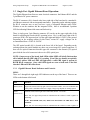
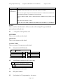
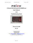
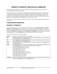
Single Port Gigabit Ethernet
Media Converter Board
(P/N 201350-xxx)
User’s Manual
And
Troubleshooting Guide
August 12, 2009
Rev C
Moog Components Group
Springfield Operations
750 West Sproul Road
Springfield, PA 19064
E-Mail: [email protected] URL: www.moog.com/components
Tel: 610-328-4000 Fax 610-605-6216
24/7 Technical Customer Support Hotline: 610-605-6101
Moog Components Group
Single Port GBE Media Converter Manual
August 12, 2009
MANUAL REVISION HISTORY
REVISION
DATE
BY
NUMBER
REASON FOR
REVISION
A
10/10/07
GSG
ORIGINAL
B
02/17/09
IB
Updated contact information to reflect
Moog Components Group
C
08/12/09
GH
Corrected RJ45 pinout
TABLE OF CONTENTS
1
SINGLE PORT GIGABIT ETHERNET BOARD, P/N: 201350-XXX....................................... 3
1.1
1.2
1.3
SINGLE PORT GIGABIT ETHERNET BOARD REVISION HISTORY: ...................................................... 3
SINGLE PORT GIGABIT ETHERNET BOARD DASH (-) NUMBER DEFINITIONS ................................... 3
SINGLE PORT GIGABIT ETHERNET BOARD OPERATION: .................................................................. 4
1.3.1
1.3.2
1.3.3
1.3.4
1.3.5
1.3.6
1.3.7
Gigabit Ethernet Board Indicators and Controls: .......................................... 4
Single Port Gigabit Ethernet Board Specifications: ....................................... 6
Gigabit Ethernet board Dimensions: .............................................................. 6
Gigabit Ethernet board Power Requirements: ............................................... 6
Power Section Testing..................................................................................... 6
Optical Section Testing ................................................................................... 7
Ethernet Testing .............................................................................................. 7
Page 2 of 7
Moog Components Group
1
Single Port GBE Media Converter Manual
August 12, 2009
Single Port Gigabit Ethernet Board, P/N: 201350-xxx
The Prizm Single Port Gigabit Ethernet Media Converter board provides a fiber optic link to
remote a Gigabit Ethernet. An industry standard pluggable small-form-factor (SFP) Gigabit
Ethernet (GBE) fiber optic module is employed to allow easy customization of the fiber
optic link characteristics. Single mode fiber is typically used with this board and optical
links can easily exceed 10 kilometers. Multimode fiber can also be supported but with
drastically reduced optical link distance – typically less than 1 kilometer depending on the
fiber specifics.
This board has to be linked with another Gigabit Ethernet board to complete the Ethernet
connection.
NOTE: The Gigabit Ethernet board will only work with Gigabit Ethernet devices.
This board will not support 10 or 100 Mbps Ethernet.
The Gigabit Ethernet board will operate as either a subsea or surface interface board, so can
be used as spare for either location. The optical modules used on the board are inherently
bi-directional and care must be taken to ensure the correct optical port (either TX or RX) is
connected, depending on the board configuration and system location. While the optical
module‟s receiver will operate on all of the 16 CWDM (coarse wave division multiplexing)
wavelengths (1270 to 1610nm), the module‟s transmitter only emits at a single wavelength
so care must be taken to ensure the correct wavelength is used.
For non-CWDM applications, Moog Components Group can supply the board with SFP‟s
that contain an internal bi-direction WDM (wave division multiplexers) for single-fiber
operation.
1.1 Single Port Gigabit Ethernet Board Revision History:
The Gigabit Ethernet board has gone through the following printed circuit board (PCB) and
Assembly revisions:
PCB Revision A/Assembly Revision A Original design
1.2 Single Port Gigabit Ethernet Board Dash (-) Number Definitions
The Gigabit Ethernet board has a Dash Number appended to the part number. This Dash
Number identifies the specific board configurations:
-001A original configuration.
Page 3 of 7
Moog Components Group
Single Port GBE Media Converter Manual
August 12, 2009
1.3 Single Port Gigabit Ethernet Board Operation:
The Gigabit Ethernet board has two main electrical connectors: the Ethernet RJ-45 and the
2-pin Phoenix DC power connector.
The RJ-45 connector (J6) is located at the lower right side of the board and is a standard 8pin Ethernet connector with an integrated transformer. Depending on the ordering options,
the RJ-45 connector may or may not have a pair of integrated Ethernet status LEDs.
Whether or not the connector has the integrated LEDs, there is an additional 2-position
LED for indicating Ethernet link status and link activity.
There is single green 2-pin Phoenix connector (J2) on the on the upper right side of the
board for supplying the board with DC operating power. Pin 1 (at the lower right of the J2
connector) is the +DC input and pin 2 (at the upper right and labeled “GND”) is the ground.
Depending on the ordering options for this board, various DC supply voltages can be
accommodated from +5VDC to +24VDC.
The SFP optical module (J4) is located at the lower left of the board. Depending on the
ordering options, the optical module may have one or two integral LC optical connectors. If
there are two optical connectors then the upper left connector is the transmit (TX) optical
port while the lower left connector is the receive (RX) optical port.
NOTE: On power-up of the board, both LEDs within LED3 will briefly flash on then
off to indicate that the GBE chip (U3) is starting. Even if the two boards are optically
connected, neither LED on LED3 will light until a valid GBE signal is present at
BOTH RJ-45 connectors. Once valid GBE signals are seen at both ends of the link
then the LEDs on LED3 will activate.
1.3.1 Gigabit Ethernet Board Indicators and Controls:
LEDS:
There are 3 through-hole right angle LED indicators on the top of the board. There are no
LEDs on the bottom of the board.
LED
Indication
LED1 (Green)
Single LED, located at the top right of the board, labeled „PWR”, serves as an indicator that
+VDC power is available to the board. Supply voltage range depends of ordering options.
LED2
(Green/Green)
Dual LED, located on the right center of the board, labeled „1.2/3.3VDC‟.
When „ON‟, the upper LED provides an indication that the on-board 1.2VDC regulator is
functioning.
NOTE: THE UPPER LED (1.2V) DOES NOT FUNCTION ON THE REV A PCB
VERSION.
When „ON‟, the lower LED provides an indication that the on-board 3.3VDC regulator is
Page 4 of 7
Moog Components Group
Single Port GBE Media Converter Manual
August 12, 2009
functioning.
LED3
(Green/Green)
Dual LED, located on the right center of the board, labeled „COL/FIBR‟.
When „ON‟, the upper LED provides an indication that there is a GBE cable is attached to the
RJ-45 connector and there is an Ethernet device on the cable.
The lower LED will blink „OFF” to indicate that there is Ethernet activity (traffic) on the
cable.
Refer to the note in Section 1.3 above.
NOTE: THE ‘COL/FIBR’ LABEL IS INCORRECT ON THE REV A PCB VERSION.
FUSES:
There is one fuse for this board. All fuses are the self-resetting PTC type and should
quire replacement by the user.
F1:
1.1 Amp PTC, DC input fuse at J2
SWITCHES:
There are no switches on this board.
TRIMPOTS:
There are no trimpots on this board.
CONNECTORS:
There are a total of 6 connectors on the board.
J1:
2x4 pin external LED header
LED Header
J1
+3.3VDC
1 o o 2
LINK1000
GROUND
3 o o 4
LINK100
FIBER MEDIA SELECT
5 o o 6
LINK10
DUPLEX/COLLISION
7 o o 8
NO CONNECT
Note: these pins are not typically available to the user, contact Prizm
J2:
2-pin Phoenix connector for DC power entry
DC Power 2-pin Phoenix Connector
J2
o 1
o 2
GROUND
+VDC INPUT
J3:
No connector on the board
J4:
SFP optical module
J5:
5-pin header for U3 programming – do not use
Page 5 of 7
Moog Components Group
J6:
J7:
Single Port GBE Media Converter Manual
August 12, 2009
8-pin RJ-45 connector/transformer for Ethernet
J6
Gigabit Ethernet
RJ-45 Connector
Pin #
1
2
3
4
5
6
7
8
1000Mbps
A+
AB+
C+
CBD+
D-
Left
Pin #
o o o o o o o o Right
8 7 6 5 4 3 2 1
Reset chip at this location
JUMPER POSTS:
There are no jumper posts on this board.
1.3.2 Single Port Gigabit Ethernet Board Specifications:
Number of Ethernet links:
1 per board
Data rates supported:
Gigabit Ethernet only
1.3.3 Gigabit Ethernet board Dimensions:
Printed circuit board (PCB): 1.90 inches x 4.00 inches
(48.26mm x 101.6 mm)
1.3.4 Gigabit Ethernet board Power Requirements:
The Gigabit Ethernet board utilizes approximately 2.5 Watts of power.
5.0VDC input, approximately 500mA
10.0VDC input, approximately 250mA
12.5VDC input, approximately 200mA
20.0VDC input, approximately 125mA
25.0VDC input, approximately 100mA
1.3.5 Power Section Testing
NOTE: The connectors and components on the bottom of the Gigabit Ethernet board
have pins that are connected to internal supply voltages and ground. If these pins are
inadvertently shorted together or to a common chassis ground, the board fuse (F1) will
trip/reset.
Page 6 of 7
Moog Components Group
Single Port GBE Media Converter Manual
August 12, 2009
If both the “PWR” LED and the “1.2/3.3 VDC” LED is out:
Check for continuity of PTC fuse F1 with an ohmmeter.
Replace PTC fuse if open.
If only the “1.2/3.3 VDC” LED is out:
Verify DC voltage is present at the source
Replace the board with a spare, nothing repairable.
1.3.6 Optical Section Testing
1.3.7 Ethernet Testing
If the Ethernet link is out or has errors:
As this board will only work with Gigabit Ethernet traffic, verify that the devices at both
ends of the link are indeed Gigabit Ethernet devices.
Verify that the Ethernet devices at both ends of the link are powered up.
Verify that both of the dual LEDS at LED3 are lit to confirm Ethernet activity at the RJ45 connector.
Attempt to PING from one device to the other.
If the channel is still not operating correctly, first check the field wiring. If the wiring
appears correct, then first replace the subsea Gigabit Ethernet board with a spare and
check the link again. If the problem is still there, replace the surface Gigabit Ethernet
board, with a spare and check the link again.
Page 7 of 7