1
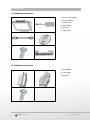
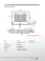
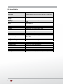
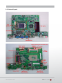
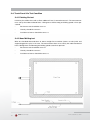
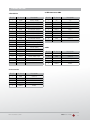
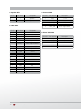
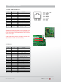
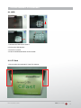
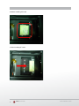
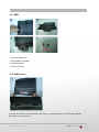
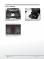
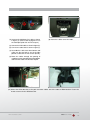
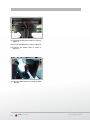
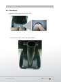
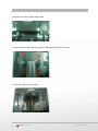
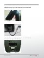
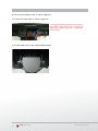
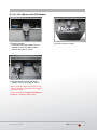
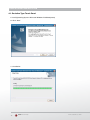
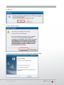
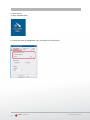
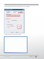
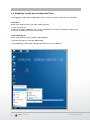
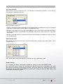
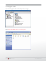
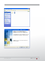
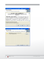
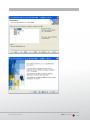
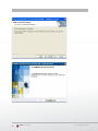
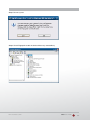
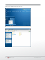
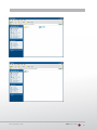
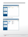
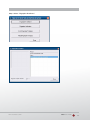
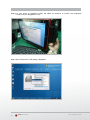
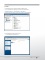
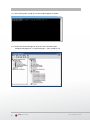
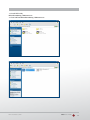
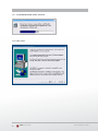
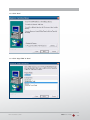
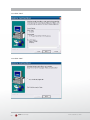
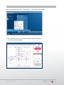
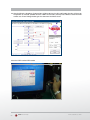
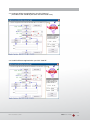
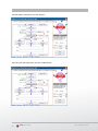
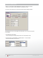
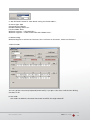
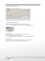
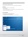
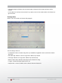
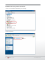
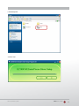
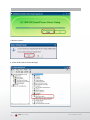
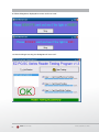
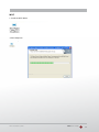
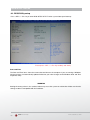
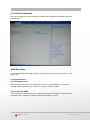
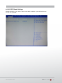
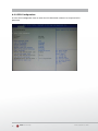
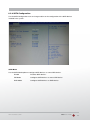
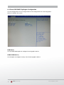
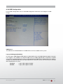
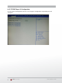
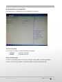
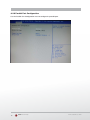
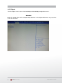
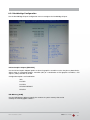
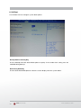
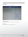
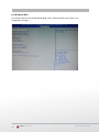
P2300 User Manual Version 1.0 Errors excepted; subject to change www.colormetrics.com.tw 2 Colormetrics P2300 www.colormetrics.com.tw Table of Contents Copyright 4 Safety Instructions 5 Packing List 6 1-1. Standard Accessories 6 System View 7 2-1. Rear View with Optional LPT Port 7 2-2. Specification 8 2-3. Internal Layout 9 Pin Definition11 Rear I/O Interface13 System Assembly & Disassembly15 3-1. HDD 15 3-2. CF- Card 15 3-3. MSR 17 3-4. Cable Cover 17 3-5. 15“ 2nd Display 18 3-6. 8" 2nd Display 21 3-7. 1D / 2D / iButton with RFID Module 25 Device Driver Installation26 4-1. Resistive Type Touch Panel 26 4-2. MagStripe Card Reader Configuration Utility 30 4-3. Fingerprint Reader 34 4-4. RFID 45 Internal VFD (optional)55 5-1. VFD Specification 55 Setup Software Guide56 i-button reader configuration utility59 BIOS/Utility setup68 Advanced BIOS Features 69 Advanced Chipset Features 80 LCD Surface Cleaning 87 CE Notice 88 www.colormetrics.com.tw Colormetrics P2300 3 Copyright Copyright 2010 Publishing. All Rights Reserved. This manual, software and firmware described in it are copyrighted by their respective owners and protected under the laws of the Universal Copyright Convention. You may not reproduce, transmit, transcribe, store in a retrieval system, or translate into any language, in any form or by any means, electronic, mechanical, magnetic, optical, chemical, biological, molecular, manual, or otherwise, any part of this publication without the express written permission of the publisher. All products and trade names described within are mentioned for identification purpose only. No affiliation with or endorsement of the manufacturer is made or implied. Product names and brands appearing in this manual are registered trademarks of their respective companies. The information published herein has been checked for accuracy as of publishing time. No representation or warranties regarding the fitness of this document for any use are made or implied by the publisher. We reserve the right to revise this document or make changes in the specifications of the product described therein at any time without notice and without obligation to notify any person of such revision or change. 4 Colormetrics P2300 www.colormetrics.com.tw Safety Instructions 1. Read these instructions carefully. Keep these instructions for future reference. 2. Please disconnect this equipment from AC outlet before cleaning. Don’t use liquid or sprayed detergent for cleaning. Use moisture sheet or cloth for cleaning. 3. Please keep this equipment from humidity. 4. Lay this equipment on a reliable surface when install. A drop or fall could cause injury. 5. Make sure power cord such a way that people can not step on it. Do not place anything over the power cord. 6. All cautions and warnings on the equipment should be noted. 7. If the equipment is not used for long time, disconnect the equipment from main to avoid being damaged by transient over voltage. 8. Never pour any liquid into opening, this could cause fire or electrical shock. 9. If one of the following situations arises, get the equipment checked by a service personnel: a. The power cord or plug is damaged. b. Liquid has penetrated into the equipment. c. The equipment has been exposed to moisture. d. The equipment does not work well or you can not get it work according to user manual. e. The equipment has dropped and damaged. 10. D o not leave this equipment in an environment unconditioned, storage temperature below -20°C or above 60°C, it may damage the equipment. 11. Unplug the power cord when doing any service or adding optional kits. Lithium Battery Caution: Danger of explosion can happen if the battery is incorrectly replaced, Replace only the original or equivalent type recommended by the manufacture. Dispose used batteries according to the manufacture’s instructions. Do not remove the cover, and ensure no user serviceable components are inside. Take the unit to the service center for service and repair. www.colormetrics.com.tw Colormetrics P2300 5 1 Packing List Packing PackingList List 1-1. Standard Accessories 1-1 Standard Accessories a. b. a. System (with stand) a. System (with stand) b. Power Adapter b. Power Adapter c. Power Cord Cord c. Power d. Driver Bank Bank d. Driver c. d. e. f. e. Screw x2 e. Screw x2 f. Cable Cover f. Cable Cover 1-2. Accessories 1-2Optional Optional Accessories a. a. Single a. Single MSR MSR b. IN 1 MSR b. 3 INb.13MSR c. Screw x2 c. Screw x2 c. 6 | 95 6 Colormetrics P2300 www.colormetrics.com.tw r View Version: 2.0 System View System View System View 2-1. Rear View Standard h Drawer ) ) 4 M 3 external) put ort (Option) ton rt Card/ Fingerprint/ tion) n) st CARD * Please make sure 19V DC plug in the right direction before plugging in DC jack. Item 8. COM2 15.VFD(Option) 1.Mic 9.RJ45(COM 3 external) 16.HDD/CF CARD 2. Line-Out 10.PS2(K/B) 3.RJ11 (Cash Drawer ) 11.19V DC Input 4.RJ45(LAN) 12.Parallel port (Option) 5.USB 2.0 X4 13.Power Button 6. COM1 14.MSR/Smart Card/ i-Button/ Fingerprint/ RFID (Option) 7.VGA www.colormetrics.com.tw Colormetrics P2300 7 2-2. Specification Processor Intel® Celeron® G540 processor (2M Cache, 2.50GHz) Chipsets: North Bridge/South Bridge H61 Memory One SO-DIMM socket supports DDR3 1333MHZ up to 4GB Audio Line-out/Mic-in Network RJ45 10/100/1000 Base-T USB 4*USB 2.0 Storage CFast type I / 2.5” SATA HDD / SSD BIOS AMI UEFI BIOS Power DC 19V 180W Adaptor Thermal Solution Heat sink + Fan X3 Dimension 368 (W) x 264.2 (H) x 285 (D) mm Operating Temperature 0°C ~ 35°C Storage Temperature -20°C ~ 60°C Storage Humidity 20% ~ 80%, non-condensing Display LCD Panel Size 15-inch TFT Active Matrix Display Resolution 1024*768 Pixels Brightness 250 cd/m2 Touch Panel 5-wire Resistive Type / optional Tilt Angle 30°~90° <DC 36W(12V) external power adapter> 8 Colormetrics P2300 www.colormetrics.com.tw Clientron PT6300 User Manual Version: 2.0 Clientron PT6300 User Manual Version: 2.0 2-3 Internal Layout 2-3. Internal Layout 2-3 Internal Layout Colormetrics P2300 www.colormetrics.com.tw 9 | 95 9 Clientron PT6300 User Manual Version: 2.0 2-4 Touch Panel Condition 2-4. Touch Panel LifeLife TestTest Condition 2-4.1 Pointing lifelife test 2-4-1 Pointing test HitHit it thirty fivefive million times withwith a silicon rubber of Rof0.8, Hs 60 measure it. The it thirty million times a silicon rubber R 0.8, Hs and 60 and measure it. The measurement must satisfy the under-metioned items. Hitting force shall be 250g and hitting speed 3 times per measurement must satisfy the under-metioned items. Hitting force shall be 250g and hitting second. speed 3 times per second. - Resistance state should the same 5.1 - Resistance state should the same 5.1 - Linearity should the same 5.2 - Linearity should the same 5.2 - Insulation resistance should the same 5.3 - Insulation resistance should the same 5.3 2-4.2 Hand Writing test 2-4-2 Hand Writing test Write one hundred thousand times of 40mm straight line to and fro (counts as twice) with and Write one hundred thousand times of 40mm straight line to and fro (counts as twice) with and engineering in AAThe area. The measurement items mustthe satisfy the under-mentioned engineering plasticplastic stylus stylus in AA area. measurement items must satisfy items. Writing force shall be 250g and writing speed 3,000 times per hour. under-mentioned items. Writing force shall be 250g and writing speed 3,000 times per hour. - Resistance state should the same 5.1 - Resistance state should the same 5.1 - Linearity should the same 5.2 - Linearity should the same 5.2 - Insulation resistance should the same 5.3 - Insulation resistance should the same 5.3 10 | 95 10 Colormetrics P2300 www.colormetrics.com.tw Pin Definition 3. VFD Connector CN9 1. Parallel J7 Pin NO. Pin Name Description Pin NO. Pin Name Description 1 STB# Printer Strobe 1 5V +5V 2 PD0 Parallel Port DATA0 2 NDSR DSR 3 PD1 Parallel Port DATA1 3 GND Ground 4 PD2 Parallel Port DATA2 4 NRTS DTR 5 PD3 Parallel Port DATA3 5 NRTS RTS 6 PD4 Parallel Port DATA4 6 NCTS CTS 7 PD5 Parallel Port DATA5 7 NTXD TXD 8 PD6 Parallel Port DATA6 8 NRXD RXD 9 PD7 Parallel Port DATA7 9 GND Ground 10 ACK# Printer Acknowledge 10 12C +12V 11 BUSY Printer Busy 12 PE Printer Paper End 13 SLCT Printer Select 14 AFD# Printer Auto Line Feed 15 ERR# Printer Error Pin NO. Pin Name Description 16 INIT# Printer Initialize 1 GND Ground 17 SLIN# Printer Select Input 2 GND Ground 18 GND Ground 3 Mic R Mic right 19 GND Ground 4 Mic L Mic left 20 GND Ground 5 Detect Delect Pin NO. Pin Name Description 1 GND Ground 2 GND Ground 3 Line OUT R Line out 4 Line OUT L Line out 5 Detect Delect 4. Mic 2. Line-out J3 www.colormetrics.com.tw Colormetrics P2300 11 7. Inverter CN14 5. Speaker SP1 Pin NO. Pin Name Description Pin NO. Pin Name Description 1 + Speaker + 1 VCC +12V 2 - Speaker - 2 GND Ground 3 NC NC 4 BKL_CTL Back Light Brightness 5 BKL_EN Back Light Enable 6. LVDS CN 2 Pin NO. Pin Name Description 1 LCDVCC +3.3v 2 LCDVCC +3.3v 3 GND Ground Pin NO. Pin Name Description 4 NC NC 1 VCC +5V 5 DATA 0- LVDS Output DATA0- 2 - DATA D- 6 DATA 0+ LVDS Output DATA0+ 3 + DATA D+ 7 GND Ground 4 GND Ground 8 DATA 1- LVDS Output DATA1- 5 GND Ground 9 DATA 1+ LVDS Output DATA1+ 10 GND Ground 11 DATA 2- LVDS Output DATA2- 12 DATA 2+ LVDS Output DATA2+ 13 GND Ground 14 CLK- LVDS CLK- 15 CLK+ LVDS CLK+ 16 GND Ground 17 NC NC 18 NC NC 19 GND Ground 20 NC NC 12 Colormetrics P2300 8. Extra USB CN13 www.colormetrics.com.tw Pi n 1 2 3 4 Rear I/O Interface Signal Function CD RD TD DTR GND Carrier Detect (IN) Receive Data (IN) Transmit Data(OUT) Data Terminal Ready(OUT) Ground Sign 6 7 8 9 DSR RTS CTS Ring 5 COM4 port . Warning!! COM4 (RJ45 Connector ) for network device. If you are using on the network devic 1. COM1’ COM2’ COM3 port Pin Signal Function 1 CD Carrier Detect (IN) 2 RD Receive Data (IN) 3 TD Transmit Data(OUT) 4 DTR Data Terminal Ready(OUT) 5 GND Ground 6 DSR Data Set Ready (In) 7 RTS Request To Send (OUT) 8 CTS Clear To Send (IN) 9 Ring/5V/12V Setting by BIOS 1 2 3 4 5 6 78 Pin 1: +5V / +12V Pin 2: DSR# Pin 3: GND Pin 4: DTR# Pin 5: RTS# Pin 6: CTS# Pin 7: TxD Pin 8: RxD VGA port COM3 port. Warning!! COM3 (RJ45 Connector ) for external VFD use only. Never use on network device. If you are using on the network device will cause the device damaged. COM 3 port will be inactive if POS has internal VFD. (Alternative of COM 3 or internal VFD) 3. USB port Enlarge JUMP 2. VGA port 4. PS/2 K/B port Pin I/O Function 1 Out Red Video 2 Out Green Video 3 Out Blue Video 4 In Monitor ID 2 5 - TTL Ground (Monitor Self Test) 6 - Red Analogue Ground 7 - Green Analogue Ground 8 - Blue Analogue Ground 9 - Key (Plugged Hole) 10 - Sync Ground 11 In Monitor ID 0 12 In Monitor ID 1 13 Out Horizonal Sync 14 Out Vertical Sync 15 In Monitor ID 3 www.colormetrics.com.tw Pin 12 Colormetrics P2300 13 3. USB port 6. RJ11 port (for Cash drawer) Pin Signal Name Wire Colour Comment 1 Vcc Red Cable Power Pin Signal Name Direction 1 Frame GND - 2 Drawer Kick-out drive signal 1 Output 2 - Data White Data Transfer 3 + Data Green Data Transfer 3 N/C - 4 Ground Black Cable Ground 4 +12V - Shell Shield - Drain Wire 5 N/C - 6 Signal GND - 4. PS/2 K/B port Pin Signal Name 1 Data from Device 2 Not Connected 3 Ground 4 +5V DC 5 Clock 6 Not Connected Example DOS COMMAND for Cash Drawer: 1. Create the file: TEST.TXT 2. Input below contents in TEST.TXT CONTEXT-"000.0” MODE COM5:300 3. Run COMMAND under DOS mode COPY TEST.TXT COM5 7. DC Jack 5. LAN port 14 Pin Signal Name Pin Wire Colour Description 1 DC IN 19V 1 White/Orange Transmit 2 Ground 2 Orange Transmit 3 White/Green Receive 4 Blue Not Used 5 White/Blue Not Used 6 Green Receive 7 White/Brown Not Used 8 Brown Not Used Colormetrics P2300 www.colormetrics.com.tw System Assembly & Disassembly 5 System Assembly & Disassembly 3-1. HDD 5-1. HDD UP thethe HDD cover screw*2 1.1. Unfasten Unfasten HDD cover screw*2 2.2. Pull Pulloutout HDD bracket thethe HDD bracket 3. Fasten the screw*4 4.3. Fasten Placethe thescrew*4 HDD bracket back to the module 4. Place the HDD bracket back to the module 5-2. MSR 3-2. CF-Card 1. Please notice the notched CF Card. This side up. 1. 2. 3. 4. Open the MSR cover Single MSR or 4in1MSR Screw*2 M3x10L Fasten the screw Colormetrics P2300 www.colormetrics.com.tw 5-3. UPS Battery 14 15 Clientron PT6300 User Manual Version: 2.0 PT6300 User Manual Version: 2.0 Clientron 2. Before Installing CF Card. 2. 2. 3. 3. Before Installing CFast Card. Before Installing CFast Card. Installing CFast Card 3.After After Installing CF Card. After Installing CFast Card 16 Colormetrics P2300 16 | 95 16 | 95 www.colormetrics.com.tw 1. 2. 3. 4. Unfasten the HDD cover screw*2 Pull out the HDD bracket Fasten the screw*4 Place the HDD bracket back to the module 3-3. MSR 5-2. MSR PT6300 User Manual Version: 2.0 MSR 1. Open the MSR cover 2. Single MSR or 3-in-1 MSR 3. Screw*2 M3x10L 4. Fasten the screw 1. 2. 3. 4. Open the MSR cover Single MSR or 4in1MSR 1. Open the MSR cover Screw*2 M3x10L 2. Singlethe MSR or 4in1MSR Fasten screw 3. Screw*2 M3x10L 4. Fasten the screw cable 5-3.cover UPS Battery 3-4. Cable Cover 14 the cable cover from bottom and make sure the two latches are on the right position. Assemble the cable cover from bottom and make sure the two latches are on the right position. n 2 screws (M3*5L). Then fasten 2 screws (M3*5L). www.colormetrics.com.tw Colormetrics P2300 17 * Power supply must be replaced to 120W above power adapter. (1) Remove the plastic pole cover from the stand. 3-5. 8"/15" 2nd Display wer supply must be replaced to 120W above power adapter. (2) Install the pole into the socket in clockwise direction. emove the plastic pole cover from the stand. (2) Install the pole into the socket in clockwise direction. nstall the pole into the socket in clockwise direction. (1) R emove the plastic pole cover from the stand. (3) Fasten the four screws (M4*8L) to joint the VESA bracket and the rear cover (2) Install the pole into the socket in clockwise direction. (3) Fasten the four screws (M4*8L) to joint the VESA bracket and the rear cover. asten the four screws (M4*8L) to joint the VESA bracket and the rear cover. (4) Connect the COM port, DC cable as shown in figure . (Please refer to pag 60 to set the COM port pin9 with 12V DC output.) (3) Fasten the four screws (M4*8L) to joint the (5) Connect the VGA cable as shown in figure . VESA bracket and the rear cover. 16 (4) Connect the COM port, DC cable as shown in figure . (Please refer to page 60 to set the COM port pin9 with 12V DC output.) (5) Connect the VGA cable as shown in figure . 16 onnect the COM port, DC cable as shown in figure . (Please refer to page 0 to set the COM port pin9 with 12V DC output.) onnect the VGA cable as shown in figure . 16 18 Colormetrics P2300 www.colormetrics.com.tw nect the COM port, DC cable as shown in figure. (Please refer to page 89 to set the M port pin9 with 12V DC output.) nect the VGA cable as shown in figure. (8) Route the cables through the opening of stand front cover and cable clip at bottom and route the cables into the tube of pole. nect the audio cable as shown in figure. 3 2 1 emble the cable cover from bottom and make sure the two latches are on the right (9) Reeve the cables out of the tube. tion, and fasten the two screws (M3*5L). (4) Connect the COM port, DC cable as shown (9) Reeve the cables out of the tube. in figure (1). (Please refer to page 61 to set the COM port pin9 with 12V DC output.) (5) Connect the VGA cable as shown in figure (2). (6) Connect the audio cable as shown in figure(3). (7) Assemble the cable cover from bottom and make sure the two latches are on the right position, and fasten the two screws (M3*5L). 17 (8) Route the cables through the opening of stand front cover and cable clip at the bottom and route the cables into the tube of pole. ount the VESA bracket on the pole and route cables out of the tube of VESA et. Fasten the thumb screw to fix the VESA bracket. 19 | 95 (10) Mount the VESA bracket on the pole and route cables out of the tube of VES onnect the DC power cable as shown in figure. Fasten theout thumb screw the VESA bracket. onnect the VGA shown figure. (10)cable Mountasthe VESAinbracket on the pole bracket. and route cables of the tubetooffix VESA bracket. Fasten the screw to fix VESA onnect the Audio thumb cable as shown in the figure . bracket. www.colormetrics.com.tw (11) Connect the DC power cable as shown in figure. (12) Connect the VGA cable as shown in figure. Colormetrics P2300 (13) Connect the Audio cable as shown in figure. 19 as shown in figure. (11) Connect the DC power cable wn in figure. sho as le (12) Connect the VGA cab wn in figure. sho as le (13) Connect the Audio cab bracket. VESAcable e of (11) Connect the DC power as shown in figure (1). (14) Put the cable cover on the hing 18 as shown in figure (2). (12) Connect the VGA cable (13) Connect the Audio cable as shown in figure (3). (14) Put the cable cover on the hinge of VESA bracket. 19 20 Colormetrics P2300 www.colormetrics.com.tw 5-8 8” 2nd Display 1. Remove the plastic pole cover from the stand. Clientron PT6300 User Manual Version: 2.0 3-6. 8” 2nd Display plastic pole cover from the stand. 5-81. Remove 8” 2ndtheDisplay 1. Remove the plastic pole cover from the stand. 2. Install the pole into the socket in clockwise direction. 2. Install the pole into the socket in clockwise direction. 2. Install the pole into the socket in clockwise direction. 25 | 95 www.colormetrics.com.tw Colormetrics P2300 21 ntron ntron 3.Connect VGA cable and DC power cable Connect VGA cable and DC power cable ntron PT6300 User Manual Version: 2.0 PT6300 User Manual Version: 2.0 PT6300 User Manual Version: 2.0 Connect VGA cable and DC power cable Connect VGA cable and DC power cable Fasten the four screws (M4*8L) to joint the VESA bracket and the rear cover. 4. Fasten the four screws (M4*8L) to joint the VESA bracket and the rear cover. Fasten the four screws (M4*8L) to joint the VESA bracket and the rear cover. Fasten the four screws (M4*8L) to joint the VESA bracket and the rear cover. Reeve the cables out of the tube. Reeve the cables out of the tube. 5. Reeve the cables out of the tube. Reeve the cables out of the tube. 22 Colormetrics P2300 26 | 95 www.colormetrics.com.tw n PT6300 User Manual Version: 2.0 PT6300 User Manual PT6300 User Manual Version: 2.0 Version: 2.0 n n 6.Mount the VESA bracket on the pole and route cables out of the tube of VESA Mount the VESA bracketFasten on the the polethumb and route cables the tube of VESA bracket. bracket. screw to fixout theof VESA bracket. Mount the VESA bracket on the pole and route cables out of the tube astenthe theVESA thumbbracket screw to the VESA Mount onfix the pole andbracket. route cables out of the tube of of VESA VESA bracket. bracket. asten asten the the thumb thumb screw screw to to fix fix the the VESA VESA bracket. bracket. 7.Reeve the cables out from the bottom of pole. eeve the cables out from the bottom of pole. eeve eeve the the cables cables out out from from the the bottom bottom of of pole. pole. oute the cables through the opening of stand front cover and cable clip at the bottom the cables through the opening of cover cable clip at bottom doute route cables into the tube of through pole. 8.Route thefront opening stand front cover and cable clip at the oute thethe cables through thecables opening of stand stand front coverofand and cable clip at the the bottom bottom and routeofthe cables into the tube of pole. d d route route the the cables cables into into the the tube tube of pole. pole. Colormetrics P2300 www.colormetrics.com.tw 27 | 95 23 ron tron PT6300 User Manual 2.0 PT6300 Version: User Manual Version: 2.0 Connect the DC power cable as shown in figure. Connect the DC power cable as shown in figure. 9. Connect DCDC power cable shown in figure (1).refer to page 89, To setup COM port PIN9 withthe 12V output fromasBIOS setup, please To setup COM port PIN9 with 12V DC output from BIOS setup, please refer to page 89, Advanced Chipset Features / COM port PIN9 setting. 10. Connect VGA port cablePIN9 as shown in figure (2). Advanced Chipset Featuresthe / COM setting. Connect the VGA cable as shown in figure. Connect the VGA cable as shown in figure. To setup COM port PIN9 with 12V DC output from BIOS setup, please refer to page 89, Advanced Chipset Features / COM port PIN9 setting. 2 2 1 1 Put the cable cover VESA 11. on Putthe thehinge cableofcover onbracket. the hinge of VESA bracket. Put the cable cover on the hinge of VESA bracket. 24 28 | 95 Colormetrics P2300 28 | 95 www.colormetrics.com.tw 3-7. 1D / 2D / iButton with RFID Module (1) Cable installation. For iButton with RFID module; For 2D barcode scanner with RFID module: Connect the cable as shown. (3) Fix the screws as shown. (2) For 1D barcode scanner with RFID module: Connect the cable as shown. * Before COM port cable connection, please setup COM port PIN9 with 5V DC output from BIOS setup. Please refer to page 83,Advanced Chipset Features / COM port PIN9 setting. www.colormetrics.com.tw Colormetrics P2300 25 Device Driver Installation 4-1. Resistive Type Touch Panel Device Driver Installation 1. Install (Operating System: Microsoft Windows POSReady2009) 6-1. Resistive Type Touch Panel 1.1 ClickSystem: “Next” Microsoft Windows POSReady2009) 1. Install (Operating 1.1 Click Next Device Driver Installation 6-1. Resistive Type Touch Panel 1. Install (Operating System: Microsoft Windows POSReady2009) 1.1 Click Next 1.2 Installation 1.2 Installation 1.2 Installation 26 Colormetrics P2300 25 www.colormetrics.com.tw 1.3 Click Yes 1.3 Click 3 Click Yes Yes 3 Click Yes 1.4 Click Continue Anyway 4 Click Continue 1.4 ClickAnyway Continue Anyway 4 Click Continue Anyway 1.6 Click Finish to reboot system to complete the installation of POS 6 Click Finish to reboot youryour system to complete the installation of POS 1.6 Click Finish to reboot your system to complete the installation ofof POS 6 Click Finish to reboot your system to complete the installation POS driver. uchtouch driver. uch driver. www.colormetrics.com.tw 26 26 26 Colormetrics P2300 27 2. Touch Sensor Click TouchSet 2.2.1 Touch SensorUtility Calibration 2.1 Click TouchSet Utility 2. Touch Sensor Calibration 2.1 Click TouchSet Utility 2-1 Check the sheet of Configurationyou can find the I/F of touch panel 2-1 Check the sheet of Configuration,you can find the I/F of touch panel 2-1 Check the sheet of Configurationyou can find the I/F of touch panel 28 Colormetrics P2300 www.colormetrics.com.tw 27 2.2 Click Calibration folder and check Calibrate box to start Touch Calibration. 2.2 Click Calibration folder and check Calibrate box to start Touch Calibration. 2.2 Click Calibration folder and check Calibrate box to start Touch Calibration. 2.3 Follow the instruction to touch four cross points. 2.3 Follow to to touch four cross points. 2.3 Followthe theinstruction instruction touch four cross points. 28 www.colormetrics.com.tw 28 Colormetrics P2300 29 4-2. MagStripe Card Reader Configuration Utility The MagStripe Card Reader Configuration Utility is used to set up the output format of HID MSR . Installation Below steps guide you how to install the Utility program. 1 Insert the setup CD 2 Run the HID_MSR_PSW00003_V2_0_0.exe setup file that is located in the Software folder of CD. 3 Follow the wizard to complete the installation. Launching Program Below steps guide you how to load the Utility program. 1 From Start/Programs, click HID_MSR2 folder 2 Click MagStripe Card Reader Configuration Utility to launch the program. 30 Colormetrics P2300 www.colormetrics.com.tw 1 The utility program will detect the connected reader. If detected, all the input text boxes will be enabled. 2 If the reader has not been connected to PC yet, please connect the reader and then click Refresh to get connected. Configuration Below is the main window of Utility program. For the settings, there are: 1 L anguage: The language defines the code positions of the keyboard. Each language should use its own settings. Wrong language selected will cause the wrong character displayed. 2 P refix/Suffix: Defines the data string which you would like to append in front or end of the MSR data string. 3 Error Message: Indicates which track number cause the error. 4 Delimiter: Indicates the swipe result. 5 ISO: Define start and end sentinel character. 6 Decode Mode: Determines the way of outputting the three tracks data. Shown below is the data structure of the output string for MSR. PP PR1 SS1 TK1 ES1 SU1 PR2 SS2 TK2 ES2 SU2 PR3 SS3 TK3 ES3 SU3 SU DM www.colormetrics.com.tw Colormetrics P2300 31 1 PP: Prefix for package. 1 SU2: Suffix for track 2. 2 PR1: Prefix for track 1. 2 PR3: Prefix for track 3. 3 SS1: Start sentinel for track 1. 3 SS3: Start sentinel for track 3. 4TK1: Data for track 1, if error happens, using Error Message instead. 4TK3: Data for track 3, if error happens, using Error Message instead.. 5 ES1: End sentinel for track 1. 5 ES3: End sentinel for track 3. 6 SU1: Suffix for track 1. 6 SU3: Suffix for track 3. 7 PR2: Prefix for track 2. 7 SU: Suffix for package. 8 SS2: Start sentinel for track 2. 8 DM: Delimiter for the swipe result. 9TK2: Data for track 2, if error happens, using Error Message instead. 10 ES2: End sentinel for track 2. Prefix/Suffix In default, the prefix and suffix settings are all keep blank. There are 4 kinds of prefix and suffix to be defined, which are: 1 P ackage: For the prefix string, it is appended in the front of the whole MSR data. For the suffix, it is appended in the end of the whole MSR data. In most case, the suffix for package is always to be the “Enter” or “Tab” character. The max data length of the prefix and suffix for the package can be up to 127. 2 T K1: For the prefix string, it is appended in the front of the start sentinel of track 2. For the suffix, it is appended in the end of the end sentinel of track 2. The max data length of the prefix and suffix for the TK1 can be up to 127. 3 T K2: For the prefix string, it is appended in the front of the start sentinel of track 2. For the suffix, it is appended in the end of the end sentinel of track 2. The max data length of the prefix and suffix for the TK1 can be up to 127. 4 T K3: For the prefix string, it is appended in the front of the start sentinel of track 3. For the suffix, it is appended in the end of the end sentinel of track 3. The max data length of the prefix and suffix for the TK1 can be up to 127. ISO This group defines the start and end sentinel for each track. The sentinel is always used to extract the track data from the whole MSR data string. The data length for each sentinel is fixed to one character. Because there is ISO standard that defining the start and end sentinel for the three tracks. For the compatible reason, please do not modify the default value if possible. Decode Mode For this group, it contains two kinds of settings, which are: 1 Track Data Filtering: Determine which track to be, not to be output or needed to be output. 2 Switch Output Order: Change the output order of track 1 ~ 3. 32 Colormetrics P2300 www.colormetrics.com.tw Track Data Filtering Shown below is the filter setting for track 1. This provides a fool-proofing method in case of receiving unwanted or uncompleted track data. These three filter settings are: 1 Enable: If selected, the data of specified track will be packaged in the MSR data string. If the specified track data is not decoded, it will leave blank in the MSR data string. 2 Required: If selected, which means the output MSR data string must contain the specified track data. If the specified track data is not decoded, even MSR data string contains other track data, it will still not to be output. 3 Disable: If selected, the data of specified track will not be packaged in the MSR data string. No matter it is decoded or not. Switch Output Order Show below is the selection of the three track data output order (sequence). The default order is Track 1–Track 2–Track 3. There 6 orders allow to be selected. Please select one to fit your application needs. Update Settings Once complete the settings, click Update to update the settings to connected HID MSR reader. Save Settings To save the settings to a file, click Save; specify the file name and location to be saved. Open Settings To load pre-saved settings, click Open, specify the settings file, and then click OK to load into program. Restore MSR Reader Settings To load restore settings of connected MSR reader, click Restore ES2: End sentinel for track. www.colormetrics.com.tw Colormetrics P2300 33 4-3. Fingerprint Reader Step 1 Check Fingerprint reader be detected by “Device manager” Step 2 Unzip and run Setup.exe from the following folder. 34 Colormetrics P2300 www.colormetrics.com.tw www.colormetrics.com.tw Colormetrics P2300 35 36 Colormetrics P2300 www.colormetrics.com.tw www.colormetrics.com.tw Colormetrics P2300 37 38 Colormetrics P2300 www.colormetrics.com.tw Step 3 Restart system Step 4 Check Fingerprint reader in device without any extraordinary. www.colormetrics.com.tw Colormetrics P2300 39 Step 5 Launch Fingerprint reader from start menu 40 Colormetrics P2300 www.colormetrics.com.tw www.colormetrics.com.tw Colormetrics P2300 41 Step 6 Enroll the fingerprint by the “enrollment” 42 Colormetrics P2300 www.colormetrics.com.tw Step 7 Select “Fingerprint Enrollment” www.colormetrics.com.tw Colormetrics P2300 43 Step 8 Put your finger on fingerprint reader and follow the direction to enroller your fingerprint, it need scan your fingerprint 4 times Step 9 after enroller finish it will popup a dialog box 44 Colormetrics P2300 www.colormetrics.com.tw 4-4. RFID 1. Install (Operating System: Microsoft Windows POSReady 2009) 1.2.2 1.1 Check the Device Manager to verify the status of RFID reader. Computer Management -> Device Manager -> Other devices (The device will show a question mark if the installation is not done properly.) 1.2 Install RFID driver file name: XP2KxVista.exe 2-1 Path:\USB Driver\ XP2KxVista.exe www.colormetrics.com.tw Colormetrics P2300 45 1.2.1 After clicking Next, A pop up console window appears as below. 1.2.2 Check the Device Manager to verify the status of RFID reader. Computer Management -> Device Manager -> Ports (COM & LPT) 46 Colormetrics P2300 www.colormetrics.com.tw 1.3 install RFID utility MifareDemoSetup_PSW00020.exe 3-1 Path:\MF320\MifareDemoSetup_PSW00020.exe www.colormetrics.com.tw Colormetrics P2300 47 1.3.1 InstallaShield Wizard will be activated. 1.3.2 Click “Next” 48 Colormetrics P2300 www.colormetrics.com.tw 1.3.3 Click “Next” 1.3.4 Click “Giga-TMS” & “Next” www.colormetrics.com.tw Colormetrics P2300 49 1.3.5 Click “Next” 1.3.6 Click “Next” 50 Colormetrics P2300 www.colormetrics.com.tw 2 Run RFID demo program. Start -> All Programs -> GIGA-TMS -> Mifare Demo 2-1 R un “Auto Scan” Demo AP will detect the RFID reader automatically. Or select the RFID COM port www.colormetrics.com.tw Colormetrics P2300 51 2-2 After finishing the AutoScan, Request box will be ready for the click and Reader Version will show on the position as marked. (Reader Version: PGM-T1235 V1.0R3 (101230) Place Mifare Card to the RFID reader area. Event Dialog window gets the data from the Mifare Card Close the RFID card to RFID reader 52 Colormetrics P2300 www.colormetrics.com.tw 2-3 Card type will be recognized when you click “Request”. (Your Mifare card should be placed on the RFID reader area.) 2-4 Card ID will be recognized when you click “Card ID”. www.colormetrics.com.tw Colormetrics P2300 53 2-5 SAK will be read when you click “Select”. 2-6 The result will show when you click “Authenticate” 54 Colormetrics P2300 www.colormetrics.com.tw Internal VFD (optional) 5-1. VFD Specification General Display Method Vaccum Fluorescent Display (Blue-green) Number of characters 40 (20 columns x 2 lines) Brightness 500~1000 cd/m2 Character front 5x7 dot matrix Character type 95 Alphanumeric, 32 International Charaters Character size 6.75(H) x 3.75(W) mm Dot size (X xY) 0.55x0.75 mm Download charaters 9 charaters Height 4.70" (120mm) with stand-alone base 9.80" (250mm) with base and 1 extension Panel Dimension 75(H)x170(W)x50(D) mm Pole Dimension Per support length: 130 mm Base Dimension 33(H)x159.8(W)x100(D) mm Viewing Angle Max. 90° Horizontal Rotation Max. 355° Weight Approx. 980 grams Commands Mode LD220, EPSON, AEDEX, UTC/S, UTC/P, ADM788, DSP800, CD5220, EMAX, LOGIC CONTROL, Ultimate Language Support US English, Int´l English, Bosnia, Croatian, Czech, Danish, Dutch, Estonain, Faroese, Finnish, Flemish, French, Fr Canadian, German, Greek, Hebrew, Hungarian, Icelandic, Indonesian, Irish, Italian, Katakana, Lativian, Lithuanian, Norwegian, Polish, Portuguese, Romanian, Russian, Slovene, Slovak, Spanish, Swedish Interface RS-232 (serial) / USB Reliability Baud rate Direct connection 9600 or 19,200 bps Connection MTBF 30,000 hours Power Consumption 5~12 VDC Safety EMC standards Safety standards FCC, CE www.colormetrics.com.tw Colormetrics P2300 55 Setup Software Guide 1 Power on, and waiting test page of EEPROM test, Baud rate, and Command page. And you may set up the customer display by “VFD_Setup.exe” Utility. 2. To execute “VFD_Setup.exe” for setup communication between display and Utility The Baud Rate will show on states page of the Utility (Note: You may check it when power on the display) 3. “Get Setting From VFD” button To get all setting from the display and It´ll refresh the “VFD_Setup.exe” utility 4. “Character Type” / “Comand Mode” / “BaudRate Selcet” / “Passthru Mode” Please refer to Chapter 4-5 user manual 62 62 56 Colormetrics P2300 www.colormetrics.com.tw 5. “Set All Default” button To show default setting, the Default table is, Character Type: USA Command Type: EPSON BaudRate Setting: 9600/n/8/1 Passthru Mode: None Welcome msg line1: ***VFD DISPLAY*** Welcome msg line2: ***HAVE A NICE DAY AND THANK YOU*** 6. Welcome Msg Welcome Msg line1 maximum 20 characters, line 2 maximum 20 characters, total of 40 characters. a. ASCCII mode You can type the character by keyboard (0x20h˜0x7Fh), if you press clear icon, it will clear the all Msg charaters on AP. b. Hex mode Hex mode can define the character from 0x20h to 0xFFh, the range 0x80˜0xFF 63 63 www.colormetrics.com.tw Colormetrics P2300 57 Clientron PT6300 User Manual Version: 2.0 PT6300 User Manual Version: 2.0 Clientron wich depends on the code page table. Like the first character (0x80) in default code page will show Ç on display 7. “Download setting to VFD” button This button is to download the setting from VFD_Setup.exe to display. *After success dialog „Download O.K.! Please restart!“ message popped up, you 8. “Save” button To save user´s setting in file, example: below picture to save file name as „Rename-Goodluck“ file set for Welcome Msg. P.S: The default setting named „VFD.vfd“ which can´t be made any setting change. 9. “Load” button For saving your time, you could load any setting file which you made before the display. You must restart the display for enable the new settings. 58 Colormetrics P2300 65 | 95 65 | 95 www.colormetrics.com.tw Clientron PT6300 User Manual Version: 2.0 i-Button Reader Configuration Utility 6-6 i-Button Reader Configuration Utility The i-Button Reader Configuration Utility is used to set up the output format of HID MSR The i-Button Reader Configuration Utility is used to set up the output format of HID MSR Installation Installation Below steps guide you how to install the Utility program. Below steps guide you how to install the Utility program. • Insert the setup CD. Insert the setup CD • thethe HID_MSR_PSW00003_V2_0_0.exe setup file that is located in the Software folder of CD. RunRun HID_MSR_PSW00003_V2_0_0.exe setup file that is located in the Software • Follow the wizard to complete the installation. folder of CD. Follow the wizard to complete the installation. Launching Program Launching Program Below steps guide you how to load the Utility program. Below steps guide you how to load the Utility program. • From Start/Programs, click HID_MSR2 folder. From Start/Programs, click HID_MSR2 folder • Click MagStripe Card Reader Configuration Utility to launch the program. Click MagStripe Card Reader Configuration Utility to launch the program. www.colormetrics.com.tw 66 | 95 Colormetrics P2300 59 Clientron PT6300 User Manual Version: 2.0 The utility program will detect the connected reader. If detected, all the input text boxes will be enabled. the reader has not to PC reader. yet, please connectall thethe reader click • TheIf utility program will been detectconnected the connected If detected, inputand textthen boxes will be enabled. Refresh to get connected. • If the reader has not been connected to PC yet, please connect the reader and then click Refresh to get connected. Configuration Configuration Below is is the the main mainwindow windowofofi-Button i-ButtonUtility Utilityprogram. program. Below For the settings, there are: For the settings, there are: • Prefix/Suffix: Defines the data string which you would like to append in front or end of the i-Button key string. Prefix/Suffix: Defines the data string which you would like to append in front or end of •Error Indicates theMessage: i-Button key string. error message when i-Button key read fail. IndicatesIndicates messageerror when i-Buttonwhen key read correctly. • Message: Error Message: message i-Button key read fail. : DefineIndicates Start and End sentinel for the ID string. •SS/ES Message: message when byte i-Button keyi-Button read correctly : i-Button length from byte 0~16.for the i-Button ID string • Length SS/ES : Define ID Start and request End sentinel order : 4 format could be selectfrom at Attach •Output Length : i-Button ID length request 0~16 /Remove i-Button ID. Output order : 4 format could be select at Attach /Remove i-Button ID 67 | 95 60 Colormetrics P2300 www.colormetrics.com.tw Clientron PT6300 User Manual Version: 2.0 Update Settings Once complete the settings, click Update to update the settings to connected HID MSR reader. Update Settings Savecomplete Settings Once the settings, click Update to update the settings to connected HID MSR To save the settings to a file, click Save; specify the file name and location to be saved. reader. Open Settings To load pre-saved settings, click Open, specify the settings file, and then click OK to load into program. Save Settings To save theMSR settings to a file,Settings click Save; specify the file name and location to be saved. Restore Reader To load restore settings of connected MSR reader, click Restore ES2: End sentinel for track. Open Settings To load pre-saved settings, click Open, specify the settings file, and then click OK to load into program. Restore MSR Reader Settings To load restore settings of connected MSR reader, click Restore ES2: End sentinel for track. Colormetrics P2300 www.colormetrics.com.tw 68 | 95 61 Clientron Clientron PT6300 PT6300 User User Manual Manual Version: Version: 2.0 2.0 Installation and Testing of Smart Card Reader 6-7 6-7 Installation Installation and and Testing Testing of of Smart Smart Card Card Reader Reader 1. Check smart card reader be detected by “Device manager”. 1. Check 1. Check smart smart card card reader reader be be detected detected by by “Device “Device manager”. manager”. 2. Install the SCR driver. 2. 2. Install Install the the SCR SCR driver. driver. 62 Colormetrics P2300 69 69 || 95 95 www.colormetrics.com.tw Clientron Clientron PT6300 PT6300 User User Manual Manual Version: Version: 2.0 2.0 3. Run Setup.exe. 3. 3. Run Run Setup.exe. Setup.exe. 4. Click “Yes”. 4. 4. Click Click “Yes”. “Yes”. www.colormetrics.com.tw 70 70 || 95 95 Colormetrics P2300 63 Clientron Clientron Clientron PT6300 User Manual PT6300 User Manual Version: 2.0 Version: 2.0 PT6300 User Manual Version: 2.0 5. Restart systems. 5. 5. Restart Restart systems. systems. 5. Restart systems. 6. Check SCR reader in Device Manager. 6. Check SCR SCR reader reader in in Device Device Manager. Manager. 6. Check 6. Check SCR reader in Device Manager. 64 Colormetrics P2300 71 | 95 71 | 95 71 | 95 www.colormetrics.com.tw Clientron PT6300 User Manual Version: 2.0 Clientron PT6300 User Manual Version: 2.0 7. Run the testing program – EZ100test. 7. Run the testing program – EZ100test. 7. Run the testing program – EZ100test. 8. Conferm that SCR can be detected by the testing program, then run the program - the 8. Conferm that SCR can be detected by the testing program, then run the program - the Start Testing. Start Testing. 8. Conferm that SCR can be detected by the testing program, then run the program - the Start Testing. www.colormetrics.com.tw 72 | 95 72 | 95 Colormetrics P2300 65 Clientron Clientron 9. Follow dialog boxes displayed to remove and insert card. 9. Follow dialog boxes displayed to remove and insert card. 9. Follow dialog boxes displayed to remove and insert card. PT6300 User Manual Version: 2.0 PT6300 User Manual Version: 2.0 10. After the testing, testing, the the dialog dialog box boxwill willshow show“oK”. “oK”. 10. After finishing finishing the 10. After finishing the testing, the dialog box will show “oK”. 66 Colormetrics P2300 73 | 95 73 | 95 www.colormetrics.com.tw Clientron Clientron PT6300 User Manual PT6300 User Manual Version: 2.0 Version: 2.0 6-7 Wi-Fi 6-7 Wi-Fi Wi-Fi 1.1. Install Install the the Wi-Fi Wi-Fi driver. driver. 1. Install the Wi-Fi driver. 2. Run Setup.exe. 2. Run Setup.exe. 2. Run Setup.exe. 74 | 95 74 | 95 www.colormetrics.com.tw Colormetrics P2300 67 BIOS/Utility setup 6-1. BIOS/Utility setup Press <DEL > / <F2> key to enter BIOS SETUP UTILITY when system boot up.m boot up. Please press <DEL > / <F2> key tenderly and slowly. Date and Time The Date and Time items show the current date and time on the computer. If you are running a Windows OS, these items are automatically updated whenever you make changes to the Windows Date and Time Properties utility. WARNING Setting the wrong values in the sections below may cause the system to malfunction. Make sure that the settings made are compatible with the hardware. 68 Colormetrics P2300 www.colormetrics.com.tw Clientron PT6300 User Manual Version: 2.0 7-1Advanced Advanced 6-2. Use the Advanced menu to configure the CPU and peripheral devices through the following Use the Advanced menu to configure the CPU and peripheral devices through the following sub-menus: sub-menus: 76 | 95 www.colormetrics.com.tw Colormetrics P2300 69 Clientron PT6300 User Manual Version: 2.0 7-1-1 ACPI Configuration 6-2.1 ACPI Configuration The ACPI ACPI Configuration Configuration menu The menu configures configures the the Advanced Advanced Configuration Configurationand andPower PowerInterface Interface (ACPI) options (ACPI) options ACPI Sleep State ACPI Stateoption to specify the sleep state the system enters when it is not Use the ACPISleep Sleep State beingUse used. the ACPI Sleep State option to specify the sleep state the system enters when it is not being used. 1. Suspend Disabled 1. Suspend Disabled 2. S1 (CPU Stop Clock) 2. S1 (CPU Stop Clock) DEFAULT The system enters S1 (POS) sleep state. The system appears off. The CPU is DEFAULT The system enters is S1running (POS) sleep state. Themode. system appears off. The stopped; RAM is refreshed; the system in a low power CPU is stopped; RAM is refreshed; the system is running in a low power mode. S3 (Suspend to RAM) 3. S33. (Suspend to RAM) andisthe CPU isoff. powered Power to isthe RAM is The The cachesThe arecaches flushedare andflushed the CPU powered Poweroff. to the RAM maintained. computer returns slower to computer a workingreturns state, but more is saved. maintained. The slower to power a working state, but more power is saved. 77 | 95 70 Colormetrics P2300 www.colormetrics.com.tw Clientron PT6300 User Manual Version: 2.0 7-1-2 S5 RTC Wake Settings 6-2.2 S5 RTC Wake Settings Enable or disable system Whenenabled, enabled,system systemwill willwake wakeon onthe the system wake wake on on alarm alarm event. event. When hr::min::sec specified. hr::min::sec specified. 78 | 95 www.colormetrics.com.tw Colormetrics P2300 71 Clientron PT6300 User Manual Version: 2.0 7-1-3 CPU Configuration 6-2.3 CPU Configuration Use the the CPU CPU Configuration Configurationmenu menuto toenter enterthe theCPU CPUInformation Informationsubmenu submenuororsetup setupIntel IntelCPU CPU Use parameter. parameter. 79 | 95 72 Colormetrics P2300 www.colormetrics.com.tw Clientron PT6300 User Manual Version: 2.0 7-1-4 SATA Configuration 6-2.4 SATA Configuration Use menu to to change change and/or and/orset setthe theconfiguration configurationofofthe theSATA SATAdevices devices Use the the SATA SATA Configuration Configuration menu installed in the system. installed in the system. SATA Mode SATA Mode Use the SATA Mode option to configure SATA devices as normal IDE devices. Use the SATA Mode option to configure SATA devices as normal IDE devices. Disable Disables SATA devices. Disable Disables SATA devices. IDE Mode Configures SATA devices as normal IDE device. IDE Mode Configures SATA devices as normal IDE device. RAID Mode Configures SATA devices as RAID device. RAID Mode Configures SATA devices as RAID device. 80 | 95 www.colormetrics.com.tw Colormetrics P2300 73 Clientron PT6300 User Manual Version: 2.0 7-1-5 Intel IGD SWSCI OpRegion Configuration 6-2.5 Intel IGD SWSCI OpRegion Configuration Use the the Configuration Configuration menu Use menu to to change change and/or and/orset setthe theconfiguration configurationofofthe theinternal internalgraphics graphics devices installed in the system. devices installed in the system. DVMT Mode Use the DVMTMode Mode option to configure internal graphics device. DVMT Use the DVMT Mode option to configure internal graphics device. DVMT/FIXED Memory Use the option to configure memory size of internal graphics device. DVMT/FIXED Memory Use the option to configure memory size of internal graphics device. 81 | 95 74 Colormetrics P2300 www.colormetrics.com.tw Clientron PT6300 User Manual Version: 2.0 7-1-6 USB Configuration 6-2.6 USB Configuration Use the the USB Use USB Configuration Configuration menu menu to to read read USB USB configuration configurationinformation informationand andconfigure configurethe the USB settings. USB settings. USB Devices The USB Enabled field lists the USB devices that are enabled on the system. USBDevices Devices The USB Devices Enabled field lists the USB devices that are enabled on the system Legacy USB Support [Enabled] Use the LegacyUSB USB Support Support BIOS option to enable USB mouse and USB keyboard support. Normally Legacy [Enabled] if this option is not enabled, any attached USB mouse or USB keyboard does not become available Use the Legacy USB Support BIOS option to enable USB mouse and USB keyboard until a USB compatible operating system is fully booted with all USB drivers loaded. When this option is support. Normally USB if thismouse option or is not enabled, anycan attached mouse or USB enabled, any attached USB keyboard controlUSB the system even when there is no USB driver loaded onto the system. keyboard does not become available until a USB compatible operating system is fully Disabled Legacy USB support disabled booted with all USB drivers loaded. When this option is enabled, any attached USB Enabled Legacy USB support enabled mouse or USB keyboard can control the system even when there is no USB driver loaded onto the system. Disabled Legacy USB support disabled Enabled Legacy USB support enabled 82 | 95 www.colormetrics.com.tw Colormetrics P2300 75 Clientron PT6300 User Manual Version: 2.0 7-1-7 IT8783F Super IO Configuration 6-2.7 IT8783F Super IO Configuration Use the Super IO Configuration menu to set or change the configurations for parallel ports and Use the Super IO Configuration menu to set or change the configurations for parallel ports and ports. serial ports. 83 | 95 76 Colormetrics P2300 www.colormetrics.com.tw Clientron PT6300 User Manual Version: 2.0 6-2.8 Serial Port n Configuration Serial Port n Configuration Use the Serial Port n Configuration menu to configure the serial port n. Use the Serial Port n Configuration menu to configure the serial port n. SerialSerial Port [Enabled] Port [Enabled] Use the Port option to enable or disable the serial port.port. UseSerial the Serial Port option to enable or disable the serial Disabled Disabled Disable Disable the the serial serial port port Enabled Enable the serial Enabled Enable the serial port port Change Settings [Auto] Change Settings [Auto] Use the Settings option to change the serial port port IO port address andand interrupt address. UseChange the Change Settings option to change the serial IO port address interrupt Auto The serial port IO port address and interrupt address are automatically detected. address. Auto The serial port IO port address and interrupt address are automatically detected. Colormetrics P2300 www.colormetrics.com.tw 84 | 95 77 Clientron PT6300 User Manual Version: 2.0 7-1-7 Parallel Port Configuration 6-2.9 Parallel Port Configuration Use the Parallel Port Configuration menu to configure the parallel port. Use the Parallel Port Configuration menu to configure the parallel port. 78 Colormetrics P2300 85 | 95 www.colormetrics.com.tw Clientron PT6300 User Manual Version: 2.0 7-1-8 H/W Monitor 6-2.10 H/W Monitor The Monitor menu menu shows showsthe theoperating operatingtemperature temperatureand andfan fanspeeds. speeds. The H/W H/W Monitor 86 | 95 www.colormetrics.com.tw Colormetrics P2300 79 Clientron PT6300 User Manual Version: 2.0 7-2 Chipset Chipset 6-3. Use the Chipset menu to access the Northbridge and Southbridge configuration menus. Use the Chipset menu to access the Northbridge and Southbridge configuration menus WARNING WARNING! Setting the wrong values for for thethe Chipset BIOS selections BIOS menu menu may may cause the Setting the wrong values Chipset BIOS selectionsininthe the Chipset Chipset BIOS system to malfunction. cause the system to malfunction. 80 Colormetrics P2300 87 | 95 www.colormetrics.com.tw Clientron PT6300 User Manual Version: 2.0 7-2-1 Northbridge Configuration 6-3.1 Northbridge Configuration Use the Northbridge Chipset Configuration menu to configure the Northbridge chipset. Use the Northbridge Chipset Configuration menu to configure the Northbridge chipset. Initiate Graphic Adapter [PEG/IGD] Initiate Graphic Adapter [PEG/IGD] Use the Initiate Graphic Adapter option to select the graphics controller used as the primary boot device. the an Initiate Graphicgraphics Adapter controller option to select controller used as the controller, a PCI SelectUse either integrated (IGD) the or agraphics combination of PCI graphics express (PEG) controller or an IGD. primary boot device. Select either an integrated graphics controller (IGD) or a Configuration options are listed below: combination of PCI graphics controller, a PCI express (PEG) controller or an IGD. IGD Configuration options are listed below: IGD PCI/IGD PCI/IGD PCI/PEG PCI/PEG PEG/IGD DEFAULT PEG/IGD PEG/PCI DEFAULT PEG/PCI IGD Memory [64 M] Use the IGD Memory option IGD Memory [64 M]to specify the amount of system memory that can be used by the internal graphics device. Use the IGD Memory option to specify the amount of system memory that can be used by the internal graphics device www.colormetrics.com.tw 88 | 95 Colormetrics P2300 81 Clientron PT6300 User Manual Version: 2.0 7-2-2 Southbridge Configuration 6-3.2 Southbridge Configuration Use the Southbridge Configuration menu to configure the Southbridge chipset. Use the Southbridge Configuration menu to configure the Southbridge chipset. Serial Port 1/2 Voltage Select [STD] Serial Port 1/2 Voltage Select [STD] Select „COM1/2 PIN9 Function“ and press <Enter> to setup COM 1/2 PIN9 function. Select "COM1/2 PIN9 Function" and press <Enter> to setup COM 1/2 PIN9 function. ITEM ITEM COM1 PIN9 Function COM1 Function COM2 PIN9PIN9 Function COM2 PIN9 Function 82 Colormetrics P2300 Option Option STD (Default) 5V 12V STD (Default) Descriptions Descriptions COM1/2 Pin9 select RING function Pin9 select RING function COM1/2 Pin9COM1/2 select 5V/12V function 5V 12V 89 | 95 COM1/2 Pin9 select 5V/12V function www.colormetrics.com.tw Clientron PT6300 User Manual Version: 2.0 7-2-3 ME Subsystem 6-3.3 ME Subsystem Use menu to to configure configure the the Intel® Intel®Management ManagementEngine Engine(ME) (ME) configuration configuration Use the the ME ME Subsystem Subsystem menu options. options. 90 | 95 www.colormetrics.com.tw Colormetrics P2300 83 Clientron PT6300 User Manual Version: 2.0 6-3.4 Boot 7-3 Boot Use the Boot menu to configure system boot options. Use the Boot menu to configure system boot options. Bootup NumLock State [On] Bootup StateBIOS [On]option to specify if the number lock setting must be Use the BootupNumLock NumLock State modified boot NumLock up. Use during the Bootup State BIOS option to specify if the number lock setting must be modified during boot up. Quiet Boot [Enabled] Use the QuietBoot Boot [Enabled] BIOS option to select the screen display when the system boots. Quiet Use the Quiet Boot BIOS option to select the screen display when the system boots. 84 Colormetrics P2300 91 | 95 www.colormetrics.com.tw Clientron PT6300 User Manual Version: 2.0 7-4 Security Security 6-3.4 Use the Security menu to set system and user passwords. Use the Security menu to set system and user passwords. Administrator Password Administrator Password Use the Administrator Password to set or change an administrator password. Use the Administrator Password to set or change an administrator password. User Password User Use the UserPassword Password to set or change a user password. Use the User Password to set or change a user password. 92 | 95 www.colormetrics.com.tw Colormetrics P2300 85 Clientron PT6300 User Manual Version: 2.0 7-5 Save & Exit 6-3.5 Save & Exit Use the the Save Save && Exit Exit menu menu to to load load default BIOS values, optimal failsafe values and to Use to save save configuration changes. configuration changes. 93 | 95 86 Colormetrics P2300 www.colormetrics.com.tw LCD Surface Cleaning 1. How to clean the LCD surface properly? Do not spray any liquids on the LCD screen directly, and do not use paper towels, this can cause the LCD screen to become scratched. Always apply the solution to your cloth first, not directly to the parts you are cleaning. You want to avoid dripping the solution directly into your computer or laptop. Stroke the cloth across the display in one direction, moving from the top of the display to the bottom. 2. What are some of the basic supplies needed to clean an LCD screen? A soft cotton cloth. When cleaning the LCD screen it is important to use a soft cotton cloth, rather than an old rag. Some materials, such as paper towels, could cause scratches and damage the LCD screen. Solution of water and isopropyl alcohol. This solution can be used along with the soft cotton cloth. Computer wipes. Only use these if they specifically state on the package they are designed for LCD laptop screens. Computer wipes can come in handy for fast clean-ups or when you want to avoid mixing up a cleaning solution yourself. 3. What types of cleaners are acceptable? • Water • Vinegar (mixed with water) • Isopropyl Alcohol NOTICE: The following cleaners are unacceptable: • Acetone • Ethyl alcohol • Ethyl acid • Ammonia • Methyl chloride www.colormetrics.com.tw Colormetrics P2300 87 CE Notice This device complies with the requirements of the CE directive. FCC Notice This equipment has been tested and found to comply with the limits for a Class B digital device, pursuant to Part 15 of the FCC rules. These limits are designed to provide reasonable protection against harmful interference in a residential installation. This equipment generates, uses and can radiated radio frequency energy and, if not installed and used in accordance with the instructions, may cause harmful interference to radio communications. However, there is no guarantee that interference will not occur in a particular installation. If this equipment does cause harmful interference to radio or television reception, which can be determined by turning the equipment off and on, the user is encouraged to try to correct the interference by one or more of the following measures: • Reorient or relocate the receiving antenna. • Increase the separation between the equipment and receiver. • Connect the equipment into an outlet on a circuit different from that to which the receiver is connected. • Consult the dealer or an experienced radio/TV technician for help. Shielded interface cables must be used in order to comply with emission limits. Changes or modifications not expressly approved by the party responsible for compliance could void the user’s authority to operate the equipment. WEEE Notice This appliance is labelled in accordance with European Directive 2002/96/EC concerning waste electrical and electronic equipment (WEEE). The Directive determines the framework for the return and recycling of used appliances as applicable throughout the European Union. This label is applied to various products to indicate that the product is not to be thrown away, but rather reclaimed upon end of life per this Directive. 88 Colormetrics P2300 www.colormetrics.com.tw www.colormetrics.com.tw


![[SPT-3000] e](http://vs1.manualzilla.com/store/data/005667089_1-a5f3766b3193f6552f250995926a69c5-150x150.png)