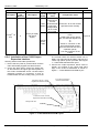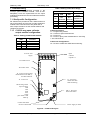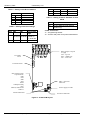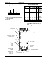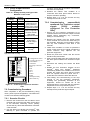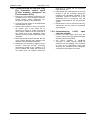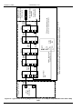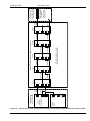
1
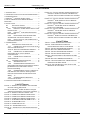
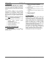
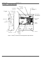
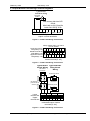
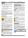
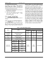
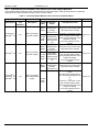
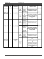
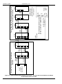
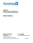
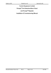
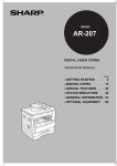
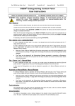
Written by: RKP Checked by: AJC Approved by JBJ Control Equipment Limited Precepten Output Expansion Module Installation & Commissioning Manual Doc Number: Prec en Output exp mod installation & commissioning Rev: 2 Page 1 of 23 23/12/09 Written by: RKP Checked by: AJC List of Contents 1. INTRODUCTION ........................................................... 3 2. OVERVIEW OF INSTALLATION AND COMMISSIONING .. 3 3. POWER SUPPLIES ...................................................... 3 EN 4. PRECEPT – INTERNAL PANEL VIEWS ...................... 4 5. OUTPUT MODULE FIELD WIRING/TERMINAL DIAGRAMS....................................................................... 7 6. INSTALLATION ............................................................. 8 6.1 ELECTRICAL SAFETY .................................. 8 6.2 INSTALLATION INSTRUCTIONS..................... 9 EN 6.2.1 PRECEPT 16 EXP PANEL INSTALLATION INSTRUCTIONS ........................................................ 9 EN 6.2.2 PRECEPT 4 AND 5 EXP EXPANSION ENCLOSURES .......................................................... 9 6.2.3 INTERCONNECTIONS BETWEEN FIRE ALARM PANEL AND OUTPUT MODULES ............... 10 6.2.4 INSTALLATION OF THE C1630 OUTPUT EXPANSION INTERFACE ........................................ 12 7. COMMISSIONING ....................................................... 13 7.1 SITE-SPECIFIC CONFIGURATION. ............. 13 7.1.1 C1633 8-WAY OPEN COLLECTOR OUTPUT MODULE CONFIGURATION. .................................... 13 TABLE 5 - SETTING C1634 BOARD ADDRESS ..... 14 7.1.2 C1635 8-WAY ALARM/POWERED – MONITORED RELAY OUTPUT MODULE CONFIGURATION. .................................................. 15 7.1.3 C1630 OUTPUT INTERFACE CONFIGURATION ................................................... 16 7.2 COMMISSIONING PROCEDURE.................. 16 7.2.1 SOUNDER CIRCUITS ............................. 16 7.2.2 COMMISSIONING POWERED/FAULT MONITORED FIRE PROTECTION CONTROL SIGNALS [C1635 MODULES CONFIGURED AS FIRE PROTECTION O/PS] .............................................. 16 7.2.3 COMMISSIONING THE VOLT-FREE RELAY FIRE PROTECTION CONTROL SIGNAL [C1634 MODULES CONFIGURED AS FIRE PROTECTION O/PS] 17 7.2.4 COMMISSIONING C1633 OPEN COLLECTOR OUTPUTS ........................................... 17 8. CONSTRUCTION PRODUCTS DIRECTIVE .................. 23 FIGURE 12 – TYPICAL INTERNAL WIRING DIAGRAM FOR EN PRECEPT 8/16 WITH INTERNAL O/P MODULES AND EXP 4 OUTPUT MODULE PANEL WITH NO PSU ...............................................................................18 FIGURE 13 – TYPICAL INTERNAL WIRING DIAGRAM FOR EN PRECEPT 8/16 AND EXP 4 OUTPUT MODULE PANEL WITH NO PSU ............................................19 FIGURE 14 – TYPICAL INTERNAL WIRING DIAGRAM FOR EN PRECEPT 32 AND EXP 5 OUTPUT MODULE PANEL WITH 5 AMP PSU ......................................20 FIGURE 15 – TYPICAL INTERNAL WIRING DIAGRAM FOR EN PRECEPT 32 AND EXP 5 OUTPUT MODULE PANEL WITH NO PSU ............................................21 FIGURE 16 – TYPICAL INTERNAL WIRING DIAGRAM FOR EN PRECEPT 8/16 WITH INTERNAL O/P MODULES AND EXP 4 OUTPUT MODULE PANEL WITH PSU ..22 List of Tables TABLE 1 – PANEL SPARES BAG CONTENTS ...................9 TABLE 2 - FIRE PANEL/OUTPUT MODULE INTERCONNECTION INSTALLATION W ORK ............10 TABLE 3 - SETTING C1633 BOARD ADDRESS..............13 TABLE 4- SETTING C1633 ZONE RANGE .....................13 TABLE 5 - SETTING C1634 BOARD ADDRESS..............14 TABLE 6 - SETTING C1634 ZONE RANGE ....................14 TABLE 7 – SETTING C1634 TO STANDARD OR VDR MODE.....................................................................14 TABLE 8- SETTING C1635 BOARD ADDRESS...............15 TABLE 9 – SETTING C1635 TYPE, GENERAL/ZONAL RESPONSE AND ZONE RANGE...............................15 TABLE 10 – SETTING QUANTITY AND TYPE OF O/P MODULES ON THE C1630 .....................................16 List Of Figures FIGURE 1 – PRECEPT 16 INTERNAL VIEW SHOWING OPTIONAL SINGLE O/P BOARD................................ 4 EN FIGURE 2 - PRECEPT 16 EXP INTERNAL VIEW [32 ZONE ENCLOSURE] WITH TWO OUTPUT BOARDS ... 5 EN FIGURE 3 – PRECEPT EXP 5 INTERNAL VIEW .............. 6 FIGURE 4 - C1633 FIELD W IRING CONNECTIONS ......... 7 FIGURE 5 - C1634 FIELD W IRING CONNECTIONS ......... 7 FIGURE 6 - C1635 FIELD W IRING CONNECTIONS ......... 7 FIGURE 7 – C1627 MOTHERBOARD PCB LAYOUT ..... 12 FIGURE 8 – C1633 PCB LAYOUT ................................ 13 FIGURE 9 - C1634 PCB LAYOUT ................................. 14 FIGURE 10 – C1635 PCB LAYOUT.............................. 15 FIGURE 11 – C1630 OUTPUT EXPANSION INTERFACE PCB ...................................................................... 16 EN Doc Number: Prec en Output exp mod installation & commissioning Rev: 2 Page 2 of 23 23/12/09 Written by: RKP 1. Introduction Checked by: AJC en Thank you for purchasing the Precept conventional fire detection and alarm equipment. en The Precept range of panels have been designed to meet the requirements of BSEN 54 Parts 2 & 4 and will provide the user with many years of reliable service. This document contains all the information necessary for the installation, commissioning and en maintenance of the Precept range of output expansion panels. Installation and commissioning en details for Precept fire detection and alarm panels en are covered in the Precept manuals mentioned below. NOTE: It is important to read this manual fully before commencing installation. The following supporting documentation is also available: en Precept Output Expansion System Application Guide en Precept Sales Literature en Precept Panel Application Guide en Precept User Manual Wiring Recommendations 2. Overview of Installation and Commissioning This section lists the steps that are taken in en installing and commissioning a Precept output expansion system. 1. Install all field wiring and equipment Refer to the Installation Guidelines in section 6.2 below Refer to the field device installation manuals 2. Install the panel Refer to the installation instructions in section 6.2 below Do not connect the field equipment at this stage. 3. Commission the panel Refer to section 6. 3. Power Supplies en The Precept 8 fire alarm panel utilises the standard 230Vac 3A PSU fitted to the C1627 en motherboard. The Precept 16 Exp fire alarm panel uses the C1652 230Vac 5A PSU mounted on the internal chassis beneath the motherboard/output en modules. Precept Exp 4 and 5 output expansion panels are supplied with or without a C1652 230Vac 5A PSU depending on the output load requirement. When fitted, the PSU is located on the chassis underneath the output modules. For all panels, the output voltage is adjustable from 25V to 28.2V via a small trimmer potentiometer on the PCB. As the output voltage is factory set however, adjustment should not be necessary. en Details of the PSUs can be found in the Precept manuals [Prec en inst.doc, Prec en app.doc] Doc Number: Prec en Output exp mod installation & commissioning Rev: 2 Page 3 of 23 23/12/09 Written by: RKP Checked by: AJC 4. Precepten – Internal Panel Views 3 x enclosure fixing holes Removable chassis Cable clip for incoming mains cable Mains warning/primary earth label Secondary earth bar for cable screens TB15 TB16 AUX D.C. 24V 0V INPUTS TB17 TB18 OUTPUTS TB19 REPEATER TB20 TB21 FS6 + 11 - + - + - + 12 13 14 ZONE CIRCUITS + 15 - + 16 - O/+ P C/FAULT ROUTING C/+ P O/FIRE ROUTING J8 J7 N/C P RESET Removable chassis N/O J17 N/C J20 Motherboard C/+ P O/FIRE PROTECTION I/O EXPANSION - J17 10 J16 J15 J14 + J12 J11 J10 - 9 J6 + RL8 TB14 RL7 ALARM CIRCUITS 2 3 4 + - + - + - RL6 - RL5 1 RL4 + TB12 B + 8- TB10 A + 7- TB9 RL3 TB8 RL2 TB7 RL1 TB6 RESET N/O ZONE CIRCUITS + 4- + 5- + 6- + 3- TB5 SCN + 2- TB4 BUZ. ACTIVE + 1- TB3 DIS. 4 EVAC. 3 TB2 RST. 2 EVAC 1 SIL. ZONE OUTPUTS TB1 CLASS CHANGE Mains terminal block and primary earth connection 4 5 ZONE EXPANSION R1 R2 CEL C1631 ISSUE 0 R0 3 3 J20 7 + C88 6 LED 1 LOG 2 2 S/C 0 S/C 1 LED 0 SW1 1 1 F/P 0 F/P 1 C1630 ISSUE 0 COM SW1 BUZ1 C78 + Mains transformer HS2 + C78 BUZ1 U27 HS1 TB23 C84 BR1 J1 + ~ ~ BR1 U1 U13 DISPLAY U28 R296A VR1 OUTPUT J1 R296B R297B VR1 4 5 6 CONFIG M/S ZONES 6 7 7 PULSE NON-ALARM ZONES 8 8 SILENT ZONE TEST 9 10 2 STAGE DELAY 9 10 LATCHED FAULTS ALARMS ON EVAC ONLY I1 L2 8 J18B OUTPUT OK C90 ZONAL ALARMS CONFIG DELAY ZONES CONFIG DELAY O/PS R297B D52 + C90 3 CONFIG NON-LATCH ZONES 5 2 DELAY/ MINUTES 4 4 2 3 1 L3 BAT/CHG FAULT L4 INTERNAL FAULT L5 MAINS FAULT D51 BUZZER DISABLE TB11 FS1 BATTERY FUSE - BATT TB13 + THERM C1630 O/P expansion interface board Motherboard Figure 1 – Precept SILENCE BEFORE RESET CONFIG I/S ZONES C1627 ISSUE 1 Batteries 1 DELAY ALARM SIL & RESET DELAY ON AUTO L1 ORIGN1 INHIBIT F/P ON NLZ 2 CONFIG ENABLED SW2 1 SW1 en Output Module Batteries 16 internal view showing optional single O/P board Doc Number: Prec en Output exp mod installation & commissioning Rev: 2 Page 4 of 23 23/12/09 Written by: RKP Checked by: AJC Cable clip for incoming mains cable 3x enclosure fixing holes Secondary earth bars for cable screens Mains warning/primary earth label TB6 TB7 TB14 TB15 TB16 O/C TB21 OP8 OP7 OP6 OP5 OP4 OP3 OP2 OP1 OP8 REPEATER TB20 OP7 OUTPUTS TB19 OP6 INPUTS TB18 OP5 AUX D.C. 24V 0V TB17 OP4 ALARM CIRCUITS 2 3 4 + - + - + - OP3 - OP2 1 OP1 + TB12 TB10 B + 8- TB9 A + 7- TB8 RESET N/O ZONE CIRCUITS + 4- + 5- + 6- + 3- TB5 SCN + 2- TB4 EVAC. + 1- TB3 BUZ. ACTIVE 4 DIS. 3 TB2 RST. 2 EVAC 1 SIL. ZONE OUTPUTS TB1 CLASS CHANGE Mains terminal block and primary earth connection O/C FS6 11 - + - + - + 12 13 14 ZONE CIRCUITS - + 15 - + 16 - O/+ P C/FAULT ROUTING C/+ P O/FIRE ROUTING - + - J8 J7 + +24V N/C P RESET +24V Removable chassis J17 5 6 7 LOG R0 R1 R2 J20 + C88 4 LED 1 ZONE EXPANSION 3 S/C 1 LED 0 SW1 3 2 S/C 0 2 1 F/P 0 F/P 1 CEL C1631 ISSUE 0 SW1 1 LOOP INTERFACE BOARD C1630 ISSUE 0 J20 LOOP IN LOOP OUT C/+ P O/FIRE PROTECTION J17 + J16 J15 J14 10 - I/O EXPANSION 9 + J12 J11 J10 - J6 + HS2 + BUZ1 + C78 C78 BUZ1 U27 HS1 TB23 C84 BR1 J1 + ~ ~ BR1 U13 DISPLAY U28 R296A VR1 OUTPUT J1 R296B R297B VR1 SW2 1 2 2 3 3 4 5 5 6 6 4 CONFIG DELAY ZONES 7 8 CONFIG DELAY O/PS 8 SILENT ZONE TEST 9 10 2 STAGE DELAY 9 10 7 ORIGN1 2 DELAY/ MINUTES 4 8 BUZZER DISABLE C1627 ISSUE 1 ALARMS ON EVAC ONLY + 1 ZONAL ALARMS R297B D52 SILENCE BEFORE RESET CONFIG NON-LATCH ZONES CONFIG I/S ZONES CONFIG M/S ZONES L1 C90 INHIBIT F/P ON NLZ DELAY ALARM SIL & RESET DELAY ON AUTO 1 SW1 CONFIG ENABLED I1 L2 OUTPUT OK L3 BAT/CHG FAULT L4 INTERNAL FAULT L5 MAINS FAULT C90 PULSE NON-ALARM ZONES TB11 LATCHED FAULTS FS1 BATTERY FUSE - BATT TB13 + J18B D51 THERM 2 x output modules Motherboard with 5 Amp PSU with transformer underneath Figure 2 - Precept C1630 O/P expansion interface board en Batteries 16 Exp internal view [32 zone enclosure] with two Output boards Doc Number: Prec en Output exp mod installation & commissioning Rev: 2 Page 5 of 23 23/12/09 Written by: RKP Secondary earth bars for cable screens Checked by: AJC Mains warning/primary earth label Cable clip for incoming mains cable 3 x enclosure fixing holes Mains terminal block and primary earth connection Removable chassis Batteries PSU and transformer under O/P boards Space for 5 x output modules Figure 3 – Precept en Exp 5 internal view Doc Number: Prec en Output exp mod installation & commissioning Rev: 2 Page 6 of 23 23/12/09 Written by: RKP Checked by: AJC 5. Output Module Field Wiring/Terminal Diagrams Typical LED indication wiring 2k2 0.5W resistor Max current sink into O/P: 60mA Max load on 24 V [total for both +24V O/Ps]: 0.5A +24 +24 OP1 OP2 OP3 OP4 OP5 OP6 OP7 OP8 V V TB1 TB2 TB3 TB4 TB5 C1633 Open collector output module terminals Figure 4 - C1633 Field Wiring Connections Relay contact rating: 1A at 30 V Do not exceed Lower terminal tier N/O [Relays 1-8] Middle terminal tier Pole [Relays 1-8] Upper terminal tier N/C [Relays 1-8] OP1 OP2 OP3 OP4 OP5 OP6 OP7 OP8 TB1 TB2 TB3 TB4 [1] [2] [3] [4] [5] [6] [7] [8] [1] [2] [3] [4] [7] [8] [5] [6] C1634 Volt free relay output module terminals [3- tier] Figure 5 - C1634 Field Wiring Connections Typical Alarm Typical Remote Circuit Wiring Relay Circuit 3k9 resistor Wiring end-of-line Suppression diode I/P polarised [All sounder devices] Lower terminal tier Upper terminal tier + - + 3k9 resistor end-of-line + - + - OP1 - + OP5 Polarising diode OP2 + - OP6 OP3 - + OP7 OP4 + - OP8 - + - + - + C1635 powered/fault monitored output module terminals [2- tier] + Figure 6 - C1635 Field Wiring Connections Doc Number: Prec en Output exp mod installation & commissioning Rev: 2 Page 7 of 23 23/12/09 Written by: RKP Checked by: AJC 6. Installation The panel must be installed by suitably qualified engineers familiar with the installation of fire detection systems. In addition, it is recommended to refer to the following information: Current edition of the IEE wiring regulations. Current edition of BS5839-1 or the installation standards for the relevant country. Any specific site requirements. Any field device installation instructions. Any data sheet provided for the installation of Intrinsically Safe devices. Notes: The rating plate, containing essential electrical information is located inside the panel on the inside face of the door. Any mains supply cable should be a minimum 2 of 1mm copper protected by a 5A fuse and must include an appropriate lockable double pole disconnect device as part of the building installation. This device must have a minimum contact gap of 3mm. 6.1 Electrical Safety WARNING: Read this section completely before commencing installation. Prior to commencing installation of the panel, ensure that adequate precautions are taken to prevent damage to the sensitive electronic components on the PCBs due to electrostatic discharge. You should discharge any static electricity you may have accumulated by touching a convenient earthed object such as an unpainted copper radiator pipe. You should repeat the process at regular intervals during the installation process, especially if you are required to walk over carpets. The panel must be located in a clean, dry position, which is not subject to shock or vibration and at least 2 metres away from pager systems or any other radio transmitting equipment. The operating temperature range is 5ºC to 40ºC; maximum humidity is 95%. en en Precept Exp 4 and Precept Exp 5 Output Expansion panels must be located immediately adjacent to the fire alarm panel. IMPORTANT NOTES ON BATTERIES [when fitted]: DANGER: Batteries are electrically live at all times, take great care never to short circuit the battery terminals. WARNING: Batteries are often heavy; take great care when lifting and transporting batteries. For weights above 24 kilos, lifting aids should be used. DANGER: Do NOT attempt to remove the battery lid or tamper with the internal workings of the battery. Electrolyte is a Approved by JBJ highly corrosive substance, and presents significant danger to yourself and to anything else it touches. In case of accidental skin or eye contact, flush the affected area with plenty of clean, fresh water and seek immediate medical attention. Valve Regulated Lead Acid (VRLA) batteries are “low maintenance”, requiring no electrolyte topup or measurement of specific gravity. WARNING: Only clean the battery case with a cloth that has been soaked or dampened with distilled water. Do not use organic solvents (such as petrol, paint thinner, benzene or mineral spirits) or other materials that can substantially weaken the case. Do not use a dry cloth as this will generate static electricity, which in turn may lead to an explosion. WARNING: Avoid operating temperatures outside the range of -15C/5F to +50°C/122°F for float/standby applications. The recommended normal operating temperature is 20°C. HIGH TEMPERATURE will reduce battery service life. In extreme cases this can cause Thermal Runaway, resulting in high oxygen/hydrogen gas production and battery swelling. Batteries are irrecoverable from this condition and should be replaced. LOW TEMPERATURE will prolong battery life but reduce output capacity. DANGER: Do not incinerate batteries. If placed in a fire, the batteries may rupture, with the potential to release hazardous gases and electrolyte. VRLA batteries contain substances harmful to the environment. Exhausted batteries must be recycled. Return them to the battery manufacturer or take them to your Council waste disposal site for appropriate disposal. ELECTRICAL SAFETY: The volt-free relay contacts provided within the panel must not be used to directly switch any voltage that exceeds 50VAC or 75VDC. (Please also refer to relay rating data). Equipment requiring a 230V AC supply. [See Rating Plate inside equipment. See also 1. above.] All installation work should be carried out in accordance with the recommendations of BS5839 Part 1 and the current edition of the IEE regulations by suitably qualified and trained personnel. Doc Number: Prec en Output exp mod installation & commissioning THIS PANEL MUST BE EARTHED Rev: 2 Page 8 of 23 23/12/09 Written by: RKP Checked by: AJC 6.2 Installation Instructions en The flexibility of the Precept Output Expansion System allows many different combinations of enclosure/PSU/output modules. As such these instructions cannot cover every single variation and so provide general instructions only. 1. Carefully remove the panel from the packing and lay the panel on a flat surface. 2. Open the door of the panel. 3. Locate the spares bag[s] and check contents, which should comply with Table 1 – Panel Spares Bag Contents. 6.2.1 Precepten 16 Exp Panel Installation Instructions See Precept en panel installation manual – [Prec en inst.doc] 6.2.2 Precepten 4 and 5 Exp Expansion Enclosures Matching 25mm knock-outs are provided on the en right hand face of the Precept 8/16 fire alarm panel enclosure and the left hand face of the en Precept 4 Exp output expansion enclosure to allow the panels to be coupled together with the expansion panel on the right. A similar arrangement en is provided for connecting Precept 32 control en panels to the Precept 5 Expansion enclosure. Mount and fix the fire alarm panel enclosure in accordance with the instructions provided in the en Precept panel installation manual – [Prec en inst]. After fitting the fire alarm control panel, remove the chassis from the output expansion panel generally en as described in the Precept panel installation manual – [Prec en inst], carefully remove the 25mm knock-outs in the adjoining faces of both fire panel and expansion enclosures [by knocking out from the inside of the enclosure to the outside] and fit a 25mm coupler to one panel. Offer up the expansion box, aligning the two enclosures via the coupler then mark. Fix the expansion enclosure to the wall en as described in the Precept panel installation manual – [Prec en inst]. Tighten up the coupler. Continue to install in accordance with the relevant en guidelines provided in the Precept panel installation manual – Prec en inst] as appropriate to the output expansion module system provided. Table 1 – Panel Spares Bag Contents Spares Bag Panel en Precept 8/16 panel with optional O/P module en Precept 8/16 Exp Exp 4 or 5 [no PSU] en See Precept installation and commissioning manual. [Prec en inst] None required None required 8 x 3k9 0.25W None required None required 8 x 3k9 0.25W None required None required 8 x 3k9 0.25W None required None required 8 x 3k9 0.25W en See Precept installation and commissioning manual. [Prec en inst] Engineer’s door keys. Key Ref.: 801 [Flat key type] T3.15AH250V Mains Fuse: 20mm Battery Fuse: Exp 4 or 5 [C1652 PSU] Expansion Modules [as fitted] C1635 C1633 C1634 [1 x bag/module] Panel Engineer’s door keys: F6.3AL250V 20mm Key Ref.: 801 [Flat key type] Positive battery lead: Red Negative battery lead: Black Battery coupling lead: Blue Doc Number: Prec en Output exp mod installation & commissioning Rev: 2 Page 9 of 23 23/12/09 Written by: RKP Checked by: AJC 6.2.3 Interconnections between Fire Alarm Panel and Output Modules The standard output expansion panel combinations are listed below [see Table 2] along with their respective requirements for interconnection for the 3 types of O/P modules. Table 2 - Fire Panel/Output Module Interconnection Installation Work Fire Alarm Control Panel Expansion Panel Internal Internal Description O/P Description Cable Modules en No Exp 4 [or Exp5] no power supply. en 32 No Exp 4 [or Exp5] no power supply. Fire panel Aux DC motherboard power [C1627] power cable out connector J24 “Power in” connector on the first C1633/C1635 module [from the left hand side of the expansion panel]. J4 on the C1633/J3 on the C1635. Fire panel motherboard [C1627] connector J17. Connector J2 on O/P module 1[left hand most module] Fire panel Aux DC motherboard power [C1627] power cable out connector J24 “Power in” connector on the first C1633/C1635 module [from the left hand side of the expansion panel]. J4 on the C1633/J3 on the C1635. Fire panel motherboard [C1627] connector J17. Connector J2 on O/P module 1[left hand most module] Data Ribbon en Precept 8 en Precept 16 en Precept 32 No In Expansion Panel Connector J2 on O/P module 1[left hand most module] Data Ribbon Precept In Precept Panel Exp 4 [or Exp5] with C1652 power supply. Aux DC power cable Doc Number: Prec en Output exp mod installation & commissioning Schematic en Fire panel motherboard [C1627] connector J17. Data Ribbon Precept 8 en Precept 16 Internal Connections Factory fitted. From: C1652 power supply board 28V, 0V and fault signals from J1. To: “Power in” connector on the first C1633/C1635 module [from the left hand side of the expansion panel]. J4 on the C1633/J3 on the C1635. Figure 13 Figure 15 Figure 14 Rev: 2 Page 10 of 23 23/12/09 Written by: RKP Checked by: AJC Fire Alarm Control Panel Expansion Panel Internal Internal Description O/P Description Cable Modules Data Ribbon en Precept 8 with a single O/P module 1 Exp 4 [or Exp5] no power supply. Aux DC power cable Data Ribbon en Precept 16 Exp 2 Exp 4 [or Exp5] no power supply. Aux DC power cable Data Ribbon en Precept 8 with a single O/P module 1 Internal Connections In Precept Panel Schematic en Data out connector on the O/P module. J6 on C1633 and C1635 “Power out” connector on the C1633/C1635 module. J3 on the C1633/J5 on the C1635. Data out connector on the last C1633/C1635 [right-handmost] module . J6 on C1633 and C1635. “Power out” connector on the last C1633/C1635 [right-handmost] module J3 on the C1633/J5 on the C1635. Data out connector on the O/P module. J6 on C1633 and C1635 Exp 4 [or Exp5] with power supply. Aux DC power cable Doc Number: Prec en Output exp mod installation & commissioning In Expansion Panel Connector J2 on O/P module 1[left hand most module] “Power in” connector on the first C1633/C1635 module [from the left hand side of the expansion panel]. J4 on the C1633/J3 on the C1635. Figure 12 [showing 2 x O/P modules] Connector J2 on O/P module 1[left hand most module]. Figure 12 “Power in” connector on the first C1633/C1635 module [from the left hand side of the expansion panel]. J4 on the C1633/J3 on the C1635. Connector J2 on O/P module 1[left hand most module] Factory fitted. From: C1652 power supply board 28V, 0V and fault signals from J1. To: “Power in” connector on the first C1633/C1635 module [from the left hand side of the expansion panel]. J4 on the C1633/J3 on the C1635. Figure 16 Rev: 2 Page 11 of 23 23/12/09 Written by: RKP Checked by: AJC Fire Alarm Control Panel Expansion Panel Internal Internal Description O/P Description Cable Modules Data Ribbon en Precept 16 Exp 2 Internal Connections In Precept Panel Data out connector on the last C1633/C1635 [right-handmost] module J6 on C1633 and C1635. Aux DC power cable 6.2.4 Installation of the C1630 Output Expansion Interface Warning: Observe anti-static precautions 1. Ensure that the panel is powered down and the main and standby supplies are disconnected. 2. On the fire alarm panel, remove the jumper link at J23 located in the upper right hand quarter of the C1627 motherboard and fit a C1630 output expansion interface to connectors J4 and J5 located below the fault routing relay. [J23 must In Expansion Panel Connector J2 on O/P module 1[left hand most module]. Factory fitted. From: C1652 power supply board 28V, 0V and fault signals from J1. To: “Power in” connector on the first C1633/C1635 module [from the left hand side of the expansion panel]. J4 on the C1633/J3 on the C1635. Exp 4 [or Exp5] with power supply. Schematic en Figure 16 be removed before the interface board can be fitted]. The board should be held in place by the 12mm high plastic spacer provided. See Figure 7 – C1627 Motherboard PCB Layout. 3. Connect the output expansion ribbon cable to header J17 located on the centre right hand edge of the C1627 motherboard as shown in Figure 7 – C1627 Motherboard PCB Layout. Connector J5 for C1630 Expansion Interface PCB J17 output expansion ribbon cable header Connector J4 for C1630 Expansion Interface PCB Jumper link J21 Figure 7 – C1627 Motherboard PCB Layout Doc Number: Prec en Output exp mod installation & commissioning Rev: 2 Page 12 of 23 23/12/09 Written by: RKP Checked by: AJC Table 4- Setting C1633 Zone Range 7. Commissioning The commissioning guidelines provided in the en Precept panel installation manual – Prec en inst. adequately cover the requirements for the output modules and should be read and understood before proceeding. 7.1 Site-Specific Configuration. DIL switches are provided on the C1630 interface to set up the quantity of each type of output expansion module to be connected to the fire panel and on each output module to set the module address and configure its function. 7.1.1 C1633 8-way open collector output module configuration. Table 3 - Setting C1633 Board Address SW1 AD0 AD1 Off Off On Off Off On On On Function Board Address 1 2 3 4 SW1 Function O/P 1-8 zone Zonal ZN0 ZN1 range All O/Ps Not Not Off operate on functional functional any zonal fire On Off Off Z 1-8 On On Off Z9-16 On Off On Z17- 24 On On On Z25 -32 C1633 Connectors: J1 – Programming header. J2 – Comms to panel motherboard. J3 – Power out. J4 – Power in [from panel motherboard or aux PSU] + Aux PSU fault I/P. C1633 Link Configuration: J5 – Fit link to enable Aux PSU fault monitoring. Open collector outputs 1-8 24 V DC Aux supply J2 Comms in/out J6 Comms out/in J4 – Power in [from panel motherboard or aux PSU] + Aux PSU fault I/P. J5 – Fit link to enable Aux PSU fault monitoring. J3 – Power out. SW1Config switch Top to bottom: AD0 AD1 ZN0 ZN1 Zonal [See Table 3 and Table 4] SW 2 – Processor fault reset button Comms fault LED Processor fault LED Power supply on LED Figure 8 – C1633 PCB Layout Doc Number: Prec en Output exp mod installation & commissioning Rev: 2 Page 13 of 23 23/12/09 Written by: RKP Checked by: AJC Table 5 - Setting C1634 Board Address SW1 AD0 Off On Off On AD1 Off Off On On Function Board Address 1 2 3 4 Table 6 - Setting C1634 Zone Range SW1 Zonal ZN0 ZN1 Off On Function O/P 1-8 zone range Not Not All O/Ps functional functional operate on any zonal fire Off Off Z 1-8 On On On On Off On Off On On Z9-16 Z17- 24 Z25 -32 Table 7 – Setting C1634 to Standard or VDR Mode SW1 Off On Function Fire Protection module Voyage Data Recorder [Marine Panels only] C1634 Connectors: J1 – Programming header. J2 – Comms and power from panel motherboard. Relay outputs 1-8 [left to right] N/O - top row Pole – middle row N/C – lower row. J2 Comms in/out J3 Comms out/in SW1 Config switch Top to bottom: AD0 AD1 ZN0 ZN1 Zonal VDR [Not used] [See Table 5, Table 6 and Table 7] SW2 – Processor fault reset Power supply on LED Comms fault LED Processor fault LED Figure 9 - C1634 PCB Layout Doc Number: Prec en Output exp mod installation & commissioning Rev: 2 Page 14 of 23 23/12/09 Written by: RKP Checked by: AJC 7.1.2 C1635 8-way alarm/powered – monitored relay output module configuration. Table 8- Setting C1635 Board Address SW1 AD0 AD1 Off Off On Off Off On On On Function Board Address 1 2 3 4 C1635 Connectors: J1 – Programming header. J2 – Comms to panel motherboard. J3 – Power in [from panel motherboard or aux PSU] + Aux PSU fault I/P. J5 – Power out. C1635 Link Configuration: J4 – Fit link to enable Aux PSU fault monitoring. Table 9 – Setting C1635 Type, General/Zonal Response and Zone range Panel SW1/6 SW1 SW1 SW1 Mode Board [FP] Zonal ZN0 ZN1 SW2/6 O/P 1-8 zone range General alarm (all O/Ps operate on any fire) Off SNDR Off N/A N/A N/A Off SNDR On On Off Off Off SNDR On On On Off Z9-16 Off SNDR On On Off On Z17- 24 Off SNDR On On On On Z1-8 Z25 -32 All O/Ps On FP N/A Off N/A N/A operate on any fire On FP N/A On Off Off Z1-8 On FP N/A On On Off Z9-16 On FP N/A On Off On Z17- 24 On FP N/A On On On Z25 -32 Notes: SNDR = Sounders, FP = Fire Protection When panel SW 2/6 is on: If panel SW2-7 is off, non-alarm zones are silent. If panel SW2-7 is on, non-alarm zones pulse en [See Precept panel manuals] J2 Comms in/out Outputs 1-8 [1-4 top row, 5-8 lower row, left to right] J6 Comms out/in J3 – Power in [from panel motherboard or aux PSU] + Aux PSU fault I/P. J5 – Power out. J4 – Fit link to enable Aux PSU fault monitoring. SW1Config switch Top to bottom: AD0 AD1 ZN0 ZN1 Zonal FP See Table 8 and Table 9 Output fault LEDs for O/Ps 1 to 8 [left to right] SW 2 Reset processor Power supply on LED Processor fault LED Comms fault LED Figure 10 – C1635 PCB Layout Doc Number: Prec en Output exp mod installation & commissioning Rev: 2 Page 15 of 23 23/12/09 Written by: RKP Checked by: AJC 7.1.3 C1630 Output Interface Configuration Table 10 – Setting Quantity and Type of O/P Modules on the C1630 DIL Switch Number Type of board setting of boards F/P0 F/P1 C1634 or C1635 Off Off 0 configured to FP On Off 1 [Fire protection Output]. See C1635 Off On 2 configuration details. On On 4 S/C0 S/C1 C1635 configured as Off Off 0 sounder module. On Off 1 See C1635 Off On 2 configuration details. On On 4 LED0 LED1 Off Off 0 C1633 open On Off 1 collector output module Off On 2 On On 4 VDR Not used on Off 0 en Precept On 1 [Note: Select switch to left hand side for OFF and right-hand side for ON] Configuration switch to set qty and type of O/P modules connected From top to bottom: F/P0 F/P1 S/C0 S/C1 LED0 LED1 VDR [Not used] [See Table 10] Figure 11 – C1630 output expansion interface PCB 7.2 Commissioning Procedure sounders. Check that all sounders connected to the alarm circuit operate. 3. Deselect the Alarms Test condition or if “Evacuate” was used, press silence alarms to stop the sounders operating. 4. Repeat steps 1 to 3 for the second and any subsequent sounder circuits. 7.2.2 Commissioning powered/fault monitored Fire Protection control signals [C1635 modules configured as Fire Protection O/Ps] 1. Ensure any fire protection equipment to be controlled via the Fire Protection output is locked off/safe before attempting any connection, testing or commissioning. 2. Remove the resistor from the C1635 output circuit terminal and connect the field wiring to the terminals, observing correct polarity. Check that any fault indications clear after a few seconds. 3. Initiate a fire condition on a zone to operate the output. Check that the fire signal operates the remote interface relay adjacent the fire protection equipment. 4. Reset the panel and confirm that the remote interface relay deactivates. 5. Open-circuit the field wiring and confirm that the fire alarm panel indicates Fire Protection output fault. 6. Reconnect the cabling and confirm the faults clear. 7. Disable the Fire Protection Outputs via the en en Precept panel [see Precept Operating Instructions]. Initiate a fire condition on a zone to operate the output and check that the output does not operate. Reset the panel and re – enable the Fire Protection O/Ps after the test. 8. Final testing and commissioning of the loop through to the fire protection equipment, including test [simulated] activation of the equipment, should be carried out at the appropriate time in conjunction with the engineer responsible for the fire protection system. 9. Repeat steps 1 to 7 for the second and any subsequent fire protection signal outputs. After completion of the pre-commissioning wiring check, power-up and configuration, commission the circuits in line with the following guide. 7.2.1 Sounder Circuits 1. Remove the resistor from the first alarm circuit terminal and connect the first alarm circuit wiring to the terminals, observing correct polarity. Check that any alarm fault indications clear after a few seconds. en 2. Use the Alarm Test facility [see Precept User Manual] or press Evacuate to operate the Doc Number: Prec en Output exp mod installation & commissioning Rev: 2 Page 16 of 23 23/12/09 Written by: RKP Checked by: AJC 7.2.3 Commissioning the volt-free relay Fire Protection control signal [C1634 modules configured as Fire Protection O/Ps] 1. Ensure any fire protection equipment to be controlled via the Fire Protection output is locked off/safe before attempting any connection, testing or commissioning. 2. Connect the field wiring to the appropriate terminals [N/O, P, N/C] 3. Initiate a fire condition on a zone to operate the output. Use a test meter set to continuity or Ohms to confirm the correct relay contact condition can be measured at the remote end of the installation wiring adjacent the fire protection equipment to be controlled. 4. Reset the fire alarm panel and with the test meter, confirm that the relay contacts have retruned to the deactivated condition. 5. Disable the Fire Protection Outputs via the en en Precept panel [see Precept Operating Instructions]. Initiate a fire condition on a zone to operate the output and check that the output does not operate. Reset the panel and re –enable the Fire Protection O/Ps after the test. 6. Final testing and commissioning of the loop through to the fire protection equipment, including test [simulated] activation of the equipment, should be carried out at the appropriate time in conjunction with the engineer responsible for the fire protection system. 7. Repeat steps 1 to 6 for the second and any subsequent volt free relay fire protection signal outputs. 7.2.4 Commissioning collector outputs C1633 open 1. Connect the field signal wires and the common return to the appropriate terminals observing the correct polarity. 2. The correct operation of equipment connected to these outputs should be verified in turn by initiating a fire condition on each of the appropriate zones and observing the operation of the equipment connected to the outputs in the field. Doc Number: Prec en Output exp mod installation & commissioning Rev: 2 Page 17 of 23 23/12/09 Doc Number: Prec en Output exp mod installation & commissioning Aux DC Data ribbon J3 J4 Aux DC J5 J3 J6 J2 J2 J6 C1635 J3 J2 C1634 C1633 1] Precept 8 with 1 off O/P module. 2] Precepten 8 with 2 off O/P modules. 3] Precepten 16 Exp with 2 off O/P modules. 4] Precepten 16 with Exp 4 [4 way O/P enclosure with max 4 O/P modules, with or without optional 5 Amp PSU and batteries]. 5] Precepten 32 with Exp 5 [5 way O/P enclosure with max 5 O/P modules, with or without optional 5 Amp PSU and batteries]. en Standard Panel Expansion Systems. J24 C1627 Precepten Motherboard J17 Data ribbon Precepten 8 or 16 Panel with internal Output Module[s] C1627 J17 Precepten Motherboard with 3Amp PSU J24 Data ribbon Precepten 8 or 16 fire panel with 1 x C1634 V/F Relay O/P module [using standard 3 Amp PSU] Aux DC Data ribbon C1633 Aux DC Data ribbon J5 J3 J6 J2 C1634 J3 J2 PSU load calculation must be carried out for each application Data ribbon J5 J3 J6 Data ribbon Note: All C1634 modules must be connected at the end of the sequence Precepten Exp 4 [4 way O/P expansion enclosure with 4 modules power from the Precept en panel C1635 Aux DC Data ribbon J2 C1635 J3 J2 C1634 PSU load calculation must be carried out for each application J5 J3 J6 J2 C1635 Note: To reduce the quantity of standard cable looms, any modules that are to be powered from the fire alarm panel need to be located in the left hand side of the output expansion enclosure. J3 J4 J6 J2 Aux DC Max current for O/P modules = 2.5A [156mA/output for 2 x modules] C1627 J17 Precepten Motherboard with 3Amp PSU J24 Data ribbon Precepten 8 or 16 with 2 x C1635 Sounder O/P module [using standard 3 Amp PSU] Written by: RKP Checked by: AJC Figure 12 – Typical internal wiring diagram for Precept 8/16 with internal O/P Modules and Exp 4 Output Module Panel with no PSU en Rev: 2 Page 18 of 23 23/12/09 Figure 13 – Typical internal wiring diagram for Precept PSU Aux DC en Doc Number: Prec en Output exp mod installation & commissioning 1] Precepten 8 with 1 off O/P module. 2] Precepten 8 with 2 off O/P modules. 3] Precepten 16 Exp with 2 off O/P modules. 4] Precepten 16 with Exp 4 [4 way O/P enclosure with max 4 O/P modules, with or without optional 5 Amp PSU and batteries]. 5] Precepten 32 with Exp 5 [5 way O/P enclosure with max 5 O/P modules, with or without optional 5 Amp PSU and batteries]. Standard Panel Expansion Systems. J24 J17 C1627 Precepten Motherboard Data ribbon Precepten 8 or 16 Panel [no internal Output Modules] J3 J4 J6 J2 C1633 J5 J3 J6 J3 J2 C1634 PSU load calculation must be carried out for each application Data ribbon Note: All C1634 modules must be connected at the end of the sequence Data ribbon J3 J2 C1634 Note: To reduce the quantity of standard cable looms, any modules that are to be powered from the fire alarm panel need to be located in the left hand side of the output expansion enclosure. Aux DC Data ribbon J2 C1635 Precepten Exp 4 [4 way O/P expansion enclosure with 4 modules powered from Precept en panel] Written by: RKP Checked by: AJC 8/16 and Exp 4 Output Module Panel with no Rev: 2 Page 19 of 23 23/12/09 J24 C1627 J17 Precepten Motherboard Data ribbon Precepten 8, 16 or 32 Figure 14 – Typical internal wiring diagram for Precept PSU en Doc Number: Prec en Output exp mod installation & commissioning Aux DC Data ribbon J5 J3 J6 J2 Aux DC Data ribbon J5 J3 J6 J2 0V 28V J1 PWR & Flt O/Ps J5 J3 J6 J2 C1635 C1652 5 Amp PSU Aux DC Data ribbon CFlt MFlt TB1 TB5 C1635 Aux DC, Mains Flt & Comm PSU Flt C1635 J5 J3 J6 J2 C1635 Aux DC Data ribbon Aux DC or use additional PSU Further expansion modules Note: All C1634 modules must be connected at the end of the sequence PSU load calculation must be carried out for each application Aux DC Data ribbon Note: To reduce the quantity of standard cable looms, any modules that are to be powered from the fire alarm panel need to be located in the left hand side of the output expansion enclosure. C1652 Power lead J3 J4 J6 J2 C1633 Precepten Exp 5 [5 way O/P expansion enclosure with 5 modules c/w 5 Amp PSU ] Written by: RKP Checked by: AJC 32 and Exp 5 Output Module Panel with 5 Amp Rev: 2 Page 20 of 23 23/12/09 Figure 15 – Typical internal wiring diagram for Precept C1652 5 Amp PSU en Doc Number: Prec en Output exp mod installation & commissioning J1 MFlt CFlt 28V 0V TB5 TB1 PWR & Flt O/Ps J19 J17 C1627 en Precept Motherboard J24 Precepten 32 with 5 Amp PSU Aux DC Data ribbon J3 J4 J6 J2 C1633 Aux DC Data ribbon J5 J3 J6 J2 C1635 J5 J3 J6 J2 Aux DC Data ribbon PSU load calculation must be carried out for each application Aux DC Data ribbon C1635 J5 J3 J6 J2 C1635 Precepten Exp 5 [5 way O/P expansion enclosure ] Aux DC Data ribbon J5 J3 J6 J2 C1635 Aux DC Data ribbon Further expansion modules Aux DC or use additional PSU Note: All C1634 modules must be connected at the end of the sequence Written by: RKP Checked by: AJC 32 and Exp 5 Output Module Panel with no PSU Rev: 2 Page 21 of 23 23/12/09 J24 J17 C1627 Precepten Motherboard Aux DC Data ribbon J3 J4 J6 Aux DC J5 J3 J6 J2 J2 Data ribbon C1635 C1633 Precepten 8 or 16 Panel with internal Output Module[s] Data ribbon Doc Number: Prec en Output exp mod installation & commissioning Aux DC Data ribbon J5 J3 J6 J2 C1635 Data ribbon J3 J2 Aux DC, Mains Flt & Comm PSU Flt Data J3 ribbon J2 C1634 0V 28V J1 PWR & Flt O/Ps TB1 TB5 CFlt MFlt C1652 5 Amp PSU Note: All C1634 modules must be connected at the end of the sequence C1634 PSU load calculation must be carried out for each application C1652 Power lead J3 J4 J6 J2 C1633 Precepten Exp 4 [4 way O/P expansion enclosure with 4 modules power from the Precept en panel Written by: RKP Checked by: AJC Figure 16 – Typical internal wiring diagram for Precept 8/16 with internal O/P Modules and Exp 4 Output Module Panel with PSU en Rev: 2 Page 22 of 23 23/12/09 Written by: RKP Checked by: AJC 8. Construction Products Directive 0086 Control Equipment Ltd Hillcrest Business Park Cinder Bank Dudley West Midlands DY2 9AP United Kingdom. 09 0086-CPD-555921 EN54-2 Control and indicating equipment for fire detection and fire alarm systems for buildings Provided options: Outputs to fire alarm devices. Outputs to Fire Protection Equipment – Output type B Test condition. Delays to Outputs EN54-4 Power supply equipment for fire detection and fire alarm systems for buildings Doc Number: Prec en Output exp mod installation & commissioning Rev: 2 Page 23 of 23 23/12/09