1
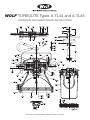
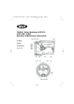
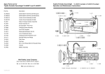
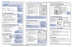
Wolf Turbolite Types A-TL44 and A-TL45
Parts List
Type A-TL44
Part No. Description
Type A-TL45
Part No.
BAYLIGHT
FLOODLIGHT
Type A-TL44
Part No. Description
Type A-TL45
Part No.
A-6
Screw for Air Inlet Plate (6)
A-6
A-105
Air Inlet Plate (3)
A-105
A-7
Screw for Stator (3)
A-7
A-106
‘O’ Ring Seal for Air Inlet Plate (3)
A-106
A-8
Wing Nut for Bridle Bolt (2)
A-8
A-109
Air Regulating Plate
A-109
A-11
Bridle Bolt for Wing Nut (2)
A-11
A-110
Piston Complete
A-110
A-13S
Bridle with Safety Hook
A-13S
A-113
Piston Spacer
A-113
A-16
Metal Washer
A-114
Spring for Piston (Silver Passivated)
A-114
A-18
Stainless Steel Fastening Screws
(3-TL44, 7-TL45)
A-115
Diaphragm
A-115
A-116
Lockscrew for Piston Chamber
A-116
A-19
Ball Glass
A-118S
Bulbholder complete
A-118S
A-21
Housing Cover
A-21
A-129
Bulb 24v. 250w. Tungsten Halogen
A-129
A-22K
Generator Housing Complete
A-22K
A-133
Connecting Tube
A-133
A-22
Generator Housing only
A-22
A-134
Overthrow Nut
A-134
A-22GEN
Generator Housing Assy
A-22GEN
Grooved Rubber Washer 15mm
A-139
Reflector Head
A-23
Glass Disc 15mm (toughened)
A-140
Reflector Head Assembly
A-23A
A-158
Grooved Rubber Washer
Lens Ring
A-24
A-159
A-28
Lock Nut for Regulating Screw
A-28
Bulb 24v. 250w. Tungsten Halogen
High Output
A-29
Regulating Screw
A-29
A-163
Lockscrew Ring/Guard
A-33
Air Filter Sieve
A-33
A-86
Wing Nut Retaining Clip (2)
A-34
Connecting Piece
A-34
A-36
Waved Spring Washer for Bearing (2)
A-36
A-37
Nut for Rotor Shaft
A-37
A-38
Turbine Wheel
A38
A-40
Ball Bearing with Race (2)
A-40
A-41
Rotor Shaft
A-41
A-52
Insulating Bush (2)
A-52
A-53
Screw for Stator Terminal (2)
A-53
A-54
Stator Winding
A-54
Reflector Matt
A-57M
A-18
Reflector Polished
A-57P
A-72
Lock Washer for Bridle (2)
A-72
A-74
Lock Screw for /Rfl.Hd./Guard
A-74
‘O’ Ring Seal for Reflector Head
A-77
A-80
Magnet
A-80
A-85
Rotor Assembly
A-85
A-87
Washer for Stator Terminal (2)
A-87
A-88
Nut for Stator Terminal (2)
A-88
A-98
Collar for Lockscrew
A-98
A-101
Washer for Rotor Shaft Nut
A-101
A-102
Rotor Spacer
A-102
WOLF SAFETY LAMP COMPANY
Saxon Road Works, Sheffield S8 0YA, England
Tel: +44 114 255 1051 Fax: +44 114 255 7988
E-mail: [email protected] Website: www.wolf-safety.co.uk
AL-92 Issue 4
MMD/??/5.11/??K
A-159
A-86
Tools and Accessories for use with Wolf Turbolite Lamps
Tools
A-68
Pair of Pressure Regulating Keys
A-68
A-146
Key for Nut No. A-37
A-146
A-170
Hexagon Key for A-18 (3/16 A/F)
A-170
A-171
Hexagon Key for A-74 (2.5m/m A/F)
A-171
Accessories
A-178
Lubricant 400 gram tube
A-178
A-179
Antistatic Hose 1⁄2" bore 18.3m. (60')
A-179
A-180
Antistatic Hose 1⁄2" bore 36.6m. (120')
A-180
A-181
Stainless Steel Hose Clips
A-181
A-184
Filter/Automatic Drain Unit (2 Lamps)
A-184
A-186
Ultra High Efficiency, Two Stage Filter/
Automatic Drain Unit – (2 Lamps)
A-186
A-300
Folding Tripod Stand
A-300
WOLF TURBOLITE Types A-TL44 and A-TL45
OPERATION AND MAINTENANCE INSTRUCTIONS
EXTERNAL FEATURES MAY CHANGE WITHOUT NOTICE
Wolf Turbolite Types A-TL44 and A-TL45
Operation and Maintenance Instructions
TYPE A-TL44:
Lockscrew Ring/Guard A-163 for Ball Glass is removed
from the Generator Housing in the same manner.
Introduction
The Wolf “Turbolites” are 250 Watt Tungsten Halogen
compressed air operated safety lamps. Type 44 is fitted
with a polycarbonate ‘Bay Light’ head for general illumination:
the end user must check head material is suitable for the
atmosphere the Turbolite will be used in. Type 45 has a
Reflector Head with either a Matt or Polished reflector
providing wide angle or concentrated levels of floodlighting.
They are certified by BASEEFA (Ex 78209X) to Special
Protection – SFA 3009 for safe use in Zone 1 and Zone 2
Hazardous Areas, with a Temperature Classification – T4. This
covers safe use in up to T4 range of explosive gases and
vapours as listed in IEC 60079-20.
Quality Assurance Standards to ISO 9001:2008 apply to
manufacture, assembly and final inspection and testing
of all lamp units.
Wolf “Turbolites” are certified compliant with the
89/336/EEC EMC Directive.
Operating Instructions
The operating pressure of the Wolf ‘Turbolite’ is between
4.5 and 8 bar.
The pressure regulator of the lamp unit compensates for the above
range of input pressures as well as fluctuations in airline pressures.
WARNING: DIRT OR MOISTURE FROM UNFILTERED AIR WILL
DEPOSIT ON THE INSIDE OF THE GLASS DISC OR BALL
GLASS, REDUCING LIGHT OUTPUT. IN A HAZARDOUS AREA
SHUT OFF AIR SUPPLY AND WAIT TWO MINUTES BEFORE
DISMANTLING THE LAMP. THE REFLECTOR HEAD AND BALL
GLASS OF THE LAMPS ARE PRESSURISED ENCLOSURES.
DO NOT COVER OR OBSCURE LIGHT TRANSMITTING PARTS.
POLYCARBONATE BAY LIGHT, CHECK ATMOSPHERE
IN EX AREA.
Maintenance of Wolf ‘Turbolite’
The maintenance and repair of Wolf ‘Turbolite’ lamps should only
be undertaken by trained or qualified electrical fitters or engineers.
Lamps should be cleaned and tested every three months if in
regular use, and every six months where use is less frequent.
Care should be taken to avoid damaging the replacement Bulb
when locating the pins in the spring loaded contacts of the new
type of Bulbholder in use since January 1993.
For the old type of Bulbholder the bulb pins are released by
slackening screws for contacts and then re-tightened so that
the bulb pins are firmly clamped by the contacts on each side
of the Bulbholder. In future Contacts A-122 and A-123 will be
the only spares available for the old type Bulbholder.
When replacing the Reflector Head, screw down on to the
‘O’ ring A-77 with sufficient torque to seal the pressurised
enclosure. For Type 44 sealing is internal by way of A-158
Grooved Rubber Washer for Ball Glass. In both cases
refasten Lockscrew A-74.
Replacing/Cleaning Glass Disc – Type A-TL45
THE REFLECTOR HEAD OF THE WOLF ‘TURBOLITE’ LAMP
IS A PRESSURISED ENCLOSURE.
The lens ring A-24 retains the glass disc A-140 (15mm).
To remove unfasten the four high tensile Stainless Steel
Fastening Screws A-18. The Glass Disc is mounted inside
the Grooved Rubber Washer A-139, the Reflector sits in
the Reflector Head. These items can be removed for
cleaning/replacement.
The Grooved Rubber Washer in particular, should be inspected
for any damage, as this provides a pressurised seal on both
faces of the Reflector Head enclosure.
When re-assembling ensure that this Washer is evenly fitted on
both faces of the Glass Disc. Place reflector in reflector head
before the lens and seal.
Refastening of this assembly into the Reflector Head must
follow normal good practice in fastening down a flanged joint;
the four Screws A-18 should be fastening down evenly and
only tightened sufficiently to make an airtight seal.
INCORRECT FASTENING OF THESE SCREWS CAN CAUSE:
•
The toughened Glass Disc to shatter.
As a guide, reference may be made to:
•
The Grooved Rubber seal to become damaged.
BS EN 60079-14:1997, IEC 60079-14:1996 Electrical Apparatus
for Explosive Gas Atmospheres. Electrical Installations in
Hazardous Areas. BS EN 60079-17:1997. IEC 60079-17:1996
Inspection and Maintenance of Electrical Installations in
Hazardous Areas. The use of incorrect spare parts and the
improper fitting of spare parts will invalidate certification and
the Manufacturer’s Guarantee. Full details of maintenance and
repair procedures follow. If in doubt contact the Company.
•
Weakening of the Fastening Screws.
•
Stripping of the threads in the Reflector Head.
Bulb Changing
The 24 Volt 250 Watt Tungsten Halogen Bulb should be
handled with care, if it becomes misted or dirty it should be
cleaned with a soft cloth, moistened with methylated spirit.
TYPE A-TL45:
To gain access to the Bulb, the Reflector Head A-23A is
unlocked by releasing Lockscrew A-74, which allows it
to be unscrewed from the Generator Housing.
Replacing/Cleaning Ball Glass Type A-TL44
After cleaning/replacement as necessary, the Ball Glass A-19
together with Grooved Rubber Washer A-158 is fitted in the
Generator Housing recess first, followed by Metal Washer A-16
then the lock Screw Ring/Guard A-163 is screwed firmly down
and locked as previously described.
Lubrication
NOTE: Any dust, grit or dirt in the compressed air can
contaminate the grease and bearings causing severe
damage. The bearings and grease must be clean to
prevent damage, appropriate air line filters must be
used in dusty environments.
The magneto type Bearings require a medium grade nonemulsifying grease, which should be applied after 1000 hours
running time. Grease nipples are not fitted. Access to the
Bearings requires removing just the three Fastening Screws
A-18 in the Housing Cover A-21. Should the Housing Cover
resist removal, then the edge of the rim should be tapped
with a mallet at several points to free the joint.
The Rotor Assembly A-85 can then be lifted out of the open
Generator Housing. This will require either a pair of pliers or
the aid of Key A-146 on Nut for Rotor Shaft.
A smear of grease can then be applied to the caged Bearings
on each end of the Rotor Shaft and the races situated in the
Generator Housing and Housing Cover respectively. Before
replacing the Rotor Assembly make sure that no small ferrous
objects have been attracted to the Magnet. Care must be taken
when replacing the Assembly to avoid fingers becoming trapped
between the Turbine Wheel and the Generator Housing as the
Magnet is attracted to the Stator.
Replacing Bearings
Remove Nut for Rotor Shaft A-37 on the Rotor Assembly,
Washer A-101, Bearing A-40, Turbine Wheel A-38, Magnet
A-180 and Rotor Spacer A-102 and finally second Bearing A-40
from the Rotor Shaft A-41. These parts should be cleaned and
replaced in reverse order together with new bearings.
Underneath each of the outer races of the Bearings is fitted a
Waved Spring Washer A-36. These ensure the correct loading
of the bearings. It is important to check that these Waved
Spring Washers are in good condition before fitting the new
outer Bearing races.
Air Regulator Assembly
All the Air Regulator parts are secured by Connecting Piece
A-34 and should not be disturbed unless the Regulator ceases
to function correctly. The Connecting Piece also serves to align
the Air Regulating Plate A-109, the Piston Spacer A-113, the
Piston Complete A-110 (fitted with rolling diaphragm) and lastly
the Spring for Piston A-114.
These parts are withdrawn from the front of the piston chamber
and should be cleaned and examined for wear and damage and
replaced as necessary. In particular the fabric and beaded rim of
the diaphragm should be checked for damage.
Before re-assembly of the Piston parts, the Regulating Screw
A-29 and Lock Nut A-28 must be removed from the other end
of the piston chamber. Hexagon Lock Key A-171 will be needed
to remove Lockscrew A-116 and Pair of Pressure Regulating
Keys A-68 to remove Regulating Screw and Lock Nut.
The Regulating Screw A-29 and Lock Nut A-28 should then be
loosely fitted just inside the end of the piston chamber, ready
for resetting the pressure regulator and hence the generator
electrical output.
Setting Generator Voltage Output
A clean dry air supply of suitable pressure should be coupled
up to the Lamps. As Regulating Screw A-29 is screwed in, using
Pressure Regulating Keys A-68, the air supply will start to drive
the turbine. Progressively, as more air is supplied, the turbine
generates more electrical power. Finally, the point will be
reached where the bulb output starts to oscillate. The Triac
device in the Alternator Circuit at this point switches power
from the Bulb to the Resistance Coil and back to the Bulb in
slow cycles.
The regulating Screw should then be turned out slowly until
the oscillation stops. A further half to full turn anti-clockwise
will provide the correct Generator output of 24 volts. The
Regulating Screw should then be locked with Lock Nut A-28.
The Lockscrew A-116 together with Collar A-98 should be
replaced in the end of the Piston Chamber to prevent any
unauthorised tampering.
NOTE: The Triac is designed to trigger at 27 volts and as well
as a means of setting the Generator output, it is also a bulb
failure/open circuit protection device preventing over speed
of the Rotor in these circumstances.
Replacing Bulbholder Assembly
Since January 1993 the new type Bulbholder has been fitted
to all Turbolites and incorporates a proprietary ceramic bi-pin
holder and the whole unit is sealed in production, but is
otherwise a direct substitute for the old one.
The Triac Control Assembly is integral with the Bulbholder
Complete A-118s. The Bulbholder is positioned inside the
Reflector Head/Ball Glass fastened by the two Nuts A-88 on
Screw for Stator terminal A-53, which pass through the wall
of the Generator Housing.
These Screws are insulated and sealed by insulating Bushes
A-52, and carry the power from the Stator Winding A-54.
If removed, it is essential to ensure that the Insulating Bushes
are in good condition, because as well as providing electrical
insulation, they also provide a pressure seal between the
Reflector Head and the Generator Housing.
Use of Wolf ‘Turbolite’ in Hazardous Areas
The introduction details the Hazardous Area Zones of Use
and the Temperature Classification of the ‘Turbolite’ but
users are advised to consult BS EN 60079-14:1997 IEC
60079-14:1996 Electrical Apparatus for Explosive Gas
Atmospheres. Electrical Installations in Hazardous Areas,
before operating in a Hazardous Area.
Conditions of Certification (X) are that clean, dry compressed air
must be used to power the lamps through anti-static air hose of
resistances between connection, 10B ohms maximum and 104
ohms minimum to NCB Specification P182 or BS 2050.
These lamps are not solidly earthed and when used in
Tankers and precautions against the hazards of static
electricity in cargo tanks, as set out in the International
Chamber of Shipping ‘Tanker Safety Act (Petroleum)’ as
amended, or ‘The Oil Tanker and Terminal Safety Guide’,
1977 edition, should be observed.
Major changes in design are permitted as Variations of
Approvals but may otherwise be made without prior notice.