1
® BELT BELT BELT Accutinter Service Guide For All Accutinter Products A Troubleshooting & Repair Manual for Advanced SERVICING & TRAINING TOOLS PARTS KITS Tools Servic e CANISTER VALVE PUMP PAINT CAN Part # 22763 Rev. B 10/29/99 CONFIDENTIAL PROPERTY OF FLUID MANAGEMENT ® (C) COPYRIGHT 1999 FLUID MANAGEMENT AS AN UNPUBLISHED WORK ALL RIGHTS RESERVED This material cannot be copied or disclosed to others without the prior written permission of Fluid Management. Fluid Management® A Unit of IDEX Corporation 1023 Wheeling Road Wheeling, Illinois 60090-5776 Telephone: (847) 537-0880 1-800-462-2466 Fax: (847) 537-5530 TABLE OF CONTENTS INTRODUCTION (READ THIS FIRST) - - - - - - - - - - - - - - - - - 7 Scope of Manual - - - - - - - - - - - - - - - - - - - - - - - - - - - - - - - - - - - 7 Mechanical Skill Requirements- - - - - - - - - - - - - - - - - - - - - - - - - - 7 Electrical Skill Requirements - - - - - - - - - - - - - - - - - - - - - - - - - - - 7 Accutinter Operation Skill Requirements - - - - - - - - - - - - - - - - - - - 7 How To Use This Manual - - - - - - - - - - - - - - - - - - - - - - - - - - - - 7 Dispenser Theory of Operation - - - - - - - - - - - - - - - - - - - - - - - - 8 Safety- - - - - - - - - - - - - - - - - - - - - - - - - - - - - - - - - - - - - - - - - - - 9 Warning Labels - - - - - - - - - - - - - - - - - - - - - - - - - - - - - - - - - - - 10 Safety Information In This Manual - - - - - - - - - - - - - - - - - - - - - - 10 HIGH LEVEL TROUBLE SHOOTING CHART - - - - - - - - - - 12 PLUMBING - - - - - - - - - - - - - - - - - - - - - - - - - - - - - - - - - - - - OVERVIEW - - - - - - - - - - - - - - - - - - - - - - - - - - - - - - - - - - - Nozzle - - - - - - - - - - - - - - - - - - - - - - - - - - - - - - - - - - - - - - - - Nozzle Troubleshooting- - - - - - - - - - - - - - - - - - - - - - - - - - - - - Nozzle Cleaning - - - - - - - - - - - - - - - - - - - - - - - - - - - - - - - - - - Nozzle Replacement - - - - - - - - - - - - - - - - - - - - - - - - - - - - - - - Nozzle Gasket Replacement (Some Models) - - - - - - - - - - - - - - - Tubing - - - - - - - - - - - - - - - - - - - - - - - - - - - - - - - - - - - - - - - - Troubleshooting of Tubing- - - - - - - - - - - - - - - - - - - - - - - - - - - Tubing Replacement - - - - - - - - - - - - - - - - - - - - - - - - - - - - - - - Cleaning of Tubing - - - - - - - - - - - - - - - - - - - - - - - - - - - - - - - - Valves - - - - - - - - - - - - - - - - - - - - - - - - - - - - - - - - - - - - - - - - Troubleshooting Valves- - - - - - - - - - - - - - - - - - - - - - - - - - - - - Valve Replacement - - - - - - - - - - - - - - - - - - - - - - - - - - - - - - - - Valve Cleaning - - - - - - - - - - - - - - - - - - - - - - - - - - - - - - - - - - Canisters & Agitation - - - - - - - - - - - - - - - - - - - - - - - - - - - - - - Canister & Agitation Troubleshooting - - - - - - - - - - - - - - - - - - - Agitation Assembly Replacement - - - - - - - - - - - - - - - - - - - - - - Agitation Motor Replacement- - - - - - - - - - - - - - - - - - - - - - - - - Canister Replacement - - - - - - - - - - - - - - - - - - - - - - - - - - - - - - Cleaning of Canister & Agitators - - - - - - - - - - - - - - - - - - - - - - Pumps- - - - - - - - - - - - - - - - - - - - - - - - - - - - - - - - - - - - - - - - - Pump Troubleshooting - - - - - - - - - - - - - - - - - - - - - - - - - - - - - Pump Replacement - - - - - - - - - - - - - - - - - - - - - - - - - - - - - - - - Pump Shaft Alignment - - - - - - - - - - - - - - - - - - - - - - - - - - - - - Pump Cleaning- - - - - - - - - - - - - - - - - - - - - - - - - - - - - - - - - - - Plumbing Troubleshooting Chart- - - - - - - - - - - - - - - - - - - - - - - - Accutinter 21 21 21 22 23 23 24 25 25 25 26 27 27 27 32 33 33 33 34 34 35 36 36 37 51 53 54 iii MECHANICAL SYSTEMS - - - - - - - - - - - - - - - - - - - - - - - - - - 57 OVERVIEW - - - - - - - - - - - - - - - - - - - - - - - - - - - - - - - - - - - - - 57 PUMP DRIVE TRAIN - - - - - - - - - - - - - - - - - - - - - - - - - - - - - - 57 Drive Train Component Troubleshooting - - - - - - - - - - - - - - - - 58 Drive Train Component Replacement - - - - - - - - - - - - - - - - - - - 61 AGITATION SYSTEM - - - - - - - - - - - - - - - - - - - - - - - - - - - - - 70 Agitation System Troubleshooting- - - - - - - - - - - - - - - - - - - - - - 71 Agitation Motor Replacement - - - - - - - - - - - - - - - - - - - - - - - - - 71 Agitation Motor Coupling Replacement- - - - - - - - - - - - - - - - - - 72 Agitation Assembly Replacement - - - - - - - - - - - - - - - - - - - - - - 73 Mechanical Troubleshooting Chart - - - - - - - - - - - - - - - - - - - - - 74 ELECTRICAL CONTROL SYSTEMS - - - - - - - - - - - - - - - - - - 79 OVERVIEW - - - - - - - - - - - - - - - - - - - - - - - - - - - - - - - - - - - - - 79 CAN SENSORS - - - - - - - - - - - - - - - - - - - - - - - - - - - - - - - - - - - 79 Can Sensor Troubleshooting - - - - - - - - - - - - - - - - - - - - - - - - - - - 79 Can Sensor Replacement - - - - - - - - - - - - - - - - - - - - - - - - - - - - - 81 Can Sensor Board Replacement - - - - - - - - - - - - - - - - - - - - - - - - - 81 LIMIT SWITCHES - - - - - - - - - - - - - - - - - - - - - - - - - - - - - - - - - 81 Limit Switch Troubleshooting - - - - - - - - - - - - - - - - - - - - - - - - - - 82 Limit Switch Replacement - - - - - - - - - - - - - - - - - - - - - - - - - - - - 83 BUNG HOLE LOCATOR LIGHT - - - - - - - - - - - - - - - - - - - - - - - 83 Locator Light Troubleshooting - - - - - - - - - - - - - - - - - - - - - - - - - 83 Locator Light Replacement - - - - - - - - - - - - - - - - - - - - - - - - - - - - 83 POWER SUPPLIES - - - - - - - - - - - - - - - - - - - - - - - - - - - - - - - - 83 Troubleshooting Power Supplies - - - - - - - - - - - - - - - - - - - - - - - - 84 Replacing Power Supplies- - - - - - - - - - - - - - - - - - - - - - - - - - - - - 84 RELAY PANEL - - - - - - - - - - - - - - - - - - - - - - - - - - - - - - - - - - - 85 Troubleshooting Bridge Rectifiers - - - - - - - - - - - - - - - - - - - - - - - 85 Replacing Bridge Rectifiers - - - - - - - - - - - - - - - - - - - - - - - - - - - 86 Troubleshooting Solid State Relays - - - - - - - - - - - - - - - - - - - - - - 87 Replacing Solid State Relays- - - - - - - - - - - - - - - - - - - - - - - - - - - 87 PUMP SYSTEM ENCODER - - - - - - - - - - - - - - - - - - - - - - - - - - 87 Encoder Troubleshooting - - - - - - - - - - - - - - - - - - - - - - - - - - - - - 88 Encoder/Sensor Adjustment - - - - - - - - - - - - - - - - - - - - - - - - - - - 89 Sensor/Encoder Replacement - - - - - - - - - - - - - - - - - - - - - - - - - - 91 Electrical Control Systems - - - - - - - - - - - - - - - - - - - - - - - - - - - - 93 dispense control board - - - - - - - - - - - - - - - - - - - - - - - - - - - - - - - 93 Troubleshooting the Dispense Control Board - - - - - - - - - - - - - - - - 96 Replacing the Dispense Control Board - - - - - - - - - - - - - - - - - - - 101 ELECTRICAL CONTROL SYSTEMS - - - - - - - - - - - - - - - - - - 103 Input/output board - - - - - - - - - - - - - - - - - - - - - - - - - - - - - - - - - 103 iv Fluid Management ® TABLE OF CONTENTS Troubleshooting the I/O Board.- - - - - - - - - - - - - - - - - - - - - - - - 103 Replacing the I/O Board - - - - - - - - - - - - - - - - - - - - - - - - - - - - 104 Accutinter cpu board - - - - - - - - - - - - - - - - - - - - - - - - - - - - - - - -105 Troubleshooting the Accutinter CPU Board - - - - - - - - - - - - - - - 106 Replacing Accutinter CPU Boards- - - - - - - - - - - - - - - - - - - - - - 108 internal / external pc - - - - - - - - - - - - - - - - - - - - - - - - - - - - - - - -109 Troubleshooting the PC components - - - - - - - - - - - - - - - - - - - - 109 Troubleshooting the Floppy Drive - - - - - - - - - - - - - - - - - - - - - - 109 Troubleshooting the PC/CPU Board - - - - - - - - - - - - - - - - - - - - 109 Troubleshooting the Hard Drive - - - - - - - - - - - - - - - - - - - - - - - 109 Troubleshooting the VGA Board- - - - - - - - - - - - - - - - - - - - - - - 109 Troubleshooting the RS232 Board- - - - - - - - - - - - - - - - - - - - - - 109 Troubleshooting the CRT Monitor- - - - - - - - - - - - - - - - - - - - - - 110 Troubleshooting the Display / Keyboard - - - - - - - - - - - - - - - - - 110 Troubleshooting the Keyboard - - - - - - - - - - - - - - - - - - - - - - - - 110 Replacing the Internal PC Rack - - - - - - - - - - - - - - - - - - - - - - - 110 Replacing the Floppy Disk Drive in the Internal PC - - - - - - - - - - 111 Replacing the PC/CPU in the Internal PC - - - - - - - - - - - - - - - - - 112 Replacing the Hard Drive in the Internal PC - - - - - - - - - - - - - - - 113 Replacing the VGA board in the Internal PC- - - - - - - - - - - - - - - 113 Replacing the RS232 board in the Internal PC - - - - - - - - - - - - - - 113 Replacing the CRT - - - - - - - - - - - - - - - - - - - - - - - - - - - - - - - - 114 Replacing the Display / Keyboard - - - - - - - - - - - - - - - - - - - - - - 115 electrical control system troubleshooting chart - - - - - - - - - - - - - -117 Accutinter v vi Fluid Management ® INTRODUCTION (READ THIS FIRST) INTRODUCTION (READ THIS FIRST) SCOPE OF MANUAL This manual is intended for use by qualified service technicians in connection with the troubleshooting and repair of all Accutinter dispensing equipment. The manual is also designed to be used as a training primer for technicians who are preparing for Accutinter service activity. The manual is designed to be used in concert with the service and operation material that is shipped with the equipment. While the manual is in no way intended to replace the software operation or service manuals, it is an advanced piece of documentation that will provide special instructions for the application of mechanical and electrical systems for all Accutinters. This is an exhaustive coverage of highly technical material. To use this material a specific skill set required. Mechanical Skill Requirements The Accutinter line of precision colorant dispensers is one that is very simple mechanically. Other than pumps, valves and motors, very few moving parts are found in this equipment. A moderate mechanical skill set is required to service the mechanical systems of Accutinters. the following skills are required: • The ability to use basic hand tools such as screw drivers and wrenches. • The ability to remove/replace covers, change mounted components and align shafts. Electrical Skill Requirements The Accutinter line of precision colorant dispensers is a very sophisticated one in terms of electrical controls. A broad electrical/electronic skill set is required to service the control systems of Accutinters. the following skills are required: • A basic understanding of electricity including voltage, current and power. • The ability to use basic instruments such as a volt meter. • Basic wiring skills. Accutinter Operation Skill requirements It is assumed that the technician is familiar with the operation of the Accutinter. No technician should attempt any of these procedures without being thoroughly familiar with the equipment. HOW TO USE THIS MANUAL The manual is organized into five (5) sections besides this one. Each section is divided into sub-sections that cover a given component of the Accutinter. The Accutinter 7 INTRODUCTION (READ THIS FIRST) intent is to provide a comprehensive reference work that can be used to address any problem with the equipment. At the end of each section is a special troubleshooting chart. In the form of a table, this special tool is helpful in placing symptoms with possible causes and proposing possible solutions. At the end of this section of the manual a top level troubleshooting chart is provided to help direct the service technician to the appropriate section. This chart is designed to place symptoms with possible causes and the section in the manual where that material is addressed. DISPENSER THEORY OF OPERATION Accutinters are microprocessor-controlled colorant dispensers used for customblending paint. These completely self contained units are controlled by a system of computer hardware and software specifically designed for the task of dispensing colorant into containers of paint base. Software packages are menu driven and designed for ease of use. ColorPro software (on newer Accutinters) has an “on-linehelp” utility that contains all of the information found in the User Manual. One (1) or more DC motors drive all the pumps simultaneously with a speed reducer and drive chain. An encoder wheel and a magnetic hall-effect sensor provide a known number of electrical pulses per revolution of the motor. These pulses are counted by the microprocessor. Figure 1 is a simplified block diagram of the tinting operation as observed in one colorant. The positive displacement pump delivers a fixed volume of colorant per revolution. From the pump output port the colorant is pushed to the input of a threeway solenoid valve. The valve diverts the colorant to one of two locations: 8 • External container. • Back to the canister which holds the colorant. Fluid Management® INTRODUCTION (READ THIS FIRST) CANISTER VALVE AGITATOR PUMP AGITATOR MOTOR PAINT CAN PUMP MOTOR CONTROL SYSTEM ENCODER Figure 1. Block Diagram of Tinting Operation The colorant in each canister is agitated by a paddle assembly driven by a motor. That agitation duration and the frequency of agitation are defined as a function of software. These agitation motors, located on the bottom of the canisters, are powered by 115 VAC. The entire system runs on 115 VAC. This incoming power is converted to: • 5 volts DC for the electronics (microprocessor and circuit boards) • 24 volts DC for solenoids and relays. A constant-voltage transformer provides 21 volts AC which is converted to a continuous DC voltage. This power is used to run the pump motor at low speed for recirculation of colorants and low-speed dispenses. The pump is driven at high speed with 130 Volts DC. for high-speed dispensing. SAFETY The Accutinter line of precision colorant dispensers is a safe and effective collection of quality equipment. This equipment is designed to bring many years of operation. In order to avoid damage to the equipment and bodily injury, basic precautions and warnings must be observed. For the Accutinter line, these basic percussions and warnings are accompanied be special labels. Accutinter 9 INTRODUCTION (READ THIS FIRST) Warning Labels There are several warning labels on the Accutinter dispenser. Read all of these labels. Keep the labels clean so that they are easy to read. If the warning labels become damaged or unreadable, purchase new labels from Fluid Management. See the Parts List section of this manual for ordering information. Safety Information in This Manual Improper maintenance can shorten the life of this equipment. Performing procedures improperly can be hazardous and could result in serious injury or death. The precautions and procedures stated in this manual apply to installers and maintenance personnel. This manual should be kept near the machine for reference and periodically reviewed by all personnel who service the equipment. Some actions involved in operation and maintenance of the machine can cause serious accidents if they are not performed in the manner described in this manual. Proper precautions must be taken during the maintenance of this equipment. Carelessness and disregard for safety can result in damage to the equipment and injury or even death to the technician. This manual contains statements regarding safety precautions. The precautions are categorized as follows: WARNING: The warning sign indicates that a high probability of serious injury or death exists if the hazard is not avoided. These safety messages describe precautions that must be taken to avoid the hazard. CAUTION: NOTE: A caution is used to signify that precautions must be taken to avoid actions that could damage the equipment. This word is used for information regarding the equipment that may be used by the service technician to make the procedure easier to perform. This equipment uses AC and DC power to operate. AC power can cause injury and even death. Most of the procedures in this manual can and should be performed with the equipment disconnected from the power source. 10 Fluid Management® HIGH LEVEL TROUBLE SHOOTING CHART HIGH LEVEL TROUBLE SHOOTING CHART To use the Troubleshooting Chart search the column labeled SYMPTOM to find a description of the problem. After you find the particular symptom, follow the chart across to find the probable CAUSE, and then the SOLUTION. These are listed from the simplest to the most complex. Try the simplest solution first, and if that fails, select the next step on the list until the problem is solved. In cases where more detailed procedures are required, such as component replacement, etc., the chart refers you to the appropriate section in this manual. To help you locate a specific symptom, the chart is organized into sections as follows: 12 • System Problems • Dispense Motor Problems • “No Pulses” Problems • Dispense Problems • Display/CPU Problems • Mechanical Problems • Agitator Problems Fluid Management® HIGH LEVEL TROUBLE SHOOTING CHART Table 1. TROUBLESHOOTING CHART SYMPTOM POSSIBLE CAUSE SOLUTION System Problems No power on dispenser. Line cord is unplugged or damaged. Check line cord and plug in or replace, if necessary. Extension cord unplugged. Check extension cord. No power at receptacle. Check circuit breaker. Surge protector turned off, unplugged, or damaged. Turn on surge protector; replace, if necessary. Fuse blown in dispenser. Check fuses. replace as needed. Dispenser Motor Problems Motor running erratically (or not at all). Accutinter Improper or varying line voltage. Dispenser requires dedicated line. Motor fuse (on relay panel) or fuse (on fuse panel) bad. Refer to “ELECTRICAL CONTROL SYSTEMS” section. Brushes worn. Refer to “MECHANICAL SYSTEMS” section for brush replacement. Power supplies or 24 VAC transformer bad. Inspect, adjust, and/or replace, as in the “ELECTRICAL CONTROL SYSTEMS” section. Solid state relays or bridge rectifiers bad. Replace. Refer to “ELECTRICAL CONTROL SYSTEMS” section. One or more pumps locked up, causing motor to run erratically. Isolate the locked up pump, as described in the “MECHANICAL SYSTEMS” section. Replace described. Motor bad. Refer to “MECHANICAL SYSTEMS” section 13 HIGH LEVEL TROUBLE SHOOTING CHART Table 1. TROUBLESHOOTING CHART (Continued) SYMPTOM Motor runs at high speed only. (No low-speed dispense or recirculation mode) 14 POSSIBLE CAUSE SOLUTION I/O board defective. Replace I/O board. Refer to “ELECTRICAL CONTROL SYSTEMS.” Chain or belt problem. Check and/or replace speed reducer as in “MECHANICAL SYSTEMS” section. 24 VAC transformer fuse bad. Replace transformer fuse. Refer to “ELECTRICAL CONTROL SYSTEMS” section. Bad connection from I/O board to recirculation relay on relay panel. Check wire from I/O board to recirculation relay. Low-voltage bridge rectifier or recirculation relay bad. Check and replace as described in “ELECTRICAL CONTROL SYSTEMS” section. Bad speed reducer. Check and/or replace speed reducer as in “MECHANICAL SYSTEMS” section. 24 VAC transformer defective. Inspect and/or replace. Refer to “ELECTRICAL CONTROL SYSTEMS” section. I/O board defective. Replace I/O board, as in “ELECTRICAL CONTROL SYSTEMS” section. Fluid Management® HIGH LEVEL TROUBLE SHOOTING CHART Table 1. TROUBLESHOOTING CHART (Continued) SYMPTOM Motor runs at low speed only (no high-speed dispense). POSSIBLE CAUSE SOLUTION High speed disabled in software. Enable high speed. Bad connection from I/O board to high speed relay on relay panel. Check wire from I/O board to high speed relay. High voltage bridge rectifier or high speed relay bad. Check and replace as described in “ELECTRICAL CONTROL SYSTEMS” section. I/O board defective. Replace I/O board, as in “ELECTRICAL CONTROL SYSTEMS” section. “No Pulses” Problems Display shows “No Pulses;” motor runs erratically or not at all in recirculation mode. Motor problem. Refer to section on “ELECTRICAL CONTROL SYSTEMS” section. Display shows “No Pulses”; motor runs normally in recirculation mode. Encode/sensor defective or needs adjustment. Refer to “ELECTRICAL CONTROL SYSTEMS” section. Display shows “No Pulses” during PLS & AGT Tests. Purge quiet; no relay. Bad fuse on fuse panel. Refer to “ELECTRICAL CONTROL SYSTEMS” section for fuse location. Display shows “No Pulses” during AGT Test, PLS Test, or PRG Test. Relay panel inoperative. PRG Test does not run. Fuse (24 volt supply) blown. Refer to “ELECTRICAL CONTROL SYSTEMS” section for fuse location. Display shows “No Pulses.” AGT and Purge are OK. Relay panel OK. Fuse blown. Refer to “ELECTRICAL CONTROL SYSTEMS” section for fuse location. Display shows “No Pulses.” Keyboard, display look OK, but no commands can be executed. Relay panel inoperative. Fuse blown. Refer to “ELECTRICAL CONTROL SYSTEMS” section for fuse location. Accutinter 15 HIGH LEVEL TROUBLE SHOOTING CHART Table 1. TROUBLESHOOTING CHART (Continued) SYMPTOM POSSIBLE CAUSE SOLUTION Dispense Problems One or two colorants not dispensing Fluid dripping from dispense nozzle during dispense of another color or during agitation cycle. 16 Nozzle orifice clogged. Clean nozzle with paper clip. See PLUMBING SYSTEM. One of valve fuses blown. Refer to “ELECTRICAL CONTROL SYSTEMS” section for fuse locations. Valve blocked with colorant. Clean or replace valve, as described in “PLUMBING SYSTEM” section. Bad connection to solenoid valve. Check connector between valve and wiring harness. Check for 24 volts at connector during dispense. Position disabled in software. Enable position. Faulty solenoid valve. Enable position. Pump not being driven by dispense motor. Check connection of pump to drive chain. See “MECHANICAL SYSTEMS” Valve is leaking. Disable the valves. Initiate a dispense of a large quantity (5 - 10 oz). If the rate of dripping increases, replace the valve as described in “PLUMBING SYSTEM” section. Nozzle is cracked or gasket is leaking. Replace nozzle and/or gasket described in “PLUMBING SYSTEM” section. Air in the fluid. If the test above did not increase the rate of dripping, the problem is probably air in the fluid. Dispense a large quantity (5–10 oz). If the fluid is aerated, run agitation. Fluid Management® HIGH LEVEL TROUBLE SHOOTING CHART Table 1. TROUBLESHOOTING CHART (Continued) SYMPTOM Dispensed fluid “pulsates” rapidly from nozzle, causing fluid to splash excessively. POSSIBLE CAUSE SOLUTION Worn or broken coupler. Check spider for excessive wear. Replace, if worn. Defective pump. Replace pump as described in “PLUMBING SYSTEM” section. Improper pump alignment. Pump should rest on the pump bracket and align with mounting holes without being forced into place. See “PLUMBING SYSTEM” section. Dispensed fluid “pulsates” slowly during dispense. Dispensed amount varies from entered amount. Faulty valve. Replace valve, as described in “PLUMBING SYSTEM” section. Nozzle blocked, or dispense is not straight down. Colorant build-up. Refer to “PLUMBING SYSTEM” section. Dispense amount less than entered amount. Pump position requires calibration. Perform calibration procedure for that colorant. Dispense amount less than entered amount. (Continued) Solenoid valve is not opening fully. 1. Dispense a large quantity of colorant (5-10 oz). 2. While colorant is dispensing, look in canister. 3. If fluid is flowing back into canister from recirculation port, replace valve as described in “PLUMBING SYSTEM” section. Excessive pump wear. Check alignment of pump to drive chain as described in “PLUMBING SYSTEM” section. If solenoid valve is not faulty and, depending on required accuracy, the CCL exceeds 10.0% – 25% after calibration, replace the pump, as in “PLUMBING SYSTEM” section. Accutinter 17 HIGH LEVEL TROUBLE SHOOTING CHART Table 1. TROUBLESHOOTING CHART (Continued) SYMPTOM Dispense amount greater than entered amount. No colorants dispensing at all. POSSIBLE CAUSE SOLUTION Calibration needs to be performed. Calibrate as necessary. Valve not closing fully (clogged or defective). Clean or replace valve, as in “PLUMBING SYSTEM” section. No “START” key signal to CPU board. Check keyboard cable connection to CPU board. Faulty “START” key switch. Replace keyboard or key switch. Bad connection of +24 volts. Check connections on the board or the valve. Keyboard/Monitor & CPU Problems No display on monitor. No power to monitor. Check power connection to monitor. Keyboard not responding. Lose connection between computer and keyboard. Check data connection to monitor. Keyboard has failed. Replace keyboard. One or more chips on display board may be bad. 1. Enter the bad letter or number repeatedly on the keyboard (16 times) until the letter is written across the display. Display shows only parts of words. 2. If 4 characters are missing in a row, one of the display chips is bad. 3. Replace chip. Exchange chips with one another to prove that the chip, not the board, is the problem. Heartbeat LED on CPU board not flashing approximately every second. 18 CPU board failing. Re-seat chips in sockets, as outlined in “ELECTRICAL SYSTEM” section. Defective 5 Volt power Supply or no power to Accutinter. Replace 5 Volt power Supply as outlined in “ELECTRICAL Systemize plug in the power cord. CPU board defective. Replace CPU board as outlined in “ELECTRICAL SYSTEM”. Fluid Management® HIGH LEVEL TROUBLE SHOOTING CHART Table 1. TROUBLESHOOTING CHART (Continued) SYMPTOM POSSIBLE CAUSE SOLUTION Mechanical Problems Dispenser is noisy. Low oil level or worn elements. Check speed reducer and drive chain for low oil level or worn elements. Oil leaking from speed reducer. Worn seals on speed reducer. Replace seals, tighten bolts. Refer to “Speed Reducer.” Agitator Problems Agitator rod not turning in one canister. None of the agitators are turning. Accutinter Agitator rod not seated on drive pin. Initiate agitation cycle and push down on agitator rod while cycle is running. This resets the rod onto the pin. Consult “MECHANICAL SYSTEM” section for more details. Agitation motor defective. Replace. Refer to “MECHANICAL SYSTEM” section Faulty agitation solid-state relay. Refer to “ELECTRICAL SYSTEM” section I/O board or interface cable defective. Turn on agitator motor switch on relay panel. If motors run, replace I/O board or check the interface cable from I/O board to relay panel. 19 HIGH LEVEL TROUBLE SHOOTING CHART NOTES: 20 Fluid Management® PLUMBING OVERVIEW PLUMBING The Accutinter consists of a system of pumps, valves and canisters that are integrated to preform dispensing operations. The various components of the system are subject to wear and will need to be cleaned, repaired or replaced at times. This section of the manual addresses the components of the plumbing system. Each component is treated separately in the sub-sections that follow. NOZZLE The nozzle of the Accutinter is that component responsible for directing colorant into the final product container. Some models of Accutinters are equipped with a closer that wipes excess colorant from the nozzle. This discourages clogging. The figure below illustrates a typical nozzle arrangement. LOCKING WASHER PLAIN WASHER SCREW MANIFOLD ADAPTER MANIFOLD GASKET PIN MECHANICAL NOZZLE ASSEMBLY NOZZLE ONE OPENING FOR EACH COLORANT Figure 2. Typical Nozzle Arrangements Accutinter 21 PLUMBING The nozzle can not be repaired. If damaged in any way, it must be replaced. Generally, the nozzle will last indefinitely if regularly cleaned. Nozzle Troubleshooting The best method of troubleshooting nozzle problems is a visual method. Miss-tints may be symptomatic of nozzle problems. If all other components are working properly, one or more nozzle openings may be clogged. Colorants that are dispensing properly will display a straight, steady stream during a purge. The following steps represent a step-by-step troubleshooting process. 1 Place a container under the nozzle as shown. Figure 3. Purging Into Container 2. Execute a purge while observing the colorant leaving the nozzle. GOOD DISPENSE BAD DISPENSE Figure 4. Good & Bad Dispense Examples 3. 22 If the nozzle provides a straight, steady stream for all colorants, the nozzle is functioning properly and miss-tints are due to some other cause. If one or more colorants are leaving the nozzle erratically, the nozzle assembly must be cleaned or replaced. Fluid Management® PLUMBING NOZZLE PAPER CLIP Figure 5. Nozzle Cleaning 4. Remove and discards the container in a manner consistent with local pollution control standards. Nozzle Cleaning The following steps represent the process by which a clogged nozzle can be cleaned. If you are troubleshooting nozzle problems, you should try cleaning before considering replacement. 1 Using a paper clip or similar device, clear the nozzle channel being careful not to score any portion of the nozzle assembly. Do this to each channel that may be effected. 2. Perform the purge operation observing the colorant streams. It may be necessary to repeat this procedure several times before the nozzle is clear. If this does not correct the problem, the nozzle assembly must be changed. 3. If the nozzle is clear, purge the system of air and perform the appropriate tests as outlined in the operation manual. Nozzle Replacement The following steps represent the process by which an old nozzle is removed and replaced with a new one. If you are troubleshooting nozzle problems, you should try cleaning before considering replacement. Accutinter 1 Remove the tubing from the nozzle. 2. Remove the mounting hardware that fastens the nozzle to the Accutinter and save for later use. 3. Remove and discard the nozzle. 23 PLUMBING 4. Mount the replacement nozzle to the Accutinter using the mounting hardware removed earlier. 5. Place the tubing back onto the nozzle 6. Purge the system of all air until straight, steady streams can be observed. 7. Perform the appropriate tests as outlined in the user manual. Nozzle Gasket Replacement (some models) 1 Remove the tubing from the nozzle. LOCK WASHER PLAIN WASHER SCREW ADAPTER MANIFOLD PAPER GASKET Figure 6. Nozzle Gasket 24 2. Remove the mounting hardware that fastens the nozzle to the Accutinter and save for later use. 3. Remove and discard the nozzle gasket. 4. Remount the nozzle with the gasket to the Accutinter using the mounting hardware removed earlier. 5. Place the tubing back onto the nozzle 6. Purge the system of all air until straight, steady streams can be observed. 7. Perform the appropriate tests as outlined in the user manual. Fluid Management® PLUMBING TUBING The tubing is used to join the components together into a system. This tubing is transparent and flexible. Troubleshooting of Tubing The best method of troubleshooting tubing problems is a visual method. Miss-tints and colorant puddled on the inside floor of the of the Accutinter may be symptomatic of tubing problems. If all other components are working properly, one or more sections of tubing may be clogged or leaking. 1 Visually inspect all of the sections of tubing for leaks from holes in the tubing wall. It may be helpful to wipe the tubing with a clean rag and inspect the rag. 2. Visually inspect all of the fittings to the components for leaks. 3. If 1” PVC tubing, using your fingers, pinch sections of the tubing while feeling for coagulated colorant in the lines. (This will also help remove air from the lines.) Tubing Replacement In rare cases, holes may be found in the tubing. If colorant has been sitting (not circulating) over long periods of time, colorant may not be able to move freely through the tubing. In either case, it may be necessary to replace the tubing. 1 Remove all of the colorant from the canister(s) involving the tubing that needs to be replaced. This can be done with either of the following methods: • Using the purge function. • Entering the fullest canister volume in the software. execute large dispense amounts until air is dispensed. Accutinter 2. Empty the colorant from the section of tubing that is to be removed. 3. Using a container and hose clamping pliers, empty colorant from the section of tubing that is to be removed. 4. Remove and discard the damaged tubing. 5. Position the replacement tubing in the proper location and tighten fittings or hose clamps. 6. Start the Accutinter recirculation cycle. The cycle should be set between eight (8) and twenty four (24) hours. 25 PLUMBING 7. Refill the canister with the appropriate colorant 8. Dispense colorant until all air is purged from the system. 9. Perform testing as appropriate. Cleaning of Tubing With the passage of time, tubing may need to be cleaned of coagulated colorant. It may not be necessary to remove tubing to do this. The following steps represent a method by which all of the components in the plumbing system can be cleaned. The intent is to “flush out” the system. 1 Find a clean container for each colorant in the system. These containers will be used to store the colorant for later reintroduction back into the system. 2. Dispense all of the colorant from one channel until all of the colorant is gone from the canister and lines. 3. Repeat step number two (2) for each of the remaining channels. 4. Fill one (1) canister with hot tap water and recycle for five (5) minutes. 5. Dispense water into a container and dispose in a manner consistent with local pollution control standards. 6. Repeat steps numbers 4 and 5 until water runs clear. 7. Repeat step numbers 4 through 6 for each channel. 8. Dispense all water from all channels 9. Pour the colorants that were removed in step numbers 2 and 3 back into the appropriate canisters. 10. Dispense until all air and water is purged from the line. 11. Purge each colorant, dispense one ounce of colorant from each channel and discard in a manner consistent with local solution standards. 12. Test as appropriate. 26 Fluid Management® PLUMBING VALVES The solenoid valves are single acting, spring return poppet 3-way devices. The valve can fail if the coil opens or is shorted. Coagulated colorant material can also cause the valves to fail. If the valve has become clogged with colorant, it can generally be disassembled and cleaned. If the solenoid has failed, the valve should be replaced. Troubleshooting Valves The solenoid valves in Accutinters are basically exclusive “OR” devices. When the pump is running, these valves either divert colorant to the nozzle (energized state) or recycle it (de-energized state) back into the canister. If the electrical output port supplies power to the valve and it fails to divert colorant to the nozzle, the valve has failed. If the valve has failed, it must be replaced or cleaned. Valve Replacement The following steps represent the method by which solenoid valves are replaced on Accutinter equipment. Valve Removal NOTE: The valve hoses are attached using either barbed fittings or quick-release fittings. For Accutinters using barbed fittings, a small heat gun or hand dryer will be helpful in this procedure. WARNING: Dangerous AC current exists in this equipment. Take all precautionary steps to avoid contact with AC power. Accutinter 1. Remove power by disconnecting the power cord from the power source. 2. Place a container under the dispense nozzle. Opening a line will cause colorant to drain. 3. Unplug the small power plug from the valve. 27 PLUMBING FAULTY VALVE SOCKET HEAD SCREW POWER PLUG Figure 7. Unplugging Valve Power Connector 4. Use a 3/16″ ball-nose Allen wrench, to loosen the socket-head screws that fasten the valves adjacent to the faulty valve. 5. Remove the socket-head screws that fasten the faulty valve to the valve bar. The hoses will hold the faulty valve in place. NOTE: Some colorant will drain from the valve and hoses. Have small containers or paper towels handy. FAULTY VALVE SOCKET HEAD SCREW 3/16" BALL NOSE ALLEN WRENCH Figure 8. Removing the Valve 28 Fluid Management® PLUMBING 6. Remove the hoses from the valve. This step varies depending on the type of fittings. For barbed fittings: a. Using a slotted screw driver or 1/4″ nut driver, loosen the hose clamps on the three colorant lines. Move the clamps away from the valve. TOP HOSE FLAT BLADE SCREW DRIVER CLAMP FAULTY VALVE Figure 9. Removing Hose Clamp from Barbed Fitting b. If a heat gun is available, slowly heat the area around each barbed fitting. Applying heat to the hose at the fitting makes removal easier. Remove all three hoses from the valve. TOP HOSE HEAT THIS AREA FAULTY VALVE HEAT GUN HEAT THIS AREA Figure 10. Heating the Barbed Fitting Accutinter 29 PLUMBING For quick-release fittings: a. Using an adjustable wrench, adjust the jaws so they just make contact around the hose next to the fitting. Press the fitting down with the wrench and pull out the tubing. Remove all three hoses from the valve. PULL UP TOP HOSE FAULTY VALVE ADJUSTABLE WRENCH PUSH DOWN Figure 11. Removing Hose with Quick-Release Fitting Installing The Valve CAUTION: NOTE: 30 Avoid cross-threading the screws in the aluminum bar. When installing the new valve, be sure that the words “IN” and “OUT” stamped on the brass valve body are placed in the proper direction. The side labeled “IN” should be coming from the pump and the side labeled “OUT” should be going to the dispense nozzle. 1. Install the valve on the valve bar and secure with the two socket-head screws. 2. Secure the two valves on each side of the new valve by retightening the socket-head screws. Fluid Management® PLUMBING 3. To replace the hoses on the new valve: NEW VALVE SOCKET HEAD SCREW Figure 12. Installing Valve For barbed fittings: a. Verify that the hose clamps are in place on the hose ends before pushing tubing in. b. If a heat gun is available, heat the hose ends. c. Push the hoses over the fittings. d. Tighten the hose clamps. For quick-release fittings: a. 4. Insert each hose into the fitting. Press firmly toward the valve to secure the connection. You should feel a definite seating. Reconnect the power plug to the valve. WARNING: Dangerous AC current exists in this equipment. Take all precautionary steps to avoid contact with AC power. Accutinter 5. Restore power to the dispenser, and turn on the recirculation switch so that the pumps are turning at low speed. The recirculation switch is located on the relay panel. 6. Check for leaks around the valve’s fittings. 31 PLUMBING 7. Turn the recirculation switch off. 8. Manually dispense approximately 20 ounces of colorant to purge any air introduced into the system. Make sure that the colorant does not flow through the recirculation port. Valve Cleaning USE 3/4" OPEN END WRENCH QUICK RELEASE FITTING BARBED FITTING USE ADJUSTABLE WRENCH SOLENOID USE 1" OPEN END WRENCH USE 9/16" OPEN WRENCH ON 90 DEGREE FITTING Figure 13. Exploded view of a Valve If a solenoid valve has a coil that is functioning properly electrically but does not operate mechanically, cleaning may resolve the problem. The following steps represent a method by which the valve is removed, disassembled, cleaned, reassembled and placed back into the Accutinter. 1. Remove the 90° fitting from the solenoid (coil). Turn the fitting counterclockwise. 2. Remove the 1″ nut to release the solenoid from the neck of the valve. NOTE: 32 If a spanner wrench is not available, an adjustable wrench may be used: reinsert the 90° fitting and use the wrench on the two flats above the threads on the valve body. Fluid Management® PLUMBING 3. Use a spanner wrench to remove the silver neck from the brass valve base. Grasp the valve at the base, but not the end. The two pieces inside the valve are a spring and a viton poppet assembly. 4. Clean all parts thoroughly with soap and warm water, using a small synthetic brush. Be sure no debris is embedded in the viton seat of the poppet. Also check that there are no slices in the poppet, and no pieces missing. NOTE: The small end of the spring is placed at the flange end of the poppet. CANISTERS & AGITATION The colorants in the Accutinter are stored in canisters that are regularly agitated by motor driven agitator blades. The colorants are also regularly recycled to help prevent coagulation. Canister & Agitation Troubleshooting The best method of troubleshooting canister and agitation problems is a visual method. You should be able to observe the blades rotating slowly during agitation. If the blades are not rotating, the agitation assembly may not be seated properly in the drive socket. The motor may not be engaging the agitation assembly if the blades are not turning. The motor may not be working properly if normal agitation is not observed. If all other control components are working properly, the motor may need to be replaced or the agitation blade assembly may need to be re-seated. The covers on the canisters must be in good condition and securely fastened over the canisters at all times during normal operation. This will discourage coagulation, cross-contamination and help keep foreign objects from falling into the canisters. Agitation Assembly Replacement The agitation assembly should be replaced if it has been bent of damaged in any way. Accutinter 1 Remove the canister cover and place to the side. 2. Lift the agitation assembly straight up and allow excess colorant to drip away from the blades. 3. Hold a sheet of paper or some other object under the agitation assembly as you place it to the side. This will help keep colorant from dripping on the Accutinter. 4. Locate the replacement agitation assembly in the canister making sure to seat it completely in the drive mechanism. 33 PLUMBING 5. Replace the canister cover and test as appropriate. Agitation Motor Replacement If the motor is receiving power but is not driving the agitation assembly, it must be replaced. WARNING: Dangerous AC current exists in this equipment. Take all precautionary steps to avoid contact with AC power. 1. Remove power by disconnecting power cord from power source. 2. Unplug the small power plug from the agitation motor. 3. Remove the mounting hardware and save for later use. 4. Remove the old defective motor. 5. Locate the replacement motor aligning the shaft couplings. 6. Secure the motor using the same mounting hardware that was removed earlier. 7. Restore power and test as appropriate. Canister Replacement Canisters need to be replaced if cracked or beyond cleaning. WARNING: Dangerous AC current exists in this equipment. Take all precautionary steps to avoid contact with AC power. 34 1 Find a clean container for the colorant in the canister. This container will be used to store the colorant for later reintroduction back into the system. 2. Dispense all of the colorant from that channel until all of the colorant is gone from each canister. 3. Remove power by disconnecting power cord from power source. 4. Unplug the small power plug from the agitation motor. 5. Place a container under the dispense nozzle. Opening a line will cause colorant to drain. Fluid Management® PLUMBING NOTE: 6. Some colorant will drain from the valve and hoses. Have small containers or paper towels handy. Remove the tubing from the canister. NOTE: The canisters hang loosely in the spill try. No mounting hardware needs to be Removed. 7. Remove the canister from the Accutinter. 8. If the agitation motor is to be harvested and re-used in the replacement canister, remove the motor and motor mounting hardware at this time. 9. If applicable, mount the harvested agitation motor onto the replacement canister. 10. Position the replacement canister into the Accutinter. 11. Secure the tubing to the replacement canister. 12. Reconnect the power plug to the agitation motor. 13. Pour the colorant that was removed earlier back into the canister. 14. Restore power to the dispenser, and turn on the recirculation switch so that the pumps are turning at low speed. The recirculation switch is located on the relay panel. 15. Check for leaks around the canister fitting. 16. Purge the colorant until all air is out of the system. Dispense one ounce of colorant and discard in a manner consistent with local pollution control standards. 17. Test as appropriate. Cleaning of Canister & Agitators The agitators and canisters can be cleaned in one of two (2) ways: Accutinter • Disassembly. • System Flush. 35 PLUMBING Disassembly & Cleaning 1 Dispense all of the colorant from the channel until all of the colorant is gone from each canister. 2. Remove the agitation blade assembly following the procedure outlined in the Agitation Assembly Replacement section of this manual. 3. Clean the agitation blade assembly thoroughly in soap and warm water. Discard the water in a manner consistent with local pollution control standards. 4. Remove the canister following the procedure outlined in the Canister Replacement section of this manual. 5. Clean the canister thoroughly in soap and warm water. Discard the water in a manner consistent with local pollution control standards. 6. Reassemble the canister and agitation blade assembly following the Canister Replacement and Agitation Assembly Replacement sections of this manual. 7. Test as appropriate. PUMPS Each pump in the Accutinter is associated with a colorant channel. This positive displacement pump is responsible for conveying the colorant from the canister to the valve. Pump Troubleshooting Each colorant canister has an associated pump that feeds colorant to the solenoid valve. Over a period of time, internal parts in these pumps can wear or become bound with material. At that point, the pump loses the ability to dispense accurate amounts of colorant. Calibration constants are used to compensate for pump wear and adjust the dispense amount for correct tinting. As the calibration constant increases, the frequency that re-calibration needs to be performed increases. The pump needs to be cleaned or replaced when the calibration constant (CCL) approaches a certain percent. Depending upon the required accuracy of the dispense, a CCL of +10% may indicate that this procedure should be performed. If the CCL approaches +25.9%, the pump needs to be cleaned or replaced in all applications. Figure 14 on page 37 shows the basic pump assembly configuration of a sleeve mounted system.. 36 Fluid Management® PLUMBING Pumps fail in one of two (4) ways: • Locked shaft caused by misalignment. • Locked shaft caused by being bound with colorant in pump mechanism. • Locked shaft caused by damage to internal pump parts. • Miss-tints caused by excessive wear making it impossible to calibrate. Failed pumps caused by wear must be replaced. Locked shafts caused by internal damage or hardened colorant inside the pump must be replaced. If a pump shaft is locked because of misalignment, it may be possible to realign the pump. This could resolve the problem while avoiding pump replacement. Signs of misalignment include: • Rubber shavings under the coupling after operation. • Excessive noise and shaking during operation. • Visible gaps between the rubber cushion and coupling jaws. • Visible parallel eccentricity or angular offset. Pump Replacement Failed pumps need to be replaced. No provision is made for disassembly or repair of pumps in the field. The following steps represent methods by which pumps can be replaced. Sleeve Mounted Pump Removal The following steps apply to the removal of sleeve mounted pumps only. SLEEVE PUMP Figure 14. Typical Sleeve Mounted Pump System Accutinter 37 PLUMBING Perform the following steps to remove the pump for replacement. NOTE: 1. Have containers ready to collect colorant at the nozzle and the pump. Place an empty container under the dispense nozzle. Opening a line will cause colorant to drain. WARNING: Dangerous AC current exists in this equipment. Take all precautionary steps to avoid contact with AC power. 2. Clamp the intake hose with a pair of hose clamp pliers. INTAKE HOSE OUTPUT HOSE OUTPUT PORT (SMALL DIAMETER) HOSE CLAMP PLIERS Figure 15. Pinching the Intake Hose on the Sleeve-Mounted Pump 3. Slightly loosen the hose clamp with a flat-blade screw driver. HOSE CLAMP FLAT BLADE SCREW DRIVER Figure 16. Loosening Hose Clamp from Pump 38 Fluid Management® PLUMBING 4. Manually dispense approximately 20 ounces. 5. While the machine is dispensing, completely loosen the hose clamp from the large line of the pump and pull the line off. Allow the colorant to drip into a container. 6. When the dripping has decreased, quickly place the open line into a container to continue draining. Leave the pliers in place on the line. 7. When the machine has stopped dispensing, remove power by disconnecting it from the power source. 8. Remove the small diameter output hose from the pump and place it in another container to drain. OUTPUT PORT (SMALL DIAMETER) Figure 17. Output Hoes on Pump 9. Remove the set screws securing the pump to the mounting sleeve. ALLEN WRENCH MOUNTING SLEEVE (2) SET SCREWS Figure 18. Removing/installing the Sleeve-Mounted Pump Accutinter 39 PLUMBING Sleeve Mounted Pump Installation The following steps apply to the installation of sleeve mounted pumps only. 1. Place the intake and output lines directly on the fittings of the new pump and secure them. Remove the hose clamp pliers from the intake hose. 2. Make sure that the rubber spider on the driveshaft is still in place and in good condition. Slide the new pump into the sleeve, aligning the couplers and the spider. When the pump is in position, reinstall the set screws to secure the pump to the sleeve. WARNING: Dangerous AC current exists in this equipment. Take all precautionary steps to avoid contact with AC power. 3. Restore power to the machine and turn on the recirculation switch so that the pumps are turning at low speed. 4. Be sure all fittings are tight and check for leaks. 5. Turn the recirculation switch off. 6. Manually dispense approximately 20 ounces of colorant to purge out any air that the new pump has introduced into the system. 7. Test as appropriate. Foot Mounted Pump Removal The following steps apply to the removal of foot mounted pumps only. 13/16”END OPEN WRENCH END WRENCH 13/16" OPEN Figure 19. Typical Foot Mounted Pump System 40 Fluid Management® PLUMBING Perform the following steps to remove the pump for replacement. NOTE: 1. Have containers ready to collect colorant at the nozzle and the pump. Place an empty container under the dispense nozzle. Opening a line will causes colorant to drain. WARNING: Dangerous AC current exists in this equipment. Take all precautionary steps to avoid contact with AC power. 2. Clamp the intake hose with a pair of hose clamp pliers. INTAKE HOSE OUTPUT HOSE HOSE CLAMP PLIERS Figure 20. Pinching the Intake Hose on the Sleeve-Mounted Pump 3. Slightly loosen the hose clamp with a flat-blade screw driver. HOSE CLAMP FLAT BLADE SCREW DRIVER Figure 21. Loosening Hose Clamp from Pump Accutinter 41 PLUMBING 4. Manually dispense approximately 20 ounces. 5. While the machine is dispensing, completely loosen the hose clamp from the large line of the pump and pull the line off. Allow the colorant to drip into a container. 6. When the dripping has decreased, quickly place the open line into a container to continue draining. Leave the pliers in place on the line. 7. When the machine has stopped dispensing, remove power by disconnecting it from the power source. 8. Remove the small diameter output hose from the pump and place it in another container to drain. OUTPUT PORT Figure 22. Output Hose on Pump 9. Remove the set screws securing the pump shaft to the coupling half and save for later use. 10. Remove the mounting hardware from the foot of the pump and save for later use. 42 Fluid Management® PLUMBING Figure 23. Removing/installing the Foot-Mounted Pump Foot Mounted Pump Installation The following steps apply to the installation of foot mounted pumps only. 1. Place the intake and output lines directly on the fittings of the new pump and secure them. Remove the hose clamp pliers from the intake hose. 2. Make sure that the rubber spider on the driveshaft is still in place and in good condition. Locate the new pump onto the Accutinter, aligning the couplers and the spider. 3. Secure the pump foot to the Accutinter using the same hardware that was removed earlier. 4. When the pump is in position and tightened in the Accutinter, reinstall the set screws to secure the coupling halves. Adjust as needed. WARNING: Dangerous AC current exists in this equipment. Take all precautionary steps to avoid contact with AC power. Accutinter 43 PLUMBING 5. Restore power to the machine and turn on the recirculation switch so that the pumps are turning at low speed. 6. Be sure all fittings are tight and check for leaks. 7. Turn the recirculation switch off. 8. Manually dispense approximately 20 ounces of colorant to purge out any air that the new pump has introduced into the system. 9. Test as appropriate. Belt Drive System Pump Removal The following steps apply to the removal belt drive pumps systems only. Perform the following steps to remove the pump for replacement. NOTE: 1. Have containers ready to collect colorant at the nozzle and the pump. Place an empty container under the dispense nozzle. Opening a line will cause colorant to drain. WARNING: Dangerous AC current exists in this equipment. Take all precautionary steps to avoid contact with AC power. 2. Clamp the intake hose with a pair of hose clamp pliers. INTAKE HOSE OUTPUT HOSE OUTPUT PORT (SMALL DIAMETER) HOSE CLAMP PLIERS Figure 24. Pinching the Intake Hose on the Belt Drive Pump 44 Fluid Management® PLUMBING 3. Slightly loosen the hose clamp with a flat-blade screw driver. HOSE CLAMP FLAT BLADE SCREW DRIVER Figure 25. Loosening Hose Clamp from Belt Driven Pump 4. Manually dispense approximately 20 ounces. 5. While the machine is dispensing, completely loosen the hose clamp from the large line of the pump and pull the line off. Allow the colorant to drip into a container. 6. When the dripping has decreased, quickly place the open line into a container to continue draining. Leave the pliers in place on the line. 7. When the machine has stopped dispensing, remove power by disconnecting it from the power source. 8. Remove the small diameter output hose from the pump and place it in another container to drain. OUTPUT PORT (SMALL DIAMETER) Figure 26. Output Hoes on Belt Drive Pump 9. Loosen the mounting bolts that secure the pump to the mounting bracket. 10. Loosen the set screw that captures that pump shaft. Accutinter 45 PLUMBING 11. The pump is easily removed by sliding pump and shaft away from the drive assembly. PUMP MOUNTING BOLTS SET SCREW PUMP REMOVE INSTALL Figure 27. Removing/installing Belt Drive Pump Belt Drive Pump Installation The following steps apply to the installation of belt drive pumps only. 1. Place the intake and output lines directly on the fittings of the new pump and secure them. Remove the hose clamp pliers from the intake hose. 2. Insert the replacement pump shaft into the pulley until it is properly seated in the mounting bracket. 3. Tighten the set screw on the flat of the shaft. 4. Finger tighten all three (3) mounting bolts. 5. Using a wrench, lightly snug the mounting bolts. CAUTION: Do NOT overtighten! turn bolts no more than 1/8 turn. Overtightening could crack the pump housing. WARNING: Dangerous AC current exists in this equipment. Take all precautionary steps to avoid contact with AC power. 6. 46 Restore power to the machine and turn on the recirculation switch so that the pumps are turning at low speed. Fluid Management® PLUMBING 7. Be sure all fittings are tight and check for leaks. 8. Turn the recirculation switch off. 9. Manually dispense approximately 20 ounces of colorant to purge out any air that the new pump has introduced into the system. 10. Test as appropriate. Foot Mounted Pump Removal The following steps apply to the removal of foot mounted pumps only. 13/16”END OPEN WRENCH END WRENCH 13/16" OPEN Figure 28. Typical Foot Mounted Pump System Perform the following steps to remove the pump for replacement. NOTE: 1. Have containers ready to collect colorant at the nozzle and the pump. Place an empty container under the dispense nozzle. Opening a line will causes colorant to drain. WARNING: Dangerous AC current exists in this equipment. Take all precautionary steps to avoid contact with AC power. Accutinter 47 PLUMBING 2. Clamp the intake hose with a pair of hose clamp pliers. INTAKE HOSE OUTPUT HOSE HOSE CLAMP PLIERS Figure 29. Pinching the Intake Hose on the Sleeve-Mounted Pump 3. Slightly loosen the hose clamp with a flat-blade screw driver. HOSE CLAMP FLAT BLADE SCREW DRIVER Figure 30. Loosening Hose Clamp from Pump 48 4. Manually dispense approximately 20 ounces. 5. While the machine is dispensing, completely loosen the hose clamp from the large line of the pump and pull the line off. Allow the colorant to drip into a container. 6. When the dripping has decreased, quickly place the open line into a container to continue draining. Leave the pliers in place on the line. 7. When the machine has stopped dispensing, remove power by disconnecting it from the power source. Fluid Management® PLUMBING 8. Remove the small diameter output hose from the pump and place it in another container to drain. OUTPUT PORT Figure 31. Output Hose on Pump 9. Remove the set screws securing the pump shaft to the coupling half and save for later use. 10. Remove the mounting hardware from the foot of the pump and save for later use. Figure 32. Removing/installing the Foot-Mounted Pump Accutinter 49 PLUMBING Foot Mounted Pump Installation The following steps apply to the installation of foot mounted pumps only. 1. Place the intake and output lines directly on the fittings of the new pump and secure them. Remove the hose clamp pliers from the intake hose. 2. Make sure that the rubber spider on the driveshaft is still in place and in good condition. Locate the new pump onto the Accutinter, aligning the couplers and the spider. 3. Secure the pump foot to the Accutinter using the same hardware that was removed earlier. 4. When the pump is in position and tightened in the Accutinter, reinstall the set screws to secure the coupling halves. Adjust as needed. WARNING: Dangerous AC current exists in this equipment. Take all precautionary steps to avoid contact with AC power. 50 5. Restore power to the machine and turn on the recirculation switch so that the pumps are turning at low speed. 6. Be sure all fittings are tight and check for leaks. 7. Turn the recirculation switch off. 8. Manually dispense approximately 20 ounces of colorant to purge out any air that the new pump has introduced into the system. 9. Test as appropriate. Fluid Management® PLUMBING Pump Shaft Alignment All Accutinter products use special precision pumps to deliver colorant to the dispenser nozzle. Two styles of pumps are found in the field: • Sleeve mounted • Foot mounted FOOT MOUNTING BOLTS FOOT MOUNTED PUMP SLEEVE MOUNTED PUMP NO NEED TO ADJUST Figure 33. Sleeve and Foot Mounted Pumps Sleeve mounted and belt driven pumps are self-aligning and require no alignment. This pump shaft alignment process applies to foot-mounted pumps only. Alignment is critical to the reliable operation of the Accutinter. Alignment can be distorted by strain from the hoses. Misalignment can also occur while moving the equipment. The maximum allowable parallel eccentricity is an offset of 0.015 inches. The maximum allowable angular offset is 1 degree. The axial spacing of the jaws must not cause the rubber cushion to become compressed. COUPLING HALVES RUBBER CUSHION PUMP SET SCREWS .015” MAX .050” 1 DEGREE MAX Figure 34. Shaft Alignment Tolerances Accutinter 51 PLUMBING The.050” gap can be set with a feeler gauge or a special spacer (P/N 22665) available through Fluid Management. The following steps can be used to align the shaft properly: 1. Unplug the Accutinter from the electrical outlet. 2. Open the covers exposing the pump assemblies. 3. Place a straight edge on top of the coupling. The straight edge should rest flat across both coupling halves. If not, loosen foot mounting bolts, adjust as needed and re-tighten the bolts. STRAIGHT EDGE PUMP DRIVE TRAIN OR MOTOR Figure 35. Alignment With Straight Edge 4. Place a straight edge on the side of the coupling. The straight edge should rest flat across both coupling halves. If not, loosen foot mounting bolts, adjust as needed using feeler gauge (or spacers, P/N 22665) and re-tighten the bolts. 5. Using an 1/8” allen wrench, loosen both coupling halves. 6. If you are using special spacers (P/N 22665) insert as shown. The spacers should fit loosely between the coupling halves and the rubber cushion. SPACER “A” SET SCREWS SPACER “B” Figure 36. Spacing in the Coupling 52 Fluid Management® PLUMBING 7. While holding the spacers, or feeler gauge in place, tighten the allen screws. 8. Remove the spacers or feeler gauge. 9. Assure that the hoses are not distorting the pump alignment. If this is the case, adjust the hoses as needed. 10. Place the covers back on the Accutinter. 11. Plug the power cord back into the electrical outlet. 12. Tests Appropriate. Pump Cleaning Disassembly of pumps for cleaning is not recommended. The internal cleaning of pumps should only be done by flushing the entire system. To clean the pump, refer to the Cleaning of Tubing section of this manual. Accutinter 53 PLUMBING PLUMBING TROUBLESHOOTING CHART SYMPTOM One or two colorants not dispensing. Fluid dripping from dispense nozzle during dispense of another color or during agitation cycle. 54 POSSIBLE CAUSE SOLUTION Nozzle orifice clogged. Clean nozzle. “Nozzle Cleaning” on page 23. Clogged tubing. Clean or replace tubing. “Nozzle Cleaning” on page 23. Valve blocked with colorant. Clean or replace valve, as described in “Valve Replacement” on page 27. Pump not working. Replace or realign pump.“Pump Replacement” on page 37, or “Pump Shaft Alignment” on page 51. Faulty solenoid valve. Clean or replace valve.“Valve Replacement” on page 27, or “Valve Cleaning” on page 32. Clogged outlet port on canister. Clean or replace canister.“Canister Replacement” on page 34, or “Cleaning of Canister & Agitators” on page 35. Kinked tubing. Adjust tubing as needed. Valve is leaking. Disable the valves. Initiate a dispense of a large quantity (5 - 10 oz). If the rate of dripping increases, clean or replace the valve.“Valve Replacement” on page 27, or “Valve Cleaning” on page 32. Nozzle is cracked or gasket is leaking. Replace nozzle and/or gasket.“Nozzle Replacement” on page 23, or “Nozzle Gasket Replacement (some models)” on page 24. Air in the fluid. Dispense a large quantity (5–10 oz). If the fluid is aerated, run the agitation 15-30 minutes. Fluid Management® PLUMBING SYMPTOM POSSIBLE CAUSE SOLUTION Dispensed fluid “pulsates” slowly during dispense. Dispensed amount varies from entered amount. Faulty or clogged valve. Clean or replace valve. “Valve Replacement” on page 27, or “Valve Cleaning” on page 32. Nozzle blocked, or dispense is not straight down. Colorant build-up. Clean nozzle. “Nozzle Cleaning” on page 23. Dispense amount less than entered amount. Pump position requires calibration. Perform calibration procedure for that colorant. Dispense amount less than entered amount. (Continued) Solenoid valve is not opening fully. 1. Dispense a large quantity of colorant (5-10 oz). 2. While colorant is dispensing, look in canister. 3. If fluid is flowing back into canister from recirculation port, clean or replace valve. Excessive pump wear. Check alignment of pump. Realign or replace pump as needed. If solenoid valve is not faulty and (depending on required accuracy) the CCL exceeds 10.0% – 25% after calibration, replace the pump. “Valve Replacement” on page 27, or “Valve Cleaning” on page 32. Dispense amount greater than entered amount. Dispensing colorant in a rapid pulsating action during high speed operation. Accutinter Calibration needs to be performed. Calibrate as necessary. Valve not closing fully (clogged or defective). Clean or replace valve, as needed. “Valve Replacement” on page 27, or “Valve Cleaning” on page 32. Foot mounted pump missalignment. Re-align pump as needed. “Pump Shaft Alignment” on page 51 55 PLUMBING NOTES: 56 Fluid Management® MECHANICAL SYSTEMS MECHANICAL SYSTEMS OVERVIEW This section covers all of the mechanical issues that involve the operation of the Accutinter. You will encounter some overlap in the presentation of this material. For instance, the pump alignment procedure is actually a mechanical issue, but since it directly involves the management of fluids, it is treated in the PLUMBING section of the manual. PUMP DRIVE TRAIN All of the pumps are driven by one (1) or two (2) drive motors. The number of pumps and motors will vary depending on the Accutinter model. The dispenser motor(s) drives all the pumps for recirculation and dispense, with the speed reducer and a system of either drive chains or drive belts. Its rotations are monitored by the microprocessor, with the encoder/sensor mechanism. The Accutinter drive train is found in two (2) different configurations: • In-Line Configuration. • Parallel line Configuration. In either configuration you may fine any number of pump motors. Most configurations involve a number of pumps ganged together by a system of chains and sprockets, or belts and pulleys. ENCODER ASSEMBLY CHAINS PUMPS PUMP MOTOR SPROCKETS REDUCER Figure 37. Two Line Drive Configuration With Chain Drive In-Line configurations use only one side of the reducer. Accutinter 57 MECHANICAL SYSTEMS ENCODER PLUG POWER PLUG DRIVE CHAINS WRENCH Figure 38. Single In- Line Configuration With Chain Drive Drive Train Component Troubleshooting Check the motor if the dispenser motor runs erratically, or not at all. This should be done in both the recirculation and high-speed modes. Motor Voltage Check NOTE: This procedure requires a DC voltmeter with a +200 volt range. WARNING: Dangerous AC current exists in this equipment. Take all precautionary steps to avoid contact with AC power. 58 1. Remove the lower front cover to expose the motor. 2. Locate the dispenser motor. 3. Unplug the power connector to the motor (gray and yellow wires). Fluid Management® MECHANICAL SYSTEMS 4. Locate the recirculation and high-speed test switches. Place the recirculation switch in the ON position. 5. Use the voltmeter to measure the DC voltage across the gray and yellow wires on the power connector from the dispenser (the first two wires in the connector). Connect (+) to gray and (−) to yellow. 6. The voltage should read a DC value in the range of +14 to +24 volts. The actual value depends on which tap of the step-down transformer is used. 7. Set the voltmeter to the 200 VDC range. Press the high-speed test switch on the relay panel. Check for a reading of approximately +127 volts. 8. If these voltages are not correct, check the motor fuse. Also check the AC output voltage of the step-down transformer, the solid-state relays and bridge rectifiers. (See ELECTRICAL CONTROL SYSTEMS section. Separating The Motor From The Pumps/speed Reducer If the motor voltage and fuse are good, check that the motor is not being held by a pump which is binding. Separate the motor from the pumps as follows: 1. Disconnect power from the machine. 2. Remove the four bolts at the flange connecting the motor to the speed reducer. CONNECTORS MOTOR 1/2" OPEN END WRENCH SPEED REDUCER 9/16" OPEN END WRENCH Figure 39. Removing the Motor NOTE: Accutinter It may be necessary to disconnect the grounding wire momentarily so that the motor may clear the speed reducer. (It must be reconnected.) 3. Disconnect the motor from the speed reducer. 4. Set the motor down, making sure that the shaft is clear of any obstructions. 59 MECHANICAL SYSTEMS WARNING: Dangerous AC current exists in this equipment. Take all precautionary steps to avoid contact with AC power. 5. Reconnect power to the dispenser. 6. Place the recirculation switch in the ON position, and verify that the motor, now free from all mechanical connections, runs smoothly. • If the motor runs, the problem may be that a pump is binding. In that case, remove power from the dispenser and reconnect the motor to the speed reducer. Attempt to isolate the faulty pump by removing individual pumps from the mounting bar and turning the pump shaft by hand. If a shaft does not turn, the pump needs to be cleaned or replaced.(Refer to the PLUMBING section.) • If the motor does not run, the brushes may not be making contact with the commutator on the armature. Tap the motor housing near the brush end with a mallet or the handle of a screw driver to re-seat the brushes. If the motor still does not run, refer to “Brush Replacement” on page 61. • If the motor does not run and the brushes seem to be working properly, the power transformer or the full wave bridge rectifier may have failed. If the motor still does not run, refer to the ELECTRICAL CONTROL SYSTEMS section. Oil Level Check And Lubrication The speed reducer connects the shaft of the dispenser motor to the drive chain and pumps. The speed reducer requires very little maintenance provided the oil level is properly maintained. The oil level should be checked periodically, and the level should be maintained if leakage occurs. The oil must be changed each time maintenance procedures are preformed that require gearbox disassembly. Excessive noise or vibration during the recirculation cycle indicates low oil level or worn elements. Excessive accumulation of dirt or grease affects the proper cooling of the unit. To check the oil level: 60 1. Disconnect power to the machine and remove the lower front cover. 2. Referring to the figure below, remove the oil-level plug located above the drive shaft. Fluid Management® MECHANICAL SYSTEMS MOTOR SPEED REDUCER GEAR BOX OIL CHECK HOLE Figure 40. Inspecting Oil Level 3. If oil does not seep out, the level is low, and should be topped up with one of the following lubricants: AGMA #8 Amoco Cyl. Oil No. 680 Cylasstic TK680 Gulf Senate 680 Mobil 600 W Super Cyl. Oil Hector 3000-S 4. Check for leaks at the housing bolts. Tighten bolts if necessary. 5. Replace the dispenser’s covers, and restore power. Drive Train Component Replacement This portion of the manual addresses replacement of the pump and drive train components. Brush Replacement If the motor does not operate properly when disconnected from the speed-reducer, check the brushes. This is more easily done with the motor removed from the dispenser. Accutinter 1. Turn the recirculation switch off and unplug the dispenser. 2. Using a medium-size, flat-blade screw driver, remove each dark blue brush cover. 61 MECHANICAL SYSTEMS BRUSH COVER FLAT BLADE SCREW DRIVER Figure 41. Removing the Brush Cover 3. Using a small screw driver or pliers, remove the paper cover to expose the brush. SPRING BRUSH PAPER COVER Figure 42. Exposing Motor Brush 4. 62 With a needle-nose pliers or a small screw driver, pry away the spring that holds the brush in place. The brush should slip out as shown in the figure below. Fluid Management® MECHANICAL SYSTEMS BRUSH Figure 43. Removing Motor Brush WARNING: Use proper eye protection when using compressed air. Dust blown at high velocity can damage unprotected eyes. 5. Use clean compressed air to blow dust out of the compartment. (Do NOT use lubricated air.) 6. Inspect the brushes. If they are very short or pitted, they must be replaced. If they are in good condition, reinserting them may result in better contact with the motor windings. 7. Insert the brushes and place the spring in position. Replace the paper cover, brush cover, and screws. WARNING: Dangerous AC current exists in this equipment. Take all precautionary steps to avoid contact with AC power. Accutinter 8. Reconnect power to the dispenser, and turn the recirculation switch on. 9. If you have reinserted the old brushes and the problem recurs, perform this procedure again replacing the brushes with new ones. If the problem still persists, replace the motor. 63 MECHANICAL SYSTEMS Motor Replacement The following represents a step-by-step procedure by which the motor can be replaced if found to be defective. 1. Disconnect power to the machine. 2. Remove the lower front cover. 3. Unplug both connectors with wires leading to the motor. Disconnect the grounding wire. 4. Refer to Separating The Motor From The Pump/Speed Reducer in this section and disconnect the motor from the speed reducer. 5. Remove the old motor from the Accutinter. 6. Install a new motor, and reconnect all the wires. 7. Replace the front cover. 8. Restore power to the dispenser. Speed Reducer Replacement The following represents a step-by-step procedure by which the speed reducer can be replaced if found to be defective. 64 1. Disconnect power from the dispenser. 2. Remove the front lower cover. 3. Locate the motor and speed reducer. 4. Unplug both the connectors with wires going to the motor. 5. Disconnect the grounding wire. Fluid Management® MECHANICAL SYSTEMS 1/2" OPEN END WRENCH ALLEN WRENCH Figure 44. Removing the Motor/Speed Reducer 6. Remove the motor from the speed reducer. 7. Remove the four hex-head screws holding the speed reducer to the floor of the dispenser. 9/16" OPEN END WRENCH SPEED REDUCER MOTOR Figure 45. Disconnecting the Motor from the Speed Reducer 8. Mount a new speed reducer in the cabinet. 9. Install the motor and secure with the four hex-head screws. 10. Reconnect all the connectors, and the grounding wire. 11. Replace the lower front cover. 12. Restore power to the dispenser. Drive Chains (Older Models) The drive chains connect all the pumps to the dispense motor(s) and speed reducer. They are located at the bottom of all models of Accutinters. The number of chains will vary depending on the number of pumps and pump motors. The physical configuration will also vary from one model to another. Accutinter 65 MECHANICAL SYSTEMS SOCKET 1/4" ALLEN WRENCH 1/2" OPEN END WRENCH POWER PLUG 1/2" OPEN END WRENCH ALLEN WRENCH WITH MOTOR, POWER SUPPLY & FUSES DRIVE CHAINS 1/2" OPEN END WRENCH WITH MOTOR, POWER SUPPLY & FUSES REMOVED Figure 46. Drive Chains Lubrication of Chains Periodic lubrication of the drive chains is recommended to ensure smooth operation. If the chains are noisy or if they have not been lubricated in a year, perform the following procedure to lubricate the chains. WARNING: Dangerous AC current exists in this equipment. Take all precautionary steps to avoid contact with AC power. 1. 66 Remove the lower front cover and the lower rear cover from the dispenser. Fluid Management® MECHANICAL SYSTEMS WARNING: Keep hands and clothing clear of moving machine parts. 2. Locate the recirculation switch and place it in the ON position. 3. As the motor and chains are turning at low speed, carefully spray a chain lubricant on the chains through at least one complete rotation of each chain. 4. It may be necessary to temporarily remove the power supply module to gain access to all the chains. a. Turn the recirculation switch off, and disconnect power from the dispenser. b. Use a 1/2″ open-end wrench to remove the power supply module. The wires to the module are long enough to leave it plugged in, yet moved far enough away to provide access to the chain. WARNING: Dangerous AC current exists in this equipment. Take all precautionary steps to avoid contact with AC power. WARNING: Keep hands and clothing clear of moving machine parts. c. Restore power and turn the recirculation switch on. d. Lubricate the remaining chain as specified in step 3. e. Disconnect power, and secure the power supply module in place. 5. After lubrication, turn the recirculation switch on for a few seconds. 6. Turn the recirculation switch off, and replace the covers. Drive Chain Replacement Accutinter 1. Disconnect power from the dispenser. 2. Remove the lower front cover and lower rear cover. 67 MECHANICAL SYSTEMS 3. To remove a chain, open the master link and remove the chain from around the sprockets. NOTE: 4. When installing the replacement chain, ensure that the master link faces out. Open the master link on the replacement chain, and place the chain around the sprockets. Ensure that the chain engages the teeth on the sprockets and close the master link. WARNING: Dangerous AC current exists in this equipment. Take all precautionary steps to avoid contact with AC power. WARNING: Keep hands and clothing clear of moving machine parts. 5. Place the recirculation switch in the ON position, and spray the new chain with lubricant. Engage the high speed button for a few seconds. 6. Turn the recirculation switch OFF, disconnect power from the dispenser, and replace the chain guide and covers. Drive Belts (Newer Models) Lubrication of the drive pulleys or belt system is not recommended. The belts ordinarily last nearly the life of the Accutinter. The belts may need to be replaced if damaged by a locked pump shaft or other external problem. Drive Belt Replacement The belts are placed on a system of pulleys that are ganged together by the belts to drive the individual pumps. It may be necessary to remove outside belts in other to access the inner belts. 7. the master link. WARNING: Dangerous AC current exists in this equipment. Take all precautionary steps to avoid contact with AC power. 68 Fluid Management® MECHANICAL SYSTEMS PULLEY BELT BELT FLANGE RING SET SCREW BELT Figure 47. Drive Belts 1. Disconnect power from the dispenser. 2. Remove the lower front cover and lower rear cover. 3. Locate the belt that is to be replaced. NOTE: 4. If the pulley that needs to be replaced is ward the back of the pulley assembly, the adjoining belts must be removed in order to access the approbate belt. Each belt engages two pulleys. To remove a belt toward the front of the pulley assemblies, remove the six (6) screws that fasten the two (2) flange rings to the pulleys. To remove a belt toward the back of the pulley assembly, remove the screws and flange rings of the adjoining assemblies first. Save for labor use. PELLY FLANGE RING PUMP BODY PUMP SHAFT SCREW BOLT Accutinter 69 MECHANICAL SYSTEMS Figure 48. Pulley Assembly 5. At this point, the belts will slip off of the pulleys easily. BELT BELT PELLY FLANGE RING Figure 49. Belt Removal 6. To install belts, preform these steps in reverse order. NOTE: The pulley flange ring must be placed with the largest portion to the outside. AGITATION SYSTEM Accutinters are equipped with 110 VAC motor driven agitation devices. This helps to keep the colorant from congealing and allows air bubbles to escape. DEFLECTOR AGITATOR Figure 50. Agitation System When filling the canister with colorant, the recirculation deflector should never be covered. 70 Fluid Management® MECHANICAL SYSTEMS RECIRCULATION DEFLECTOR MAXIMUM LEVEL Figure 51. Filling Colorant Agitation System Troubleshooting Agitation fails in one of two ways: • Motor failure caused by bad motor or power loss. • Mechanical de-coupling of the agitation assembly. Generally, the latter is the cause of agitation failure. The following steps will indicate whether the motor or the agitation assembly needs to be replaced. 1. Open the canister in question during the agitation cycle. 2. Observe the agitation assembly. It should rotate slowly. 3. If no rotation is observed, hold and press down on the agitation assembly while the motor is rotating. This may re-seat the assembly and restore normal agitation. 4. If you can not restore rotation by manipulating the agitation assembly, open the lower portion of the Accutinter and check the coupling between the motor and the agitation assembly. 5. If the motor is not rotating and the coupling is intact, check power to the motor. These steps should isolate the agitation problems. Agitation Motor Replacement Agitator motors are mounted to plates that are mounted to the Accutinter canisters. The following steps represent the method by which the agitation motor can be replaced: Accutinter 71 MECHANICAL SYSTEMS WARNING: Dangerous AC current exists in this equipment. Take all precautionary steps to avoid contact with AC power. 1. Remove the Accutinter covers exposing the canisters at the lower portion of the unit. 2. Remove power from the Accutinter by unplugging the power cord from the electrical outlet. 3. Unplug the power connector to the motor. 4. Remove the motor saving the mounting hardware and coupling halves. 5. Remove the motor from the motor mounting plate. 6. Mount the replacement motor to the mounting plate. 7. Aligning the coupling halves to the shaft on the agitation assembly, mount the motor plate to the canister. 8. Reconnect the power plug to the motor. 9. Restore power to the Accutinter by plugging the unit back into the electrical outlet. 10. Initiate agitation and observe normal operation 11. Place covers back onto the Accutinter. Agitation Motor Coupling Replacement The following steps represent the method by which the agitation motor coupling can be replaced: WARNING: Dangerous AC current exists in this equipment. Take all precautionary steps to avoid contact with AC power. 72 1. Remove the Accutinter covers exposing the canisters at the lower portion of the unit. 2. Remove power from the Accutinter by unplugging the power cord from the electrical outlet. Fluid Management® MECHANICAL SYSTEMS 3. Unplug the power connector to the motor. 4. Remove the motor saving the mounting hardware 5. Remove the defective coupling halves and discard. 6. Insert the replacement coupling halves onto the shaft. 7. Aligning the coupling halves to the shaft on the agitation assembly, mount the motor plate to the canister. 8. Reconnect the power plug to the motor. 9. Restore power to the Accutinter by plugging the unit back into the electrical outlet. 10. Initiate agitation and observe normal operation. 11. Place covers back onto the Accutinter. Agitation Assembly Replacement The following steps represent the method by which the agitation assembly can be replaced: WARNING: Dangerous AC current exists in this equipment. Take all precautionary steps to avoid contact with AC power. Accutinter 1. Remove power form the Accutinter by unplugging the power cord from the electrical outlet. 2. Locate a disposable container large enough to hold the agitation assembly. 3. Open the canister in question. 4. Pull the agitation assembly up past the colorant recirculation deflector and place into the container. 5. Position the replacement agitation assembly in the canister and seat properly. 6. Initiate an agitation cycle and observe the rotation of the agitation assembly. 7. If the agitation assembly is not rotating, hold and press down on the center shaft while the motor is rotating. 73 MECHANICAL SYSTEMS MECHANICAL TROUBLESHOOTING CHART SYMPTOM Motor running erratically (or not at all). One or two colorants not dispensing. Fluid dripping from dispense nozzle during dispense of another color or during agitation cycle. 74 POSSIBLE CAUSE SOLUTION One or more pumps locked up, causing motor to run erratically. Isolate the locked up pump. Replace pump as described in the “PLUMBING SYSTEM” section. Motor bad. Replace motor. See “Motor Replacement” on page 64. Nozzle orifice clogged. Clean nozzle as described in the “PLUMBING SYSTEM” section. Valve blocked with colorant. Clean or replace valve, as described in “PLUMBING SYSTEM” section. Faulty solenoid valve. Replace valve as described in “PLUMBING SYSTEM” section. Pump not being driven by dispense motor. Check connection of pump to drive chain. See “Drive Chains (Older Models)” on page 65. Valve is leaking. Disable the valves. Initiate a dispense of a large quantity (5 - 10 oz). If the rate of dripping increases, replace the valve as described in “PLUMBING SYSTEM” section.” Nozzle is cracked or gasket is leaking. Replace nozzle and/or gasket as described in “PLUMBING SYSTEM” section.” Air in the fluid. If the test above did not increase the rate of dripping, the problem is probably air in the fluid. Dispense a large quantity (5–10 oz). If the fluid is aerated, run agitation. Fluid Management® MECHANICAL SYSTEMS SYMPTOM Dispensed fluid “pulsates” rapidly from nozzle, causing fluid to splash excessively. POSSIBLE CAUSE SOLUTION Worn or broken coupler. Check spider for excessive wear. Replace, if worn. Defective pump. Replace pump as described in “Plumbing section.”. Improper pump alignment. Align pump as described in “PLUMBING SYSTEM” section. Dispensed fluid “pulsates” slowly during dispense. Dispensed amount varies from entered amount. Faulty valve. Replace valve, as described in “PLUMBING SYSTEM” section.” Nozzle blocked, or dispense is not straight down. Colorant build-up. Clean nozzle as described in “PLUMBING SYSTEM” section.” Dispense amount less than entered amount. Pump position requires calibration. Perform calibration procedure for that colorant. Dispense amount less than entered amount. (Continued) Solenoid valve is not opening fully. 1. Dispense a large quantity of colorant (5-10 oz). 2. While colorant is dispensing, look in canister. 3. If fluid is flowing back into canister from recirculation port, replace valve as described in “PLUMBING SYSTEM” section.” Excessive pump wear. Check alignment of pump to drive chain. See “Drive Chains (Older Models)” on page 65. If solenoid valve is not faulty and, depending on required accuracy, the CCL exceeds 10.0% – 25% after calibration, replace the pump, as described in “PLUMBING SYSTEM” section.” Accutinter 75 MECHANICAL SYSTEMS SYMPTOM Dispense amount greater than entered amount. 76 POSSIBLE CAUSE SOLUTION Calibration needs to be performed. Calibrate as necessary. Valve not closing fully (clogged or defective). Clean or replace valves described in “PLUMBING SYSTEM” section.” Dispenser is noisy. Low oil level or worn elements. Check speed reducer and drive chain for low oil level or worn elements. See “Oil Level Check And Lubrication” on page 60. Oil leaking from speed reducer. Worn seals on speed reducer. Replace seals, tighten bolts. Agitator rod not turning in one canister. Agitator rod not seated on drive pin. Initiate agitation cycle and push down on agitator rod while cycle is running. This resets the rod onto the pin. See “Agitation System Troubleshooting” on page 71. Agitation motor defective. Replace. See “Agitation Assembly Replacement” on page 73. Fluid Management® MECHANICAL SYSTEMS Accutinter 77 MECHANICAL SYSTEMS NOTES: 78 Fluid Management® ELECTRICAL CONTROL SYSTEMS ELECTRICAL CONTROL SYSTEMS OVERVIEW The electrical control system, represents the most complex portion of any in the Accutinter line. A wide range of control configurations can be found in the line. The service manual that bears the model name of any particular Accutinter unit covers detailed information that is specific to that model. This manual is intended to provide guidelines that can be applied to all models. All Accutinters have some complement of sensors. Some models have can sensors while others have a system of limit switches that are used to indicate the position of movable shelving. The purpose of the movable shelving is to accommodate a variety of different containers. Photoelectric sensors are typically used for sensing the location and size of finished product containers. All Accutinters have a special processor and a computer. The computer may be an internal PC or an external one. These are the major components found in most Accutinters. Each Accutinter comes with a dedicated service manual and a set of schematics. You may need to refer to these schematics when preforming some of these maintenance procedures. CAN SENSORS Can sensors are located near the nozzle. The arrangement uses a pule modulated opposed pair system with an LED source emitter and a photo transistor detector. The sensors can be arranged in one of two (2) configurations: • Dark operate. • Light operate. The dark operate configuration is typically used in brightly lighted areas. This helps to eliminate false signals caused by bright light. In both configurations, these devices are connected to the can sensor control board. This board is connected to the I/O board. The can sensor board has two (2) LED’s. Each LED has an associated sensor. You can interrupt the beam of either pair and observe the LED’s cycling. Can Sensor Troubleshooting WARNING: Dangerous AC current exists in this equipment. Take all precautionary steps to avoid contact with AC power. The can sensor control board has an LED for each size of can. As the can interrupts Accutinter 79 ELECTRICAL CONTROL SYSTEMS the beam, the LED indicates that the sensor is activated. (Illuminated for 'dark operate' and not Illuminated for 'light operate.') If two (2) LED’s indicate “operated,” this normally signifies that the a quart size container is in place. If only one LED indicates “operated,” this normally signifies that a gallon container is in place. If the indicator LED’s are not consistent with the can placement, first check for paint on one or both of the sensor elements. If paint is present, wipe clean and test the system. The following steps represent the process by which you can troubleshoot the sensors. 1. Observe the LED’s on the can sensor board with no can in place. The LED’s should indicate no operation. 2. Place a gallon can in the proximity of the sensors. 3. Observe the board. One (1) LED should indicate “operated.” 4. Place a quart can in the proximity of the sensors. 5. Observe the board. Two (2) LED’s should indicate “operated.” 6. At this point, if the indicator LED’s are not consistent with the can placement, you must replace either the sensor(s) or the sensor control board. If neither LED illuminates during the test above, check power to the board. Replace power supply cable as needed. If the indicator LED’s are consistent with the can placement, check wiring to the I/O board. If cable between the can sensor board and the I/O board is intact, the emitter(s) or detector(s) may have failed. Testing the Emitter 1. Disconnect the emitter from the sensor control board. 2. Using an Ohm meter, test the front to back ratio of the emitter diode. You should see a significant difference in resistance. BACK FRONT Note: With the red lead on the anode, the resistance will be high. With the red lead on the cathode, the resistance will be low. Figure 52. Checking Emitter 3. 80 Replace emitter as needed. Fluid Management® ELECTRICAL CONTROL SYSTEMS Testing the Detector. 1. With power applied to the Accutinter, measure the voltage between the collector of the detector and ground. You should read 70mv to 100mv in one state and 0mv in the other. 2. Replace detector as needed. Can Sensor Replacement 1. With power removed from the Accutinter, remove the two (2) wires from the terminals on the Accutinter. 2. Remove the defective sensor(s) component(s) from the Accutinter. 3. Insert the replacement sensor(s) component(s) into the Accutinter. 4. Observing the same wire color code, terminate the two (2) wires onto the terminals. 5. Test as appropriate. Can Sensor Board Replacement WARNING: Dangerous AC current exists in this equipment. Take all precautionary steps to avoid contact with AC power. 1. With power removed from the Accutinter, remove all of the cables from the board. 2. Remove and discard the defective board while saving the mounting hardware. 3. Insert the replacement board into the Accutinter using the mounting hardware removed earlier. 4. Reconnect all of the cables back onto the board. 5. Apply power to the Accutinter and test as appropriate. LIMIT SWITCHES Some Accutinter are equipped with Electromechanical limit switches for indicating machine part position and part location. Rather then discussing each location, this document treats the principle of operation of all such limit switches in the light of troubleshooting. Accutinter 81 ELECTRICAL CONTROL SYSTEMS Limit Switch Troubleshooting WARNING: Dangerous AC current exists in this equipment. Take all precautionary steps to avoid contact with AC power. Electromechanical limit switches are simple devices that open or close a basic switch as a function of some physical action. Testing of these devices can be either of two (2) categories: • Static. • Dynamic. Static Test 1. Remove power from the Accutinter by unplugging from power source. 2. Locate the limit switch in question. 3. Remove one (1) of the two (2) wires from the limit switch. 4. Using an Ohm meter set at RX1, place one lead on each of the two (2) terminals where the wires are normally located. 5. Manually cycle the limit switch. This should cause full scale deflection on the meter. 6. If the switch is found to be defective, it must be replaced. Dynamic Test 82 1. Using a jumper, short the two (2) terminals where the wires are terminated on the device. 2. Observe the machine operation to determine if the system is responding. 3. Using a Volt meter, place one (1) lead on ground and the lead on the load side of the switch and cycle. The voltage should cycle with Accutinter operation. 4. If the switch is defective, it must be replaced. Fluid Management® ELECTRICAL CONTROL SYSTEMS Limit Switch Replacement 1. With power to the Accutinter detached, remove the wires from the switch. 2. Remove the limit switch from the Accutinter while saving the mounting hardware. 3. Mount the replacement limit switch to the Accutinter using the hardware that was removed earlier. 4. Secure the wires to the limit switch. BUNG HOLE LOCATOR LIGHT Some models of Accutinters are equipped with special lights to aid in aligning the paint can under the nozzle. Locator Light Troubleshooting WARNING: Dangerous AC current exists in this equipment. Take all precautionary steps to avoid contact with AC. 1. If the light does not illuminate, check the power supply wiring to the device and tighten as needed. 2. If the light still does not operate, it must be replaced. Locator Light Replacement 1. Remove power from the Accutinter. 2. Remove the wires to the light. 3. Remove the light from the Accutinter while saving the mounting hardware. 4. Mount the replacement light to the Accutinter using the hardware that was removed earlier. 5. Land the wires on the limit switch. POWER SUPPLIES Accutinters have a number of power supplies that are used for a variety of different purposes. Each supply is a self-contained unit that is intended to be replaced as needed in the field. Accutinter 83 ELECTRICAL CONTROL SYSTEMS Troubleshooting Power Supplies Power supplies rarely fail. Generally, fuses are blown rendering the power supply inoperable. When replacing fuses, it is important to determine the cause of the over current situation and correct the problem. The I/O board has four (4) LED’s that indicate the status of the 24 Volt and 5 Volt power supplies. These LED’s are normally NOT illuminated. When illuminated, they indicate that a power supply is either not supplying power or supplying power that is not within normal operating parameters. The main symptom of power supply failure is the catastrophic failure of entire sections of the Accutinter system. After isolating the power supply in question, preform the following measurements: 1. Measure the voltage applied to the input side of the supply. If power source is not present, check fuses. If blown, find cause, correct and replace the fuse. 2. Measure the output voltage of the supply. If power source is not present, check fuses. If blown, find cause, correct and replace the fuse. 3. If all fuses and wiring are intact and power supply is not providing the proper output, it may need to be adjusted. 4. If power cannot be adjusted or is not present, the power supply must be replaced. Replacing Power Supplies 84 1. Remove power from the Accutinter. 2. Remove all input and output cables or wiring from the power supply. 3. While saving the mounting hardware, remove and discard the defective power supply. 4. Mount the replacement power supply in the Accutinter using the same hardware that was removes earlier. 5. Place the input wires or cable only. 6. Apply power to the Accutinter. 7. Measure the output voltage on the power supply and adjust as needed. 8. Remove power from the Accutinter. 9. Terminate the wires or cabling to the output side of the Accutinter. Fluid Management® ELECTRICAL CONTROL SYSTEMS 10. Restore power to the Accutinter. 11. Test as appropriate. RELAY PANEL Most Accutinters have a special relay panel that holds the solid state relays and full wave bridge rectifiers that are used to operate the pump motors. This section addresses the issues that are related to motor control and power sources for pump motor speed control. Troubleshooting Bridge Rectifiers There are typically two (2) full wave bridge rectifiers located on the relay panel. One (1) rectifier is used to run the pump motor at high-speed and the other is used for low-speed operation. TYPICAL LOCATION OF RELAY PANEL HIGH VOLTAGE RECTIFIER RELAY PANEL LOW VOLTAGE RECTIFIER HIGH SPEED TEST BUTTON HIGH SPEED SOLID STATE RELAY RECIRCULAITON MOTOR SOLID STATE RELAY LOW SPEED AGITATION & PUMP MOTOR TEST SWITCHES AGITATION MOTOR SOLID STATE RELAY Figure 53. Components on Relay Panel Symptoms of Defective Bridge Rectifiers The following problems may occur if one of the bridge rectifiers is defective: High voltage rectifier: Dispense motor runs only in low-speed mode. Purges are made at low speed. The high speed test switch has no effect on the motor. Low voltage rectifier: No recirculation mode, either automatic or by the test switch. No low speed for dispenses. When asked to dispense or purge, the valves open, but the motor does not operate and Pulse test fails. Accutinter 85 ELECTRICAL CONTROL SYSTEMS Checking the Bridge Rectifiers NOTE: Symptoms of defective rectifiers are the same as for two of the solid state relays. Since rectifiers are easier to check, a troubleshooting step may be saved by inspecting them first. TYPICAL LOCATION OF RELAY PANEL FRONT Note: With the red lead on the anode, the resistance will be high. With the red lead on the cathode, the resistance will be low. BACK VOLT METER HIGH VOLTAGE RECITIRIER LOW VOLTAGE RECITIFIER HEX HEAD SCREW RELAY PANEL Figure 54. Testing Bridge Rectifiers 1. Disconnect power from the dispenser. 2. Disconnect the wires from the rectifier. 3. Using an Ohm meter, check the front-to-back ratio of each of the four (4) diodes in the bridge. The (+) terminal has the anodes or (2) diodes and the (-) terminal has the cathodes of (2) diodes. NOTE: If any diode in the bridge fails, it must be replaced. Replacing Bridge Rectifiers 86 1. Tag and remove wires. 2. Remove and save the mounting hardware. 3. Remove and discard the defective bridge. Fluid Management® ELECTRICAL CONTROL SYSTEMS 4. Using the mounting hardware removed earlier, install the replacement rectifier 5. Reconnect the wires ensuring polarity is correct. Troubleshooting Solid State Relays Three solid state relays are located on the relay panel, as shown in Figure 54 on page 86. One relay controls high voltage to the dispense motor, another controls low voltage for recirculation, and a third controls voltage to all the agitation motors. Symptoms of Defective Relays The following problems occur if one of the relays goes bad: • High-voltage relay: Dispense motor runs only in low-speed mode. Purges are made at low speed. The high speed test switch has no effect on the motor. • Low-voltage relay: No recirculation mode, either automatic or by the test switch. No low speed for dispenses. When asked to dispense or purge, the valves open, but the motor does not operate and pulse test fails. • Agitation relay: None of the canister agitation motors operate, either by keyboard entry or by the relay panel test switch. NOTE: If the low-voltage relay is defective, the dispenser is inoperative. Since the agitation relay and the low-voltage relay are identical, they may be interchanged temporarily. This permits the machine to continue dispensing colorant. A new relay should be purchased to replace the defective one as soon as possible. Agitation will be inoperative, and this condition will adversely affect color matching.To replace the defective relay, tag and disconnect the wires, loosen the screw in the center of the relay and remove the nut from the other side of the panel. Replacing Solid State Relays 1. Tag and remove wires. 2. Remove and save the mounting hardware. 3. Remove and discard the defective relay. 4. Using the mounting hardware removed earlier, install the replacement relay. PUMP SYSTEM ENCODER This mechanism, which consists of the encoder wheel and Hall effect sensor, sends pulses to the microprocessor so that motor rotation of the dispenser motor may be monitored. It is mounted on the dispenser motor. Accutinter 87 ELECTRICAL CONTROL SYSTEMS Maintenance, which consists of readjustment of the sensor or replacement of the sensor or encoder wheel, may be required under the following conditions. • The Pulse test fails. • The motor runs normally. • The +5 VDC supply is known to be operational. If unsure about these last two conditions, you may test them during this procedure. Encoder Troubleshooting WARNING: Dangerous AC current exists in this equipment. Take all precautionary steps to avoid contact with AC power. 1. Measure the voltage to the Hall effect sensor. Connect the voltmeter as shown. The (−) voltmeter probe to the green wire and the (+) probe to the red wire. VOLT METER CONNECTOR TO MEASURE MOTOR Figure 55. Testing for +5VDC 88 2. Check for a reading of +5 volts on the voltmeter. If not present, check the +5 volt supply. Also check the wiring from that supply to this connector. 3. Locate the recirculation switch and place this switch in the ON position so that the motor is running at low speed. 4. Verify that the motor is running. With the voltmeter still set to the 20 VDC range, measure the DC voltage across the gray and yellow wires going to the motor (first two wires on the connector). Connect the (−) meter probe to the gray, and the (+) probe to the yellow. This should read a DC value of from +14 to +24 volts, typically +17.7 volts. 5. If the motor voltage is incorrect, check the power supply and replace as need. If the voltage is correct, but the motor itself is seen to be operating erratically, replace the motor as needed. Fluid Management® ELECTRICAL CONTROL SYSTEMS 6. Measures the output voltage of the sensor. Connect the (−) voltmeter probe to the green wire and the (+) voltmeter probe to the blue wire on the connector. 7. With the motor running in recirculation mode, this voltage should be +2.5 VDC (the average of 5 V and 0 V pulses). a. If the voltage is less than +2.2 V or greater than +2.8 V, the sensor should be adjusted. Refer to the section. b. If the voltage is 0 or +5 volts, the sensor or encoder wheel should be replaced. Refer to the section. Encoder/Sensor Adjustment 1. Turn the recirculation switch off and unplug the dispenser. 2. Remove the motor end cover by removing the socket-head screws. MOTOR END COVER SOCKET HEAD SCREW MOTOR ALLEN WRENCH Figure 56. Removing Motor End Cover Accutinter 3. Inspect the encoder wheel to ensure that it is staked to the hub on the motor shaft. If the wheel is loose, replace the wheel and hub assembly. 4. The output voltage of the sensor is dependent on its distance to the encoder wheel. Loosen the set screw on the hub of the encoder wheel to set the gap between the wheel and the magnet. After the gap is set, tighten the set screw. 89 ELECTRICAL CONTROL SYSTEMS SENSOR MAGNET SET 0.020 ENCODER WHEEL TO ENCODER MAGNET GAP ENCODER WHEEL TO SENSOR ADJUST THE SENSOR SO THAT AT "LOW SPEED" THE VOLTAGE IS +2.5 VOLTS. THIS REPRESENTS THE AVERAGE VOLTAGE. +5V 0V +2.5V (AVERAGE) Figure 57. Adjusting the Sensor 5. Loosen the two mounting nuts securing the sensor to the mounting bracket to set the gap between the wheel and the sensor. After the gap is set, tighten the two nuts. WARNING: Dangerous AC current exists in this equipment. Take all precautionary steps to avoid contact with AC power. 90 6. Restore power by connecting power cord to power source. 7. Connect the voltmeter, set to the 20 volt range, to the green and blue sensor leads, as before. Fluid Management® ELECTRICAL CONTROL SYSTEMS VOLT METER (+) LEAD TO BLUE WIRE (-) LEAD TO GREEN WIRE MOTOR Figure 58. Testing Sensor Output Voltage 8. Turn the recirculation switch on. Check the meter for a reading of 2.5 volts. 9. Repeat steps 4 and 5 until the voltage reads correctly. If these adjustments fail to bring the voltage to within +2.2 V to +2.8 V, the sensor and/or encoder wheel should be replaced; proceed to the next section. 10. Unplug the dispenser, replace the motor end cover and socket-head screws. 11. Replace the front and back covers. 12. Restore power to the dispenser. Sensor/Encoder Replacement If the sensor voltage is a constant 0 or 5 VDC, or the previous adjustment fails to bring the voltage between +2.2 V and +2.8 V, the sensor or encoder wheel should be replaced. 1. Turn the recirculation switch off and unplug the dispenser. NOTE: Accutinter The sensor must be removed to remove the encoder wheel. 2. Remove the sensor mounting bracket complete with the sensor. 3. Loosen the set screw that secures the encoder wheel hub to the motor shaft, and remove the encoder wheel assembly. 91 ELECTRICAL CONTROL SYSTEMS ENCODER WHEEL HUB ENCODER WHEEL SENSOR SENSOR MOUNTING BRACKET ENCODER MAGNET Figure 59. Removing Sensor 4. Install new encoder wheel assembly. Tighten set screw. 5. If a new sensor is to be installed, remove the old sensor from the bracket by removing the nuts securing it to the bracket. Install the new sensor on the bracket. 6. Reinstall the bracket and sensor. WARNING: Dangerous AC current exists in this equipment. Take all precautionary steps to avoid contact with AC power. 7. Restore power by connecting power cable to power source. 8. Adjust and test new sensor as needed. 9. Reinstall motor end cover, then replace the lower front cover. 10. Recalibrate all the pump positions. 92 Fluid Management® ELECTRICAL CONTROL SYSTEMS ELECTRICAL CONTROL SYSTEMS DISPENSE CONTROL BOARD All Accutinters use one (1) of two (2) systems of I/O management. • I/O board & Accutinter CPU board. • Dispense control board. The dispense control board combines the functions of the I/O and the processor boards into one (1) single piece of hardware. This special control board was developed to give 1/4 shot precision capability to the Accutinter line. It is found in late model units. Special embedded electronics serve to provide a high density, single-board control system that simplifies troubleshooting and minimizes downtime. The dispense control board combines the operation of the: • I/O • CPU The I/O portion performs all of the functions associated with the field loads and sensor signal inputs. The loads of the system consist of: • Solenoid Valves • Motor Starters • Relays. The field input signals come from: • Encoder pulses • Magnetic sensors • Limit switches • Photoelectric sensors. All of these digital I/O points have LED’s associated with each point. The I/O devices connect directly to the control board using special keyed connectors. The LED indicators serve as troubleshooting tools for identifying and isolating problems. The CPU portion of the board contains all of the firmware, memory and communication components needed to execute the dispense. During the initial software configuration (one time only) the dispense control firmware is downloaded to the dispense control board and becomes part of the control system. Accutinter 93 ELECTRICAL CONTROL SYSTEMS Board Address In order for the board to communicate with the PC, the address of the board must match the software. The dispense control board has a 4 - BIT dip switch that is not related to the address of the board. All of these switches must be in the “off” position. The board comes with 2 octal rotary switches that define the board address. (see drawing on page 12) Boards are set at the factory at address “0 0." The switch S1 is the LSD and the switch S2 is the MSD. For single board systems, the address default is “0 2.” In this case, the board must be set at address “0 2” in order to communicate with the PC. Sequence of Operation The system software must be properly configured in order for the Accutinter to function. The Accutinter performs a number of different operations. Each operation is executed independently from the others. Understanding the normal function of the Accutinter will make troubleshooting substantially easier. The operations are discussed separately below. Dispense A sequence of events can be started that will cause the Accutinter to dispense the appropriate combination of colorants. From the PC, the operator will select a formula. The PC will transmit series of commands to the dispense control board. The dispense control board will control the dispense by cycling the appropriate solenoid valves. These valves will remain open for a given number of pulses from the encoder. Once the operation is complete, the control board will transmit a message to the PC that the dispense is finished. Recirculation When the Accutinter is idle, colorant can be recirculated through the internal plumbing to the canisters to prevent coagulation of the material. From the PC, the operator will select a recirculation routine. The PC will transmit series of commands to the dispense control board. The dispense control board will control the recirculation by cycling the appropriate pump. These pumps will remain on for a given number of pulses from the encoder. This operation may be halted by the dispense control board if a dispense is requested by the user. This automatic recirculation continues to repeat itself until the user changes the interval and / or duration and a command is received from the PC. 94 Fluid Management® ELECTRICAL CONTROL SYSTEMS Purge When the Accutinter is idle for a given amount of time, coagulation of the material can partially block the nozzle. This material can be purged from the nozzle by performing this operation. From the PC, the operator will select a purge routine. The PC will transmit series of commands to the dispense control board. The dispense control board will control the purge operation by cycling the appropriate solenoid valves. These valves will remain open long enough to purge the coagulated material from the nozzle. Once the operation is complete, the control board will transmit a message to the PC that the purge is finished. Agitate In order to avoid coagulation problems with colorants, agitators are located inside each canister. From the PC, the operator will select an agitation routine. The PC will transmit series of commands to the dispense control board. The dispense control board will control the agitation by running the appropriate agitation motors. This operation may be halted by the dispense control board if a dispense is requested by the user. This automatic agitation continues to repeat itself until the user changes the interval and / or duration and a command is received from the PC. Pulse Test A key function of the Accutinter system is the stream of pulses that are delivered to the dispense control board by the encoder assembly. There is a direct and linear relationship between the number of pulses from the encoder and the quantity of colorant dispensed by the system. From the PC, the operator will select the pulse test. The PC will transmit series of commands to the dispense control board. The dispense control board will run a failure mode analysis by examining the encoder input points. Once the operation is complete, the control board will transmit a message to the PC with the results of the test. Download of Program The control program resides on the dispenser control board, not the PC. The program must be downloaded from the PC to the dispense control board in order to function properly. Ordinarily, this is a one time operation. The program is downloaded from the PC to nonvolatile memory on the dispense control board. If the board is communicating, the program is downloaded in about seven minutes. The system then performs a CRC check. Once the operation is complete, the control board will transmit a message to the PC that the download was successful. The software details of this operation are covered in the software documentation. Accutinter 95 ELECTRICAL CONTROL SYSTEMS Download of Parameters The system parameters are stored on the dispenser control board. These parameters must be downloaded from the PC to the dispense control board in order to function properly. All of the I/O assignments are configured with this data. The parameters are downloaded from the PC to volatile RAM memory. The parameters must be downloaded each time power is cycled on the dispense control board. Since there is a limited amount of data involved, if the board is communicating, the parameter data is downloaded quickly. The system then performs a CRC check. Once the operation is complete, the control board will transmit a message to the PC that the download was successful. The software details of this operation are covered in the software documentation. Troubleshooting the Dispense Control Board Components on the board (except for the flash chips) are to be replaced only at the factory. Under no circumstances are boards to be repaired in the field. The basic approach is to identify a fault (or a number of faults) and correct the problem(s) by changing field components. The dispense control board should be changed only after it has been determined that all of the other components are functioning properly. Board Diagnostics & Indicators The control board has LED arrays designed to aid in the troubleshooting process. (see drawing on page 12) These LED indicators, coupled with the software diagnostics, will indicate the parts that may have failed and may need to be replaced. I/O Indicators The dispense control board has: 96 • 44 output points • 16 encoder input points • 8 miscellaneous input points. Fluid Management® ELECTRICAL CONTROL SYSTEMS I/O INDICATOR LED’s FLASH ROM TEST POINTS BOARD ADDRESS SELECTION TEST POINTS DIAGNOSTIC LED INDICATORS HEART BEAT RESET The I/O points on the dispense control board are fully configurable by software. Each Accutinter product will have a different I/O addressing system. To properly analyze the I/O status, it becomes necessary to understand the software configuration of the Accutinter product in which the dispense control board is installed. There is a default system of I/O point address assignments. Accutinter 97 ELECTRICAL CONTROL SYSTEMS The LED indicators are packaged in groups of 10 and mounted on the board. The connector and pin numbers are printed on the board next to the associated LED’s. The following table uses the connector and pin numbers to identify the LED location. * = Accutinter model 4000, ** = Accutinter models 3000, 3200 & 311 2 LED LOCATION DJ12, PIN 18 * FIELD DEVICE ACTION Agitate If canister does not agitate when LED is illuminated, check motor and cable. Replace as needed. Low Speed If pump motor(s) not running in low speed when LED is illuminated, check cable, 24 VDC power supply, Full wave bridge rectifier or low speed relay and replace as needed. DJ11, PIN 12 * Nozzle Motor If nozzle does not move when LED is illuminated, check motor, cable, relay and replace as needed. DJ11, PIN 11 * Nozzle Direction If nozzle direction does not change when LED is illuminated, check motor, cable, relay and replace as needed. DJ12, PINS 1-16 * High Speed Relays If pump motor(s) not running in high speed when LED is illuminated, check cable, 24 VDC power supply, Full wave bridge rectifier or high speed relay and replace as needed. Valves If colorant does not dispense when LED is illuminated, check valve and cable. Replace as needed. Can Sensor If LED is NOT illuminated when can is in place, check cable and sensor. Replace as needed. DJ9, PIN 17 * Close Nozzle Sensor If LED is NOT illuminated when nozzle is in the closed position, check cable and sensor. Replace as needed. DJ9, PIN 16 * Open Nozzle Sensor If LED is NOT illuminated when nozzle is in the open position, check cable and sensor. Replace as needed. DJ10, PINS 1-16 * Encoder Inputs If LED does not flash when pump motor is running, check cable and encoder assembly. Replace as needed. DJ12, PIN 18 ** DJ12, PINS 17 * DJ12, PINS 17 ** DJ12, PIN 1 ** DJ13, PINS 1-16 * DJ13, PINS 1-16 ** DJ9, PIN 18 * DJ9, PIN 18 ** DJ10, PIN 1 ** 98 Fluid Management® ELECTRICAL CONTROL SYSTEMS Diagnostic Indicators The control board has a 10 position LED array designed to aid in troubleshooting communication problems. The following table explains the meaning of each LED communication indicator, identifies the fault involved and indicates the appropriate corrective action. These LED’s are not configurable through the software. LED FUNCTION TXDA Transmit indicator for port “A” If this LED is NOT illuminated when the board is meant to transmit data from the PC, check board address setting. Correct address or replace board as needed RXDA Receive indicator for port “A” If this LED is NOT illuminated when the board is meant to receive from the PC, check cable, PC configuration, and ColorPro and FM Text configuration. Replace cable or correct software as needed. BEAT This is the “heart beat” of the board. It indicates that the board is functioning. Accutinter CORRECTIVE ACTION If the BEAT indicator does not flash, check power to the board. If power is present, and the TXDA and RXDA indicators show that the board is communicating, the heartbeat LED may have failed and no other action is needed. If the board does NOT seem to communicate, and the BEAT indicator does not flash, the flash chip may need to be replaced. If replacing the flash chip does not correct the problem, the board must be replaced. (see also reset section) 99 ELECTRICAL CONTROL SYSTEMS Power Indicators The following table explains the meaning of each LED communication indicator, identifies the fault involved and indicates the appropriate corrective action. LED INDICATION CORRECTIVE ACTION +5 VOLTS On if power is on board. Should be Take measurements to determine if on at all times that Accutinter is power supply needs to be replaced. running. TP’s 13, 14, 15, 16. (See Measurements section) + 24 VOLTS On if power is on board. Should be Take measurements to determine if on at all times that Accutinter is power supply needs to be replaced. running. TP’s 16, 17, 18, 19. (See Measurements section) Measurements The dispense control board has 16 different test points. Five of these test points can be used in the field to observe the normal power operating parameters of the system. The other test points are designed for use in a laboratory environment. Power Measurements The test points in the following table can be used to measure the proper voltage levels on the dispenser control board. These levels should remain constant at all times that the Accutinter is running. TEST POINT P15 VOLTAGE +5 VOLTS P16 (5 V & 24 V COM) 0 VOLTS P17 +24 VOLTS P18 +12 VOLTS P19 -12 VOLTS Reset Function The dispense control board has a remote reset function. (see drawing on page 12) This function is useful in emergency run away situations. On connector J3 of the board, pin numbers 1 and 2 can be momentarily shorted together in one of two ways: 100 Fluid Management® ELECTRICAL CONTROL SYSTEMS Figure 60. Dispense Control Board Replacing the Dispense Control Board WARNING: Dangerous AC current exists in this equipment. Take all precautionary steps to avoid contact with AC power. The following steps represent the process by which the dispense board can be replaced. 1. Remove power from the Accutinter. 2. Use an anti-static wrist strap grounded to the Accutinter. 3. Remove all of the cables from the defective board. 4. Remove the defective board while saving the mounting hardware. 5. Remove the replacement board from the shipping container. 6. Be sure that the board address selection is correct and that the flash ram is in place. 7. Mount the replacement board using the same hardware that was removed earlier. 8. Place the cables back onto the board. 9. Apply power to the Accutinter. At this point, the hardware is in place. Before it can function, it must be properly configured with the operating parameters and program. During the initial software configuration (one time only) the dispense control firmware is downloaded to the dispense control board and becomes part of the control system. Accutinter 101 ELECTRICAL CONTROL SYSTEMS NOTES: 102 Fluid Management® ELECTRICAL CONTROL SYSTEMS ELECTRICAL CONTROL SYSTEMS INPUT/OUTPUT BOARD All Accutinters that do not have a single dispense control board have an I/O board. The I/O board is that component of the system that is responsible for controlling the operation of the valves and motors. It also reads the sensors and limit switches. The I/O board works in concert with the PC and the Accutinter CPU board to coordinate the dispensing process. Troubleshooting the I/O Board. The I/O board has four (4) LED’s that indicate the status of the power supplies. These LED’s are useful in troubleshooting power supply problems. The main function of the I/O board is to: • Energize and de-energize solenoid valves and relays • Read input signals from sensors and limit switches. The board acts as the interface between the processor board and the valves, relays, limit switches and sensors. The main cause of I/O board failure is one or more connectors coming loose. 1. Check the power cable on both ends to assure that it is properly seated. 2. Check data connections (on both ends) to the Accutinter CPU board to assure proper seating. 3. Check I/O connections to the Accutinter components (on both ends) to assure proper seating. 4. Using an Ohm meter or continuity tester, remove the cables (one at a time) and check pin-to-pin. Replace these cables as needed. If connections are good and the cables have not been compromised, the board must be replaced. Accutinter 103 ELECTRICAL CONTROL SYSTEMS Replacing the I/O Board R32 R31 C29 C16 C24 C26 R33 U19 R6 R30 R4 R3 R2 CR24 CR23 R1 CR22 R9 R27 C5 R12 U6 C4 DATA CONNECTORS TO PROCESSOR C10 CR19 CR18 C9 RG C13 J1 J2 J3 C8 R25 R24 J14 U7 R18 R19 R17 Q17 RN J4 POWER CONNECTOR Q20 U5 C12 C21 U8 U12 RM J5 POWER SUPPLY LED’s R11 R26 C11 RD RF C23 J6 I/O CONNECTIONS TO ACCUTINTER COMPONENTS C7 R8 C6 R10 R15 CR27 CR28 R16 U3 U4 C15 R34 U16 R7 R14 CR26 C19 U17 J9 Q19 C14 R28 CR25 R13 R29 R5 U18 C25 C17 U1 RC CC C20 C19 U3 U11 RE U10 RL C28 U14 C30 SWA C1 CA C3 CB U2 U9 U13 CR6 Q6 CR8 Q8 CR10 Q10 CR12 CR14 Q12 Q14 CR16 Q16 C22 RJ U15 RH RI RK J10 RA C2 Q22 RB J11 CR20 R21 R22 CR21 R23 CR4 Q4 C18 Q9 CR7 Q7 CR5 Q5 CR3 Q3 CR1 Q1 CR15 Q15 CR13 Q13 CR11 Q11 1 2 34 Q2 CR2 CR9 J12 J13 After all other possible solutions have been eliminated to resolve a problem, consider changing this board. Under no circumstances should any components on this board be changed in the field. Figure 61. I/O Board 104 1. Remove power from the Accutinter. 2. Use an anti-static wrist strap grounded to the Accutinter. 3. Remove all of the cables from the defective board. 4. Remove the defective board while saving the mounting hardware. 5. Remove the replacement board from the shipping container. 6. Mount the replacement board using the same hardware that was removed earlier. 7. Place the cables back onto the board. 8. Apply power to the Accutinter. Fluid Management® ELECTRICAL CONTROL SYSTEMS ACCUTINTER CPU BOARD All Accutinters that do not have a single dispense control board have an Accutinter CPU board. The Accutinter CPU board is that component of the system that is responsible for interfacing with the PC. SW1 J12 RC R14 R13 R12 1 2 3 4 5 6 7 8 U2 R10 R11 RD U33 J11 U3 U11 U1 U21 RG U4 U6 U5 U36 R18 CR5 R5 R4 U56 RE U34 U37 U35 J10 C10 R17 RL J9 U51 RB U18 1 2 3 4 5 6 7 8 U53 SWB J8 R15 U17 U49 U7 R9 C23 U9 U10 J7 U16 U19 U46 U42 U24 RJ U28 U20 J6 U15 U41 U8 RK U48 CR7 RH U50 U14 CR5 J5 C25 U44 U47 U27 U13 R23 CR8 U45 J4 CR9 Q1 Q2 U26 U49 CR10 U43 R8 Q3 C21 R22 VR1 R25 R19 RF U40 R26 C19 U39 TR1 R24 U30 3 2 J1 C18 CR4 C20 RA I LED ROCKER TAB Figure 62. Accutinter CPU Board Accutinter 105 ELECTRICAL CONTROL SYSTEMS It works in concert with the PC and the I/O board to coordinate the dispensing process. The main function of the Accutinter CPU board is to: • Communicate with the PC. • Communicate with the I/O board. The board acts as the interface between the I/O board and the PC. Troubleshooting the Accutinter CPU Board CAUTION: Processor board components are sensitive to static shock. Care should be taken whenever working with electronic components to eliminate the possibility of static discharges. Use grounding straps when working with the electronic devices. The main cause of CPU board failure is one or more connectors coming loose. 1. Check the power cable on both ends to assure that it is properly seated. 2. Check data connections (on both ends) to the PC and other components to assure proper seating. 3. Check CPU data connections to the CPU board (on both ends) to assure proper seating. Using an Ohm meter or continuity tester, remove the cables (one at a time) and check pin-to-pin. Replace these cables as needed. If connections are good and the cables have not been compromised, the board may need to be replaced. Dip Switch Settings The Accutinter CPU board (Figure 62 on page 105) comes with one of two dip switch arrangements: 106 • Rocker. • Tab. Fluid Management® ELECTRICAL CONTROL SYSTEMS In either case, the settings are critical to proper operation of the Accutinter. Bit positions 1, 2, 3 and 6 are explained in the following table. POSITION DISCRIPTION SETTING “ON” (1) SETTING “OFF” (0) N/A N/A 1 NOT USED 2 BEEPER CIRCUIT ENABLED DISABLED 3 BATTERY ENABLED DISABLED 6 NOP TEST LOOP RUN MO OPERATION FOR COM TEST NO TEST Bit positions 4 and 5, are used to define memory map address range. Bit positions 7 and 9 are used to control EPROM programming functions. These settings are explained in the following table. Accutinter FUNCTION POSITION 7 POSITION 8 WILL NOT PROGRAM “OFF” (0) “OFF” (0) ENABLES EPROM PROGRAMMING FOR ASSRESS RANGE 4000H - FFFFH “ON” (1) “OFF” (0) WILL NOT PROGRAM “OFF” (0) “ON” (1) WILL NOT PROGRAM “ON” (1) “ON” (1) FUNCTION POSITION 4 POSITION 5 N/A “OFF” (0) “OFF” (0) PLACESS ADDRESS SPACE 3000H - 37FFH IN CHIP U15 (EPROM) “ON” (1) “OFF” (0) PLACESS ADDRESS SPACE 3000H - 37FFH IN CHIP U14 (RAM) “OFF” (0) “ON” (1) N/A “ON” (1) “ON” (1) 107 ELECTRICAL CONTROL SYSTEMS Re-setting of Chips & Cable Due to vibration of the machine, or oxidation on some connections, the chips may need to be re-seated (pressed) into their respective sockets. This should generally be the first step in troubleshooting the processor board. 1. Disconnect power from the dispenser. 2. Reset all of the memory chips and cables to the board. 3. In some cases, the memory board must be temporarily removed (if applicable) in order to access the chips on the CPU board. Carefully remove the flat blue ribbon cable between the CPU and memory boards. Remove the memory board by removing the four thumb screws. 4. Restore power to the dispenser, and test as appropriate. Replacing Accutinter CPU Boards If a problem still persists, a board replacement is necessary. Limit field work to replacement of the board; refer it to a qualified technician for troubleshooting. To Replace the CPU/Memory Board Assembly 1. Ensure that power is removed from the dispenser. NOTE: To make re-connection easier, tag connectors before they are removed. 2. Disconnect the white power plug from the CPU board. 3. Disconnect all the ribbon connectors from the CPU/Memory Board assembly. 4. Remove the four nuts holding the board in place. CAUTION: 5. 108 Processor board components are sensitive to static shock. Care should be taken whenever working with electronic components to eliminate the possibility of static discharges. Use grounding straps when working with the electronic devices. Install the replacement boards, replace the nuts, and reconnect all the wires. Fluid Management® ELECTRICAL CONTROL SYSTEMS INTERNAL / EXTERNAL PC Accutinters may have an internal PC or an external one. In either case, a PC is required. Since many PC configurations are found in the Accutinter line, this section addresses the replacement of internal PC components only. The troubleshooting principals apply to both internal and external PC configurations. Troubleshooting the PC components The location of the PC has no impact on the methods used in troubleshooting. The basic technique used in isolating PC problems is the application of cause and effect analysis. Some operations require the functionality of one or more PC components. Isolate the component(s) that are causing the problems. The PC used in the operation of any Accutinter system will have at least one (1) floppy drive and a hard drive. Some systems have a VGA board. Others may have an RS232 card. Many Accutinters have a full complement of all the equipment mentioned in this paragraph. Troubleshooting the Floppy Drive The floppy drive will typically have an LED indicator illuminated if it as active. A failed drive could prevent you from storing data or installing software updates etc. If the drive is not reading or writing, consider changing the it. Troubleshooting the PC/CPU Board This board is that portion of the PC system that contains the microprocessor, memory and CPU. If this board fails, no other component in the PC system will be operational. If the PC/CPU board fails and the PC rack is known to be functioning, replace the PC/CPU board. Troubleshooting the Hard Drive The hard drive will typically have an LED indicator illuminated if it is active. A failed hard drive could cause a wide range of problems that stop operation of the Accutinter system. If the system stops operating (and the drive is not reading or writing) consider changing the hard drive. Troubleshooting the VGA Board The VGA board is used to drive a CRT display monitor. If the monitor can be shown to be functioning with another PC, this may indicate that the VGA board should be replaced. Check the cable and replace cable or board as needed. Troubleshooting the RS232 Board A failed RS232 board will prevent communications with other components such as a calibration scale or a spectrophotometer. If that is the case, it must be replaced. Check the cable and replace cable or board as needed. Accutinter 109 ELECTRICAL CONTROL SYSTEMS Troubleshooting the CRT Monitor If the Accutinter does not have a built-in digital display, it will have a CRT display. The CRT may or may not be built-in. If the monitor does not show the display, and you do not suspect the VGA board, check the following: 1. Check the power switch. 2. Check brightness and contrast and adjust as needed. 3. Check the power cord to the monitor. Replace as needed. 4. Check the data cable and replace as needed. Troubleshooting the Display / Keyboard Accutinters that do not have CRT monitors have integrated display/keyboards. If the display is not operating correctly, the cable may not be making solid contact. Perform the following procedure to check the display cable. 1. Disconnect power from the dispenser. 2. Check the ribbon connection at the display. Ensure that connector is attached securely. 3. Check the power harness at the small circuit board attached to the display bracket. Ensure that connector is attached securely. 4. Restore power to the dispenser and run several keyboard tests. If the problem remains, the keyboard/display must be replaced. Troubleshooting the Keyboard Accutinters with CRT monitors have either a built-in keyboard or one that is placed externally. In either case, troubleshooting is the same. 1. Close any application running on the PC. 2. Put the PC in the DOS mode. 3. With the PC in the DOS mode, strike each of the keys. 4. If any key does not echo on the monitor, the keyboard must be replaced. Replacing the Internal PC Rack The complete PC assembly may need to be replaced if all of the components in the 110 Fluid Management® ELECTRICAL CONTROL SYSTEMS rack seem to be nonfunctional. For the purposes of this document, the internal PC includes all of the components in the Radisys rack illustrated below. 1. Disconnect power from the dispenser. 2. Label and disconnect all the cables connected to the computer. BUILT-IN COMPUTER FLOPPY DISK CAN SENSOR BOARD PROCESSOR BOARD PC/CPU Figure 63. Built-in Computer 3. Remove the four screws that secure the computer to the mounting bracket. 4. Slide the computer out of the Accutinter. NOTE: Some of the components in the rack may be operational. You can harvest any functional components that are in the rack and use in the replacement PC. 5. Insert the replacement computer into the Accutinter and secure with the screws removed earlier. 6. Reconnect all the cables to the computer. 7. Reconnect the dispenser to the power source and test the operation of the computer. Replacing the Floppy Disk Drive in the Internal PC 1. Accutinter Disconnect power from the dispenser. 111 ELECTRICAL CONTROL SYSTEMS COMPUTER HARD DRIVE FLOPPY DRIVE MOUNTING SCREWS (UNDER BRACKET) Figure 64. Internal PC Component Mounting 2. Remove the screws and lock washers that secure the hard disk drive to the mounting bracket. 3. Remove the defective drive. 4. Secure the replacement disk drive to the mounting plate with the screws and lock washers removed earlier. 5. Reconnect the dispenser to the power source and test the operation of the computer. 6. Test as appropriate. Replacing the PC/CPU in the Internal PC 112 1. Disconnect power from the dispenser. 1. Remove the cables from the board. 2. Loosen the screws that secure the PC/CPU board to the PC rack. 3. Remove the defective board. 4. Insert the replacement board. 5. Reconnect the cables to the board. Fluid Management® ELECTRICAL CONTROL SYSTEMS 6. Reconnect the dispenser to the power source and test the operation of the computer. 7. Test as appropriate. Replacing the Hard Drive in the Internal PC 1. Disconnect power from the dispenser. 2. Loosen the screws that secure the hard disk drive to the PC rack. 3. Remove the defective disk drive. 4. Insert the replacement drive. 5. Reconnect the dispenser to the power source and test the operation of the computer. 6. Test as appropriate. Replacing the VGA board in the Internal PC 1. Disconnect power from the dispenser. 2. Unscrew the screws that secure the VGA board to the PC rack. 3. Remove the defective board. 4. Insert the replacement board. 5. Reconnect the dispenser to the power source and test the operation of the computer. 6. Test as appropriate. Replacing the RS232 board in the Internal PC Accutinter 1. Disconnect power from the dispenser. 2. Unscrew the screws that secure the RS232 board to the PC rack. 3. Remove the defective board. 4. Insert the replacement board. 5. Reconnect the dispenser to the power source and test the operation of the computer. 6. Test as appropriate. 113 ELECTRICAL CONTROL SYSTEMS Replacing the CRT COLOR MONITOR Figure 65. External CRT Monitor 114 1. Disconnect power from the dispenser. 2. Remove all of the cables from the CRT. 3. Remove all of the mounting hardware. 4. Remove the defective CRT. 5. Insert the replacement CRT securing with the mounting hardware. 6. Reconnect all of the cables to the CRT.] 7. Reconnect the dispenser to the power source and test the operation of the computer. 8. Test as appropriate. Fluid Management® ELECTRICAL CONTROL SYSTEMS Replacing the Display / Keyboard KEYBOARD MONITOR COMBONATION KEYBOARD MOUNI\TING SCREWS Figure 66. Keyboard / Display Arrangements Accutinter 1. Disconnect power from the dispenser. 2. Disconnect the signal (ribbon) cable from the display. 3. Disconnect the 2-conductor power connector. 4. Remove the display by removing the two (2) or four (4) hex nuts. 115 ELECTRICAL CONTROL SYSTEMS 5. Install the new display in the same orientation as the one that was removed and secure with the four hex nuts. 6. Reconnect the signal cable and the power connector. 7. Restore power to the dispenser, and observe the display. 8. If the display is upside down, remove power from the dispenser. 9. Locate the rotary switches and dip switches on the back of the display. 10. Rotate the three rotary switches next to the dip switches 45° and change the position of the dip switches. 11. Restore power to the dispenser and check the display for proper operation. 116 Fluid Management® ELECTRICAL CONTROL SYSTEMS ELECTRICAL CONTROL SYSTEM TROUBLESHOOTING CHART Table 2. TROUBLESHOOTING CHART SYMPTOM No power on dispenser. Motor running erratically (or not at all). Accutinter POSSIBLE CAUSE SOLUTION Line cord is unplugged or damaged. Check line cord and plug in or replace, if necessary. Extension cord unplugged. Check extension cord. No power at receptacle. Check circuit breaker. Surge protector turned off, unplugged, or damaged. Turn on surge protector; replace, if necessary. Fuse blown in dispenser. Check fuses. Replace as needed. Improper or varying line voltage. Dispenser requires dedicated line. Motor fuse (on relay panel) or fuse (on fuse panel) bad. Check fuses. Replace as needed. Brushes worn. Refer to “MECHANICAL SYSTEMS” section for brush replacement. Power supplies or 24 VAC transformer bad. Replace or adjust as needed. Solid state relays or bridge rectifiers bad. Replace as needed. Motor bad. Replace as needed. I/O board defective. Replace I/O board. 117 ELECTRICAL CONTROL SYSTEMS Table 2. TROUBLESHOOTING CHART (Continued) SYMPTOM Motor runs at high speed only. (No low-speed dispense or recirculation mode) SOLUTION 24 VAC transformer fuse bad. Replace as needed. Bad connection from I/O board to recirculation relay on relay panel. Check wire from I/O board to recirculation relay. Low-voltage bridge rectifier bad. Replace as needed. Recirculation relay bad. Replace as needed. 24 VAC transformer defective. Replace as needed. I/O board defective. Replace as needed. High speed disabled in software. Enable high speed. Bad connection from I/O board to high speed relay on relay panel. Check wire from I/O board to high speed relay. High voltage bridge rectifier or high speed relay bad. Replace as needed. I/O board defective. Replace as needed. Display shows “No Pulses;” motor runs erratically or not at all in recirculation mode. Pump motor problem. Check pump motor and Replace as needed. Display shows “No Pulses”; motor runs normally in recirculation mode. Encode/sensor defective or needs adjustment. Replace or adjust as needed. Display shows “No Pulses” during PLS & AGT Tests. Purge quiet; no relay. Bad fuse on fuse panel. Replace as needed. Display shows “No Pulses” during AGT Test, PLS Test, or PRG Test. Relay panel inoperative. PRG Test does not run. Fuse (24 volt supply) blown. Replace as needed. Display shows “No Pulses.” AGT and Purge are OK. Relay panel OK. Fuse blown. Replace as needed. Motor runs at low speed only (no high-speed dispense). 118 POSSIBLE CAUSE Fluid Management® ELECTRICAL CONTROL SYSTEMS Table 2. TROUBLESHOOTING CHART (Continued) SYMPTOM POSSIBLE CAUSE SOLUTION Display shows “No Pulses.” Keyboard, display look OK, but no commands can be executed. Relay panel inoperative. Fuse blown. Replace as needed. One or two colorants not dispensing. One of valve fuses blown. Replace as needed. Bad connection to solenoid valve. Check connector between valve and wiring harness. Check for 24 volts at connector during dispense. Position disabled in software. Enable position. Faulty solenoid valve. Replace as needed as described in “PLUMBING SYSTEM.” Fluid dripping from dispense nozzle during dispense of another color or during agitation cycle. Air in the fluid. Dispense a large quantity (5–10 oz). If the fluid is aerated, the problem will persist. Run agitation. Dispense amount less than entered amount. Pump position requires calibration. Perform calibration procedure for that colorant. Dispense amount greater than entered amount. Calibration needs to be performed. Calibrate as necessary. No colorants dispensing at all. No “START” key signal to CPU board. Check keyboard cable connection to CPU board. Faulty “START” key switch. Replace keyboard or key switch. Bad connection of +24 volts. Check connection of orange cable. No display on monitor. No power to monitor. Check power connection to monitor. Keyboard not responding. Lose connection between computer and keyboard. Check data connection to monitor. Keyboard has failed. Replace keyboard. Accutinter 119 ELECTRICAL CONTROL SYSTEMS Table 2. TROUBLESHOOTING CHART (Continued) SYMPTOM Display shows only parts of words. POSSIBLE CAUSE One or more chips on display board may be bad. SOLUTION 1. Enter the bad letter or number repeatedly on the keyboard (16 times) until the letter is written across the display. 2. If 4 characters are missing in a row, one of the display chips is bad. 3. Replace chip. Exchange chips with one another to prove that the chip, not the board, is the problem. 120 CPU board failing. Re-seat chips in sockets, as outlined in this section. Heartbeat LED on CPU board not flashing approximately every second. CPU board defective. Replace CPU board. 5 Volt DC not present. Check 5Volt power supply and fuses. Agitator rod not turning in one canister. Agitation motor defective. Replace. Refer to “MECHANICAL SYSTEM” section None of the agitators is turning. Faulty agitation solid-state relay. Replace as needed. I/O board or interface cable defective. Turn on agitator motor switch on relay panel. If motors run, replace I/O board or check the interface cable from I/O board to relay panel. Fluid Management® Troubleshooting & Repair Manual ® 1023 Wheeling Road Wheeling, Illinois 60090-5776 Voice (847) 537-0880 (800) 462-2466 Fax (847) 537-5530 www.fluidman.com Part # 22763 Rev. B 10/29/99


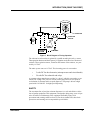


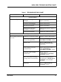
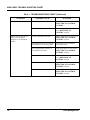
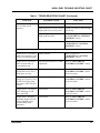
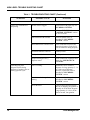
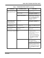

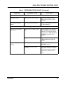

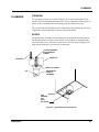
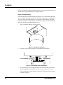
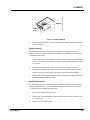
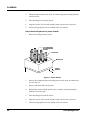

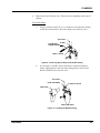


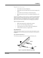


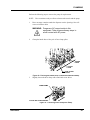
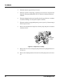

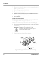

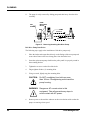
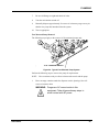
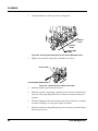
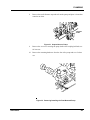


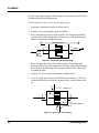


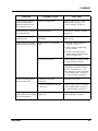

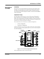

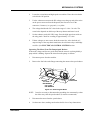

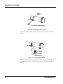
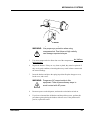


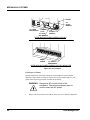


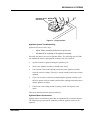

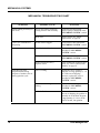
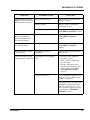
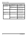


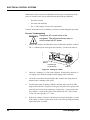
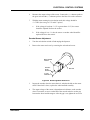

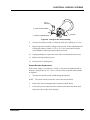
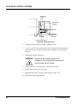

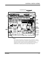
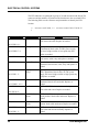
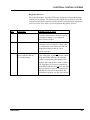
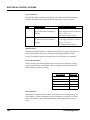


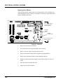
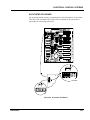
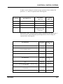

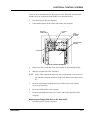
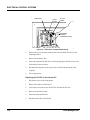
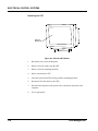
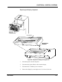
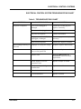
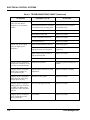
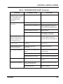


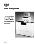


![[français] (PDF, 94 Ko)](http://vs1.manualzilla.com/store/data/006432506_1-bc39c642702577794c5e074042d111c4-150x150.png)