1
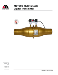
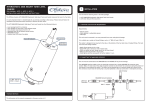
User’s Manual 9R216-IR
July 2012
MDT500 MULTIVARIABLE
DIGITAL TRANSMITTER
The Meriam Process Technologies (Meriam) Model MDT500
Multivariable Digital Transmitter is a complete flow solution
when used with a Meriam Laminar Flow Element (LFE) for air
and gas measurement with an accuracy of +/- 0.8% of the
calculated flow rate. Communication with the MDT500 is
achieved using the Meriam Serial Protocol (MSP), the Meriam
DLL or LabVIEW®. The Meriam Software Development Kit
(Meriam DLL, MDT Flow Calculator and MDT Config C#
sample application and source code, LabVIEW® executable
and VI’s) is included.
1
User’s Manual 9R216-IR
July 2012
Safety Warnings
The table below defines the safety symbols, signal words and corresponding safety messages used in the manual to
identify potential hazards and are intended to warn persons about hazards that could result in personal injury or
equipment damage.
This is the Read Instruction Manual symbol. This symbol indicates that you must read the instruction manual.
This is the Safety Alert symbol. When this symbol is located on a product (or nameplate label), this indicates that you
must read all sections of the user manual where the symbol appears to understand particularly important safety
information regarding electrical or mechanical connections.
This is the Safety Glasses symbol. This symbol indicates that you must wear approved safety glasses during the task.
This is the Safety Gloves symbol. This symbol indicates that you must wear approved safety gloves during the task.
Indicates a potentially hazardous situation which, if not avoided, will result in death or serious injury.
Indicates a potentially hazardous situation which, if not avoided, could result in death or serious injury.
Indicates a potentially hazardous situation which, if not avoided, could result in minor or moderate injury.
Indicates information essential for proper product installation, operation or maintenance.
Information in this document is subject to change without notice. Check the Meriam web site (www.meriam.com) for latest
manual revision.
For customer assistance please call your local Meriam representative or Meriam directly.
Meriam Process Technologies
10920 Madison Avenue
Cleveland, Ohio 44102
Telephone: (216) 281-1100
Fax: (216) 281-0228
E-mail: [email protected]
Web: www.meriam.com
®
LabVIEW is a registered trademark of National Instruments
2
User’s Manual 9R216-IR
July 2012
Table of Contents
Introduction.................................................................................... 4
CD ROM Resources...................................................................... 4
Interface Accessories .................................................................... 5
Installation and Operation ............................................................. 5
Zeroing the MDT500 ................................................................. 6
Firmware Reflash...................................................................... 7
Service and Calibration ................................................................. 7
Return Instructions ........................................................................ 8
Specifications /Certifications ......................................................... 9
3
User’s Manual 9R216-IR
July 2012
MDT500 Safety
Failure to follow all instructions could result in injury. Read, understand and follow all safety warnings
and instructions provided with this product. Also, meet or exceed your employer’s safety practices.
In no event shall Meriam be liable for any indirect, special, incidental, consequential or punitive damages or
for any lost profits arising out of or relating to any services provided by Meriam or its affiliates. It is not possible for
Meriam to identify all foreseeable uses/misuses, therefore all persons involved in commissioning, using or maintaining
this product must satisfy themselves that each intended application is acceptable.
Fire/Explosion Hazard. This instrument is not intrinsically safe. DO NOT use or service in areas
that may contain flammable gas or vapors, combustible dusts or ignitable fibers where an
unintended spark can cause a fire/explosion.
Do not exceed the Pressure Limits listed in the Specifications section of this manual. Failure to
operate within the specified pressure limit could result in death or serious injury.
Do not exceed the Maximum Input Voltage listed under “Power Requirements” in the Specification section of this
manual
Disconnect power before servicing.
Substitution of components may impair operation and safety.
Introduction
Congratulations! The MDT500 is the ideal compact, direct mounted solution for air and gas flow measurement. Follow
the instructions in this User’s Manual to set up the MDT500 to perform to its full potential. Thank you for choosing
Meriam.
Included with the MDT500
- RTD Probe
- USB cable
- CD-ROM
- A NIST traceable calibration certificate for Model numbers:
ZMDT-X-X
purchased without an LFE will receive a 6-point pressure calibration.
ZMDT-X-X-MT and LFE purchased as a system will receive a 3-point air flow calibration.
CD ROM Resources
Each MDT500 comes with a product CD ROM that includes the following resources:
- Meriam Software Development Kit
- Meriam Setup Utility
- Meriam Serial Protocol (MSP) Implementation Guide
- USB Drivers
®
- LabVIEW Drivers (VIs)
Please make use of these resources as referenced in this manual.
USB drivers must be installed on the host PC prior to communication with MDT500. Find these
drivers on the product CD.
4
User’s Manual 9R216-IR
July 2012
Interface Accessories
The following table lists part numbers for various accessories available to assist in configuration or communication.
Part Number
Z9A000003PN06
Description
MDT500 Product CD ROM
Z9P703
Male Adapter
ZA36894-3
Male Connector
Accessory Status
Standard, all models
Standard, LFE
mounted model
Standard, LFE
mounted model
Installation and Operation
The MDT500 is designed to be operated in conjunction with a Windows PC and the Meriam Software Development Kit
(SDK) which is provided for ease of integration with your systems. The SDK includes libraries for calculating flow rate
and for communicating with the device to take measurements and access configuration options. Example applications
are provided, as source code and as executables that implement key features of the Virtual Flow Instrument library.
The SDK can be used as both a .NET class library and a LabVIEW VI library. See the Meriam_SDK_Overview.pdf
and help file located in the SDK Documentation directory for details.
MDT/LFE Connections
Connections
The supplied RTD Probe must be connected prior to use. DO NOT allow the RTD probe sheath to directly
contact line voltage, e.g., 120VAC
5
User’s Manual 9R216-IR
July 2012
Use with high power (500 mA) USB ports or powered USB hubs only. Keep at least four inches from high power 3phase cables.
Do not run in parallel with 3-phase power cables. Cross existing AC power cables at right angle only when necessary
for routing purposes.
Zeroing the MDT500
Meriam recommends zeroing the MDT500 Differential Pressure sensor prior to use and periodically thereafter as
needed. Use the MDT Config example application included in the Meriam SDK to zero the sensor.
6
User’s Manual 9R216-IR
July 2012
Unzip %InstallationDirectory%\Meriam\SDK\Examples\CSharp\MDT Config Executable (this may have to be unzipped
to a location other than the Program Files or Program Files(x86) directory), launch MDT Config.exe, set the
appropriate Com Port and click the Connect button. Then click the Zero button in the Differential Pressure section.
Meriam recommends zeroing the MDT500 in its final mounting position to null any orientation
effects due to local gravity.
Firmware Reflash
Meriam periodically issues new operating firmware to improve MDT500 operation and features. All MDT500 units can
be reflashed with new firmware using the EI Reflash Utility software included on the CD.
Install Meriam Setup Utility. Connect the MDT500 to the host PC. Navigate to the Meriam Setup Utility directory and
open EI Reflash Utility.exe. Select COM Port and baud rate (115200). Click “Check Web” to download updates, then
“Auto Update” to ensure the MDT500 has the latest firmware and features.
Service and Calibration
In the event an MDT500 requires service or needs to be returned for factory recertification or re-calibration,
please contact Meriam at the numbers listed on the next page.
DO NOT send any unit in for service without first contacting Meriam for a Return Material
Authorization (RMA) number. If this number has not been obtained and clearly marked on the return
packaging, the unit will be returned at the shipper’s expense.
An RMA number will be provided by the Meriam Repair Department when you call, fax or e-mail your information.
Certification for Non-Hazardous Materials will also be required. The RMA number must accompany all incoming
packages to insure proper tracking, processing and repair work.
7
User’s Manual 9R216-IR
July 2012
To assist us in processing your service request, please have the Model & Serial Number of the unit available when
you call. This information is located on the product label.
Return Instructions
To lessen the possibility of shipping damage it is recommended the MDT500 be detached from the LFE for shipping.
1. When returning the LFE care should be taken to protect the LFE Matrix by covering up the open ends of the LFE.
2. Carefully detach the MDT500 from the LFE by loosening the 9/16 hex nuts on the two male connectors attached to the
MDT to separate from the LFE (see illustration).
3. Package MDT with sufficient protective KEM pack or bubble wrap to protect against damage during shipping.
4. Package LFE with sufficient protective KEM pack or bubble wrap to protect against damage during shipping.
5. Place both packaged LFE and MDT into one container with additional KEM pack or bubble wrap.
Meriam Process Technologies
10920 Madison Avenue
Cleveland, Ohio 44102
TELEPHONE: (216) 281-1100
FAX:
(216) 281-0228
E-mail: [email protected]
Web Site:
www.meriam.com
8
User’s Manual 9R216-IR
July 2012
Specifications /Certifications
Overall Technical Specifications
Media Compatibility
Clean, dry, non-corrosive gases only (brass, 316 SS, Viton, Silicon gel)
Software
Supported Operating Systems
Windows XP
Windows 7/Vista
.NET Framework 4.0
Software Development Kit (SDK)
Example Programs with Source Code in
LabVIEW® C# Application Programming Interface (API)
Supporting .NET (C# / VB)
COM Interop
Pressure Measurement
NIST Traceable Accuracy
+ 0.025 % of full scale including all effects of linearity, repeatability, hysteresis, and temperature (-20°C to +50°C)
Operating Temperature
-4°F to +122°F (-20°C to +50°C)
Pressure Update Rate
7 readings per second from both differential and absolute pressure sensors
Optional Pressure Ranges
Differential Sensor:
28 inches water column
10 inches water column
Absolute Sensor:
38 psia
100 psia
Over Range Limits
Differential Sensor:
2x range when pressurized on P1 (HI) side only; 150 psi when applied simultaneously to P1 (HI) & P2 (LO) sides
Absolute Sensor:
2x range
9
User’s Manual 9R216-IR
July 2012
Media Compatibility
Differential Sensor:
Clean, dry, non-corrosive gases only (brass, 316 SS, Viton®, Silicon gel)
Absolute Sensor:
Media compatible with 316 SS
Resistance/Temperature Measurement
NIST Traceable Accuracy
(+ 0.01 % of reading + 0.075 ohms) including all effects of linearity, repeatability, hysteresis, and temperature
Operating Temperature
-4°F to +122°F (-20°C to +50°C)
Temperature Update Rate
14 readings per second
Temperature Sensor Specifications
Accuracy
Class AA Tolerance Class (per IEC 60751)
Temperature Range
-58°F to +482°F (-50°C to +250°C)
Connector is +185°F (+85°C Max)
Material
316L Stainless Steel Sheath and Housing
Temperature Probe
Pt100 (100 Ohms at 0°C, .00385 TCR (alpha))
Probe Dimensions
¼” diameter, 6” long
Connections
5 meter M12 molded cordset
Mechanical
1
P1 & P2 Pressure Ports: ⁄4” NPT (female)
Flushing Ports: 5/16 – 24 SAE/MS J1926 (316L SS plugs
included)
Electrical / Communication
USB: type B female connector
Analog: circular, locking connector for RTD probe
Power Requirements
PC USB: high power (500 mA) USB port or USB hub (PC USB ports and USB hubs with power adapters that are
typically high power)
Note: User is responsible to provide controlled, fuse protected power from an IBM compatible computer via the USB port.
10
User’s Manual 9R216-IR
July 2012
Enclosure
Protection: IP40
Dimensions (in/mm): H x 2.6 (66), W x 3.6 (91), L x 5.6 (142)
Material: Plastic (ABS)
Weight: 1.5 lbs. (Hook up fittings add 0.26 lbs. (0.118 kg))
Mounting
Laminar Flow Element mounting hardware provided
Temperature Limits
Operating: -4 to 122°F (-20 to 50°C)
Storage: -40 to 185°F (-40 to 85°C)
Humidity Limits
5 – 95% RH operating
CE Marking
EN 61326-1 Electrical equipment for measurement, control
1,2
and laboratory use - EMC requirements
2
IEC 61010 Safety Requirements for Electrical Equipment for Measurement, Control and Laboratory Use
1 – FOR USE ONLY IN A CONTROLLED EMC ENVIRONMENT, TYPICALLY FOUND IN A TEST, MEASUREMENT AND CALIBRATION ENVIRONMENT.
2 – CLASSIFIED AS CAT-1 (VOLTAGES NOT PRESENT OR MEASURED ABOVE 60VDC)
Hazardous Material and Recycling Compliance
This product is compliant with the European directives:
- RoHS directive 2002/95/EC, "Reduction of Hazardous Substances", and
- WEEE 2002/96/EC, "Waste from Electrical and Electronic Equipment".
The WEEE mark informs users of electrical and electronic equipment to ensure proper disposal.
Spare Parts
Z9P703
ZA36894-3
Z9P273
Z9P713
Z9P521
Adapter-Male-Machine – ¼” Tube X ¼” MNPT Brass
Male Connector - ¼” Tube X ¼” MNPT Brass
Cable, USB, Type “A” To Mini “B”
Cable, RTD-4 Pos Plug-Socket 5.0M
Probe-RTD Sensor
11