1
MELSEC iQ-F
FX5 Programming Manual (Program Design)
SAFETY PRECAUTIONS
(Read these precautions before using this product.)
Before using the FX5 PLCs, please read the manual supplied with each product and the relevant manuals introduced in that
manual carefully and pay full attention to safety to handle the product correctly.
Store this manual in a safe place so that it can be taken out and read whenever necessary. Always forward it to the end user.
INTRODUCTION
This manual describes the instructions and functions required for programming of the FX5. Please read this manual and the
relevant manuals and understood the functions and performance of the FX5 PLCs before attempting to use the unit.
It should be read and understood before attempting to install or use the unit. Store this manual in a safe place so that you can
take it out and read it whenever necessary. Always forward it to the end user.
When utilizing the program examples introduced in this manual to the actual system, always confirm that it poses no problem
for control of the target system.
Regarding use of this product
• This product has been manufactured as a general-purpose part for general industries, and has not been designed or
manufactured to be incorporated in a device or system used in purposes related to human life.
• Before using the product for special purposes such as nuclear power, electric power, aerospace, medicine or passenger
movement vehicles, consult with Mitsubishi Electric.
• This product has been manufactured under strict quality control. However when installing the product where major
accidents or losses could occur if the product fails, install appropriate backup or failsafe functions in the system.
Note
• If in doubt at any stage during the installation of the product, always consult a professional electrical engineer who is
qualified and trained to the local and national standards. If in doubt about the operation or use, please consult the nearest
Mitsubishi Electric representative.
• Since the examples indicated by this manual, technical bulletin, catalog, etc. are used as a reference, please use it after
confirming the function and safety of the equipment and system. Mitsubishi Electric will accept no responsibility for actual
use of the product based on these illustrative examples.
• This manual content, specification etc. may be changed without a notice for improvement.
• The information in this manual has been carefully checked and is believed to be accurate; however, if you have noticed a
doubtful point, a doubtful error, etc., please contact the nearest Mitsubishi Electric representative. When doing so, please
provide the manual number given at the end of this manual.
1
CONTENTS
SAFETY PRECAUTIONS . . . . . . . . . . . . . . . . . . . . . . . . . . . . . . . . . . . . . . . . . . . . . . . . . . . . . . . . . . . . . . . . . . . .1
INTRODUCTION . . . . . . . . . . . . . . . . . . . . . . . . . . . . . . . . . . . . . . . . . . . . . . . . . . . . . . . . . . . . . . . . . . . . . . . . . . .1
RELEVANT MANUALS . . . . . . . . . . . . . . . . . . . . . . . . . . . . . . . . . . . . . . . . . . . . . . . . . . . . . . . . . . . . . . . . . . . . . .4
TERMS . . . . . . . . . . . . . . . . . . . . . . . . . . . . . . . . . . . . . . . . . . . . . . . . . . . . . . . . . . . . . . . . . . . . . . . . . . . . . . . . . .4
CHAPTER 1
OUTLINE
6
CHAPTER 2
PROGRAM CONFIGURATION
8
2.1
Program Block . . . . . . . . . . . . . . . . . . . . . . . . . . . . . . . . . . . . . . . . . . . . . . . . . . . . . . . . . . . . . . . . . . . . . . . . . . . 9
CHAPTER 3
PROGRAM ORGANIZATION UNIT (POU)
10
3.1
Function (FUN). . . . . . . . . . . . . . . . . . . . . . . . . . . . . . . . . . . . . . . . . . . . . . . . . . . . . . . . . . . . . . . . . . . . . . . . . . 11
3.2
Function Block (FB) . . . . . . . . . . . . . . . . . . . . . . . . . . . . . . . . . . . . . . . . . . . . . . . . . . . . . . . . . . . . . . . . . . . . . 15
CHAPTER 4
LABELS
21
4.1
Type . . . . . . . . . . . . . . . . . . . . . . . . . . . . . . . . . . . . . . . . . . . . . . . . . . . . . . . . . . . . . . . . . . . . . . . . . . . . . . . . . . 21
4.2
Class . . . . . . . . . . . . . . . . . . . . . . . . . . . . . . . . . . . . . . . . . . . . . . . . . . . . . . . . . . . . . . . . . . . . . . . . . . . . . . . . . . 22
4.3
Data Type . . . . . . . . . . . . . . . . . . . . . . . . . . . . . . . . . . . . . . . . . . . . . . . . . . . . . . . . . . . . . . . . . . . . . . . . . . . . . . 22
4.4
Arrays . . . . . . . . . . . . . . . . . . . . . . . . . . . . . . . . . . . . . . . . . . . . . . . . . . . . . . . . . . . . . . . . . . . . . . . . . . . . . . . . . 25
4.5
Structures. . . . . . . . . . . . . . . . . . . . . . . . . . . . . . . . . . . . . . . . . . . . . . . . . . . . . . . . . . . . . . . . . . . . . . . . . . . . . . 27
4.6
Constant . . . . . . . . . . . . . . . . . . . . . . . . . . . . . . . . . . . . . . . . . . . . . . . . . . . . . . . . . . . . . . . . . . . . . . . . . . . . . . . 29
4.7
Precautions . . . . . . . . . . . . . . . . . . . . . . . . . . . . . . . . . . . . . . . . . . . . . . . . . . . . . . . . . . . . . . . . . . . . . . . . . . . . 30
CHAPTER 5
5.1
LADDER DIAGRAM
32
Configuration . . . . . . . . . . . . . . . . . . . . . . . . . . . . . . . . . . . . . . . . . . . . . . . . . . . . . . . . . . . . . . . . . . . . . . . . . . . 32
Ladder symbols . . . . . . . . . . . . . . . . . . . . . . . . . . . . . . . . . . . . . . . . . . . . . . . . . . . . . . . . . . . . . . . . . . . . . . . . . . 32
Program execution order . . . . . . . . . . . . . . . . . . . . . . . . . . . . . . . . . . . . . . . . . . . . . . . . . . . . . . . . . . . . . . . . . . . 33
5.2
Inline ST . . . . . . . . . . . . . . . . . . . . . . . . . . . . . . . . . . . . . . . . . . . . . . . . . . . . . . . . . . . . . . . . . . . . . . . . . . . . . . . 34
5.3
Statements and Notes . . . . . . . . . . . . . . . . . . . . . . . . . . . . . . . . . . . . . . . . . . . . . . . . . . . . . . . . . . . . . . . . . . . . 35
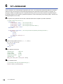
CHAPTER 6
6.1
ST LANGUAGE
36
Configuration . . . . . . . . . . . . . . . . . . . . . . . . . . . . . . . . . . . . . . . . . . . . . . . . . . . . . . . . . . . . . . . . . . . . . . . . . . . 37
Delimiter . . . . . . . . . . . . . . . . . . . . . . . . . . . . . . . . . . . . . . . . . . . . . . . . . . . . . . . . . . . . . . . . . . . . . . . . . . . . . . . 38
Operator . . . . . . . . . . . . . . . . . . . . . . . . . . . . . . . . . . . . . . . . . . . . . . . . . . . . . . . . . . . . . . . . . . . . . . . . . . . . . . . 38
Syntax . . . . . . . . . . . . . . . . . . . . . . . . . . . . . . . . . . . . . . . . . . . . . . . . . . . . . . . . . . . . . . . . . . . . . . . . . . . . . . . . . 39
Constant . . . . . . . . . . . . . . . . . . . . . . . . . . . . . . . . . . . . . . . . . . . . . . . . . . . . . . . . . . . . . . . . . . . . . . . . . . . . . . . 46
Label and device . . . . . . . . . . . . . . . . . . . . . . . . . . . . . . . . . . . . . . . . . . . . . . . . . . . . . . . . . . . . . . . . . . . . . . . . . 46
Comment . . . . . . . . . . . . . . . . . . . . . . . . . . . . . . . . . . . . . . . . . . . . . . . . . . . . . . . . . . . . . . . . . . . . . . . . . . . . . . . 48
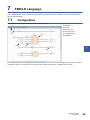
CHAPTER 7
7.1
FBD/LD Language
49
Configuration . . . . . . . . . . . . . . . . . . . . . . . . . . . . . . . . . . . . . . . . . . . . . . . . . . . . . . . . . . . . . . . . . . . . . . . . . . . 49
Program unit . . . . . . . . . . . . . . . . . . . . . . . . . . . . . . . . . . . . . . . . . . . . . . . . . . . . . . . . . . . . . . . . . . . . . . . . . . . . 50
Worksheet . . . . . . . . . . . . . . . . . . . . . . . . . . . . . . . . . . . . . . . . . . . . . . . . . . . . . . . . . . . . . . . . . . . . . . . . . . . . . . 54
Constant . . . . . . . . . . . . . . . . . . . . . . . . . . . . . . . . . . . . . . . . . . . . . . . . . . . . . . . . . . . . . . . . . . . . . . . . . . . . . . . 54
Labels and devices . . . . . . . . . . . . . . . . . . . . . . . . . . . . . . . . . . . . . . . . . . . . . . . . . . . . . . . . . . . . . . . . . . . . . . . 54
7.2
Program execution order . . . . . . . . . . . . . . . . . . . . . . . . . . . . . . . . . . . . . . . . . . . . . . . . . . . . . . . . . . . . . . . . . 55
The order of executions of program units . . . . . . . . . . . . . . . . . . . . . . . . . . . . . . . . . . . . . . . . . . . . . . . . . . . . . . 55
2
INDEX
56
REVISIONS. . . . . . . . . . . . . . . . . . . . . . . . . . . . . . . . . . . . . . . . . . . . . . . . . . . . . . . . . . . . . . . . . . . . . . . . . . . . . .58
WARRANTY . . . . . . . . . . . . . . . . . . . . . . . . . . . . . . . . . . . . . . . . . . . . . . . . . . . . . . . . . . . . . . . . . . . . . . . . . . . . .59
CONTENTS
TRADEMARKS . . . . . . . . . . . . . . . . . . . . . . . . . . . . . . . . . . . . . . . . . . . . . . . . . . . . . . . . . . . . . . . . . . . . . . . . . . .60
3
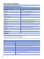
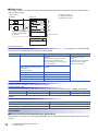
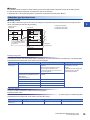
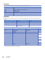
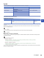
RELEVANT MANUALS
User's manuals for the applicable modules
Manual name <manual number>
Description
MELSEC iQ-F FX5 User's Manual (Startup)
<JY997D58201>
Performance specifications, procedures before operation, and troubleshooting of the
CPU module.
MELSEC iQ-F FX5U User's Manual (Hardware)
<JY997D55301>
Describes the details of hardware of the FX5U CPU module, including input/output
specifications, wiring, installation, and maintenance.
MELSEC iQ-F FX5UC User's Manual (Hardware)
<JY997D61401>
Describes the details of hardware of the FX5UC CPU module, including input/output
specifications, wiring, installation, and maintenance.
MELSEC iQ-F FX5 User's Manual (Application)
<JY997D55401>
Describes basic knowledge required for program design, functions of the CPU
module, devices/labels, and parameters.
MELSEC iQ-F FX5 Programming Manual (Program Design)
<JY997D55701> (This manual)
Describes specifications of ladders, ST, FBD/LD, and other programs and labels.
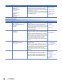
MELSEC iQ-F FX5 Programming Manual (Instructions, Standard
Functions/Function Blocks)
<JY997D55801>
Describes specifications of instructions and functions that can be used in programs.
MELSEC iQ-F FX5 User's Manual (Serial Communication)
<JY997D55901>
Describes N:N network, MELSEC Communication protocol, inverter communication,
non-protocol communication, and predefined protocol support.
MELSEC iQ-F FX5 User's Manual (MELSEC Communication Protocol)
<JY997D60801>
Explains methods for the device that is communicating with the CPU module by MC
protocol to read and write the data of the CPU module.
MELSEC iQ-F FX5 User's Manual (MODBUS Communication)
<JY997D56101>
Describes MODBUS serial communication.
MELSEC iQ-F FX5 User's Manual (Ethernet Communication)
<JY997D56201>
Describes the functions of the built-in Ethernet port communication function.
MELSEC iQ-F FX5 User's Manual (SLMP)
<JY997D56001>
Explains methods for the device that is communicating with the CPU module by
SLMP to read and write the data of the CPU module.
MELSEC iQ-F FX5 User's Manual (Positioning Control)
<JY997D56301>
Describes the built-in positioning function.
MELSEC iQ-F FX5 User's Manual (Analog Control)
<JY997D60501>
Describes the analog function.
GX Works3 Operating Manual
<SH-081215ENG>
System configuration, parameter settings, and online operations of GX Works3.
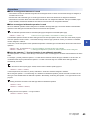
TERMS
Unless otherwise specified, this manual uses the following terms.
• indicates a variable part to collectively call multiple models or versions.
(Example) FX5U-32MR/ES, FX5U-32MT/ES FX5U-32M/ES
• For details on the FX3 devices that can be connected with the FX5, refer to User's Manual (Hardware) of the CPU module
used.
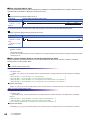
Terms
Description
■Devices
4
FX5
Abbreviation of FX5 PLCs
FX3
Generic term for FX3S, FX3G, FX3GC, FX3U, and FX3UC PLCs
FX5 CPU module
Generic term for FX5U CPU module and FX5UC CPU module
FX5U CPU module
Generic term for FX5U-32MR/ES, FX5U-32MT/ES, FX5U-32MT/ESS, FX5U-64MR/ES, FX5U-64MT/ES,
FX5U-64MT/ESS, FX5U-80MR/ES, FX5U-80MT/ES, and FX5U-80MT/ESS
FX5UC CPU module
Generic term for FX5UC-32MT/D and FX5UC-32MT/DSS
Extension module
Generic term for FX5 extension modules and FX3 function modules
• FX5 extension module
Generic term for I/O modules, FX5 extension power supply module, and FX5 intelligent function module
• FX3 extension module
Generic term for FX3 extension power supply module and FX3 special function blocks
Extension module (extension cable type)
Input modules (extension cable type), Output modules (extension cable type), Bus conversion module
(extension cable type), and Intelligent function modules
Extension module (extension connector type)
Input modules (extension connector type), Output modules (extension connector type), Input/output
modules, Bus conversion module (extension connector type), and Connector conversion module (extension
connector type)
Terms
Description
I/O module
Generic term for input modules, output modules, Input/output modules, and powered input/output modules
Input module
Generic term for Input modules (extension cable type) and Input modules (extension connector type)
• Input module (extension cable type)
Generic term for FX5-8EX/ES and FX5-16EX/ES
• Input module (extension connector type)
Generic term for FX5-C32EX/D and FX5-C32EX/DS
Output module
• Output module (extension cable type)
• Output module (extension connector type)
Input/output modules
Generic term for output modules (extension cable type) and output modules (extension connector type)
Generic term for FX5-8EYR/ES, FX5-8EYT/ES, FX5-8EYT/ESS, FX5-16EYR/ES, FX5-16EYT/ES, and
FX5-16EYT/ESS
Generic term for FX5-C32EYT/D and FX5-C32EYT/DSS
Generic term for FX5-C32ET/D and FX5-C32ET/DSS
Powered input/output module
Generic term for FX5-32ER/ES, FX5-32ET/ES, and FX5-32ET/ESS
Extension power supply module
Generic term for FX5 extension power supply module and FX3 extension power supply module
• FX5 extension power supply module
Different name for FX5-1PSU-5V
• FX3 extension power supply module
Different name for FX3U-1PSU-5V
Intelligent module
The abbreviation for intelligent function modules
Intelligent function module
Generic term for FX5 intelligent function modules and FX3 intelligent function modules
• FX5 intelligent function module
Generic term for FX5 intelligent function modules
• FX3 intelligent function module
Generic term for FX3 special function blocks
Simple motion module
Different name for FX5-40SSC-S
Expansion board
Generic term for board for FX5U CPU module
• Communication board
Expansion adapter
Generic term for FX5-232-BD, FX5-485-BD, and FX5-422-BD-GOT
Generic term for adapter for FX5 CPU module
• Communication adapter
Generic term for FX5-232ADP and FX5-485ADP
• Analog adapter
Generic term for FX5-4AD-ADP and FX5-4DA-ADP
Bus conversion module
Generic term for Bus conversion module (extension cable type) and Bus conversion module (extension
connector type)
• Bus conversion module (extension cable
type)
Different name for FX5-CNV-BUS
• Bus conversion module (extension connector
type)
Different name for FX5-CNV-BUSC
Battery
Different name for FX3U-32BL
Peripheral device
Generic term for engineering tools and GOTs
GOT
Generic term for Mitsubishi Graphic Operation Terminal GOT1000 and GOT2000 series
■Software packages
Engineering tool
The product name of the software package for the MELSEC programmable controllers
GX Works3
The product name of the software package, SWnDND-GXW3, for the MELSEC programmable controllers
(The 'n' represents a version.)
■Program
Operand
A generic term for items, such as source data (s), destination data (d), number of devices (n), and others,
used to configure instructions and functions
Device
A device (X, Y, M, D, or others) in a CPU module
Buffer memory
A memory in an intelligent function module, where data (such as setting values and monitoring values) are
stored.
POU
Defined unit of a program. Use of POUs enables a program to be divided into units according to process or
function, and each unit to be programmed individually.
5
1
OUTLINE
This manual describes program configurations, content, and method for creating programs.
For how to create, edit, or monitor programs using the engineering tool, refer to the following.
GX Works3 Operating Manual
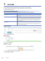
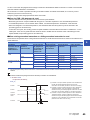
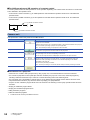
Type of programming languages
With the FX5 series, the optimal programming language can be selected according to the application.
Programming language
Description
Ladder diagram
Ladder diagram is a graphic language that indicates circuits using contacts, coils, and others.
The ladder diagram describes logic circuits with symbolized contacts and coils for easy-to-understand
sequence control.
Structured text language (ST language)
ST language is a text language that describes programs with IF statements, operators, and others.
Because operation processing that is difficult to describe in ladder diagram can be easily and briefly
described with ST language, ST language is suitable for applications requiring complicated arithmetic
operation or comparative operation. With ST language, programs can be easily described with syntax
using selective branches with conditional statements and repetition by repetitive statements in the
same way as C language.
Function block diagram/ladder diagram
(FBD/LD language)
This is a graphic language that describes a program by wiring blocks for specific processing (function
elements, FB elements), variable elements, and constant elements along with the flows of data and
signals.
You can easily create a program that may be complicated to create by using a ladder program. So you
can enhance the productivity of programs.
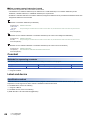
■Ladder diagram
When using ladder diagram, refer to the following.
Page 32 LADDER DIAGRAM
■ST language
When using ST language, refer to the following.
Page 36 ST LANGUAGE
■FBD/LD language
When using FBD/LD language, refer to the following.
Page 49 FBD/LD Language
6
1 OUTLINE
• Ladder diagram and FBD/LD language are for customers who have knowledge or experience of sequence
1
control and logic circuits.
• ST language is for customers who have knowledge or experience of the C language programming.
• By using labels in a program, the readability of the program is improved, and activating a program for the
system with a different module configuration is easy.
1 OUTLINE
7
2
PROGRAM CONFIGURATION
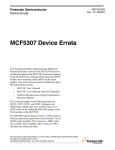
Using the engineering tool, multiple programs and POUs (Program Organization Units) can be created.
Thus, programs and POUs can be sorted by processing.
This chapter describes the program configuration.
Project
Program file 1
Program file 2
POUs
Function block
Program block
Program block
Function block
Function
Program block
Function
Function
For the POU, refer to the following.
Page 10 PROGRAM ORGANIZATION UNIT (POU)
Project
A project is a collection of data (including programs and parameters) to be executed by the CPU module.
Only one project can be written to one CPU module.
For one project, one or more program files need to be created.
Program file
A program file is a collection of programs and POUs.
One program file consists of one or more program blocks.
The operation on the program file level can be changed, such as, the execution type of a program can be switched from scan
execution type to standby type, or whether to write data to the CPU module.
8
2 PROGRAM CONFIGURATION
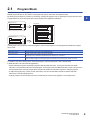
2.1
Program Block
A program block is a unit of a program.
Multiple program blocks can be created in one program file, and are executed in the registered order.
By dividing program blocks by functions or processing, changing the program order or replacing the program becomes easy.
2
Program blocks are stored in program files of each program in the registration destination.
Program block 1
Program file
Program block 2
Creating main routine programs, subroutine programs, and interrupt programs for each program block makes the program
easy to read.
Type
Description
Main routine program
Program segment from the step 0 to the FEND instruction
Subroutine program
Program segment from a pointer (P) to the RET instruction
Executed only when a subroutine call instruction (CALL instruction etc.) is executed.
Interrupt program
Program segment from an interrupt pointer (I) to the IRET instruction
When an interrupt is triggered, the interrupt program corresponding to the interrupt pointer number is executed.
For details on the main routine program, subroutine program, and interrupt program, refer to the following.
MELSEC iQ-F FX5 User's Manual (Application)
• Create subroutine programs and interrupt programs after the FEND instruction. The program area after the FEND
instruction is not executed as the main routine program. For example, when the FEND instruction is used at the end of the
second program block, the third program block and later are handled as subroutine programs or interrupt programs.
• To make the program easy to read, use twin instructions, such as FOR and NEXT instructions and MC and MCR
instructions, in the same program block.
• A simple program can be executed by the CPU module with just a main routine program in one program block.
2 PROGRAM CONFIGURATION
2.1 Program Block
9
3
PROGRAM ORGANIZATION UNIT (POU)
The POU includes the following types.
• Function
• Function block
The processing of each POU can be described in a programming language according to the control. POUs are called from a
program block, and then executed.
Project
Program file
Use
POU
Program block
POU folder
POU
POU
Function block
Function
A structured program is a program created by components. Processes in lower levels of hierarchical program
are divided to several components according to their processing information and functions.
Each component is designed to have a high degree of independence for easy addition and replacement.
The following shows examples of the process that would be ideal to be structured.
• A process that is used repeatedly in a program
• A process that can be divided into functions
This chapter describes two types of POUs using labels.
Devices can also be used in the program of a function or function block. For details on devices, refer to the following.
MELSEC iQ-F FX5 User's Manual (Application)
10
3 PROGRAM ORGANIZATION UNIT (POU)
3.1
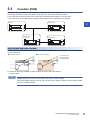
Function (FUN)
Functions are a type of POU used by program blocks, function blocks, or other functions.
The function sends back a value to the call source after execution. The value is called return values.
The function always outputs the same return value as the processing result in response to the same input.
The function can be re-used effectively by defining a simple, independent, and frequently used algorithm.
Function
Program block
3
FUN
Function block
or function
Program block
FUN
FB or FUN
Input variable and output variable
For a function, input variables and output variables can be defined. Output variable can be created to output data separate
from the return value.
■Case of ladder diagram
■Case of FBD/LD language
(1)
(1)
(2)
(2)
(3)
(3)
(1) Function name
(2) Input variables
(3) Output variables
For classes for which input variables or output variables can be set, refer to the following.
Page 22 Class
Variables defined in a function are overwritten every time the function is called.
To retain the variable values at each call, use a function block or design a program so that an output variable
is saved in a different variable.
3 PROGRAM ORGANIZATION UNIT (POU)
3.1 Function (FUN)
11
EN/ENO
An EN (enable input) and ENO (enable output) can be appended to a function to control its execution.
• A Boolean variable used as an executing condition of a function is set to an EN.
• A function with an EN is executed only when the executing condition of the EN is TRUE.
• A Boolean variable used as an output of function execution result is set to an ENO.
For the Boolean variable, refer to the following.
Page 22 Data Type
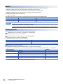
The table below shows the "ENO" status corresponding to the "EN" status and the operation result.
EN
ENO
Operation result
TRUE (Executes operation)
TRUE
Operation output value
FALSE (Stops operation)
FALSE
Indefinite value
• Setting an output label to an ENO is not required.
• When an EN or ENO is used for standard functions, functions with an EN are shown as "Function name_E".
Creating programs
The program of a function can be created by using the engineering tool.
Navigation window "FB/FUN" Right-click "Add New Data"
The created program is stored in the FB/FUN file.
[CPU Parameter] "Program Setting" "FB/FUN File Setting"
Up to 64 programs can be stored in one FB/FUN file.
For details on program creation, refer to the following.
Item
Reference
How to create function programs
GX Works3 Operating Manual
Number of FB/FUN files that can be written to a CPU module
MELSEC iQ-F FX5 User's Manual (Startup)
■Applicable devices and labels
The following table lists the devices and labels that can be used in function programs.
: Applicable, : Applicable only by instructions (Not applicable as a label indicating a program step), : Not applicable
Type of device/label
Label (other than pointer type)
Local label
*1
Pointer type global label
Pointer type local label
Device
Global device
Pointer
Global pointer
Label (pointer type)
*1
12
Availability
Global label
The timer, retentive timer, counter and long counter types cannot be used.
3 PROGRAM ORGANIZATION UNIT (POU)
3.1 Function (FUN)
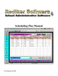
Operation overview
The program of a function is stored in the FB/FUN file and called by the calling source program when executed
Execution flow
(Program file)
Main program
(FB file)
FUN1 program
(FB file)
FUN3 program
2
1
3
FUN3
FUN1
5
3
4
(FB file)
FUN2 program
FUN2
6
7
You can nest all function blocks and functions up to 32 times.
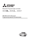
Labels defined by a function
The labels defined by a function are assigned in the temporary areas of the storage-target memory during execution of the
function, and the areas are freed after the processing completes.
The following figure shows the label assignments while the above functions are being executed.
1
Main program being
executed
2
FUN1 being executed
(before FUN3 is called)
3
FUN3 being executed
4
FUN1 being executed
(after FUN3 is executed)
Label area of FUN3
Label area of FUN1
5
Main program being
executed
6
FUN2 being executed
Label area of FUN1
Label area of FUN1
7
Main program being
executed
Label area of FUN2
For the types of labels that can be defined by a function, refer to the following.
Page 22 Class
The label to be defined by a function must be initialized by a program before the first access because the label
value will be undefined.
Number of steps
To call a function, the number of steps required is not only for the program itself but also for the processing that passes the
argument and return value, the processing that calls the program, and additional steps used by the system.
■Program
The number of steps required for a function program is the total number of instruction steps plus at least additional 13 steps
used by the system. For the number of steps required for each instruction, refer to the following.
MELSEC iQ-F FX5 Programming Manual (Instructions, Standard Functions/Function Blocks)
3 PROGRAM ORGANIZATION UNIT (POU)
3.1 Function (FUN)
13
■Calling source
When calling a function, the calling source generates the processing that passes the argument and return value before and
after the call processing.
Program block 1
(displayed)
(1) Passing the argument
(2) Calling the FUN1 program
(3) Passing the return value
Program file
M0
D0
FUN1
Y20
M10
D10
FUN2
Y40
MOV D0 XX
(1)
M0
(2)
Y20
(3)
…
The call-target program
is replaced with the call
instruction.
FUNCall FUN1
Calling the function
FB file
FUN1 program
Passing the argument
The instruction used to pass the argument differs depending on the class and data type of the argument. The following table
summarizes the instructions that can be used to pass the argument.
Argument class
Data type
Instruction used
Number of steps
VAR_INPUT
Bit
LD+OUT
LD+MOVB
(Which of the above instructions is used is
determined by the combination of the
programming language, type of function, and
type of input argument.)
For the number of steps required for
each instruction, refer to the
following.
MELSEC iQ-F FX5 Programming
Manual (Instructions, Standard
Functions/Function Blocks)
Word [Unsigned]/Bit String [16-bit]
Double Word [Unsigned]/Bit String [32-bit]
Word [Signed]
Double Word [Signed]
LD+MOV
LD+DMOV
FLOAT [Single Precision]
LD+EMOV
Time
LD+DMOV
String(32)
LD+$MOV
Array, Structure
LD+BMOV
Calling the program
At least 16 steps are required to call the program of a function.
Passing the return value
The instruction and the number of steps used for passing the return value are identical to those for passing the argument.
Argument class
Data type
Instruction used
Number of steps
VAR_OUTPUT
Same as for passing the argument
Same as for passing the argument
Same as for passing the argument
EN/ENO
The following table lists the number of steps required for EN/ENO.
Item
Number of steps
EN
6
ENO
4
Precautions
■Global pointer/local pointer/pointer type global labels
Global pointer, local pointer, and pointer type global labels cannot be used as labels indicating program steps in the function
program.
14
3 PROGRAM ORGANIZATION UNIT (POU)
3.1 Function (FUN)
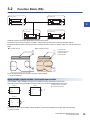
3.2
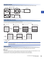
Function Block (FB)
Function blocks are a type of POU used by program blocks or other function blocks.
Function block
Function block
FB
3
Function block
Function block
FB
FB
Unlike the function, the function block does not output return values.
The function block can save a value in a variable, and thus the input status and processing result are retained.
Because the retained value is used for the next processing, the same result is not always output even with the same input
value.
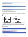
■Case of ladder diagram
■Case of FBD/LD language
(1)
(1)
(2)
(2)
(3)
(3)
(4)
(4)
(1)
(2)
(3)
(4)
Instance name
Function block name
Output variables
Input variables
To use the function block in a program, instances must be defined.
Page 16 Instances
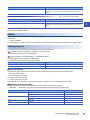
Input variable, output variable, and input/output variable
Input variables, output variables, and input/output variables must be defined for function blocks.
The function block can output multiple operation results and can also be created without any output.
Instance
SR
_S1
(1) Multiple outputs are returned.
(2) No outputs are returned.
Instance
SAMPLE_FB1
IN_Bool
Q1
(2)
iTim
RESET
lCnt
Instance
CTD
CD
LOAD
Q
(1)
CV
PV
For classes for which input variables, output variables, or input/output variables can be set, refer to the following.
Page 22 Class
3 PROGRAM ORGANIZATION UNIT (POU)
3.2 Function Block (FB)
15
Internal variable
For the function block, internal variables can be used.
For classes for which internal variables can be set, refer to the following.
Page 22 Class
External variable
For the function block, external variables can be used.
For classes for which external variables can be set, refer to the following.
Page 22 Class
Instances
■Instances
To use the function block, instances must be created.
By creating instances of the function block, the function block can be used by calling from a program or another function
block. Multiple instances can be created from one function block definition.
To create an instance, define it as a global label or local label of the POU that uses the function block. The instance can be
defined as an array.
The same function block can be used in different instances in one POU. For each instance of a function block, labels are
assigned to different areas in memory. Even though the same label names are used, different states are held for each
instance.
Ex.
Instance B
Instance A
Function block
bLabel1
uLabel10 ON
bLabel4
Count contact
uLabel2
uLabel12 10
uLabel13 OFF
Count contact
bLabel3
Output contact
Set value
uLabel10 ON
uLabel5
uLabel12 500
uLabel13 ON
bLabel6
Output contact
Set value
uLabel11 7
uLabel11 500
Current value
Current value
The above function block starts counting current value when the input variables (Count contact) turn on and turns on the
output variable (Output contact) when the current value held in the internal variable reaches the set value.
Instance A and B are the same function blocks, but instances A and B hold different states because the instance is different.
In the above example, output variable (Output contact) of instance B is already turned ON, but output variable (Output
contact) of instance A is not turned ON. Because the current value of instance A does not reach the set value, output variable
(Output contact) of instance A is not turn ON.
■Structure of instance
An instance consists of the following data areas.
Data area
Description
Local label area
Used to assign local labels of the function block.
Local latch label area
Used to assign latched local labels of the function block.
■Capacity of instance
The capacity of each data area of an instance should be calculated as follows.
Local label area
Capacity of local label area of instance = Total capacity of data of non-latched local labels + Capacity of reserved area
16
Breakdown
Description
Capacity of non-latched local labels
Total capacity of the data areas used for local labels.
3 PROGRAM ORGANIZATION UNIT (POU)
3.2 Function Block (FB)
Breakdown
Description
Capacity of reserved area
The capacity of the area reserved to add non-latched local labels and local
instances when executing the online program change function. (fixed at 48
words)
Local latch label area
Capacity of local latch label area of instance = Total capacity of data of latched local labels + Capacity of reserved area
Breakdown
Description
Capacity of latched local labels
Total capacity of the data areas used for latched local labels.
Capacity of reserved area
The capacity of the area reserved to add latched local labels and local
instances when executing the online program change function. (fixed at 16
words)
3
The local label area capacity is assigned by using the engineering tool. For details, refer to the following.
GX Works3 Operating Manual
EN/ENO
An EN (enable input) and ENO (enable output) can be appended to a function block, in the same way as a function, to control
its execution.
Page 12 EN/ENO
An actual argument must be assigned to EN when the instance of the function block to which an EN/ENO is added is called.
Creating programs
The program of a function block can be created by using the engineering tool.
Navigation window "FB/FUN" Right-click "Add New Data"
The created program is stored in the FB/FUN file.
[CPU Parameter] "Program Setting" "FB/FUN File Setting"
Up to 64 programs can be stored in one FB/FUN file.
For details on program creation, refer to the following.
Item
Reference
How to create function programs
GX Works3 Operating Manual
Number of FB/FUN files that can be written to a CPU module
MELSEC iQ-F FX5 User's Manual (Startup)
■Type of programs
There are two types of function blocks and the program of each function block type is stored in different ways.
• Macro type function block
• Subroutine type function block
For details, refer to the following.
Page 18 Operation overview
The above cannot be selected for module function blocks, standard functions, and standard function blocks.
■Applicable devices and labels
The following table lists the devices and labels that can be used by function block programs.
: Applicable, : Applicable only by instructions (Not applicable as a label indicating a program step)
Type of device/label
Availability
Global label
Local label
Pointer-type global label
Pointer-type local label
Device
Global device
Pointer
Global pointer
Label (other than pointer type)
Label (pointer type)
3 PROGRAM ORGANIZATION UNIT (POU)
3.2 Function Block (FB)
17
Operation overview
■Macro type function blocks
The program of a macro type function block is loaded by the calling source program according to the execution flow. At the
time of program execution, the loaded program is executed in the same way as the main program.
Use a macro type function block when giving higher priority to the processing speed of the program.
(Program file)
Main program
Execution flow
Actual structure of
main program
FB1_a
FB1
FB1 program
FB3 program
FB2_a
FB2
FB2 program
(1)
(1) The FB1 program is loaded into the main program
and executed.
(2) FB3 is loaded into the FB1 program.
(3) The FB2 program is loaded into the main program
and executed in the same way as the FB1
program.
(2)
(3)
■Subroutine type function blocks
The program of a subroutine type function block is stored in the FB/FUN file and called by the calling source program when
executed.
Use a subroutine type function block to reduce the program size.
(Program file)
Main program
Execution flow
(FB file)
FB1 program
FB3_a
FB3
FB1_a
FB1
(FB file)
FB3 program
(FB file)
FB2 program
FB2_a
FB2
You can nest all of function blocks, and functions up to 32 times.
Macro type function blocks
■Calling source
When calling a macro type function block, the calling source loads the call-target program during compilation.
Program block 1 (displayed)
FB1_a
FB1
Program file
FB1 program
(FB1_a)
FB1_b
FB1
FB1 program
(FB1_b)
(1)
18
3 PROGRAM ORGANIZATION UNIT (POU)
3.2 Function Block (FB)
(1) The program is loaded in two or more call locations.
■Program
The number of steps required for a function block program is the total number of instruction steps, like normal programs.
For the number of steps required for each instruction, refer to the following.
MELSEC iQ-F FX5 Programming Manual (Instructions, Standard Functions/Function Blocks)
Subroutine type function blocks
■Calling source
When calling a subroutine type function block, the calling source generates the processing that passes the argument and
3
return value before and after the call processing.
Program block 1
(displayed)
(1) Passing the argument
(2) Calling the FB1 program
(3) Passing the return value
Program file
FB1_a
M0
D0
FB1
MOV D0 XX
Y20
M0
FB1_b
M10
D10
FB1
Y40
(1)
FBCall FB1_a
(2)
Y20
(3)
…
The call-target program
is replaced with the call
instruction.
FB file
Calling the
function block
FB1 program
Passing the argument
The instruction used to pass the argument differs depending on the class and data type of the argument. The following table
summarizes the instructions that can be used to pass the argument.
Argument class
Data type
Instruction used
Number of steps
VAR_INPUT
VAR_IN_OUT
Bit
LD+OUT
LD+MOVB
(Which of the above instructions to use is
determined by the combination of the
programming language, type of function, and
type of input argument.)
For the number of steps required for
each instruction, refer to the
following.
MELSEC iQ-F FX5 Programming
Manual (Instructions, Standard
Functions/Function Blocks)
Word [Unsigned]/Bit String [16-bit]
Double Word [Unsigned]/Bit String [32-bit]
Word [Signed]
Double Word [Signed]
LD+MOV
LD+DMOV
FLOAT [Single Precision]
LD+EMOV
Time
LD+DMOV
String(32)
LD+$MOV
Array, Structure
LD+BMOV
Calling the program
A total of 12 steps are required to call the function block program.
Passing the return value
The instruction used to pass the return value differs depending on the class and data type of the argument. The following table
summarizes the instructions that can be used to pass the return value.
Argument class
Data type
Instruction used
Number of steps
VAR_OUTPUT
VAR_IN_OUT
Same as for passing the argument.
Same as for passing the argument.
Same as for passing the argument.
3 PROGRAM ORGANIZATION UNIT (POU)
3.2 Function Block (FB)
19
EN/ENO
The following table lists the number of steps required for EN/ENO.
Item
Number of steps
EN
6
ENO
4
The number of steps may increase or decrease, depending on the following conditions.
• The actual argument or return value of the function block are index-modified.
• The address specifying the device exceeds 16 bits in length.
• Nibble specification is performed.
■Program
The number of steps required for a function block program is the total number of instruction steps, like normal programs.
For the number of steps required for each instruction, refer to the following.
MELSEC iQ-F FX5 Programming Manual (Instructions, Standard Functions/Function Blocks)
Precautions
■Global pointer/pointer type global labels
Global pointer and pointer type global labels cannot be used as labels indicating program steps in the function block program.
■When an index register is used
When an index register is used in the function block program, ladder programs for saving and returning the index register
values are required to protect the values.
Setting the index register data to 0 after saving can prevent an error that could be caused by an index modification validity
check. (Whether the device number exceeds the device range or not is checked.)
Ex.
A program that saves the values in the index registers Z1 and Z2 before the program execution and returns the saved values
after the program execution
Save the index register values.
SM400
MOV
Z1
index_reg_tmp1
MOV
Z2
index_reg_tmp2
Before the program execution,
save the index register values in
index_reg_tmp.
Clear the index register values.
MOV
K0
Z1
MOV
K0
Z2
Set 0 to the index register areas.
Program execution
Return the register values.
SM400
20
MOV
index_reg_tmp1
Z1
MOV
index_reg_tmp2
Z2
3 PROGRAM ORGANIZATION UNIT (POU)
3.2 Function Block (FB)
After the program execution, return the
values saved in index_reg_tmp to the
index register.
4
LABELS
Labels are variables for I/O data or internal processing, specified by a character string.
Users can create a program without considering devices or buffer memory size by using labels.
Thus, a program, where labels are used, can be reused in a system with a different module configuration easily.
When labels are used, there are some precautions on programming and functions used. For details, refer to the following.
Page 30 Precautions
4.1
Type
4
This manual describes the following types of label.
• Global labels
• Local labels
Global labels
Global labels are labels that can be shared by programs in a project. Global labels can be used in all the programs in a
project.
Global labels can be used in program blocks and function blocks.
When setting a global label, set the label name, class and data type, and assign a device.
■Device assignment
Devices can be assigned to global labels.
Item
Description
Label to which no device is assigned
• Programming without concern to devices is possible.
• Defined labels are allocated to the label area or latch label area in the device/label memory.
Label to which a device is assigned
• If a device is to be programmed as a label referring to a device that is being used for input or output, the device can
be assigned directly.
• Defined labels are allocated to the device area in the device/label memory.
Local labels
Local labels are labels that can be used in each POU only. Local labels that are not included in POUs cannot be used.
When setting a local label, set the label name, class, and data type.
There are other types of labels available in addition to global labels and local labels.
System labels
System labels can be shared among iQ Works-compatible products and are managed by MELSOFT
Navigator. Global labels registered as system labels can be monitored or accessed using the system labels on
GOT.
For details, refer to the following.
iQ Works Beginner's Manual
Module labels
Module labels are labels defined uniquely by each module. Module labels are automatically generated by the
engineering tool from the module used, and can be used as a global label.
For details, refer to the following.
MELSEC iQ-F FX5 CPU Module Function Block Reference
For registration of module labels, refer to the following.
GX Works3 Operating Manual
4 LABELS
4.1 Type
21
4.2
Class
The label class indicates how each label can be used from which POU.
The selectable class varies depending on the POU.
Global label
Class
Description
Applicable POU
Program
block
Function
block
Function
VAR_GLOBAL
Common label that can be used in program blocks and function blocks
VAR_GLOBAL_CONSTANT
Common constant that can be used in program blocks and function blocks
VAR_GLOBAL_RETAIN
Latch type label that can be used in program blocks and function blocks
Description
Applicable POU
Local label
Class
Program
block
Function
block
Function
VAR
Label that can be used within the range of declared POUs
This label cannot be used in other POUs.
VAR_CONSTANT
Constant that can be used within the range of declared POUs
This label cannot be used in other POUs.
VAR_RETAIN
Latch type label that can be used within the range of declared POUs This label
cannot be used in other POUs.
VAR_INPUT
Label that inputs to a function or a function block.
This label receives a value, and cannot be changed in POUs.
VAR_OUTPUT
Label that outputs a value from a function or a function block
VAR_OUTPUT_RETAIN
Latch type label that outputs a value from a function or a function block
VAR_IN_OUT
Local label which receives a value, outputs it from a POU, and can be changed
in POUs
VAR_PUBLIC
Label that can be accessed from other POUs
VAR_PUBLIC_RETAIN
Latch type label that can be accessed from other POUs
4.3
Data Type
Labels are classified into several data types according to the bit length, processing method, or value range.
The following two data types are provided.
• Elementary data type
• Generic data type (ANY)
Elementary data type
The following data types are available as the elementary data type.
Data type
Bit
22
BOOL
Description
Value range
Bit
length
Represents binary status, such as ON or
OFF
0 (FALSE), 1 (TRUE)
1-bit
Word [Unsigned]/Bit String [16-bit]
WORD
Represents 16-bit
0 to 65535
16-bit
Double Word [Unsigned]/Bit String
[32-bit]
DWORD
Represents 32-bit
0 to 4294967295
32-bit
Word [Signed]
INT
Handles positive and negative integer
values
-32768 to +32767
16-bit
Double Word [Signed]
DINT
Handles positive and negative double word
integer values
-2147483648 to +2147483647
32-bit
FLOAT [Single Precision]
REAL
Handles the portion after the decimal point
of the float (single precision)
Effective digits: 7 (after the decimal point:
6)
-2128 to -2-126, 0, 2-126 to 2128
32-bit
4 LABELS
4.2 Class
Data type
Description
Value range
Bit
length
Time*1
TIME
Handles values as d (day), h (hour), m
(minute), s (second), or ms (millisecond)
T#-24d20h31m23s648 ms to
T#24d20h31m23s647 ms*2
32-bit
String(32)
STRING
Handles a character string (character)
Up to 255 letters (half-width
character)
Variable
Timer
TIMER
Structure that corresponds to a timer (T) of
a device
Page 23 Data types of timers and counters
Retentive Timer
RETENTIVETIMER
Structure that corresponds to a retentive
timer (ST) of a device
Counter
COUNTER
Structure that corresponds to a counter (C)
of a device
Long Counter
LCOUNTER
Structure that corresponds to a long
counter (LC) of a device
Pointer
POINTER
Type that corresponds to a pointer (P) of a device (MELSEC iQ-F FX5 User's Manual
(Application))
*1
*2
4
The time data is used in the time data type function of standard functions. For the standard function, refer to the following.
MELSEC iQ-F FX5 Programming Manual (Instructions, Standard Functions/Function Blocks)
When using a constant for a label of the time data, prefix "T#" to the label.
■Data types of timers and counters
The data types of a timer, retentive timer, counter, and long counter are structures that have contacts, coils, and current
values.
Data type
Timer
Retentive Timer
Counter
Long Counter
*1
*2
TIMER
RETENTIVETIMER
COUNTER
LCOUNTER
Member
name
Data type of
member
Description
Value range
S
Bit
Indicates contacts. The operation is the same
as the contact of a timer device (TS).
0 (FALSE), 1
(TRUE)
C
Bit
Indicates coils. The operation is the same as the
coil of a timer device (TC).
0 (FALSE), 1
(TRUE)
N
Word [unsigned]/Bit
String [16-bit]
Indicates a current value. The operation is the
same as the current value of a timer device
(TN).
0 to 32767*1
S
Bit
Indicates contacts. The operation is the same
as the contact of a retentive timer device (STS).
0 (FALSE), 1
(TRUE)
C
Bit
Indicates coils. The operation is the same as the
coil of a retentive timer device (STC).
0 (FALSE), 1
(TRUE)
N
Word [unsigned]/Bit
String [16-bit]
Indicates a current value. The operation is the
same as the current value of a retentive timer
device (STN).
0 to 32767*1
S
Bit
Indicates contacts. The operation is the same
as the contact of a counter device (CS).
0 (FALSE), 1
(TRUE)
C
Bit
Indicates coils. The operation is the same as the
coil of a counter device (CC).
0 (FALSE), 1
(TRUE)
N
Word [unsigned]/Bit
String [16-bit]
Indicates a current value. The operation is the
same as the current value of a counter device
(CN).
0 to 32767
S
Bit
Indicates contacts. The operation is the same
as the contact of a long counter device (LCS).
0 (FALSE), 1
(TRUE)
C
Bit
Indicates coils. The operation is the same as the
coil of a long counter device (LCC).
0 (FALSE), 1
(TRUE)
N
Double Word [unsigned]/
Bit string [32-bit]
Indicates a current value. The operation is the
same as the current value of a long counter
device (LCN).
*2
The unit of the current value is specified by instruction name.
When use a long counter in the OUT LC instruction: 0 to 4294967295
When use a long counter in the UDCNTF instruction: -2147483648 to +2147483647
For the operation of each device, refer to the following.
MELSEC iQ-F FX5 User's Manual (Application)
The specification method of each member is the same as the member specification of the structure data type. (Page 27
Structures)
4 LABELS
4.3 Data Type
23
Generic data type (ANY)
The generic data type indicates data type of a label which combines several basic data types. The data type name begins with
"ANY".
The generic data type is used when multiple data types are available in arguments or return values etc. of a function of a
function block.
Labels defined as generic data types can be used for any sub-level data type.
For the types of generic data types and the primitive data types, refer to the following.
MELSEC iQ-F FX5 Programming Manual (Instructions, Standard Functions/Function Blocks)
Definable data types
The following tables list the definable data types possibilities for each label class.
Global label
Class
Definable data type
VAR_GLOBAL
Primitive data type, array, structure, function block
VAR_GLOBAL_CONSTANT
Primitive data type*1
VAR_GLOBAL_RETAIN
Primitive data type*1, array, structure
Local label (program block)
Class
Definable data type
VAR
Primitive data type, array, structure, function block
VAR_CONSTANT
Primitive data type*1
VAR_RETAIN
Primitive data type*1, array, structure
Local label (function)
Class
Definable data type
VAR
Primitive data type*2, array, structure
VAR_CONSTANT
Primitive data type*1
VAR_INPUT
Primitive data type*1*2, array, structure
VAR_OUTPUT
Return value
Local label (function block)
Class
Definable data type
VAR
Primitive data type, array, structure, function block
VAR_CONSTANT
Primitive data type*1
VAR_RETAIN
Primitive data type*1, array, structure
VAR_INPUT
VAR_OUTPUT
VAR_OUTPUT_RETAIN
VAR_IN_OUT
VAR_PUBLIC
VAR_PUBLIC_RETAIN
*1
*2
24
The pointer type cannot be defined.
None of the timer, retentive timer, long timer, counter, long timer, long retentive timer, and long counter types can be defined.
4 LABELS
4.3 Data Type
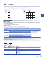
4.4
Arrays
An array represents a consecutive accumulation of the same data type labels, under the same name.
Arrays can be defined by the elementary data types or structures or function blocks.
The maximum number of arrays differs depending on the data types.
One-dimensional array
Two-dimensional array
Label name
Label name Indexes
[0,0]
[0,1]
…
[0,n]
[1,0]
[1,1]
…
…
…
…
…
…
…
[n]
[m,0]
…
[m,n]
[0]
bLabel2
[1]
…
bLabel1
Indexes
4
Definition of arrays
■Array elements
When an array is defined, the number of elements, or the length of array, must be determined. For the range of the number of
elements, refer to the following.
Page 26 Maximum number of array elements
■Definition format
The following table lists definition format examples up to three dimensions.
The range from the array start value to the array end value is the number of elements.
Number of array
dimensions
Format
Remarks
One dimension
Array of elementary data type/structure name (array start value .. array end value)
• For elementary data types:
Page 22 Elementary data type
• For structured data types:
Page 27 Structures
(Definition example) Bit (0..2)
Two dimensions
Array of elementary data type/structure name (array start value .. array end value, array start
value .. array end value)
(Definition example) Bit (0..2, 0..1)
Three dimensions
Array of elementary data type/structure name (array start value .. array end value, array start
value .. array end value, array start value .. array end value)
(Definition example) Bit (0..2, 0..1, 0..3)
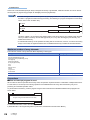
How to use arrays
To identify individual labels of an array, append an index enclosed by "[ ]" after the label name.
For an array with two or more dimensions, delimit indexes in "[ ]" by using "comma (,)".
bLabel1 [0]
Label name
bLabel2 [0,3]
Indexes
Type
Specification example
Remarks
Constant
bLabel1[0]
An integer equal to or greater than 0 can be specified. Decimal constant or hexadecimal constant can
be specified.
Device
bLabel1[D0]
A word device or double-word device can be specified.
Label
bLabel1[uLabel2]
The following data types can be specified.
• Word [unsigned]/bit string [16 bits]
• Double word [unsigned]/bit string [32 bits]
• Word [signed]
• Double word [signed]
Expression
bLabel1[5+4]
Expressions can be specified only in ST language.
4 LABELS
4.4 Arrays
25
Precautions
When a bit of a device/label (example: D0.0) is assigned to bit array in global label, labels and devices can not be used for
the array index in programming (example: bLabel1[D0] cannot be programmed).
• The data storage location becomes dynamic by specifying a label for the array index. This enables arrays to
be used in a program that executes loop processing. The following is a program example that consecutively
stores "1234" in the "uLabel4" array.
bLabel1
INC
wLabel3
K1234
uLabel4[wLabel3]
bLabel2
MOV
• In the case of the ladder diagram, arrays can be used with element numbers omitted. When the element
number is omitted, it is converted to the starting number of the array element. For example, when the label
name you define is "boolAry" and the data type is "bit (0..2,0..2)", then "boolAry[0,0]" and "boolAry" are
treated in the same way.
• A multidimensional array can be specified as setting data of an instruction, function, or function block using
arrays. In that case, the rightmost element in the multidimensional array is treated as the first dimension.
Maximum number of array elements
The maximum number of array elements differs depending on data types.
Data type
Setting range
Bit
Word [Unsigned]/Bit String [16-bit]
Double Word [Unsigned]/Bit String [32-bit]
Word [Signed]
Double Word [Signed]
FLOAT [Single Precision]
Time
Timer
Retentive Timer
Counter
Long Counter
Function Block
1 to 32768
String(32)
1 to 32768 character string length
Precautions
■When an interrupt program is used
When a label or device is specified for the array index, the operation is performed with a combination of multiple instructions.
For this reason, if an interrupt occurs during operation of the label defined as an array, data inconsistency may occur
producing an unintended operation result.
To prevent data inconsistency, create a program using the DI/EI instructions that disables/enables interrupt programs as
shown below.
DI
Program using the label defined as an array
EI
For the DI/EI instructions, refer to the following.
MELSEC iQ-F FX5 Programming Manual (Instructions, Standard Functions/Function Blocks)
26
4 LABELS
4.4 Arrays
■Array elements
When accessing the element defined in an array, access it within the range of the number of elements.
If a constant out of the range defined for the array index is specified, a compile error will occur.
If the array index is specified with data other than a constant, a compile error will not occur. The processing will be performed
by accessing another label area or latch label area.
4.5
Structures
A structure is a data type that includes different labels. Structures can be used in all POUs.
Each member (label) included in a structure can be defined even when the data types are different.
Creating structures
4
To create a structure, first create the configuration of the structure, and define members for the created structure.
Structure
Member (Label 1)
Member (Label 2)
Member (Label 3)
Member (Label 4)
How to use structures
To use structures, register the label with the defined structure as a new data type.
To specify each member, append an element name after the structure label name with "period (.)" as a member name.
Ex.
When using the member of a structure
stLabel1 . bLabel1
Member name
Structure label name
• When labels are registered by defining multiple data types in a structure and used in a program, the order
the data is stored after converted is not the order the data types were defined. When programs are
converted using the engineering tool, labels are classified into type and data type, and then assigned to the
memory (memory assignment by packing blocks).
GX Works3 Operating Manual
• If a member of a structure is specified in an instruction operand that uses control data (series of consecutive
devices from the operand used by the instruction), the control data is assigned to members of the structure
by the order they are stored in memory, not the order the members are defined.
4 LABELS
4.5 Structures
27
Arrays of structures
Structures can also be used as arrays.
Structure label [1]
Structure label [2]
Structure label [3]
Structure label [4]
Member (Label 1)
Member (Label 1)
Member (Label 1)
Member (Label 1)
Member (Label 2)
Member (Label 2)
Member (Label 2)
Member (Label 2)
Member (Label 3)
Member (Label 3)
Member (Label 3)
Member (Label 3)
Member (Label 4)
Member (Label 4)
Member (Label 4)
Member (Label 4)
When a structure is declared as an array, append an index enclosed by "[ ]" after the structure label name.
The array of structure can be specified as arguments of functions and function blocks.
Ex.
When using an element of the structured array
stLabel [0] . bLabel1
Member name
Indexes
Structure label name
Data types that can be specified
The following data types can be specified as a member of a structure.
• Elementary data type
• Pointer type
• Arrays
• Other structures
Structure types
The following data types are defined as a structure beforehand.
Type
Reference
Timer type
Page 22 Data Type
Retentive Timer type
Counter type
Long Counter type
28
4 LABELS
4.5 Structures
4.6
Constant
Types of constants
The following table shows the expressions for setting a constant to a label.
Applicable data type
Type
Expression
Example
Bit
Boolean data
Input "TRUE" or "FALSE".
TRUE, FALSE
Binary
Append "2#" in front of a binary number.
2#0, 2#1
Octal
Append "8#" in front of an octal number.
8#0, 8#1
Decimal
Directly input a decimal number, or append "K" in front of a
decimal number.
0, 1, K0, K1
Hexadecimal
Append "16#" or "H" in front of a hexadecimal number.
16#0, 16#1, H0, H1
Binary*1
Append "2#" in front of a binary number.
2#0010, 2#01101010,
2#1111_1111
Append "8#" in front of an octal number.
8#0, 8#337, 8#1_1
Directly input a decimal number or append "K" in front of a
decimal number.
123, K123, K-123,
12_3
Hexadecimal*1
Append "16#" in front of a hexadecimal number.
Or append "H" in front of a value.
16#FF, HFF, 16#1_1
Real number*1
Directly input a real number, or append "E" in front of a real
number.
2.34, E2.34, E-2.34,
3.14_15
Real number
(exponent
expression)
Append "E" in front of an exponent expression or a real number.
Append "+" in front of exponent part.
1.0E6, E1.001+5
• Word [Unsigned]/Bit String [16-bit]
• Double Word [Unsigned]/Bit String [32bit]
• Word [Signed]
• Double Word [Signed]
FLOAT [Single Precision]
Octal*1
Decimal
*1
String(32)
Character string
Enclose a character string with single quotations (').
'ABC'
Time
Time
Append "T#" in front.
T#1h,
T#1d2h3m4s5ms
*1
4
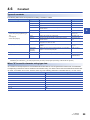
In the binary notation, the octal notation, the decimal notation, the hexadecimal notation, and the real number notation, values can be
delimited by an underscore (_) to make programs easy to read. (In the program processing, underscores are ignored.)
When "$" is used in character string type data
"$" is used as an escape sequence. Two hexadecimal numbers after "$" are recognized as an ASCII code, and characters
corresponding to the ASCII code are inserted in the character string. If no ASCII code for the two hexadecimal numbers after
"$" exists, a conversion error occurs. However, when any of the following characters is described after "$", no error occurs.
Expression
Symbol that is used in character string, or printer code
$$
$
$'
'
$''
''
$L or $l
Line feed
$N or $n
Newline
$P or $p
Page (form feed)
$R or $r
Return
$T or $t
Tab
4 LABELS
4.6 Constant
29
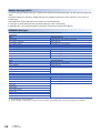
4.7
Precautions
Functions with limitations
In the following functions, there is a limitation on label use.
Item
Description
Trigger of an event execution type program
Labels cannot be used. Consider taking the following measures.
• Use devices.
• Define a label to be used as a global label and assign devices to the global label.
Intelligent function module refresh setting
Labels cannot be used. Consider taking the following measures.
• Use devices.
■Defining and using a global label with a device assigned
Define a global label following the procedure below, and use it when the functions having restriction on the use of labels are
executed.
Since the device area in the device/label memory is used, reserve device area capacity. (The label area is not consumed.)
1.
Reserve the device area to be used.
CPU Parameter Memory/Device Setting Device/Label Memory Area Capacity Setting
2.
3.
Define a label as a global label, and assign a device manually.
Use the label defined in step 2 for the functions having no restrictions on the use of labels. Use the device assigned to
the label for the function having restrictions on the use of labels.
■Copying the label data into a specified device
Copy the label data into a specified device following the procedure below, and use the copy-target device.
Since the device area in the device/label memory is used, reserve device area capacity.
1.
Reserve the device area to be used.
CPU Parameter Memory/Device Setting Device/Label Memory Area Capacity Setting
2.
Create a program using the label. The following is the program example for copying the data. (The data logging function
uses the data in udLabel1.)
SM400
DMOV
3.
udLabel1
D0
Use the device where the data has been transferred in step 2 for the function having restrictions on the use of labels. (In
the program example in step 2, use D0.)
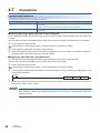
When copying a value of a label to another device by a transfer instruction, note that the number of program
steps increases. In addition, when adding a transfer instruction on a program, consider execution timing of the
function to be used.
30
4 LABELS
4.7 Precautions
Precautions for creating programs
When specifying a label as an operand used in instructions, match the data type of the label with that of the operand. In
addition, when specifying a label as an operand used in instructions that control continuous data, specify the data range used
in instructions within the data range of the label.
Ex.
SFT(P) instruction
SFT
bLabel[0]
SFTP
bLabel[1]
To shift the bits correctly, specify the array of a bit type label.
4
or
SFT
wLabel1.0
SFTP
wLabel1.1
Specify the bit number of a word type label.
Ex.
SFR(P) instruction
Start device number of search range
wLabel1[0]
10
wLabel1[1]
500
123
-123
Data matched
Search range :
(n) points
20
123
wLabel1[n]
Specify a label which has a larger data range than the search range (n) points.
Limitations on label names
Label names have the following limitations:
• A label name must start with a nonnumeric character or underscore (_). It cannot start with a number.
• Reserved words cannot be used as label names.
For details of reserved words, refer to the following.
GX Works3 Operating Manual
4 LABELS
4.7 Precautions
31
5
LADDER DIAGRAM
Ladder diagram is a language that describes the sequence control by indicating logical operations consisting of "AND" or
"OR" with combinations of series connections and parallel connections in a ladder consisting of contacts and coils.
5.1
Configuration
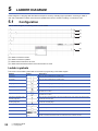
With the ladder diagram, the following ladder can be created.
(1)
(2)
(3)
(4)
(5)
(1) A ladder consists of contacts and coils
(2) A ladder connected in series
(3) A ladder connected in parallel
(4) A ladder where instructions are used
(5) A ladder where standard functions and function blocks are used
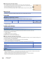
Ladder symbols
This section shows ladder symbols that can be used for programming in the ladder diagram.
Element
32
Symbol
Description
NO contact
Turns on when a specified device or label is ON.
NC contact
Turns on when a specified device or label is OFF.
Rising edge
Turns on at the rising edge (OFF to ON) of a specified device or label.
Falling edge
Turns on at the falling edge (ON to OFF) of a specified device or label.
Negated rising edge
Turns on when a specified device or label is OFF or ON, or at the falling edge (ON to OFF) of a
specified device or label.
Negated falling edge
Turns on when a specified device or label is OFF or ON, or at the rising edge (OFF to ON) of a
specified device or label.
Conversion of operation result
to leading edge pulse
Turns on at the rising edge (OFF to ON) of an operation result. Turns off when the operation result
is other than the rising edge.
Conversion of operation result
to trailing edge pulse
Turns on at the falling edge (ON to OFF) of an operation result. Turns off when the operation result
is other than the falling edge.
Inverting the operation result
Inverts the operation just before this instruction.
Coil
Outputs an operation result to a specified device or a label.
Instruction
Executes an instruction specified in [ ].
Turn-back
Turns back a circuit by creating a turn source symbol and a turn destination symbol when the
number of contacts exceeds the number of contacts that can be created in one line.
5 LADDER DIAGRAM
5.1 Configuration
Element
Symbol
Description
Function
Executes a function.
• How to create functions (GX Works3 Operating Manual)
• Standard function (MELSEC iQ-F FX5 Programming Manual (Instructions, Standard
Functions/Function Blocks))
Function block
Executes a function block.
• How to create function blocks (GX Works3 Operating Manual)
• Standard function blocks (MELSEC iQ-F FX5 Programming Manual (Instructions, Standard
Functions/Function Blocks))
• Module function blocks (MELSEC iQ-F FX5 CPU Module Function Block Reference)
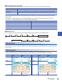
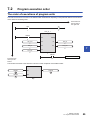
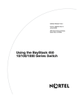
Program execution order
The program is executed in order of the following numbers.
X1
1
X2
2
X3 3
X4
5
Y1
4
Y2
6
5
When executing the program above, Y1 and Y2 turn on corresponding to turning ON or OFF of X1 to X4 as shown below.
X1
X2
X3
X4
Y1
Y2
ON
OFF
ON
OFF
ON
OFF
ON
OFF
ON
OFF
ON
OFF
5 LADDER DIAGRAM
5.1 Configuration
33
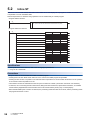
5.2
Inline ST
Inline ST is a function that creates, edits and monitors inline ST box that displays an ST program in a cell of an instruction that
is equivalent to a coil in the ladder editor.
Numerical operations or character string operations can be created easily in a ladder program.
• Program with the inline ST
X0
1
2
W0:=K0;
W0:=(D0+D1+D2+D3+D4+D5+D6+D7+D8+D9+D10+D11)/K12;
• Program without the inline ST
X0
/
MOV
K0
W0
+
D0
W0
+
D1
W0
+
D2
W0
+
D3
W0
+
D4
W0
+
D5
W0
+
D6
W0
+
D7
W0
+
D8
W0
+
D9
W0
+
D10
W0
+
D11
W0
W0
K12
W0
Specifications
For the specifications of the inline ST, refer to the ST language specifications.
Page 36 ST LANGUAGE
Precautions
• Only one inline ST can be created in one line of a ladder program.
• Creating both a function block and an inline ST box in one line of a ladder program is impossible.
• Creating an inline ST box in a position of an instruction that is equivalent to a contact creates an inline ST box in a position
of an instruction that is equivalent to a coil.
• The maximum number of characters that can be input in an inline ST is 2048. (Line feed is counted as one character.)
• In inline ST, do not use rising execution instructions, falling execution instructions, special timer instructions, or standard
function blocks (edge detection function blocks and counter function blocks) as they may not work property.
• When the RETURN syntax is used in an inline ST, the processing inside the inline ST box ends, and the processing inside
the program block does not end.
34
5 LADDER DIAGRAM
5.2 Inline ST
5.3
Statements and Notes
In a ladder program, statements and notes can be displayed.
Statements
By using statements, users can append comments to circuit blocks. Appending statements makes the processing flow easy to
understand.
Statements include line statements, P statements, and I statements.
A line statement can be displayed on a tree view of the Navigation window.
■Line statement
A comment is appended to a ladder block as a whole.
■P statement
A comment is appended to a pointer number.
5
■I statement
A comment is appended to an interrupt pointer number.
Notes
By using notes, users can append comments to coils and instructions in a program.
Appending notes makes the details of coils and application instructions easy to understand.
Types of statements and notes
"PLC" and "Peripheral" are the types of statements and notes.
Type
Type
Description
PLC
•
•
•
•
Line statement
P statement
I statement
Note
Statements and notes can be stored on the CPU module.
PLC statement uses the following number of steps. (When all the characters are input in onebyte characters. Decimal fraction is rounded up.)
• Without character: 3 steps
• With character: 4 + (Number of characters + 2 + 14) / 5 + Number of characters (steps)
Peripheral
•
•
•
•
Line statement
P statement
I statement
Note
Statements and notes cannot be stored on the CPU module. (Only the position information can
be stored.)
Statements and notes must be saved on a peripheral device.
One statement or note line uses one step.
A * symbol is prefixed to the entered text automatically.
5 LADDER DIAGRAM
5.3 Statements and Notes
35
6
ST LANGUAGE
The ST language is one of the languages supported by IEC 61131-3, the international standard that defines the description
methods for logic. ST language is a text programming language with a grammatical structure similar to C language. ST
language is suitable for programming some complicated processing that cannot be easily described using ladder diagram.
ST language supports control syntaxes, operational expressions, function blocks (FBs), and functions (FUNs). Therefore, the
following description can be made.
Ex.
Control syntaxes using selective branches with conditional statements and repetition by iteration statements
(* Control conveyors of Line A to C. *)
CASE Line OF
1: Start_switch := TRUE; (* The conveyor starts. *)
2: Start_switch := FALSE; (* The conveyor stops. *)
3: Start_switch := TRUE; (* The conveyor stops with an alarm. *)
ELSE Alarm_lamp := TRUE;
END_CASE;
IF Start_switch = TRUE THEN (* The conveyor starts and performs processing 100 times. *)
FOR Count := 0
TO 100
BY 1 DO
Count_No := Count_No +1;
END_FOR;
END_IF;
Ex.
Expressions using operators (such as *, /, +, -, <, >, and =)
D0 := D1* D2 + D3 / D4 -D5;
IF D0 > D10 THEN
D0 := D10;
END_IF;
Ex.
Calling a defined function block
//FB data name
: LINE1_FB
//Input variable
: I_Test
//Output variable
: O_Test
//Input/output variable : IO_Test
//FB label name
: FB1
FB1(I_Test :=D0,O_Test => D1,IO_Test := D100);
Ex.
Calling a standard function
(* Convert BOOL data type to INT/DINT data type. *)
wLabel2 := BOOL_TO_INT (bLabel1);
36
6 ST LANGUAGE
6.1
Configuration
Operators and syntaxes are used for programing in ST language.
intV2 := ABS(intV1);
Assignment statement
IF M1 THEN
btn01 := TRUE;
ELSE
btn01 := FALSE;
END_IF;
Conditional statement
Output_ENO := ENEG(btn01,Input1);
Calling a function
LadderFBInstance(Input1:=bool1,Input2:=bool2,Input3:=bool3);
(* user function block *)
Calling a function block
A statement must end with ";" (semicolon).
intV1 := 0 ;
intV2 := 2 ;
End of the statement
6
Spaces, tabs, and line feeds can be inserted anywhere between an operator and data.
Space
intV1 := 0 ;
intV2 :=
2;
Tab
Line feed
Comments can be inserted in a program.
intV1 := 0;
(* Substitution *)
intV2 := 2;
Comment
Constituent elements of a program
A ST program consists of the following elements.
Item
Example
Reference
Delimiter
;, ( )
Page 38 Delimiter
+, -, <, >, =
Page 38 Operator
Syntax
IF, CASE, WHILE, RETURN
Page 39 Syntax
Device
X0, Y10, M100
MELSEC iQ-F FX5 User's Manual (Application)
Data type
BOOL, DWORD
Page 22 Data Type
Function
ADD, REAL_TO_STRING_E
MELSEC iQ-F FX5 Programming Manual
(Instructions, Standard Functions/Function Blocks)
123, 'abc'
Page 46 Constant
Label
Switch_A
Page 46 Label and device
Comment
(* Turn ON *), //Turn ON, /*Turn ON*/
Page 48 Comment
Other symbols
One-byte space, line feed code, tab code
Operator
Reserved word
Constant
• Use one-byte delimiters, operators, and reserved words.
• For details of reserved words, refer to the following.
GX Works3 Operating Manual
6 ST LANGUAGE
6.1 Configuration
37
Delimiter
The following delimiters are provided in ST language for clarifying the program structure.
Symbol
Description
()
Parenthesized
[]
Specification of an array element
. (period)
Specification of members of the structure or function block
, (comma)
Separation of arguments
: (colon)
Device type specifier
; (semicolon)
End of a sentence
' (single quotation mark)
Description of a character string
.. (two periods)
Specification of an integer range
Operator
The following shows the operators used in a ST program and the target data types and operation result data types for each
operator.
Operator
Target data type
Operation result type
*, /, +, -
ANY_NUM
ANY_NUM
<, >,<=, >=, =, <>
ANY_SIMPLE
Bit
MOD
ANY_INT
ANY_INT
AND, &, XOR, OR, NOT
ANY_BIT
ANY_BIT
**
ANY_REAL (Base)
ANY_NUM (Exponent)
ANY_REAL
The following table shows the priorities of the operators.
Operator
Description
Example
Priority
()
Parenthesized expression
(2+3)*(4+5)
1
Function ( )
Argument of a function
CONCAR('AB','CD')
2
**
Exponentiation
3.0**4
3
-
Inversion of sign
-10
4
NOT
Bit type complement
NOT TRUE
*
Multiplication
10 * 20
/
Division
20 / 10
MOD
Modulus operation
17 MOD 10
+
Addition
1.4 + 2.5
-
Subtraction
3-2
5
6
<, >, <=, =>
Comparison
10 > 20
7
=
Equality
T#26h = T#1d2h
8
<>
Inequality
8#15 <> 13
&, AND
Logical AND
TRUE AND FALSE
XOR
Exclusive OR
TRUE XOR FALSE
10
OR
Logical OR
TRUE OR FALSE
11
9
• If an expression includes multiple operators with the same priority, the operation is performed from the leftmost operator.
• Up to 1024 operators can be used in one statement.
38
6 ST LANGUAGE
6.1 Configuration
Syntax
The following table shows the types of statements that can be used in a ST program.
Item
Description
Reference
Assignment statement
Assignment statement
Page 39 Assignment statement
Sub-program control statement
Function block call statement, function call statement
Page 40 Sub-program control statement
RETURN statement
Conditional statement
IF statement (IF, IF...ELSE, IF...ELSIF)
Page 41 Conditional statement
CASE statement
Iteration statement
FOR statement
Page 42 Iteration statement
WHILE statement
REPEAT statement
EXIT statement
Write statements using half width characters.
Assignment statement
Format
Description
Example
<Left side> := <Right side> ;
The assignment statement assigns the result of the right side expression to the label or device of
the left side.
The result of the right side expression and the data type of the left side need to be the same data
type.
intV1 := 0;
intV2 := 2;
6
When an array type label or a structure label is used, check the data types of the left side and right side of the assignment
statement.
When an array type label is used, the data type and the number of elements need to be the same for the left side and right
side. Do not specify elements.
Ex.
intAry1 := intAry2;
When a structure label is used, the data type needs to be the same for the left side and right side.
Ex.
dutVar1 := dutVar2;
■Automatic conversion of data types
In the ST language, if a different data type is assigned or a different arithmetic operation is described, the data type may be
automatically converted.
Ex.
Example of automatic conversion
dintLabel1 := intLabel1;
// Assignment statement : Automatically convert the INT type variable (intLabel1) to a DINT type variable,
and assign it the DINT type variable (dintLabel1).
dintLabel1 := dintLabel2 + intLabel1;
// Arithmetic operation expression : Automatically convert the INT type variable (intLabel1) to a DINT type
variable, and perform DINT type addition.
Type conversion is performed in an assignment statement, input argument pass to a function block and function (VAR_INPUT
part), and an arithmetic operation.
6 ST LANGUAGE
6.1 Configuration
39
To avoid the deletion of the data during type conversion, only conversion from smaller type to larger type is performed. Of the
elementary data types, type conversion is performed only for the following data types among basic data types are the targets
of a type conversion.
Data type
Description
Word [Signed]
In the case of a double word [signed] after conversion, the conversion is automatically made into a value
with a sign extension.
In the case of a single-precision real, an automatic conversion is made into the same value as the integer
before the conversion.*1
Word [Unsigned]/Bit String [16-bit]
In the case of a double word [unsigned]/bit string [32 bits] or a double word [signed] after conversion, an
automatic conversion is made into to a value with a zero extension.*2
In the case of a single-precision real, an automatic conversion is made into the same value as the integer
before the conversion.*1
*1
*2
When the data of 16 bits (a word [signed] or a word [unsigned]/bit string [16 bits]) is transferred to an input argument of the data type
ANY_REAL, an automatic conversion is made into a single- precision real.
When the data of a word [unsigned]/bit string [16 bits] is transferred to an input argument of ANY32, an automatic conversion is made
into a double word [unsigned]/bit string [32 bits].
For data types that are not described above, use the type conversion function.
Since type conversion is not performed in the following cases, use the type conversion function.
• Type conversion between integer-data types with different signs
• Type conversion between the data types by which the data is deleted
For the precautions for assigning the result of an arithmetic operation, refer to the following.
Page 43 When an assigned arithmetic operation is used
Sub-program control statement
■Function block call statement
Format
Description
Instance name(Input variable1:= Variable1, ... Output
variable1: => Variable2, ...);
Enclose the assignment statement that assigns variables to the input variable and output
variable by "( )" after the instance name.
When using multiple variables, delimit the assignment statement by "," (comma).
Instance name.Input variable1:= Variable1;
:
Instance name();
Variable2:= Instance name.Output variable1;
List the assignment statement that assigns variables to the input variable and output variable
before and after a function block call statement.
The following table shows the symbols used for arguments in a function block call statement and available formats.
Type
Description
Attribute
Symbol
Available formats
VAR_INPUT
Input variable
N/A, or RETAIN
:=
All formats
Variable only
VAR_OUTPUT
Output variable
N/A, or RETAIN
=>
VAR_IN_OUT
Input/Output variable
N/A
:=
All formats
VAR_PUBLIC
External variable
N/A, or RETAIN
Cannot be specified
The execution result of the function block is stored by assigning the output variable that is specified by adding "." (period) after
the instance name to the variable.
40
Function block
FB definition
Example
Calling a function block with one input variable and one
output variable
FB name: FBADD
FB instance name: FBADD1
Input variable1: IN1
Output variable1: OUT1
FBADD1(IN1:=Input1);
Output1:=FBADD1_OUT1;
Calling a function block with three input variables and two
output variables
FB name: FBADD
FB instance name: FBADD1
Input variable1: IN1
Input variable2: IN2
Input variable3: IN3
Output variable1: OUT1
Output variable2: OUT2
FBADD1(IN1:=Input1, IN2:=Input2, IN3:=Input3);
Output1:=FBADD1_OUT1;
Output2:=FBADD1_OUT2;
6 ST LANGUAGE
6.1 Configuration
■Function call statement
Format
Description
Function name(Variable1, Variable2, ...);
Enclose an argument by "()" after the function name.
When using multiple arguments, delimit them by "," (comma).
Assigning to variables stores the execution result of the function.
Function
Example
Calling a function with one input variable (Example: ABS)
Outout1 := ABS(Input1);
Calling a function with three input variables (Example:
MAX)
Outout1 := MAX(Input1, Input2, Input3);
Calling a function with EN/ENO (excluding standard
functions) (Example: MAX_E)
Output1 := MAX_E(boolEN, boolENO, Input1, Input2, Input3);
Calling a standard function (Example: MOV)
boolENO := MOV(boolEN, Input1, Output1);
(The execution result of the function is ENO and the first argument (Variable1) is EN.)
A user-defined function that does not return a value and a function that includes a VAR_OUTPUT variable in the argument of
a call statement can be executed as a statement by adding a semicolon (;) at the end.
■RETURN statement
Syntax
Format
Description
Example
■RETURN
RETURN;
The RETURN statement is used to end a program, function
block, or function in the middle of processing.
When the RETURN statement is used in a program, the
processing jumps to the next step after the last line of the
program.
When the RETURN statement is used in a function block, the
processing is returned from the function block.
When the RETURN statement is used in a function, the
processing is returned from the function.
One pointer type label is used by the system for one RETURN
statement.
IF bool1 THEN
RETURN;
END_IF;
6
A user-defined function that does not return a value and a function that includes a VAR_OUTPUT variable in the parameter of
a call statement can be executed as a statement by adding a semicolon (;) at the end.
Conditional statement
Syntax
Format
Description
Example
■IF
IF <Boolean expression> THEN
<Statement> ;
END_IF;
The statement is executed when the value of Boolean
expression (conditional expression) is TRUE. The statement is
not executed if the value of Boolean expression is FALSE.
Any expression that returns TRUE or FALSE as the result of the
Boolean operation with a single bit type variable status, or a
complicated expression that includes many variables can be
used for the Boolean expression.
IF bool1 THEN
intV1:=intV1+1;
END_IF;
■IF...ELSE
IF <Boolean expression> THEN
<Statement 1> ;
ELSE
<Statement 2> ;
END_IF;
Statement 1 is executed when the value of Boolean expression
(conditional expression) is TRUE.
Statement 2 is executed when the value of Boolean expression
is FALSE.
IF bool1 THEN
intV3:=intV3+1;
ELSE
intV4:=intv4+1;
END_IF;
■IF...ELSIF
IF <Boolean expression 1> THEN
<Statement 1> ;
ELSIF <Boolean expression 2> THEN
<Statement 2> ;
ELSIF <Boolean expression 3> THEN
<Statement 3> ;
END_IF;
Statement 1 is executed when the value of Boolean expression
(conditional expression) 1 is TRUE. Statement 2 is executed
when the value of Boolean expression 1 is FALSE and the
value of Boolean expression 2 is TRUE.
Statement 3 is executed when the value of Boolean expression
1 and 2 are FALSE and the value of Boolean expression 3 is
TRUE.
IF bool1 THEN
intV1:=intV1+1;
ELSIF bool2 THEN
intv2:=intV2+2;
ELSIF bool3 THEN
intV3:=intV3+3;
END_IF;
6 ST LANGUAGE
6.1 Configuration
41
Syntax
Format
Description
■CASE
CASE <Integer expression> OF
<Integer selection 1> :
<Statement 1> ;
<Integer selection 2> :
<Statement 2> ;
<Integer selection n> :
<Statement n> ;
ELSE
<Statement n+1> ;
END_CASE;
When the statement that has the integer selection value that
matches with the value of the integer expression (conditional
expression) is executed, and if no integer selection value
matches with the expression value, the statement that follows
the ELSE statement is executed.
The CASE statement is used to execute a conditional statement
based on a single integer value or an integer value as the result
of a complicated expression.
Example
CASE intV1 OF
1:
bool1:=TRUE;
2:
bool2:=TRUE;
ELSE
intV1:=intV1+1;
END_CASE;
Iteration statement
42
Syntax
Format
Description
Example
■FOR
FOR <Repeat variable initialization>
TO <Last value>
BY <Incremental expression> DO
<Statement> ;
END_FOR;
The FOR...DO statement first initializes the data used as a
repeat variable.
An addition or subtraction is made to the initialized repeat
variable according to the incremental expression. One or more
statements from DO to END_FOR are repeatedly executed until
the final value is exceeded.
The repeat variable at the end of the FOR...DO syntax is the
value at end of the execution.
FOR intV1:=0
TO 30
BY 1 DO
intV3:=intV1+1;
END_FOR;
■WHILE
WHILE <Boolean expression> DO
<Statement> ;
END_WHILE;
The WHILE...DO statement executes one or more statements
while the value of Boolean expression (conditional expression)
is TRUE.
The Boolean expression is evaluated before the execution of
the statement. If the value of Boolean expression is FALSE, the
statement in the WHILE...DO statement is not executed. Since
a return result of the Boolean expression in the WHILE
statement requires only TRUE or FALSE, any Boolean
expression that can be specified in the IF conditional statement
can be used.
WHILE intV1=30 DO
intV1:=intV1+1;
END_WHILE;
■REPEAT
REPEAT
<Statement> ;
UNTIL <Boolean expression>
END_REPEAT;
The REPEAT...UNTIL statement executes one or more
statements while the value of Boolean expression (conditional
expression) is FALSE.
The Boolean expression is evaluated after the execution of the
statement. If the value of Boolean expression is TRUE, the
statement in the REPEAT...UNTIL statement are not executed.
Since a return result of the Boolean expression in the REPEAT
statement requires only TRUE or FALSE, any Boolean
expression that can be specified in the IF conditional statement
can be used.
REPEAT
intV1:=intV1+1;
UNTIL intV1=30
END_REPEAT;
■EXIT
EXIT;
The EXIT statement is used only in an iteration statement to
end the iteration statement in the middle of processing.
When the EXIT statement is reached during execution of the
iteration loop, the iteration loop processing after the EXIT
statement is not executed. The processing continues from the
line after the one where the iteration statement is ended.
FOR intV1:=0
TO 10
BY 1 DO
IF intV1>10 THEN
EXIT;
END_IF;
END_FOR;
6 ST LANGUAGE
6.1 Configuration
Precautions
■When an assignment statement is used
• The maximum number of character strings that can be assigned is 255. If 256 or more character strings are assigned, a
conversion error occurs.
• Contacts and coils of the timer type or counter type cannot be used for the left side of an assignment statement.
• The instance of a function block cannot be used for the left side of an assignment statement. Use input variables, input/
output variables, and external variables of the instance for the left side of an assignment statement.
■When an assigned arithmetic operation is used
When an arithmetic operation result is assigned to a variable of the larger data type, convert the variable of the arithmetic
operation to the data type of the left side in advance and execute the operation.
Ex.
When an arithmetic operation result of 16-bit data (INT type) is assigned to 32-bit data (DINT type)
varDint1 := varInt1 * 10;
// VarInt1 is a INT type variable, and varDint1 is a DINT type variable.
The arithmetic operation result is the same data type as that of the input operand. Thus, in the case of the above program,
when the operation result of varInt1 * 10 exceeds the range of the INT type (-32768 to +32767), an overflow or underflow
6
result is assigned to varDint1.
In this case, convert the operand of the operational expression to the data type of the left side in advance and execute the
operation.
varDint2 := INT_TO_DINT(varInt1); // INT type variable is converted to DINT type variable.
varDint2 := varDint2 * 10;
// DINT type multiplication is performed, and the operation result is assigned.
■Using the operator "-" for sign inversion in an arithmetic operation
When the operator "-" is used to invert the sign of the minimum value of a data type, the minimum value evaluates to the same
value.
For example, -(-32768), where the operator "-" is used with the minimum value of INT type, evaluates to -32768. Thus, an
unintended result may be produced if the operator "-" is used to invert the sign of a variable whose data type will be
automatically converted.
Ex.
When the value of varInt1 (INT type) is -32768, and the value of varDint1 (DINT type) is 0.
varDint2 := -varInt1 + varDint1;
In the example above, the value of (-varInt1) evaluates to -32768 and -32768 is assigned to varDint2.
When using the operator "-" to invert the sign of a variable in an arithmetic operation, perform automatic conversion of the
data type of the variable before the arithmetic operation. Alternatively, avoid using the operator "-" for sign inversion in the
program.
Ex.
Performing automatic conversion of the data type before an arithmetic operation
varDint3 := varInt;
varDint2 := -varDint3 + varDint1;
Ex.
Avoiding the use of the operator "-" for sign inversion
varDint2 := varDint1 - varInt1;
6 ST LANGUAGE
6.1 Configuration
43
■When a bit type label is used
Once the Boolean expression (conditional expression) is satisfied in a conditional statement or an iteration statement, the bit
type label that is turned ON in <Statement> is always set to ON.
Ex.
Program whose bit type label is always set to on
ST program
Ladder program equivalent to ST program
IF bLabel1 THEN
bLabel2 := TRUE;
END_IF;
bLabel1
SET
bLabel2
To avoid the bit device to be always set to ON, add a program to turn OFF the bit type label as shown below.
Ex.
Program to avoid the bit type label to be always set to ON
ST program*1
Ladder program equivalent to ST program
IF bLabel1 THEN
bLabel2 := TRUE;
ELSE
bLabel2 := FALSE;
END_IF;
*1
bLabel1
bLabel2
The above program can also be described as follows.
bLabel2 := bLabel1;
or
OUT(bLabel1,bLabel2);
However, when the OUT instruction is used in <Statement>, the program status becomes the same as the program whose bit type label
is always set to on.
■When a timer function block or counter function block is used
Boolean expression (conditional expression) in a conditional statement differs for the execution conditions of the timer
function block or counter function block.
Ex.
When a timer function block is used
Program before change
IF bLabel1 THEN
TIMER_100_FB_M_1(Coil:=bLabel2,Preset:=wLabel3,ValueIn:=wLabel4,ValueOut=>wLabel5,Status=>bLabel6);
END_IF;
(* When bLabel1 = on and bLabel2 = on, counting starts.
*)
(* When bLabel1 = on and bLabel2 = off, the counted value is cleared.
*)
(* When bLabel1 = off and bLabel2 = on, counting stops. The counted value is not cleared. *)
(* When bLabel1 = off and bLabel2 = off, counting stops. The counted value is not cleared. *)
Program after change
TIMER_100_FB_M_1(Coil:=(bLabel1&bLabel2),Preset:=wLabel3,ValueIn:=wLabel4,ValueOut=>wLabel5,Status=>bLabel6);
When a counter function block is used
Program before change
IF bLabel1 THEN
COUNTER_FB_M_1(Coil:=bLabel2,Preset:=wLabel3,ValueIn:=wLabel4,ValueOut=>wLabel5,Status=>bLabel6);
END_IF;
(* When bLabel1 = on and bLabel2 = on/off, the value is incremented by 1. *)
(* When bLabel1 = off and bLabel2 = on/off, the value is not counted.
*)
(* The counting operation does not depend on the on/off status of bLabel1. *)
Program after change
COUNTER_FB_M_1(Coil:=(bLabel1&bLabel2),Preset:=wLabel3,ValueIn:=wLabel4,ValueOut=>wLabel5,Status=>bLabel6);
44
6 ST LANGUAGE
6.1 Configuration
An error occurs when the program before change is used since the statement related to the timer or counter is not executed
when the selection statement is not satisfied.
When the timer or counter is operated according to the AND condition of bLabel1 and bLabel2, do not use any control
statement, just use a function block only.
Using the program after change operates the timer and counter.
■When the FOR...DO statement is used
• Structure members and array elements cannot be used as repeat variables.
• Match the type used for a repeat variable with the types of <Last value expression> and <Incremental expression>.
• <Incremental expression> can be omitted. When omitted, <Incremental expression> is treated as 1 and executed.
• When 0 is assigned to <Incremental expression>, the statements after the FOR syntax may not be executed or the
processing goes into an infinite loop.
• In the FOR...DO syntax, the counting process of repeat variables is executed after the execution of <Statement> in the
FOR syntax. If the count is greater than the maximum value or smaller than the minimum value of the data type of the
repeat variable, the processing goes into an infinite loop.
■When a rising execution instruction or a falling execution instruction is used
Shown here is the operation when a rising execution instruction or an fall execution instruction is used in an IF statement or a
CASE statement.
Condition
6
Result of operation
Conditional
expression of an IF
statement or a
CASE statement
Condition to
execute an
instruction (EN)
Result of the ON/
OFF judgment of
the instruction at
the time of the
previous scan
Result of the ON/
OFF judgment of
the instruction
Rising execution
instruction
Falling execution
instruction
Agreement of TRUE or
CASE
TRUE
ON
ON
Not executed
Not executed
OFF
ON
Executed
Not executed
FALSE
ON
OFF
Not executed
Executed
OFF
OFF
Not executed
Not executed
TRUE
ON
OFF
Not executed
Not executed*1
OFF
OFF
Not executed
Not executed
ON
OFF
Not executed
Not executed*1
OFF
OFF
Not executed
Not executed
Disagreement of FALSE
or CASE
FALSE
*1
This is a fall (ON to OFF), but the instruction is not executed because the condition in the IF statement or the CASE statement is not
satisfied.
Ex.
When the PLS instruction (rising execution instruction) is used in an IF statement
IF bLabel0 THEN
PLS(bLabel1,bLabel10);
END_IF;
(1) If bLabel0 = OFF (the condition expression in the IF statement is
FALSE), the ON/OFF judgment result is OFF. The PLS
instruction is not executed. (bLabel10 = OFF does not change.)
(2) If bLabel0 = ON (the condition expression in the IF statement is
TRUE) and bLabel1 = OFF (the condition for executing the
instruction is OFF), the ON/OFF judgment result is OFF. The PLS
instruction is not executed. (bLabel10 = OFF does not change.)
(3) If bLabel0 = ON (the condition expression in the IF statement is
TRUE) and bLabel1 = ON (the condition for executing the
instruction is ON), the ON/OFF judgment result is OFF to ON (the
condition for a rise is satisfied). The PLS instruction is executed.
(bLabel10 turns ON for once scan only.)
ON
bLabel0
OFF
ON
bLabel1
ON/OFF
judgment
result
OFF
ON
OFF
(1)
bLabel10
ON
OFF
(2)
(3)
ON
1 scan
6 ST LANGUAGE
6.1 Configuration
45
■When a master control instruction is used
Shown here is the operation when the master control is OFF.
• The statement in a selection statement (an IF statement or a CASE statement) or in a iteration statement (a FOR
statement, a WHILE statement, or a REPEAT statement) is not processed.
• Outside of a selection statement or a iteration statement, assignment statement is not processed and statement other than
assignment statement is not executed.
Ex.
A statement in a selection statement (IF statement)
MC(M0,N1,M1); //Master control OFF
IF M2 THEN
M3:=M4;
//No processing is executed when the master control is OFF. So, M3 maintains the value at the time of a previous scan.
END_IF;
M20:=MCR(M0,N1);
Ex.
A statement out of a selection statement or a iteration statement (in the case of a bit assignment statement)
MC(M0,N1,M1); //Master control OFF
M3:=M4;
//No processing is executed when the master control is OFF. So, M3 maintains the value at the time of a previous scan.
M20:=MCR(M0,N1);
Ex.
A statement out of a selection statement or a iteration statement (in the case of an OUT instruction)
MC(M0,N1,M1); //Master control OFF
OUT(M2,M3);
//No execution is made when the master control is OFF.
M20:=MCR(M0,N1);
Constant
Methods for expressing constants
The following table shows the expression methods for setting a constant in a ST program.
Data type
String(32)
STRING
Expressing method
Example
Enclose character strings with single quotation ( ' ).
Stest := 'ABC';
For the expression methods other than the one described the above, refer to the following.
Page 29 Constant
Label and device
Specification method
Labels and devices can be directly described in the ST program. Labels and devices can be used for the left or right side of an
expression or as an argument or return value of a standard function/function block.
For available labels, refer to the following.
Page 21 LABELS
For available devices, refer to the following.
MELSEC iQ-F FX5 User's Manual (Application)
46
6 ST LANGUAGE
6.1 Configuration
■Device expression with type specification
A word device can be used in ST language as an arbitrary data type by adding a device type specifier to its name.
Device type specifier
Data type
Example
Description
N/A
Generic data type ANY16.
When only devices are used in arithmetic operations,
the data type is Word [signed].
However, when the data is specified as a device
without the type specification in the argument part of
FUN/FB, the data type is the one of the argument
definition.
D0
When no type specifier is added to D0
:U
Word [Unsigned]/Bit String [16-bit]
D0:U
The value when D0 is Word [unsigned]/Bit string [16-bit]
:D
Double Word [Signed]
D0:D
The value when D0 and D1 are Double word [signed]
:UD
Double Word [Unsigned]/Bit String [32-bit]
D0:UD
The value when D0 and D1 are Double word [unsigned]/Bit
string [32-bit]
:E
FLOAT (Single Precision)
D0:E
The value when D0 and D1 are single-precision real
numbers
The following shows the devices to which device type specifiers can be added.
• Data register (D)
• Link register (W)
6
• Module access device (U\G)
• File register (R)
■Device specification method
The following methods can be used for specifying a device.
• Indexing
• Bit specification
• Nibble specification
• Indirect specification
For details, refer to the following.
MELSEC iQ-F FX5 User's Manual (Application)
MELSEC iQ-F FX5 Programming Manual (Instructions, Standard Functions/Function Blocks)
Precautions
• The pointer type can be used for ST programs.
• When a value is assigned using nibble specification, use the same data type for the left side and right side of an operation.
Ex.
D0 := K5X0;
In the above case, since K5X0 is the double word type and D0 is the word type, an error occurs in the program.
• When a value is assigned using nibble specification and the data size of the right side is larger than that of the left side,
data is transmitted within the range of the target points of the left side.
Ex.
K5X0 := 2#1011_1101_1111_0111_0011_0001;
In the above case, since the target points of K5X0 is 20, 1101_1111_0111_0011_0001 (20 bits) are assigned to K5X0.
• When the current value (such as TNn) of a counter (C), timer (T), or retentive timer (ST) is used with a type other than Word
[unsigned]/Bit string [16-bit], or when the current value (such as LCNn) of a long counter (LC) is used with a type other than
Double word [unsigned]/Bit string [32-bit], use the type conversion function.
Ex.
varInt := WORD_TO_INT(TN0); (*Use the type conversion function*)
6 ST LANGUAGE
6.1 Configuration
47
Comment
The following table shows the comment formats that can be used in a ST program.
Comment format
Comment
symbol
Description
Example
Single line comment
//
The character strings between the start symbol "//" and the end of the
line are used as a comment.
// Comment
Multiple-line comment
(* *)
The character strings between the start symbol "(*" and the end symbol
"*)" are used as a comment.
Newlines can be inserted in the comment.
■Without newline
(* Comment *)
■With newline
(* Comment in the first line
Comment in the second line *)
/* */
The character strings between the start symbol "/*" and the end symbol
"*/" are used as a comment.
Newlines can be inserted in the comment.
■Without newline
/* Comment */
■With newline
/* Comment in the first line
Comment in the second line */
When the multiple-line comment format is used, do not use end symbols inside comments.
48
6 ST LANGUAGE
6.1 Configuration
7
FBD/LD Language
This is a language that creates a program by wiring blocks for specific processing, variables, and constants along with the
flows of data and signals.
7.1
Configuration
With the FBD/LD language, the following program can be created.
(1) FBD unit
(2) LD unit
(3) Common unit
(6)
(4) Connecting wire
(2)
(5) Connecting point
(5)
(6) Worksheet
(1)
(4)
7
(3)
In a program of the FBD/LD language, data flows from the output point of a function block (FB), a function (FUN), a variable
unit (label or device), and constant unit to the input point of another function block, variable unit, and so forth.
7 FBD/LD Language
7.1 Configuration
49
Program unit
FBD unit
Units constituting FBD/LD program are shown below.
Unit
Symbol
Description
Variable
A variable is used to store each value (data). The data type of a variable should be a certain type.
Only the value (data) of the data type is stored.
You can specify a label or a device to a variable.
Constant
The constant specified is output.
Function (FUN)
Executes a function.
• How to create functions (GX Works3 Operating Manual)
• Standard function (MELSEC iQ-F FX5 Programming Manual (Instructions, Standard
Functions/Function Blocks))
Function Block (FB)
Executes a function block.
• How to create function blocks (GX Works3 Operating Manual)
• Standard function blocks (MELSEC iQ-F FX5 Programming Manual (Instructions, Standard
Functions/Function Blocks))
• Module function blocks (MELSEC iQ-F FX5 CPU Module Function Block Reference)
■The data type of a constant unit
In the case of a constant unit, the data type of the constant value is not determined at the time when the constant value is
input. The data type is determined when the constant unit and an FBD unit are connected over a connecting wire. The data
type of the constant value is the same data type as the FBD unit at the destination of the connecting wire.
Ex.
When 1 is input as a constant value
The data type can be a BOOL type, a WORD type, a DWORD type, an INT type, a DINT type, or a REAL type. So, the data
type is not determined. When the constant unit and an FBD unit are connected over a connecting wire, the data type becomes
the data type at the input point of the unit at the destination of the connection.
(1) The data type is not determined.
(2) INT type
(3) INT type
1
(1)
INT_TO_REAL
1
(2)
IN
(3)
■Automatic conversion of data types
The data type of an element may be automatically converted when it is connected to another element of a different data type.
To avoid the deletion of the data during the type conversion, only conversion from smaller type to larger type is performed.
Automatic conversion of data type in the FBD/LD language behaves in the same way as that in the ST language. For details,
refer to the following.
Page 39 Automatic conversion of data types
50
7 FBD/LD Language
7.1 Configuration
■The input/output point of a function
• It is necessary that all the input points of a function should be connected to other FBD units over connecting wires.
• The data types of the input variables and output variables of a function should be of certain types. It is necessary that the
FBD units to be connected to the input point or output point should be of the same data types.
• Connect a variable element between an output variable (except for ENO) of a CPU module instruction or module dedicated
instruction and an input variable of another function (or function block).
• In a program that connects a function with EN to another function over a connecting wire, the other function must be a
function with EN and the program must connect ENO and EN over a connecting wire, in order to prevent the function from
using an indefinite value.
AND_E
AND_E
(1)
ENO
BOOL_EN_DATA
EN
bLabel1
IN1
IN1
bLabel2
IN2
IN2
bLabel3
EN
ENO
BOOL_OUT_DATA1
(1) Connect ENO and EN over a connecting wire.
7
LD unit
Units of ladder diagram that can be used in a program of the FBD/LD language are shown below.
Unit
Symbol
Description
Left bus
This is an unit to represent a bus. This is the starting point to create a ladder circuit.
NO contact
Turns on when a specified device or label is ON.
NC contact
Turns on when a specified device or label is OFF.
Rising edge
Turns on at the rising edge (OFF to ON) of a specified device or label.
Falling edge
Turns on at the falling edge (ON to OFF) of a specified device or label.
Negated rising edge
Turns on when a specified device or label is OFF or ON, or at the falling edge (ON to OFF) of a
specified device or label.
Negated falling edge
Turns on when a specified device or label is OFF or ON, or at the rising edge (OFF to ON) of a
specified device or label.
Coil
Outputs an operation result to a specified device or a label.
Complementing coil
When the operation result turns OFF, the specified device or label turns ON.
Set
When the operation result turns ON, the specified device or label turns ON.
The device or the label that turns ON remains ON even if the operation result turns OFF.
Reset
When the operation result turns ON, the specified device or label turns OFF.
When the operation result is OFF, the status of the device or the label does not change.
7 FBD/LD Language
7.1 Configuration
51
■The AND operation and OR operation of a contact symbol
A contact symbol executes an AND operation or an OR operation depending on the status of the connection of a circuit chart.
This is reflected in the operation result.
• In the case of a series connection (1), an AND operation is executed with the operation results so far. This will be the
operation result.
• In the case of a parallel connection (2), an OR operation is executed with the operation results so far. This will be the
operation result.
(1) Series connection contact
(2) Parallel connection contact
Common unit
This represents a common unit placed on the FBD/LD editor.
Unit
Symbol
Description
Jump
The execution processing is jumped over from a jump unit to a jump label. The portion that is
jumped over is not executed.
Whether a jump is made or not is controlled depending on the ON/OFF information to the jump unit.
ON: The execution processing is jumped over up to a jump label.
OFF: The execution processing is not jumped over but is executed.
Jump label
This is the destination of a jump from a jump instruction in the same program. The processing is
executed from a program in the execution order after the jump label.
Connector
This is used as a substitute of a connecting wire.
The processing moves on to the corresponding connector unit.
You can use one input connector or multiple input connectors for one output connector.
Return
The processing after a return unit in the program is aborted. Use this when you want to prohibit the
execution of the processing of a program, function, or a function block after the return unit.
Whether the return processing is executed or not is controlled depending on the ON/OFF
information to the return unit.
ON: The return processing is executed.
OFF: The return processing is not executed, but the ordinary execution processing is executed.
Comment
Use this to describe a comment.
■Precautions for a jump unit
• If the timer of a coil that is ON is jumped over by using a jump unit, a normal measurement cannot be conducted.
• You can add a jump label on the top side (the execution is earlier) of a jump unit. In this case, create the program by
including a method to break the loop in order not to exceed the setting value of the watchdog timer.
• You can specify only a local label of a pointer type for a jump element and jump label. Pointer devices cannot be used.
• The pointer branch instruction (CJ) cannot be used. For jumping, use jump elements.
• Jumps to or from outside the program block cannot be executed. The following is a list of jump operations that cannot be
executed.
- Jumping to outside the program block*1
- Jumping from outside the program block*1
- Calling subroutine programs
- Called as subroutine programs
*1
52
Includes branches caused by the BREAK instruction.
7 FBD/LD Language
7.1 Configuration
■The operation of a return unit
A return unit operates differently depending on whether a program, function, and/or function block used there.
Program unit to use
Program
The execution of the program unit is terminated.
Function
The function is terminated, and the step goes back to the one next to the instruction that has called the function.
Function block
The function block is terminated, and the step goes back to the one next to the instruction that has called the function
block.
If a return element is used in a macro-type function block, do not place two or more function block elements of the same
instance name.
A local label "_SYSTEM_RETURN" is automatically registered when a program using a return element is converted.
The local label "_SYSTEM_RETURN" has the following operational limitations:
Operation on the label automatically registered
Permitted/Prohibited
Changing the label name
Prohibited*1
Changing the data type
Prohibited
Changing the class
Prohibited
Deleting the label
Prohibited*1
Changing the line of registration
Permitted
*1
If the program is converted again after change or deletion, a new local label is registered.
■Connector unit
Use a connector element to place the program within the display area or print area of the FBD/LD editor.
Var1
Var2
Var3
Var4
7
Var5
CONNECTOR
Var6
Var7
Var8
Coil1
CONNECTOR
Connecting wire
This is the wire to connect the connecting points between FBD unit, LD unit, and common unit.
After units are connected, the data is transferred from the left end to the right end. The data types of the connected units need
to be the same.
Connecting point
This is a terminal point to use a connecting wire to connect FBD unit, LD unit, and common unit.
The point on the left side of each unit is the input side, while the point on the right side represents the output side.
Unit
Input connecting
point
Output connecting
point
Unit
Contact
Coil
Variable
Constant
Function
Function Block
Input connecting
point
Output connecting
point
The return value is not
shown on a function.
The connecting point is hidden after connecting a wire.
7 FBD/LD Language
7.1 Configuration
53
■Inverting input and output points
You can invert an input to an unit or an output from an unit by using a connecting point.
The connecting point having been inverted is circled with a black circle. The data to be input or
output is inverted (FALSE to TRUE or TRUE to FALSE).
You can invert the following data types: BOOL, WORD, DWORD, ANY_BIT, and ANY_BOOL.
Worksheet
A worksheet is a work area for inserting program units and for connecting them with wires.
Constant
Methods for expressing constants
The following table shows the expression methods for setting a constant in FBD/LD language.
Data type
String(32)
Expressing method
STRING
Example
Enclose character strings with single quotation ( ' ).
‘ABC’
For the expression methods other than the one described the above, refer to the following.
Page 29 Constant
Labels and devices
Specification method
You can directly describe and use labels and devices in an FBD/LD program. You can use labels and devices for inputs and
output points of units, for arguments of standard functions/function blocks, return values, and so forth.
For available labels, refer to the following.
Page 21 LABELS
For available devices, refer to the following.
MELSEC iQ-F FX5 User's Manual (Application)
■Device expression with type specification
A word device can be used as any data by adding a device type specifier to its name. If you do not specify a data type, the
word device operates as a word [signed] (INT).
For the device type specifiers and the devices you can use, refer to the following.
Page 47 Device expression with type specification
If you do not specify a data type for a word device, the data type is determined by the type of device.
Word device
Data type
The current value of a timer device (TN), the current value of a retentive timer device (STN), the current value of a counter
device (CN)
WORD
The current value of a long counter device (LCN)
DWORD
Other than the above
INT
Caution
■When using label
• Labels whose name ends with "_" cannot be used as an array index. To use such a device or label as an array index,
assign it to another device or label and specify that device or label as an index.
• Members of labels (structures or function blocks) whose name ends with "_" cannot be specified.
• Indexes cannot be specified to labels (arrays) whose name ends with "_".
54
7 FBD/LD Language
7.1 Configuration
7.2
Program execution order
The order of executions of program units
The order of executions of the units in the FBD/LD editor is determined depending on the positional relation of the units and
on the status of connecting wires.
M0
Executed from
the left side to
the right side
Y0
1
2
CTD_E_1
CTD_E
SM400
3
Var_CU
EN
ENO
CD
Q
LD
CV
Var_Q
8
4
Var_R
Var_CV
7
9
5
Var_PV
PV
6
7
SM400
RETURN
Executed from
the top to the
bottom
10
11
The number of the order of the execution is shown on each unit placed on the FBD/LD editor.
ADD
Var001
IN1
Var003
15
12
Var002
13
IN2
14
7 FBD/LD Language
7.2 Program execution order
55
INDEX
FOR...DO . . . . . . . . . . . . . . .
Function (FUN) . . . . . . . . . . . .
Function Block (FB) . . . . . . . .
Function block call statement . .
Function call statement . . . . . .
Symbols
- ...
* ...
**. . .
/ ...
&. . .
+. . .
<. . .
<= . .
<> . .
=. . .
>. . .
>= . .
$...
................................
................................
................................
................................
................................
................................
................................
................................
................................
................................
................................
................................
................................
38
38
38
38
38
38
38
38
38
38
38
38
29
G
Generic data type (ANY) . . . . . . . . . . . . . . . . . . .24
Global label . . . . . . . . . . . . . . . . . . . . . . . . . 22,24
Global labels . . . . . . . . . . . . . . . . . . . . . . . . . . .21
I
IF . . . . . . . . . . . . . .
IF ...ELSE . . . . . . . .
IF ...ELSIF . . . . . . . .
Input variable . . . . . .
Input/output variable .
Instances . . . . . . . . .
INT . . . . . . . . . . . . .
Internal variable . . . .
Interrupt program . . .
A
AND . . . . . . . . . . . . . . . . . . . . . . . . . . . . . . . . 38
Arrays of structures . . . . . . . . . . . . . . . . . . . . . . 28
Assignment statement . . . . . . . . . . . . . . . . . . . . 39
B
Bit . . . . . . . . . . . . . . . . . . . . . . . . . . . . . . . . . . 22
BOOL . . . . . . . . . . . . . . . . . . . . . . . . . . . . . . . 22
. . . . . . . . . . . . . . . . . . . . . . . 42
. . . . . . . . . . . . . . . . . . . . . 22,24
. . . . . . . . . . . . . . . . . . . . . 49,52
. . . . . . . . . . . . . . . . . . . . . 49,53
. . . . . . . . . . . . . . . . . . . . . 49,53
. . . . . . . . . . . . . . . . . . . . . . . 29
. . . . . . . . . . . . . . . . . . . . . . . 50
. . . . . . . . . . . . . . . . . . . . . . . 23
. . . . . . . . . . . . . . . . . . . . . . . 23
D
Ladder diagram
LCOUNTER . . .
LD unit . . . . . .
Local label . . . .
Long Counter . .
. . . . . . . . . . . . . . . . . . . . . . . 6,32
. . . . . . . . . . . . . . . . . . . . . . . . .23
. . . . . . . . . . . . . . . . . . . . . . 49,51
. . . . . . . . . . . . . . . . . . . .21,22,24
. . . . . . . . . . . . . . . . . . . . . . . . .23
M
Macro type function blocks . . . . . . . . . . . . . . . . .18
Main routine program . . . . . . . . . . . . . . . . . . . . . .9
MOD . . . . . . . . . . . . . . . . . . . . . . . . . . . . . . . . .38
Module labels . . . . . . . . . . . . . . . . . . . . . . . . . . .21
N
Data type . . . . . . . . . . . . . . . . . . . . . . . .
Device assignment . . . . . . . . . . . . . . . . .
DINT . . . . . . . . . . . . . . . . . . . . . . . . . . .
Double Word [Signed] . . . . . . . . . . . . . . .
Double Word [Unsigned]/Bit String [32-bit] .
DWORD . . . . . . . . . . . . . . . . . . . . . . . .
22,23,24
. . . . . 21
. . . . . 22
. . . . . 22
. . . . . 22
. . . . . 22
NOT . . . . . . . . . . . . . . . .
Notes . . . . . . . . . . . . . . .
Number of array elements .
Number of steps . . . . . . . .
EN. . . . . . . . . . .
ENO . . . . . . . . .
EXIT . . . . . . . . .
External variable .
. . . . . . . . . . . . . . . . . . . . . 12,17
. . . . . . . . . . . . . . . . . . . . . 12,17
. . . . . . . . . . . . . . . . . . . . . . . 42
. . . . . . . . . . . . . . . . . . . . . . . 16
F
FB/FUN file . . . . . . . . . . .
FBD unit . . . . . . . . . . . . .
FBD/LD language . . . . . . .
FLOAT [Single Precision] . .
FOR . . . . . . . . . . . . . . . .
. . . . . . . . . 12,13,17,18
. . . . . . . . . . . . . . 49,50
. . . . . . . . . . . . . . . 6,49
. . . . . . . . . . . . . . . . 22
. . . . . . . . . . . . . . . . 42
. . . . . . . . . . . . . . . . .38
. . . . . . . . . . . . . . . . .35
. . . . . . . . . . . . . . . . .26
. . . . . . . . . . . . . . . . .13
O
E
56
. . . . . . . . . . . . . . . . . . . . .41
. . . . . . . . . . . . . . . . . . . . .41
. . . . . . . . . . . . . . . . . . . . .41
. . . . . . . . . . . . . . . . . . 11,15
. . . . . . . . . . . . . . . . . . . . .15
. . . . . . . . . . . . . . . . . . . . .16
. . . . . . . . . . . . . . . . . . . . .22
. . . . . . . . . . . . . . . . . . . . .16
. . . . . . . . . . . . . . . . . . . . . .9
L
C
CASE . . . . . . . .
Class . . . . . . . . .
Common unit . . .
Connecting point .
Connecting wire .
Constant . . . . . .
Constant unit . . .
COUNTER . . . . .
Counter . . . . . . .
. . . . . . . . . . . . . .45
. . . . . . . . . . . 10,11
. . . . . . . . . . . 10,15
. . . . . . . . . . . . . .40
. . . . . . . . . . . . . .41
OR . . . . . . . . . . . . . . . . . . . . . . . . . . . . . . . . . .38
Output variable . . . . . . . . . . . . . . . . . . . . . . . 11,15
P
POINTER . . . . . . . . . . . .
Pointer . . . . . . . . . . . . . .
Program . . . . . . . . . . . . .
Program block . . . . . . . . .
Program file . . . . . . . . . . .
Programming languages . .
Project . . . . . . . . . . . . . . .
. . . . . . . . . . . . . . . . .23
. . . . . . . . . . . . . . . . .23
. . . . . . . . . . . . .8,12,17
. . . . . . . . . . . . . . . . . .9
. . . . . . . . . . . . . . . . . .8
. . . . . . . . . . . . . . . . . .6
. . . . . . . . . . . . . . . . . .8
R
REAL . . . . . . . . . . .
REPEAT . . . . . . . .
Reserved word . . . .
Retentive Timer . . .
RETENTIVETIMER .
RETURN . . . . . . . .
.....................
.....................
.....................
.....................
.....................
.....................
22
42
37
23
23
41
I
S
ST language . . . . . . . . . . . . . . . . . . . . . . . . . . 6,36
Statements . . . . . . . . . . . . . . . . . . . . . . . . . . . . 35
STRING . . . . . . . . . . . . . . . . . . . . . . . . . 23,46,54
String . . . . . . . . . . . . . . . . . . . . . . . . . . . 23,46,54
Structures . . . . . . . . . . . . . . . . . . . . . . . . . . 23,27
Subroutine program . . . . . . . . . . . . . . . . . . . . . . 9
Subroutine type function blocks . . . . . . . . . . . 18,19
System labels . . . . . . . . . . . . . . . . . . . . . . . . . . 21
T
TIME . . . . . . . . . .
Time . . . . . . . . . .
TIMER . . . . . . . . .
Timer . . . . . . . . . .
Type conversion . .
Type specification .
......................
......................
......................
......................
......................
......................
23
23
23
23
39
47
W
WHILE . . . . . . . . . . . . . . . . . . . . . . . . . . . . . . . 42
WORD . . . . . . . . . . . . . . . . . . . . . . . . . . . . . . . 22
Word [Signed] . . . . . . . . . . . . . . . . . . . . . . . . . . 22
Word [Unsigned]/Bit String [16-bit] . . . . . . . . . . . 22
Worksheet . . . . . . . . . . . . . . . . . . . . . . . . . . 49,54
X
XOR . . . . . . . . . . . . . . . . . . . . . . . . . . . . . . . . 38
57
REVISIONS
Revision date
Revision
Description
October 2014
A
First Edition
January 2015
B
■Added functions
FBD/LD language
■Added or modified parts
Chapter 1, Section 3.1, 3.2, 4.1, 4.3, 4.4, 4.5, 5.2, 5.3, Chapter 6, 7
April 2015
C
A part of the cover design is changed.
August 2015
D
■Added or modified parts
Section 4.4, Chapter 7
This manual confers no industrial property rights or any rights of any other kind, nor does it confer any patent licenses. Mitsubishi Electric Corporation cannot
be held responsible for any problems involving industrial property rights which may occur as a result of using the contents noted in this manual.
© 2014 MITSUBISHI ELECTRIC CORPORATION
58
WARRANTY
Please confirm the following product warranty details before using this product.
1. Gratis Warranty Term and Gratis Warranty
Range
If any faults or defects (hereinafter "Failure") found to
be the responsibility of Mitsubishi occurs during use of
the product within the gratis warranty term, the
product shall be repaired at no cost via the sales
representative or Mitsubishi Service Company.
However, if repairs are required onsite at domestic or
overseas location, expenses to send an engineer will
be solely at the customer's discretion. Mitsubishi shall
not be held responsible for any re-commissioning,
maintenance, or testing on-site that involves
replacement of the failed module.
[Gratis Warranty Term]
The gratis warranty term of the product shall be for
one year after the date of purchase or delivery to a
designated place. Note that after manufacture and
shipment from Mitsubishi, the maximum distribution
period shall be six (6) months, and the longest gratis
warranty term after manufacturing shall be eighteen
(18) months. The gratis warranty term of repair parts
shall not exceed the gratis warranty term before
repairs.
[Gratis Warranty Range]
1) The range shall be limited to normal use within the
usage state, usage methods and usage
environment, etc., which follow the conditions and
precautions, etc., given in the instruction manual,
user's manual and caution labels on the product.
2) Even within the gratis warranty term, repairs shall
be charged for in the following cases.
a) Failure occurring from inappropriate storage or
handling, carelessness or negligence by the
user. Failure caused by the user's hardware or
software design.
b) Failure caused by unapproved modifications,
etc., to the product by the user.
c) When the Mitsubishi product is assembled into
a user's device, Failure that could have been
avoided if functions or structures, judged as
necessary in the legal safety measures the
user's device is subject to or as necessary by
industry standards, had been provided.
d) Failure that could have been avoided if
consumable parts (battery, backlight, fuse,
etc.) designated in the instruction manual had
been correctly serviced or replaced.
e) Relay failure or output contact failure caused
by usage beyond the specified life of contact
(cycles).
f) Failure caused by external irresistible forces
such as fires or abnormal voltages, and failure
caused by force majeure such as earthquakes,
lightning, wind and water damage.
g) Failure caused by reasons unpredictable by
scientific technology standards at time of
shipment from Mitsubishi.
h) Any other failure found not to be the
responsibility of Mitsubishi or that admitted not
to be so by the user.
2. Onerous repair term after discontinuation
of production
1) Mitsubishi shall accept onerous product repairs for
seven (7) years after production of the product is
discontinued.
Discontinuation of production shall be notified with
Mitsubishi Technical Bulletins, etc.
2) Product supply (including repair parts) is not
available after production is discontinued.
3. Overseas service
Overseas, repairs shall be accepted by Mitsubishi's
local overseas FA Center. Note that the repair
conditions at each FA Center may differ.
4. Exclusion of loss in opportunity and
secondary loss from warranty liability
Regardless of the gratis warranty term, Mitsubishi
shall not be liable for compensation of damages
caused by any cause found not to be the responsibility
of Mitsubishi, loss in opportunity, lost profits incurred
to the user or third person by failure of Mitsubishi
products, special damages and secondary damages
whether foreseeable or not, compensation for
accidents, and compensation for damages to products
other than Mitsubishi products, replacement by the
user, maintenance of on-site equipment, start-up test
run and other tasks.
5. Changes in product specifications
The specifications given in the catalogs, manuals or
technical documents are subject to change without
prior notice.
6. Product application
1) In using the Mitsubishi MELSEC programmable
controller, the usage conditions shall be that the
application will not lead to a major accident even if
any problem or fault should occur in the
programmable controller device, and that backup
and fail-safe functions are systematically provided
outside of the device for any problem or fault.
2) The Mitsubishi programmable controller has been
designed and manufactured for applications in
general industries, etc. Thus, applications in which
the public could be affected such as in nuclear
power plants and other power plants operated by
respective power companies, and applications in
which a special quality assurance system is
required, such as for railway companies or public
service purposes shall be excluded from the
programmable controller applications.
In addition, applications in which human life or
property that could be greatly affected, such as in
aircraft, medical applications, incineration and fuel
devices, manned transportation, equipment for
recreation and amusement, and safety devices,
shall also be excluded from the programmable
controller range of applications.
However, in certain cases, some applications may
be possible, providing the user consults their local
Mitsubishi representative outlining the special
requirements of the project, and providing that all
parties concerned agree to the special
circumstances, solely at the user's discretion.
59
TRADEMARKS
Microsoft and Windows are either registered trademarks or trademarks of Microsoft Corporation in the United States and/or
other countries.
Ethernet is a trademark of Xerox Corporation.
MODBUS is a registered trademark of Schneider Electric SA.
The company name and the product name to be described in this manual are the registered trademarks or trademarks of
each company.
60
Manual number: JY997D55701D
Model:
FX5-P-PS-E
Model code:
09R538
When exported from Japan, this manual does not require application to the
Ministry of Economy, Trade and Industry for service transaction permission.
HEAD OFFICE:
TOKYO BUILDING, 2-7-3 MARUNOUCHI, CHIYODA-KU, TOKYO 100-8310, JAPAN
Specifications are subject to change without notice.