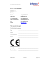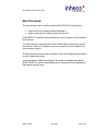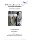
1
Air Conditioner Heater ACAC-180W Ex Proof Explosion Proof Rating ATEX Zone 2 T5 Protected against dust and water to IP55 Part number 8700001 User Manual Part no. 900273-001 May 2015 Air Conditioner ACAC-180W Ex Proof INHECO Industrial Heating and Cooling GmbH reserves the right to modify their products for quality improvement. Please note that such modifications may not be documented in this manual. This manual and the information herein have been assembled with due diligence. INHECO GmbH does not assume liability for any misprints or cases of damage resulting from misprints in this manual. If there are any uncertainties, please feel free to contact [email protected]. → How to contact INHECO, page 4. The brand and product names within this manual are registered trademarks and belong to the respective titleholders. INHECO GmbH Version 001 page 2 of 30 Air Conditioner ACAC-180W Ex Proof Table 1: Version VERSION NO. 1.0 2.0 PUBLISHED DATE August 2002 October 2002 2.1 March 2003 000 February 2012 000 November 2012 001 May 2015 INHECO GmbH CHANGES FROM THE PREVIOUS VERSION Temperature class changed from T4 to T5; Description of fuse for ambient side fan included; Service instructions updated; Heating curves of Air Conditioner Heater included, Directives satisfied changed from 3G EEX nL IIA T5 X to 3G EEX nA IIA T5 X - surface roughness instead of flatness of the gasket area (chapter 6) - missing reference in chapter 6 - German translation and correction of errors - Use for intended purpose added -Transient surge suppression added - Minimum distance at installation - Note on stability of the switch cabinet wall - Torque for installation specified - Overheating safety function, cut-out at +75°C - Each of the fans requires an electrical fuse - Technical data: higher ambient temperature - Technical data: ambient side satisfies IP55 - Circuit diagram: second fuse added - Name plate - EC Declaration of Conformity - TÜV certificate deleted - Changes in contact details Hotline and Fax - EC type examination certificate (Bureau Veritas) - Explanation of symbols: symbols changed - EC Declaration of Conformity: marking number corrected - EC-Type examination certificate Version 001 page 3 of 30 Air Conditioner ACAC-180W Ex Proof How to contact INHECO: INHECO GmbH 82152 Martinsried Germany Tel: Sales E-mail: Sales +49 (0)89 899593-101 [email protected] Tel: Technical Hotline E-mail: Technical Hotline +49 (0)89 899593-201 [email protected] Fax: Website +49 (0)89 899593-149 www.inheco.com This manual belongs to To be filled in by the customer: Type __________________________________________________ Serial # __________________________________________________ Year of manufacture __________________________________________________ Order # __________________________________________________ Inventory No. __________________________________________________ Place of installation __________________________________________________ INHECO GmbH Version 001 page 4 of 30 Air Conditioner ACAC-180W Ex Proof About this manual This manual is part of the Air Conditioner Heater ACAC-180-W Ex Proof and must be retained until the Air Conditioner Heater is disposed of. passed on when the Air Conditioner Heater is sold or lent. Contact INHECO in case there are any uncertainties of how to operate or how to handle the Aid Conditioner. Your opinion about this manual provides us with valuable insights on how we can improve this document. Please do not hesitate to send your comments to us at the address or the phone numbers on page 4. The safety instructions must be read very carefully. They must be understood and observed in order to ensure safe working. Lack of knowledge or insufficient knowledge of the manual will invalidate claims against INHECO GmbH. The operator should therefore ask for confirmation from the manufacturer that instruction has been given. INHECO GmbH Version 001 page 5 of 30 Air Conditioner ACAC-180W Ex Proof Content 1 EXPLANATION OF SYMBOLS .................................................................................. 7 2 SAFETY INSTRUCTIONS ........................................................................................... 8 2.1 2.2 2.3 3 FOR YOUR OWN SAFETY ......................................................................................... 9 3.1 3.2 3.3 4 TECHNICAL MODIFICATIONS .................................................................................... 9 MALFUNCTIONS ..................................................................................................... 9 NAME PLATE AND LABELS ....................................................................................... 9 OTHER HAZARDS.................................................................................................... 10 4.1 4.2 4.3 5 CONVENTIONAL USAGE .......................................................................................... 8 WHO IS PERMITTED TO OPERATE THIS UNIT? ............................................................ 8 DECOMMISSIONING AND DISPOSAL .......................................................................... 8 ELECTRIC SHOCK HAZARD .................................................................................... 10 BURN HAZARD ..................................................................................................... 10 RISK OF INJURY ................................................................................................... 10 INITIAL OPERATION ................................................................................................ 11 5.1 5.2 SCOPE OF SUPPLY ............................................................................................... 11 USE FOR THE INTENDED PURPOSE ........................................................................ 12 6 INSTALLATION ........................................................................................................ 13 7 DISMOUNTING ......................................................................................................... 17 8 INITIAL OPERATION ................................................................................................ 18 9 SAFETY INSTRUCTIONS FOR OPERATION .......................................................... 20 10 SERVICE INSTRUCTIONS ....................................................................................... 22 10.1 10.2 10.3 11 CLEANING ........................................................................................................... 22 FULL SERVICE ..................................................................................................... 22 FUSE .................................................................................................................. 22 TECHNICAL DATA ................................................................................................... 23 11.1 11.2 11.3 TECHNICAL DATA ................................................................................................ 23 DIMENSIONAL DRAWING ....................................................................................... 24 OPERATING CHARACTERISTIC CURVES .................................................................. 25 12 WIRING SCHEMATIC AND CIRCUIT DIAGRAM ..................................................... 27 13 EC DECLARATION OF CONFORMITY .................................................................... 29 14 NAME PLATE ........................................................................................................... 30 INHECO GmbH Version 001 page 6 of 30 Air Conditioner ACAC-180W Ex Proof 1 ! Explanation of symbols DANGER !! A high possible danger, leading to serious bodily harm or even death is being pointed out to you. ! A possible danger, leading to serious bodily harm or even death is being pointed out to you. WARNING ! !!! ! A possible danger leading to less serious bodily harm is being pointed out to you. CAUTION A possible dangerous situation leading to material damage is being pointed out to you. Important! This sign refers to useful information as to installation etc. Note Bullet points refer to enumeration. These arrows are intended to give instructions. These squares refer to procedures which run automatically and results which should be achieved. INHECO GmbH Version 001 page 7 of 30 Air Conditioner ACAC-180W Ex Proof 2 Safety Instructions 2.1 Conventional usage The AIR CONDITIONER HEATER units are state-of-the-art devices and comply with today’s standards. The manufacturer attached much importance to the user’s safety. The following rules apply to the user: Rules of accident prevention General rules for technical safety EU and other national directives Conventional usage include usage as listed in this manual. This unit is to be used only in the specified environment. 2.2 Who is permitted to operate this unit? Only trained skilled personnel are permitted to install and operate this unit. 2.3 Decommissioning and disposal The unit must be disposed of according to the applicable environmental directives. INHECO GmbH Version 001 page 8 of 30 Air Conditioner ACAC-180W Ex Proof 3 ! WARNING ! !!! For your own safety Disconnect the unit from the power supply when installing it. By doing so accidents can be avoided. 3.1 3.2 Technical modifications For reasons of safety, no technical modifications to this unit are allowed. Any modification or change which is not approved by the manufacturer will invalidate the warranty. The original parts are designed especially for the AIR CONDITIONER HEATER. Parts provided by other suppliers have not been tested and are therefore not approved by INHECO GmbH. Using them can lead to impairment of the functionality of the unit. INHECO GmbH accepts no liability for damage which may occur due to the use of parts other than original parts. Malfunctions If any malfunction occurs, report it immediately to the responsible person. Make sure the unit is secured against vandalism and misuse. If any safety-relevant parts are removed, they must be reinstalled and checked before restarting operation. 3.3 Name plate and labels Please check all name plates and labels and ensure they remain legible. Replace any name plates and labels that are no longer legible. INHECO GmbH Version 001 page 9 of 30 Air Conditioner ACAC-180W Ex Proof ! WARNING ! !!! 4 Other hazards 4.1 Electric shock hazard If the unit is not connected properly or if the unit is not disconnected from the power supply when working with the cabinet open or during installation, you may suffer an electric shock. Please observe the following measures in order to avoid muscle convulsions, burns, unconsciousness, cessation of breathing and even death: Do not work on the unit with the cabinet open when it is connected to the power supply. The unit is operated at a voltage of up to 24 V DC and takes a current of up to 15 A DC. 4.2 ! CAUTION ! CAUTION Burn hazard You may burn your skin when touching the heat sinks of the AIR CONDITIONER HEATER. These heat sinks can reach temperatures up to 75°C! The heat sink cools down only slowly after the unit has been switched off. 4.3 Risk of injury You may injure yourself if you touch the impeller by hand when it is running. You may also be injured if you move items you are holding into the sweep of the impeller when it is running. Do not remove the finger guard until the power has been switched off. INHECO GmbH Version 001 page 10 of 30 Air Conditioner ACAC-180W Ex Proof 5 Initial Operation 5.1 Scope of supply Before commissioning, check that the device was delivered complete and undamaged. The following components are included in the scope of supply: Air Conditioner Heater incl. gasket, Handling instruction this manual Air Conditioner Heater Gasket Figure 1: Scope of supply INHECO GmbH Version 001 page 11 of 30 Air Conditioner ACAC-180W Ex Proof 5.2 Use for the intended purpose The Air Conditioner Heater is intended for heating and cooling of switch cabinets which are located in zone 2 potentially explosive atmospheres in accordance with Directive 94/9EC. The switch cabinet may be installed either in a protected environment or in the open air. A precondition for the use of the Air Conditioner Heater in Zone 2 is that the switch cabinet satisfies at least the requirements of Index of Protection IP54 and is also approved for Ex zone 2. When correctly installed the gasket supplied with the Air Conditioner Heater offers IP55 protection. Correct installation is described on the following pages. Figure 1 (sectional view): there is no air flow between the module and the inside and outside of the switch cabinet. The cabinet with IP54 protection is not part of the module and is provided by the operator. The appropriate degree of dirt on the module side is stated in DIN IEC 60664-1. INHECO GmbH Version 001 page 12 of 30 Air Conditioner ACAC-180W Ex Proof 6 Installation The unit may be installed only by appropriately trained personnel! Use only the correct tools for all types and sizes of screws. Important! Make sure that all air inlets and air outlets on both the ambient and cabinet sides are open so that air can circulate without obstruction. Check whether the distance between the inlets and all walls are at least 40 mm at the ambient side and 30 mm at the cabinet side. Check also that the air flow that exits the heat sink does not strike the wall of the cabinet, since otherwise turbulence will occur which may affect the reliability of operation. Use flow channels or air shields to direct the air flow to areas where it is needed. If the flow channels and shield plates for the unit at the installation location does not comply with the required minimum distances, the heating and cooling performance of the unit cannot be guaranteed Each fan must be protected by an electrical fuse in accordance with the standard IEC 60127-2 as to limit the maximum current, see section 12 Terminal diagram or the circuit diagram. When the fuse is fitted within the zone 2, its installation must satisfy section 9 of EN 60079-15. ! DANGER !! ! DANGER !! Ensure that the Air Conditioner Heater is operated only when this fuse is in proper condition. Never operate the Air Conditioner Heater with a fuse whose rating is different to this. Danger! If the unit is operated without a fuse or with a fuse whose rating is different to that specified, the Air Conditioner Heater is no longer ATEX certified! In environments which require ATEX certification, do not use the Air Conditioner Heater without a fuse or with a fuse whose rating is different to that specified! The unit must be provided with a device for suppression of transient surges. The device for suppression of transient surges must reduce surges to a maximum of 140% (33.6 V DC) of the operating voltage. Danger! If the overvoltage is higher than +40%, the Air Conditioner Heater no longer complies with the ATEX rating! INHECO GmbH Version 001 page 13 of 30 Air Conditioner ACAC-180W Ex Proof Installation procedure: Insert the 8 screws size 10 with washers and lock washers from inside to outside through the securing holes in the cabinet wall. Check whether the area for the gasket around the cut-out in the cabinet wall is properly finished and free of dirt, dust and foreign bodies. Recommended surface roughness: Rt = 50 - 160µm. Position the gasket on the outside of the cabinet wall. The ends of the 8 screws size 10 serve to position the gasket. Check the seating and position of the gasket. Both sides of the gasket and opposite surface of the installation frame must be clean, flat, undamaged and free of grease or parting agents. Pick up the Air Conditioner Heater, hold it upright and fit it into the recess in the switch cabinet cabinet wall. Secure it with 8 screws size 10 UNC. The screws should be tightened across diagonals in three stages to ensure the gasket is evenly compressed. During the first stage apply 50 % torque, during the second stage 80 % torque and during the third stage apply full torque. The torque should be 4.2 Nm, to ensure the gasket functions correctly. Please check that the applied torque does not damage the screw thread. Make sure that the cabinet wall is tightly sealed against the gasket and is not deformed. Check the torque 24 hours after installation. INHECO GmbH Version 001 page 14 of 30 Air Conditioner ACAC-180W Ex Proof Switch cabinet wall Enclosure fan Gasket Washer Screw #10 UNC Hole #10-24 UNC depth 0.354in [9mm] Figure 2: Installation of the Air Conditioner Heater, working from outside the switch cabinet ! WARNING ! Check visually that the gasket between the ambient side heat sink base and the cabinet fits properly and is undamaged. Switch off the power to the cabinet. Connect the 7 leads to the power supply (controller) inside the cabinet as specified, see also section 12 Terminal diagram. Connect the 4 leads of the ambient side and the cabinet side sensor with the interface of the Air Conditioner Heater control unit. INHECO GmbH Version 001 page 15 of 30 Air Conditioner ACAC-180W Ex Proof ! DANGER !! Danger! If either or both of the sensors is not connected, the Air Conditioner Heater no longer complies with the ATEX rating! In environments which require ATEX certification use the Air Conditioner Heater only when both temperature sensors are connected! INHECO GmbH Version 001 page 16 of 30 Air Conditioner ACAC-180W Ex Proof 7 ! WARNING ! !!! Dismounting The unit may be installed or reinstalled only by appropriately trained personnel! Use only the correct tools for all screws. Switch off the main switch for the AIR CONDITIONER HEATER. Disconnect the 7 leads from the power supply within the cabinet (see page 18). Disconnect the 4 leads from the 2 temperature sensors. ! DANGER !! Danger! Do not try to remove the temperature sensors from their sensor holes, as they are glued down. Warning! If either or both of the sensors are damaged, the Air Conditioner Heater no longer complies with the ATEX rating! In environments which require ATEX certification use the Air Conditioner Heater only when both temperature sensors are undamaged! Remove the 8 size 10 screws. Be careful to support the unit so it does not fall down, as once the screws are removed there is nothing to restrain it. Take out the unit through the cut-out in the cabinet wall. If necessary take off the gasket from the base of the ambient side heat sink or the cabinet wall. Before reinstalling the unit, check the screws, the screw threads and the gasket for damage. ! DANGER !! Danger! When installing the unit, use only undamaged or original parts! Warning! If screws or / and the gasket are damaged, the Air Conditioner Heater no longer complies with the ATEX rating! In environments which require ATEX certification use the Air Conditioner Heater only when the screws and gasket are undamaged! Replace damaged parts according to the replacement parts list. INHECO GmbH Version 001 page 17 of 30 Air Conditioner ACAC-180W Ex Proof 8 Note Initial Operation For the exact specifications of the Temperature Controller for the Air Conditioner Heater please refer to the corresponding manual. Please check: The temperature controller must ensure that even in the worst case the voltage does not exceed 40% of the specified maximum nominal voltage. The controller is not included in the scope of supply of the Air Conditioner Heater. For this reason the unit is marked with the symbol "X" in accordance with the ATEX standard EN 60075-15 section 13c. Turn on the power for the AIR CONDITIONER HEATER. Check the proper operation of the ambient side fan. When connected correctly the air flows through the fan and exits from both ends of the ambient side heat sink. Check the correct operation of the cabinet side fan. When connected correctly the air flows through the fan and exits from both ends of the ambient side heat sink. To avoid malfunction of the Air Conditioner, the fan have to work in the cooling mode. To avoid malfunction of the Air Conditioner, the cabinet fans have to work in the heating mode. Check the operation of the heating or cooling function: In cooling mode the heat sink inside the cabinet is cold, the heat sink outside the cabinet is hot. In heating mode the heat sink inside the cabinet is hot, the heat sink outside the cabinet is cold. Using a temperature sensing device, attempt carefully to check these temperature differences at the marked points on the bases of the two heat sinks. If the heat sink temperature rises above +75 C (+167 °F), the Air Conditioner Heater must shut down automatically. Check whether the ambient side and the cabinet side temperature sensors measure the same temperature as measured by the temperature sensing device (tolerance +/- 2 °C). Please check: The ambient side fan must run only when the ambient temperature is above +4 °C (+40 °F) and switch off when the ambient temperature is below +4 °C (+40 °F). When starting or restarting at an ambient temperature lower than +4 °C (+40 °F): the cabinet side fan must be pre-warmed to above +20 °C (+68 °F). Ensure this INHECO GmbH Version 001 page 18 of 30 Air Conditioner ACAC-180W Ex Proof temperature with a short run in heating mode before switching on or connecting to the power supply. Otherwise damage cannot be excluded. ! DANGER !! Danger! Do not run the unit without testing the proper operation of the heating and cooling mode and the proper operation of the ambient and cabinet side temperature sensors. Otherwise overheating and damage to the unit and surrounding equipment can occur! If the heating and cooling mode and the ambient and cabinet side temperature sensors are not working properly, the Air Conditioner Heater no longer complies with the ATEX rating! In environments which require ATEX certification use the Air Conditioner Heater only when the heating and cooling mode is operating correctly and the ambient and cabinet side temperature sensors are operating correctly! INHECO GmbH Version 001 page 19 of 30 Air Conditioner ACAC-180W Ex Proof 9 ! CAUTION ! Safety instructions for operation To avoid injuries and damage, an unimpeded air supply must be ensured at both heat sinks. To prevent damage to the AIR CONDITIONER HEATER, the specified ambient temperature must not be exceeded (see 11.1). Lift the unit carefully. To prevent damage to the thermoelectric modules, avoid side loads or pressure on the heat sinks. Use the unit only within the specified range of DC voltage and current (see 11.1). The unit operates only on DC and not on AC. DANGER !! Danger! If the unit is connected to a power supply other than the specified DC voltage, the Air Conditioner Heater is no longer ATEX certified! In environments which require ATEX certification, do not use the Air Conditioner Heater connected to a power supply other than the specified DC voltage! ! Warning! To avoid injuries by electric shock, disconnect the unit from the power supply system before any work on the unit. Only trained personnel are permitted to install and deinstall the unit. WARNING ! !!! The Air Conditioner Heater has two temperature sensors installed, one on the ambient side and one on the cabinet side heat sink, to monitor the proper operation of the Air Conditioner Heater and to alert about possible malfunctions. It is strongly recommended that the controlling device for these two sensors is able to detect a possible broken wire for each of these sensors. Possible malfunctions of the Air Conditioner Heater are: Failure of the ambient side fan Failure of the cabinet side fan Failure of the temperature controller Power supply failure Operation at temperatures above the specified ambient temperatures INHECO GmbH Version 001 page 20 of 30 Air Conditioner ACAC-180W Ex Proof All these malfunctions can lead to increased temperatures inside the Air Conditioner Heater, especially at the ambient side. These increased temperatures can damage parts of the Air Conditioner Heater. ! DANGER !! Danger! If the Air Conditioner Heater or parts of the Air Conditioner Heater are operated at temperatures higher than specified, the Air Conditioner Heater no longer complies with the ATEX rating! In environments which require ATEX certification, do not use the Air Conditioner Heater after it has been operated at temperatures higher than specified! INHECO GmbH Version 001 page 21 of 30 Air Conditioner ACAC-180W Ex Proof 10 Service Instructions 10.1 Cleaning Regularly check that the fans and the heat sinks on the ambient and the cabinet side are free from dust and dirt. If necessary blow out the fans and heat sinks with compressed air. Take care that the compressed air does not damage the impeller bearing! Also check the leak-tightness of the gasket and check that all screws are tightened to the correct torque. 10.2 ! DANGER !! Full service Provided the AIR CONDITIONER HEATER is operated within the specified ambient conditions, a FULL SERVICE of the unit is recommended after 5 years of operation (43,500 hours). The FULL SERVICE of the AIR CONDITIONER HEATER must be performed by INHECO GmbH or by authorised partners from INHECO GmbH. Danger! If after 5 years of operation the unit has not been given a FULL SERVICE by an authorized person, the Air Conditioner Heater may no longer conform to ATEX certification! In environments which require ATEX certification, do not use the Air Conditioner Heater after 5 years (43,500 hours) of operation unless the unit has been given a FULL SERVICE! Please contact us for further information on authorized partners of INHECO GmbH. 10.3 Fuse Each fan must be protected by an electrical fuse in accordance with the standard IEC 60127-2 as to limit the maximum current, see section 12 Terminal diagram or the circuit diagram. ! DANGER !! Ensure that the Air Conditioner Heater is operated only when this fuse is in proper condition. Never operate the Air Conditioner Heater with a fuse whose rating is different to this. Danger! If the unit is operated without a fuse or with a fuse whose rating is different to that specified, the Air Conditioner Heater is no longer ATEX certified! In environments which require ATEX certification, do not use the Air Conditioner Heater without a fuse or with a fuse whose rating is different to that specified! The fuse is not a part of the Air Conditioner Heater! INHECO GmbH Version 001 page 22 of 30 Air Conditioner ACAC-180W Ex Proof 11 Technical Data 11.1 Technical Data Table 2: Data of the ACAC-180-W Ex proof Max. power at +25 °C (+77 °F) ambient temperature and T = 0 °C (+32 °F) Operating voltage for TEC and fans Maximum operating current TEC Operating current of the cabinet fan (internal space) Operating current of the ambient fan Maximum power consumption Max. ambient temperature Min. ambient temperature Weight Index of Protection cabinet fan (internal space) Index of Protection ambient fan Maximum noise level Equipment category Overall Dimensions INHECO GmbH Version 001 176 W (600 BTU/h) see operating characteristic curves 24 V DC 20 A DC 0.395 A DC ±12.5% 0.600 A DC ±12.5% 480 W at 24 V DC +55 °C (+131 °F) -40 °C (-40 °F) 9.4 kg (20.7 lb) IP20 IP55 65 dBA II 3G Ex nA IIA T5 Gc H 254 mm x W 178 mm x D 244 mm (H 10” x W 7” x D 9.6”) page 23 of 30 Air Conditioner ACAC-180W Ex Proof 11.2 Dimensional drawing Figure 2: Dimensional drawing of the Air Conditioner Heater, all dimensions in mm INHECO GmbH Version 001 page 24 of 30 Air Conditioner ACAC-180W Ex Proof 11.3 Operating characteristic curves Air Conditioner Heater ACAC-180W 10 °C delta T (°C) 0 °C +25 °C ambient -10 °C +60 °C ambient -20 °C -30 °C -40 °C -50 °C 0W 50 W 100 W 150 W 200 W 250 W Capacity (W) Air Conditioner Heater ACAC-600BTU/HR 10 °F delta T (°F) -10 °F +77 °F ambient -30 °F +140 °F ambient -50 °F -70 °F -90 °F 0 BTU/HR 100 BTU/HR 200 BTU/HR 300 BTU/HR 400 BTU/HR 500 BTU/HR 600 BTU/HR 700 BTU/HR 800 BTU/HR Capacity (BTU/HR) Figure 3: Cooling curves of the Air Conditioner Heater in metric and US units INHECO GmbH Version 001 page 25 of 30 Air Conditioner ACAC-180W Ex Proof Figure 4: Heating curves of the Air Conditioner Heater in metric and US units INHECO GmbH Version 001 page 26 of 30 Air Conditioner ACAC-180W Ex Proof 12 Wiring schematic and circuit diagram Table 3: Wiring of the Air Conditioner Heater Description TEC + TEC Fan cabinet side + Fan cabinet side Fan ambient side + Fan ambient side PE GND Sensor ambient side Sensor ambient side Sensor cabinet side Sensor cabinet side TEC: Cable length: End of cables: INHECO GmbH Wire-No. 1 2 3 4 5 6 7 8 9 10 11 AWG 10 (6.0 mm2) 10 (6.0 mm2) 10 (6.0 mm2) 10 (6.0 mm2) 10 (6.0 mm2) 10 (6.0 mm2) 12 (4.0 mm2) 18 (0.75 mm2) 18 (0.75 mm2) 18 (0.75 mm2) 18 (0.75 mm2) Color Black Black Black Black Black Black GN/YE Black Black Black Black Cooling mode: wiring as shown in Table 3 Heating mode: TEC polarity must be switched 20 feet (6.10 m); Sensor cable: three-core 18 inches End splices marked with permanent wire marker tags, heat shrink covered, clear Version 001 page 27 of 30 Air Conditioner ACAC-180W Ex Proof Circuit Diagram Custo mer INHECO Enclosure side Ambient side 1 TEC configuration 2 3 Fuse 630mA slow-blow Fan enclosure side Fan ambient side with IP55 4 5 Fuse 800mA slow-blow 6 7 PE GND 8 9 10 11 INHECO GmbH Sensor ambient side PT100 type B Sensor enclosure side PT100 type B Version 001 page 28 of 30 Air Conditioner ACAC-180W Ex Proof 13 EC Declaration of Conformity on the basis of a voluntary test in accordance with Annex VIII of the Directive 94/9/EC of the council for equipment and protective systems intended for use in areas with potentially explosive atmospheres. Product: Model: Marking: Approval: Manufacturer: ACAC-180W 8700001 II 3G Ex nA IIA T5 Gc EPS 11 ATEX 1 401 X INHECO Industrial Heating and Cooling GmbH 82152 Martinsried Germany The product mentioned above fulfils the basic requirements of the Directive 94/9/EC 2006/95/EC 2004/108/EC ATEX Directive Low Voltage Directive EMC Directive and conforms to the following standards EN 600079-0:2009 EN 600079-15:2010 Potentially explosive atmospheres - part 0: General requirements for equipment Potentially explosive atmospheres - part 15: Equipment protection by ignition "n" The product named is intended for incorporation into other equipment. Operation is permitted only once the end product has satisfied the requirements of the Directives listed above. This statement does not warrant any characteristics regarding product liability. The safety instructions stated in the User Manual must be adhered to. Günter Tenzler Managing Director May 2015 INHECO GmbH Version 001 page 29 of 30 Air Conditioner ACAC-180W Ex Proof 14 Name plate INHECO GmbH, 82152 Martinsried, Germany Manufacturer Module name Item number INHECO Serial number PN SN Date of manufacture Equipment group/category Ambient conditions Max. power consumption ACAC-180W Ex Proof 8700001 XXXX YYYY-MM Ratings maintained Ambient temperatures Power supply II 3G Ex nA IIA T5 Gc -40°C (-40°F) ≤ Ta ≤ +55°C (+131°F) Pi=480W @ 24V DC CE mark --- RoHS kite mark --- CE conformity certificate number INHECO GmbH Certificate no. Version 001 EPS 11 ATEX 1 401 X page 30 of 30