1
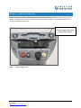
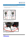
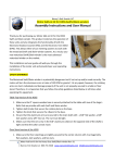
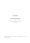
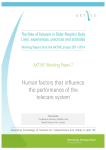
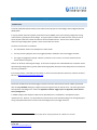
Allegro Technical Service Bulletin 2014_06_20 June 2014 Introduction AI recently identified a potential safety issue related to the improper use of the Allegro with the Digital Voltmeter (DVM) option. It may be possible, when three specific circumstances occur at once, to short the incoming voltage that is being measured to the ground plane of the Allegro. This ground plane includes the metal shroud on the 9-pin port on top of the pod as well as the metal connector to the external GPS antenna. The risk occurs when a person measures a high voltage (42V or greater1) at the moment this short occurs. The three circumstances are as follows: 1. The stick/chainer switch in the DVM pod is in chainer mode. 2. A survey accessory (hip pack, data cane, triggered probe) is attached to the remote trigger connector. 3. The trigger is engaged (for example, a button is pressed on a cane or there is a contact closure from the chainer wheel in a hip pack). There is no risk when measuring low voltage. In the event of improper use as described above, an operator can be exposed to high voltage (42V or greater) while contacting exposed metal parts of the Allegro that are connected to the unit’s ground plane. If you have questions, need additional information, or have a comment about this document, contact AI Technical Services at [email protected]. Solution Disconnect all cables from the remote trigger connector and cover that connector with the rubber cap included with the Allegro BEFORE making any voltage measurement greater than 42 Volts AC or DC. This action guarantees safe operation of all Allegro units. Please see Appendix 1: Remote Trigger Input and Appendix 2: Close Interval Survey Configuration. In addition, Allegro units shipped or repaired since April 2014 have a modification in the expansion pod to minimize this risk. However, it is still possible to create the short circuit outside the Allegro unit through improper wiring of peripheral devices that connect measured voltage to the 3-pin trigger connector. 1 The International Electrotechnical Commission (IEC) defines anything below 42V AC or 60V DC as a safe level. Allegro Technical Service Bulletin 2014_06_20 June 25, 2014 [email protected] 1 Notes There have been no reported occurrences of this issue in nearly 13 years of operation. We discovered the risk during a circuit design review to evaluate future product development. We have chosen to be proactive and to notify all users. There is no risk during normal operation as described in the user manual and demonstrated during training: For periodic survey measurements, do not use a triggered probe to measure high voltages. For close interval surveys, always use a separate test lead wire between the hip pack and the positive banana jack on the DVM. NOTE: Some legacy hip packs may enable voltage sensing of the trailing wire through the 3-pin connector. This is not a recommended configuration and will no longer work on modified Allegro units. If you have any additional questions, please contact your Allegro salesperson: Steve Hamblin (303) 885-6818; Barb Harwell (303) 515-4439; or Jonathan Musgrave (512) 249-3429. You may also contact our customer support team at (512) 249-3400. Allegro Technical Service Bulletin 2014_06_20 June 25, 2014 [email protected] 2 APPENDIX 1: REMOTE TRIGGER INPUT BEFORE MAKING ANY VOLTAGE MEASUREMENT GREATER THAN 42 VOLTS AC OR DC: Disconnect any cable from the Remote Trigger input (see Figure 1, below) and replace the rubber cap before making voltage measurements using the red and black banana jacks. Remote trigger input with rubber cap installed. Figure 1. Remote Trigger Input Allegro Technical Service Bulletin 2014_06_20 June 25, 2014 [email protected] 3 APPENDIX 2: CLOSE INTERVAL SURVEY CONFIGURATION Using the Allegro for Close Interval Survey (from the Allegro MX User Guide): When using a hip pack to measure voltages, always connect the hip pack test lead to the red banana jack on the Allegro (Figure 2 and Figure 3). Figure 2. Allegro and Hip Pack Connections – View 1 Figure 3. Allegro and Hip Pack Connections – View 2 Allegro Technical Service Bulletin 2014_06_20 June 25, 2014 [email protected] 4