1
International Journal of Computer Applications (0975 – 8887)
Volume 56– No.18, October 2012
Vision System via USB for Object Recognition and
Manipulation with Scorbot-ER 4U
Alejandra Cruz Bernal
Gilberto Moreno Aguilar
Department Robotic Engineering
Polytechnic University of Guanajuato
Cortazar, Guanajuato, México
Department Mechatronic Engineering
Technology University of Huejotzingo
Huejotzingo, Puebla, México
ABSTRACT
Through this paper presents the development of a controller
for a Scorbot Er-4u didactic manipulator, using a vision
system communicating via the USB port. Considerate that
nowadays, robotics is an essential element for the
automatization in manufacturing process. As particular
advantage over other systems, failure to use interfaces that
involves development of additional hardware controller itself.
Also, should the question arise, of improve a new form of
generate trajectories through Minimum Euclidian Distance
(MED). This results yielded handling objects, plus the ability
to perceive the environment through the artificial vision
system using image processing and MED, in order to generate
information elements surrounding the manipulator, allowing
the robot classify objects in your workspace, establishing a
fine line between reachable and skilful.
General Terms
Object Recognition, Manipulator Robot, Vision System.
Keywords
Vision System, USB Port, Image Processing, Minimum
Euclidian Distance (MED).
volume of space within which every point can be reached by
the effector in all possible orientations.
1.2 Scorbot-Er 4u Educational
Manipulator
The Scorbot-Er 4u robot is a versatile and reliable system for
educational use, it have a mechanical structure, vertically
articulated, open frame with five rotational axes and gripper
[2]. Therefore, the mechanical transmission system of this
robot consists on gear, timing belts, and lead screws principal.
1.2.1 MITS (Matlab Toolbox for Inteliteck
Scorbot)
Users can only control the arm using Scorbase - Intelitek's
proprietary, stand alone programming environment (Scorbase
is the operation software and robotic programming).The
Scorbot-Er 4u version uses a USB interface and conceals the
API. With [3] Toolbox, provides a set of libraries (DLLs and
M-files) that let you control the robot directly using Matlab
(see figure 1).
1. INTRODUCTION
USB
In recent decades robot manipulators have been used
primarily for repetitive operations and hazardous
environments. In industrial systems, the computer vision
system is part of an automated control system, or an
inspection system (basically on-off). Hence, trajectories
programming industrial robots (industrial manipulators),
focuses on the performance of specific tasks, but when you
take them with a stage in which the manipulator involves
decision making, this gives a certain degree of autonomy to
the manipulator. This contributes to better programming the
trajectory of the manipulator, which in turn reduces the time
in production lines.
When establishing communication to perform control actions
between the manipulator and the vision system that acts as a
controller, via USB, allows, all takes place under the same
communication protocol, enabling real-time action thus
avoiding a double programming to perform the same action.
1.1 Workspace Geometry
The workspace of a manipulator is defined as the volume of
space the end effector can reach [1]. Therefore, are specified
two types of workspace: reachable workspace and dextrous
workspace. In the first, is considerate to the volume of space
within which every point can be reach by the effector in at
least one orientation. While, in the dextrous workspace is the
MTIS
LINK’S DLL
TOOLBOX
INTELITEK DLL
Fig 1: Control Structure MITS via USB.
1.3 System Vision
Machine vision techniques have matured rapidly in the past
twenty years, changing both hardware and software [4]. But
how currently defined vision and artificial elements include a
vision system? Defined as part of artificial intelligence and is
the set of techniques and models to process, analyze and
explain that spatial (3D) obtained from a digital image (2D).
The elements of a vision system are camera and optics,
lighting, positioning sensor, video capture card, computer
vision software and inputs and outputs of the network
configuration.
In all vision system should address the following parameters:
Field of vision: It is the area of the object that will be
10
International Journal of Computer Applications (0975 – 8887)
Volume 56– No.18, October 2012
catch for the sensor.
Resolution: It is a measure of the capacitance of the
vision system to reproduce the details of one object.
Distance of work: It is the measured distance from the
lens of the camera until the object.
Depth of field: It’s the area opposite and behind the
object that is studying and remains focused for the lens,
also it’s named the focusing tolerance.
Size of the sensor.
Distortion: It’s the change unwanted in the form of a
present object in the field of vision.
These parameters are indispensable for the development of
vision software.
2. REVIEW
Several projects that involves the control of the Scorbot by
means of the use of Matlab Software or incorporating a
system of vision, we found, a project called cut laser [5] that
his authors describe, the robot will has a conduct like a
printing machine in whose final effector will has a laser and it
will draw or in his defect will cut metal. The game tic tac toc,
whose end is that the robot by means of a system of vision can
select someone of the recorded poses to follow the game [6],
The selection of nuts, screw and keys is other project [7] that
uses system of vision for give instructions to the robot of as
classifies they, is to say, incorporate an algorithm of take of
decisions, the system of dynamic guide for Scorbot-Er IX
robot arm by means of artificial vision [8], is a project that
involves the inverse kinematics for obtain the desired
displacement.
These and other projects have some in common, the
communication that it settles between computer and controller
is through the serial port, due to the model of the Scorbot,
moreover, most movements of the robot are pre-engraved,
with exception of the projected system of dynamic guide, in
our case, the model with the works is the Scorbot-Er 4u, it has
the series interface, but according to the manual of the
manufacturer it has been limited this port for security, so the
unique middle of communication a hundred by the hundreds
functional between the computer and the controller is by
means of USB port.
Recent projects used the USB communication of the Scorbot
but, controlled using Bat files, they contain information of
routes of access to the programs or positions previously
burned of the Scorbase, which cause limitations if has not this
software.
We have a few information of the use and employ of the
MTIS, being planned with system vision; however your use
facilitates the communication of the computer to the controller
by means of the employment of the Matlab Software.
In [9] the kinematics problem is defined as the transformation
from the Cartesian space to the joint space and vice-versa.
The solution is through model of representation DenavitHarbenterg. The workspace density function is described with
both planar revolute and variable-geometry-truss manipulators
[10]. A focus reaching subtask, with which involves
computing trajectory for arm manipulator, integrated
approach to kinematic inverse and path planning [11].
3. METODOLOGY
The vision system uses a web FUJ-cam 100, whose
resolution of 352x288, a PC running XP SP3, the MITS
software and Matlab ® 2010.
Before entering the software development environment,
should be set the following parameter:
Working distance = 43.3 in.
Then the camera is calibrated [12] to determine actual
measurements of distances and objects to be displayed, this is
done by placing a grid monochromatic, whose pictures are
5cm (as can be varied and is only used as a reference to
determine relationship between pixel and cm), and by
imaqhwinfo function and a few lines of code, is obtained by
connecting the camera Matlab (Figure 2).
% Update handles structure
start(handles.vidobj);
guidata(hObject, handles);
vidRes = get(handles.vidobj,
'VideoResolution');
nBands = get(handles.vidobj,
'NumberOfBands');
hImage = image(zeros(vidRes(2),
vidRes(1), nBands), 'Parent',...
handles.axes7);
preview(handles.vidobj,hImage);
catch
msgbox('Camera Out')
hImage = image(imread('sin.jpg'),
'Parent',handles.axes7);
end
end
axes(handles.axes1)
background = imread('');
axis off;
imshow(background);
Fig 2: Code for Webcam-Matlab Connection
Once captured the image processing is performed in the same,
to have a binary image, to this, you can count the number of
pixels for each frame, and using the linear relationship of
magnitudes or "rule of three" have the inches each pixel,
equation (1).
Pixcm = (mR*1)(pxC) -1
(1)
Where:
Pixcm = Actual centimeters by Pixel
mR= Measure actual box cm (length)
pxC = Number of pixels counted
Having established the working distance and equivalence of
centimeters per pixel, set the field of view (Figure 3) cut out
the captured image, and thus work on it to determine the
coordinates of the center of the objects present (Figure 4) .
11
International Journal of Computer Applications (0975 – 8887)
Volume 56– No.18, October 2012
1
ScorJtMove(BSEPR)
% Function CutoutImage
2
ScorInit
3
ScorHome
function cut=
cut(image)
[y,x]=size(image);
cut=imagen(45:y,20:x)
4
ScorSetSpeed
5
ScorSetGripper(cm)
6
ScorGetJt
(a)
The function "ScorJtMove" requires five input angle values,
the angle base, shoulder, elbow, tilt and rotation of the grip, so
you can call the dll USB driver.
(b)
3.1.2 Optimal Inverse Kinematic.
The workspace is project of R3 R2 and subsequently
characterizing these projections. Therefore, used the
geometrical method, where have been a translation before a
rotation, first at origin and posteriori point q. This point is
necessary belongs to space R2.
(c)
The procedure is based on finding a sufficient number of
geometric relationships which will involve the end of the
finish element (or effector) coordinates, their coordinate’s
joint and physical dimensions of the elements (see Figure 4
and 5).
(d)
Fig 3: a) Image Original b) Code Cut Out-Image c) Binary
image original d) Reachable workspace.
x
Origin
(xc,yc)
h3
h1
h2
Obj 1
(x1,y1)
Obj 3
(x3,y3)
Obj 2
(x2,y2)
(XC, yC, ZC)
y
Fig 4: Representing the coordinates in R2 of the object and
its distance from the origin.
deuc=|| p – qi||2=[Σi=1n(p – q(x,y))2 ]1/2
(2)
Where:
hi (p, Q) = minq{deuc (p, qi), qi є Q }
(3)
else
hi (p, Q) = 0. (Out-Range).
(4)
For the distances from the origin (Scorbot) to the objects we
will use the MED formula (3 and 4) in R2, using the
coordinates of the centers of each objects (Figure 4).
3.1 Control of Scorbot-Er 4u with MTIS
3.1.1 Functions MITS
Experimenting with Toolbox functions, we found a feature
that allows the positioning of the base degrees, shoulder,
elbow tilt and swivel claw through of:
Fig 5: Representing the coordinates in R2 of the effector.
Therefore the function values are obtained under the MTIS
this relationship, and with the implementation of the
trigonometry’s laws. Moreover this ratio must be limited
according to the measures of the robot, the maximum radius
reached by the Scorbot-Er 4u is 24 in and therefore the
distance h1 or d1 must be less than the maximum radius in R2
contained in dextrous workspace (m in Figure 6).
Elbow, Shoulder and object distance (h1 or d1, see figure 4
and 5) form a triangle, the internal angles can be obtained
using the law of sine and cosines, obtain the representation of
displacement of effector (see Figure 6).
12
International Journal of Computer Applications (0975 – 8887)
Volume 56– No.18, October 2012
if valor==1
Grad([-10 120 -110 -60 0]);
Grad([-65 1 -50 -20 0]);
bolean=gripper(-1);
end
if valor==2
Grad([-10 120 -110 -60 0]);
Grad([40 120 -110 -60 0]);
Grad([40 -1 -50 -20 0]);
bolean=gripper(-1);
end
if valor==3
Grad([-10 120 -110 -60 0]);
Grad([-70 10 -100 20 0]);
bolean=gripper(-1);
end
Camera
else
Grad([40 120 -110 -60 0]);
end
end
Fig 7: Function that calculates the displacement angles of
the robot.
Dextrous
2
Workspace R
Reachable
3
Workspace R
Fig 6: Displacement Representation Effector.
. % Displaccementfor yu=1:Ne3
if mindist>=44.1 && mindist<=58
bolean=gripper(-1);
[an02 an03
pinz01]=parallel(minidistancia);
bolean=robot_l(angle,an02,an03,pinz01
);% Primer movimiento
[an2 an3 pinz]=objeto(mindist);
bolean=robot_l(angle,an2,an3,pinz);%S
egundo moviento bajar
bolean=gripper(0);
cm=mide_garra;
if cm>=1
Grad([10 64 -20 -72 0]);%
Posicion Camara
l_camara;
preview(veo)
pause(5)
color24= getsnapshot(veo);
%closepreview ;
%imshow(color24);
valor =pieza1(color24);
%Function of determinate piece...
Based on these principles will create a function to calculate
the internal angles are generated by changing the distance of
the object (see Figure 7), so that each time the object is a new
distance function returns the new angles.
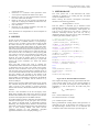
4. RESULTS
Respecting the parameters (table 1), working distance and
field of view, they test for the algorithm created, with the
following results:
The rotation of the base has a margin of error + -4 degrees,
which is offset in the algorithm.
If the object it´s inside range of robot, with a margin of error
of ± 0.25in.
The surface should be matte, because the robot is in constant
illumination variation, which in a reflective surface may cause
the algorithm to detect objects ghosts.
To take the first object makes the robot pose with the distance
the two, and thereafter tends to decrease, which causes an arc
of the initial portion to the end, see figure 6.
If the object is less than 7.87 in, the robot was located just
above it, without pick, with gripper perpendicular to the
surface, because the algorithm is not yet described the pose
that must acquire if it happens.
Placing multiple objects in the workspace, only the object that
is closest to the origin the robot will be the object that will
take the Scorbot.
On the use of MTIS not present problems of communication,
worked perfectly on XP, for other versions of Windows still
in compatibility testing and communication (see figure 8).
13
International Journal of Computer Applications (0975 – 8887)
Volume 56– No.18, October 2012
Table 1.Sumary Parameters.
Date
1-100
1.54 s/ Move
*-100 < 0 > 100
15-57 cm
Process Number Pieces
Response Time
Angle Change
Limit Range
* Not applied the negative value.
Response Time (Execution
Matlab)
4.7
4.6
4.5
4.4
1
2
3
4
5
6
7
8
9 10 11 12 13 14 15 16 17
Tiempo de respuesta
Response
Response Time (MTIS vs RS232)
1.5
1
0.5
0
1
2
3
4
5
6
7
8
MTIS
9 10 11 12 13 14 15 16 17
RS232
Fig 8: The Average Response Time is 1.01.
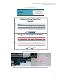
Fig 9: Scorbot-Er-4u in your Reachable Workspace and Detection Objects to Recognition.
14
International Journal of Computer Applications (0975 – 8887)
Volume 56– No.18, October 2012
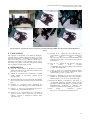
Fig 10: Sequence of Scorbot-Er 4u in your trajectory calculated through of MED, also the selection and classification of
objects.
5. CONCLUSION
The longitude of manipulator in the Dextrous Workspace,
calculated through of MED, allowed smoothing curve in the
trajectory in the effector. Accordingly, to considerate a new
origin in the center of point (or coordinate of object take), is
generated a new trajectory with a efficient response time in
the execution of program, in real-time working with a parallel
process, thank to communication via USB.
6. REFERENCES
[1] Tsai, L.W., “Robot analysis: the mechanics of serial and
parallel manipulators” Wiley Interscience, John Wiley &
Sons, Inc. pp. 21–109, 1999.
[2] Intelitek ®, “Scorbot-Er 4u, User Manual”, Copyright
©2001 Intelitek ® Inc.Catalog #100343 Rev.B.
September 2001.
[3] The MATLAB Toolbox for the Intelitek Scorbot (MTIS),
http://www.usna.edu/Users/weapsys/esposito/scorbot.Ma
tlab/
[7] Sobrado, M. E., “Sistema de visión artificial para el
reconocimiento y manipulación de objetos utilizando un
brazo
robot”
.Tesis
PUCP.
http://tesis.pucp.edu.pe/repositorio/bitstream/handle/1234
56789/68/sobrado_eddie_vision_artificial_brazo_robot.p
df?sequence=2.
[8] Soto, M. C.E, “sistema de guía dinámico para brazo
robot
Scorbot
Er-IX
mediante
visionartificial”,http://cybertesis.ubiobio.cl/tesis/2006/sot
o_c/html/index-frames.html.
[9] Verma, A., Vivek, A.D., “End-effector Position Analysis
of SCORBOT-ER V plus Robot”, International Journal
of Smart Home, Vol.5,No.1, January 2011.
[10] Suthakon, J., Chirikjan G.S., “A new inverse kinematics
algorithm for binarymanipulator with a many actuators”,
Advance Robotics, Vol. 15, No. 2. Pp.225-244 (2001).
[4] Sezeleski. R., “Computer Vision, Algorithms and
Applications”, ©2010 Springer, http://szeliski.org/Book/
[11] Bertram, D., Kuffner, J., Dillmann. R., and Asfour, T.,
“A integrated approach to kinematic inverse and path
planning for redundant manipulators”, Proceedings of the
2006International Conference in Robotics and
Automation, Orlando, Florida, (2006), pp. 1874-1878.
[5] Galnares, J., http://www.prototipando.es/proyectos/73cortadora-laser-scorbot?showall=&start=2.
[12] The
Camera
Calibration
Toolbox,
http://www.vision.caltech.edu/ bouguetj/calib doc/
[6] Almanza, O. D., “Implementación de la estrategia de
juego Tic-Tac-Toe para la interacción con un brazo
robótico”, Avances en Inteligencia Artificial, ISSN:
1870-4069, IPN.
15